page i | preface - energy
TRANSCRIPT


Page i | Preface
U.S. DRIVE
Highlights of Technical Accomplishments Overview Through precompetitive collaboration and technical exchange, U.S. DRIVE accelerates the development of energy-efficient advanced automotive and energy infrastructure technologies.
U.S. DRIVE (Driving Research for Vehicle efficiency and Energy sustainability) is a voluntary government-
industry partnership focused on precompetitive, advanced automotive and related infrastructure technology
research and development. Partners are the United States Department of Energy (DOE) and leaders in the
automotive industry (United States Council for Automotive Research LLC, the collaborative technology
company of FCA US LLC, Ford Motor Company, and General Motors); energy industry (BP, Chevron, Phillips
66, ExxonMobil, and Shell); and electric utility industry (American Electric Power, DTE Energy, Duke Energy,
Southern California Edison, and the Electric Power Research Institute).
The Partnership benefits from a history of successful collaboration across multiple technical areas, each
focused on a key area of the U.S. DRIVE portfolio (see below). These teams convene the best and brightest
scientists and engineers from across the Partnership to discuss key technical challenges, identify possible
solutions, and evaluate progress toward goals and targets published in technology roadmaps. By providing a
framework for frequent and regular interaction among technical experts in common areas of expertise, U.S.
DRIVE accelerates technical progress, helps to avoid duplication of efforts, ensures that publicly-funded
research delivers high-value results, and overcomes high-risk barriers to technology commercialization.
U.S. DRIVE teams selected the highlights in this document from many hundreds of DOE-funded projects
conducted by some of the nation’s top research organizations. Each one-page summary represents what
Partnership experts collectively consider to be significant progress in the development of advanced automotive
and infrastructure technologies. The report features technical highlights in two general categories:
Vehicles
• Advanced Combustion and Emission Control • Electrical and Electronics • Electrochemical Energy Storage • Fuel Cells • Materials
Infrastructure and Integration
• Grid Integration • Hydrogen Codes and Standards
• Hydrogen Delivery and Storage • Hydrogen Production • Net-Zero Carbon Fuels • Vehicle and Mobility Systems Analysis
More information about U.S. DRIVE, including prior-year accomplishments reports and technology
roadmaps, is available on the DOE (https://www.energy.gov/eere/vehicles/us-drive) and USCAR
(www.uscar.org) web sites.

Page ii | Table of Contents
Contents
VEHICLES .......................................................................................................................................... 1
Advanced Combustion and Emission Control ....................................................................................... 1
Direct Numerical Simulation of Flow and Heat Transfer in Internal Combustion Engines ...............................2 Machine Learning Tool and Model Link Injector Wear with Reduced Performance ........................................3 Simulations Provide New Insights into Pre-Spark Heat Release in Boosted Spark Ignition Engines ..............4 Gasoline Surrogate Formulation Developed for PACE Experiments and Engine Simulations ..............................5 Co-Optima Develops Methodology to Quantitatively Value Fuel Properties for Efficiency Potential ...............6 A Power Density High Efficiency Gasoline Lean Combustion Engine .............................................................7 Study Affirms Fuels with High Octane Sensitivity Outperform those with Low Sensitivity at High Loads and Speeds ..............................................................................................................................................................8 Highly Efficient Palladium PNA for NOx Control Enabling SULEV 30 Emission Compliance ..........................9
Electrical and Electronics .................................................................................................................... 10
High-Speed Hybrid Reluctance Motor Utilizing Anisotropic Materials ........................................................... 11 Experimentally Confirmed High Thermal Performance of the Novel Dielectric Liquid Cooling Concept ...... 12 Graphite Embedded High-Performance Insulated Metal Substrate for Wide Bandgap-Based Power Modules ....................................................................................................................................................................... 13 Co-Optimization of Boost Converter Reliability and Volumetric Power Density ............................................ 14
Electrochemical Energy Storage ......................................................................................................... 15
A Lithium-ion Battery Electrolyte Recycling Process ..................................................................................... 16 Highly Uniform Dopant Distributions Improve Life in High-Energy Nickel-Rich Cathodes ............................ 17 Pushing the Limits of Rechargeable Lithium Metal Battery Cycle Life and Energy Density ......................... 18 Towards Higher-Energy Density via State-of-Charge Gradient Determination in Thick Electrodes ............. 19 Lithium-Ion Cell Brings Extreme Fast Charging Closer to Reality for Electric Vehicles ................................ 20 Protocol for Early Assessment of Calendar Life and Faster Technology Development in Silicon-Based Anodes ........................................................................................................................................................... 21 Electrolyte Development for Extreme Fast Charging (XFC) of Lithium-ion Batteries .................................... 22 Sustainable Direct Recovery of Battery Materials from Manufacturing Scraps ............................................. 23 Development of Silicon-Based High-Capacity Anodes for Next-Generation Lithium-Ion Batteries .............. 24 Synthesis of High-Performance Nickel-Rich Cathode Materials for High-Energy Batteries ......................... 25 A New Electrolyte Solvent Molecule Enables Lithium Metal Batteries .......................................................... 26 Improved Extreme Fast Charge Tolerance in Graphite Anodes via Metal Film Surface Coating ................. 27 A New Pathway to Higher Energy Density: Cobalt-Free Cathodes Enabled by 3D Targeted Doping .......... 28 Laser-Patterned Electrodes for Enhanced Fast Charge Capability .............................................................. 29
Fuel Cells ............................................................................................................................................. 30
New Catalyst-Support Materials to Improve Durability .................................................................................. 31 Operating Conditions to Enhance Membrane Electrode Assembly Durability Identified .............................. 32 Ordered Intermetallic Nanoparticle Catalysts Demonstrate High Activity and Improved Durability .............. 33 Fuel Cell Modeling and Cost Analysis Highlight Research Opportunities for Heavy-Duty Vehicles ............. 34
Materials ............................................................................................................................................. 35
Corrosion Protection of Dissimilar Material and Joining for Next-Generation Lightweight Vehicles ............. 36 Low-Temperature Carbonization/Close Proximity Electromagnetic Carbonization ....................................... 37 Self-Sensing Fiber Reinforced Composites ................................................................................................... 38 Ultrasonic Spot Welding of Magnesium to High-Strength Steel Sheets ........................................................ 39 Low-Cost Aluminum and Magnesium Extrusions .......................................................................................... 40 Low-Cost Corrosion Protection for Magnesium ............................................................................................. 41

Page iii | Table of Contents
Room-Temperature Stamping of High-Strength Aluminum Alloys ................................................................ 42 Predictive Tools Development for Low-Cost Carbon Fiber for Lightweight Vehicles .................................... 43
INFRASTRUCTURE AND INTEGRATION ............................................................................................. 44
Grid Integration ................................................................................................................................... 44
Grid Impacts of Electric Vehicle Charging at Scale are Mitigated with Smart Charge Management Solutions ....................................................................................................................................................................... 45
Hydrogen Codes and Standards .......................................................................................................... 46
Hydrogen Wide Area Monitor (HyWAM) ........................................................................................................ 47
Hydrogen Delivery and Storage .......................................................................................................... 48
H2FillS: “Hydrogen Filling Simulation” Model to Enable Innovation in Fueling Processes ........................... 49 50% Carbon Fiber Price Reduction Enabling High Pressure Hydrogen Storage Tanks ............................... 50
Hydrogen Production .......................................................................................................................... 51
Hydrogen from Low- and High-Temperature Electrolysis with Route to $2/kg ............................................. 52 Advancements in Photoelectrochemical Hydrogen Production Enabled by HydroGEN Consortium ........... 53
Net-Zero Carbon Fuels ........................................................................................................................ 54
Assessment of Multiple Pathways for Producing Carbon-Neutral Fuels ....................................................... 55
Vehicle and Mobility Systems Analysis ............................................................................................... 56
VMSATT Future Mobility Scenario Development .......................................................................................... 57
VEHICLES
Advanced Combustion and Emission Control

Page 2 | Advanced Combustion and Emission Control Technical Team
2020 U.S. DRIVE Highlight
Direct Numerical Simulation of Flow and Heat Transfer in Internal Combustion Engines The data generated from these simulations can lead to significantly improved understanding of in-cylinder processes and accurate models for engineering simulations.
Argonne National Laboratory
Comprehensive understanding of intake airflows
and fuel sprays over a wide operating range through
advanced high-fidelity modeling tools has been
identified as a bottleneck to increased adoption of
advanced dilute combustion gasoline engines.
Engine manufacturers currently use commercial
codes that have inherent limitations in predictive
capability and to massive parallelization. With the
emergence of highly scalable, high-order simulation
tools developed using investments from the U.S.
Department of Energy’s exascale computing project
and the availability of leadership class
supercomputers, high-fidelity numerical
simulations have emerged as a viable asset in
improving our understanding of the
multiscale/multi-physics in-cylinder processes and
the impact of design changes on internal combustion
engine (ICE) performance.
Researchers from the Energy Systems (ES) and
Computational Sciences (CPS) divisions at Argonne
National Laboratory recently performed the first
ever Direct Numerical Simulations (DNS) of the
compression and expansion strokes of the GM TCC-
III engine at motored operating conditions. These
simulations, performed with the open-source
Nek5000 code using more than 400 million
gridpoints on more than 50,000 processors of
Argonne’s Theta supercomputer, have delivered
unprecedented insights into the turbulent flow-field
and near-wall heat transfer characteristics in an ICE.
The DNS calculation was initialized using the
velocity and temperature fields from a precursor
multi-cycle wall-resolved large eddy simulation
calculation. Accuracy of several traditional wall
function models to predict the near-wall heat flux
was analyzed across a range of crank angles and it
was shown that all the models underpredicted the
heat flux by as much as 50% (Fig. 1). The DNS
dataset is currently being used to develop improved
wall heat transfer models. Simulations are also being
planned on more modern engine platforms such as
Sandia’s direct injection spark ignition and
upcoming Partnership to Advance Combustion
Engines consortium engines and will complement
engine experiments.
Figure 1. Left: Snapshot of turbulent eddies during the compression stroke from the DNS calculation. Right: Comparison of the near-wall temperature field predicted by DNS compared to the predictions by different commonly used wall function models.
Page 3 | Advanced Combustion and Emission Control Technical Team
2020 U.S. DRIVE Highlight
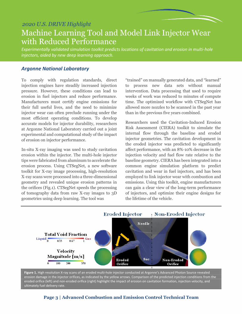
Machine Learning Tool and Model Link Injector Wear with Reduced Performance Experimentally validated simulation toolkit predicts locations of cavitation and erosion in multi-hole injectors, aided by new deep learning approach.
Argonne National Laboratory
To comply with regulation standards, direct
injection engines have steadily increased injection
pressure. However, these conditions can lead to
erosion in fuel injectors and reduce performance.
Manufacturers must certify engine emissions for
their full useful lives, and the need to minimize
injector wear can often preclude running under the
most efficient operating conditions. To develop
accurate models for injector durability, researchers
at Argonne National Laboratory carried out a joint
experimental and computational study of the impact
of erosion on injector performance.
In-situ X-ray imaging was used to study cavitation
erosion within the injector. The multi-hole injector
tips were fabricated from aluminum to accelerate the
erosion process. Using CTSegNet, a new software
toolkit for X-ray image processing, high-resolution
X-ray scans were processed into a three-dimensional
geometry and revealed unique erosion patterns in
the orifices (Fig.1). CTSegNet speeds the processing
of tomography data from raw X-ray images to 3D
geometries using deep learning. The tool was
“trained” on manually generated data, and “learned”
to process new data sets without manual
intervention. Data processing that used to require
weeks of work was reduced to minutes of compute
time. The optimized workflow with CTSegNet has
allowed more nozzles to be scanned in the past year
than in the previous five years combined.
Researchers used the Cavitation-Induced Erosion
Risk Assessment (CIERA) toolkit to simulate the
internal flow through the baseline and eroded
injector geometries. The cavitation development in
the eroded injector was predicted to significantly
affect performance, with an 8%-10% decrease in the
injection velocity and fuel flow rate relative to the
baseline geometry. CIERA has been integrated into a
common engine simulation platform to predict
cavitation and wear in fuel injectors, and has been
employed to link injector wear with combustion and
emissions. Using this toolkit, engine manufacturers
can gain a clear view of the long-term performance
of injectors, and optimize their engine designs for
the lifetime of the vehicle.
Figure 1. High resolution X-ray scans of an eroded multi-hole injector conducted at Argonne’s Advanced Photon Source revealed erosion damage in the injector orifices, as indicated by the yellow arrows. Comparison of the predicted injection conditions from the eroded orifice (left) and non-eroded orifice (right) highlight the impact of erosion on cavitation formation, injection velocity, and ultimately fuel delivery rate.

Page 4 | Advanced Combustion and Emission Control Technical Team
2020 U.S. DRIVE Highlight
Simulations Provide New Insights into Pre-Spark Heat Release in Boosted Spark Ignition Engines New simulation best practices capture the physics of low-temperature pre-spark heat release for internal combustion engines, paving the way to better engine knock control.
Argonne National Laboratory
Accurate capture of low-temperature heat release
(LTHR) is critical for predicting auto-ignition
processes in internal combustion engines (ICEs).
While LTHR is typically obscured by the
deflagration, extremely late ignition phasing can
lead to LTHR prior to the spark, i.e., pre-spark heat
release (PSHR). Argonne researchers developed new
computational fluid dynamics best practices to
model PSHR in a boosted direct-injection spark
ignition (SI) internal combustion engine. A hybrid
approach was proposed, based on the G-equation
model for representing the turbulent flame front,
and the well-stirred reactor model for tracking the
chemistry in the unburnt region. Multicycle
simulations were performed with Co-Optima
Alkylate and E30 fuels. Different than common SI
modeling practices, the well-stirred reactor model
must be kept active throughout the entire
simulation. At the slightly increased cost of
simulation run time, the predicted in-cylinder
pressure and heat release rate agreed well with
experimental data provided by researchers at Oak
Ridge National Laboratory (Figure 1, left). It was also
noted that a RANS framework was sufficient to
capture the average cycle behavior and some of the
cycle-to-cycle variability observed in the
experiments at Oak Ridge National Laboratory.
The dynamics of PSHR were analyzed in detail by
means of the pressure-temperature trajectory
framework (Figure 1, middle). Analysis showed that
the occurrence of PSHR is correlated with the first-
stage ignition delay of the fuel. It was also revealed
that the trapped in-cylinder residuals have a strong
impact on the onset of PSHR, and capturing their
characteristics is key to achieve accurate predictions.
Three-dimensional visualizations (Figure 1, right)
indicated that PSHR takes place in the fuel-lean
region at first due to relatively higher gas
temperatures, and its effect becomes more
significant in the more reactive fuel-rich region as
time advances. The team also investigated effects of
fuel properties such as laminar flame speed and heat
of vaporization. The learnings from the fuel property
study were used to explain some of the differences in
PSHR behavior between Co-Optima alkylate and
E30, based upon their chemical and physical
characteristics.
By developing a modified set of best practices on how
to capture the kinetic phenomena leading to knock
under boosted operating conditions, this
investigation provides a tangible step forward
towards predictive simulations of knock in ICEs.
Figure 1. Left: Experimental and predicted apparent heat release rates under two conditions. Middle: In-cylinder P-T trajectories overlaid on the first-stage ignition delay contour. Right: 3D visualization of in-cylinder characteristics reveals the dynamics of PSHR..

Page 5 | Advanced Combustion and Emission Control Technical Team
2020 U.S. DRIVE Highlight
Gasoline Surrogate Formulation Developed for PACE Experiments and Engine Simulations A concerted effort to match both the physical and chemical properties of a target E-10 market gasoline, validated
by actual engine performance.
Argonne, Lawrence Livermore, Oak Ridge, and Sandia National Laboratories
A shared gasoline surrogate (Figure 1), which is a
simplified mixture of representative fuel
components, is needed to simulate a regular grade E-
10 research gasoline for a diverse set of engine
experiments within the Partnership to Advance
Combustion Engines (PACE). Consortium tasks
were crafted to meet U.S. DRIVE and Advanced
Combustion and Emission Control Technical Team
engine design and calibration goals. DOE laboratory
expertise and capabilities were mustered to rapidly
design a surrogate to match the target E-10 gasoline
properties.
The surrogate optimization framework implemented
at Lawrence Livermore (LLNL) and Sandia National
Laboratories (SNL), reflecting additional input from
PACE members, was used to target over 30 fuel
properties and metrics for an initial surrogate
designated PACE-1. In the Oak Ridge National
Laboratory (ORNL) single-cylinder engine, PACE-1
matched the knock-limited phasing of the E-10
gasoline. PACE-1 also reasonably captured
combustion phasing (Fig. 2) and emissions in the
ORNL single cylinder engine under cold start
conditions. These measurements, and others, of
PACE-1 from consortium members and
collaborators, were used to inform refinements
leading to the final fiscal year 2020 surrogate
recommendation, PACE-20. The optimization
process matched research octane number and motor
octane number within 0.3 octane units without
significantly compromising other target properties.
The distillation properties of the E-10 gasoline were
reasonably captured. Spray penetration, collapse,
morphology, and the onset of flash boiling as
measured at SNL were captured well using the
PACE-20 surrogate. Simulated laminar flame speeds
of the PACE-20 surrogate using the LLNL kinetic
model matched well with measurements of the E-10
gasoline from University of Central Florida. In SNL’s
homogeneous charge compression ignition engine
and Argonne National Laboratory’s rapid
compression machine tests, the PACE-20 surrogate
captured combustion trends well. The PACE-20
surrogate was found to perform well over the diverse
set of experimental and computational research
addressing PACE major research outcomes.
Figure 1. A shared gasoline surrogate to inform PACE major outcomes by cross-cutting analysis of experiments and simulations.
Figure 2. Initial PACE-1 surrogate (PACE-20 should be as close) reasonably captures combustion phasing in ORNL single cylinder engine under cold-start conditions (coolant, oil and air intake temperature, 20 °C).
Page 6 | Advanced Combustion and Emission Control Technical Team
2020 U.S. DRIVE Highlight
Co-Optima Develops Methodology to Quantitatively Value Fuel Properties for Efficiency Potential A methodology to provide a guide for the development of emerging fuels from biomass or other feedstocks
and serves as a capstone publication for the Co-Optima boosted spark ignition engine focus.
Co-Optima Initiative
The initial thrust of the Co-Optimization of Fuels &
Engines (Co-Optima) initiative was focused on
boosted spark-ignition (SI) engines. A newly
released journal article in Progress in Energy and
Combustion Science provides the scientific basis and
a quantitative methodology to value fuel properties
on the basis of the potential to increase engine
efficiency. This capstone Co-Optima publication
represents a joint effort across the Co-Optima
initiative and includes 14 contributing authors from
4 national laboratories (Oak Ridge, Argonne, and
Sandia National Laboratories; and the National
Renewable Energy Laboratory).
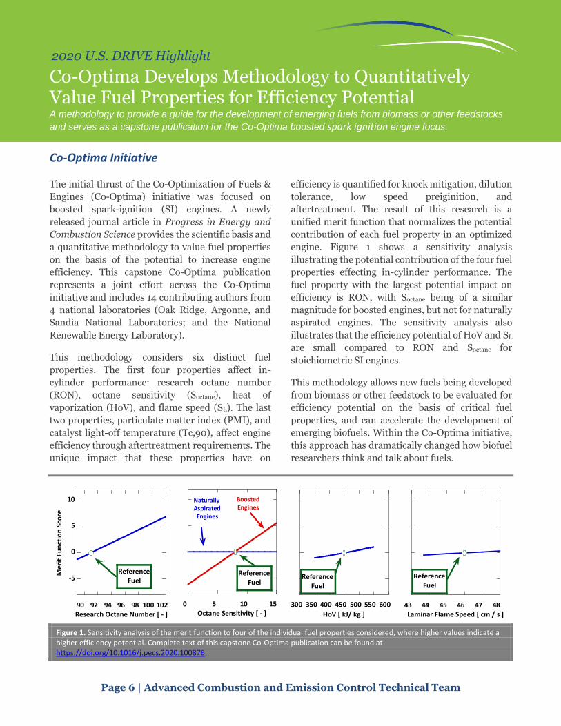
This methodology considers six distinct fuel
properties. The first four properties affect in-
cylinder performance: research octane number
(RON), octane sensitivity (Soctane), heat of
vaporization (HoV), and flame speed (SL). The last
two properties, particulate matter index (PMI), and
catalyst light-off temperature (Tc,90), affect engine
efficiency through aftertreatment requirements. The
unique impact that these properties have on
efficiency is quantified for knock mitigation, dilution
tolerance, low speed preiginition, and
aftertreatment. The result of this research is a
unified merit function that normalizes the potential
contribution of each fuel property in an optimized
engine. Figure 1 shows a sensitivity analysis
illustrating the potential contribution of the four fuel
properties effecting in-cylinder performance. The
fuel property with the largest potential impact on
efficiency is RON, with Soctane being of a similar
magnitude for boosted engines, but not for naturally
aspirated engines. The sensitivity analysis also
illustrates that the efficiency potential of HoV and SL
are small compared to RON and Soctane for
stoichiometric SI engines.
This methodology allows new fuels being developed
from biomass or other feedstock to be evaluated for
efficiency potential on the basis of critical fuel
properties, and can accelerate the development of
emerging biofuels. Within the Co-Optima initiative,
this approach has dramatically changed how biofuel
researchers think and talk about fuels.
Figure 1. Sensitivity analysis of the merit function to four of the individual fuel properties considered, where higher values indicate a higher efficiency potential. Complete text of this capstone Co-Optima publication can be found at https://doi.org/10.1016/j.pecs.2020.100876.
-5
0
5
10
90 92 94 96 98 100 102
Mer
it F
un
ctio
n S
core
Research Octane Number [ - ]
ReferenceFuel
0 5 10 15Octane Sensitivity [ - ]
Naturally Aspirated
Engines
BoostedEngines
ReferenceFuel
300 350 400 450 500 550 600
HoV [ kJ/ kg ]
ReferenceFuel
43 44 45 46 47 48Laminar Flame Speed [ cm / s ]
ReferenceFuel

Page 7 | Advanced Combustion and Emission Control Technical Team
2020 U.S. DRIVE Highlight
A Power Density High Efficiency Gasoline Lean Combustion Engine Develop a gasoline low temperature combustion system which shows low fuel consumption and low emissions without deteriorating vehicle performance.
General Motors LLC
The primary objective of this program is the
development and demonstration of a downsized boosted, lean, low temperature gasoline combustion (LTC) engine system capable of demonstrating a 15%-17% fuel economy improvement relative to a contemporary naturally aspirated stoichiometric combustion engine consistent with relevant emissions constraints and the use of marketplace gasolines. The program focused on maximizing internal combustion engine fuel economy potential by combining the benefits of downsized boosted engine technology with next-generation gasoline lean-burn, low temperature combustion.
General Motors successfully completed all technical deliverables through the end of the project. A summary of accomplishments during the project is stated below.
1. Developed homogeneous stoichiometric spark-ignition combustion and control for baseline reference.
2. Developed low temperature combustion and control including lean limit extension strategy during negative valve overlap (NVO) operation, stability improvement strategy during positive valve overlap (PVO) operation, LTC operating range extension strategy.
3. Developed combustion mode switching (transition) strategy including two-step cam lobe design, variable injection strategy to reduce combustion noise, and re-firing strategy after decel fuel cut-off (DFCO).
4. Develop emissions control strategy using low-cost passive selective catalytic reduction system.
5. The main enablers of this project are successful development of combustion phasing control strategy, noise reduction strategy during transient, mode switching strategy using physics-based control, and aftertreatment control strategy. In addition, the maximum extension of lean operation contributes to maximize fuel economy benefit (see Figure 1.
86% of Federal Test Procedure [FTP] cycle was operated in lean condition).
T
Figure 1. Variation of combustion mode during FTP cycle.
Summary of tail-pipe emissions of LTC engine obtained from hot FTP and cold FTP are shown in Figure 2. The project team met the SULEV 30 target for both hot FTP and cold FTP cycle test while achieving fuel economy gain of 20.5% and 18.9% respectively using degreened catalysts.
T
Figure 2. Summary of tail-pipe emissions results obtained
from hot FTP cycle and cold FTP cycle test including fuel
economy gain (averaged results of 3 measurements).
These technologies are part of a solution that is
technically capable of introduction in the U.S. in the
near- to medium-term and is consistent with current
and anticipated future emission standards.
Page 8 | Advanced Combustion and Emission Control Technical Team
2020 U.S. DRIVE Highlight
Study Affirms Fuels with High Octane Sensitivity Outper-form those with Low Sensitivity at High Loads and Speeds Increasing octane sensitivity for fuels with RON ≥ 97 does not cause MON to become limiting in boosted engines.
Oak Ridge National Laboratory
Fuel anti-knock properties including research
octane number (RON), motor octane number
(MON), and the difference between RON and MON,
known as octane sensitivity (OS), are key fuel
characteristics that strongly influence spark ignition
engine efficiency. Increasing RON and OS can
improve engine efficiency by allowing the use of
increased compression ratio. Increasing OS comes at
the expense of lower MON, and there is not a full
understanding of required MON levels at higher
compression ratios. This study aimed to provide
information about high load and high speed
performance when MON is decreased relative to
RON to provide greater OS for fuels with RON ≥ 97.
Fuels with RON ≥ 97 and OS ≥ 10 and isooctane, a
fuel with OS = 0, were used in a turbocharged engine
with a compression ratio of 12.4. The team compared
maximum brake mean effective pressure (BMEP)
and combustion phasing (CA50) when these fuels
were used (Figure 1). At speeds up to 4,000 RPM, the
97 RON fuels with OS greater than 10 provided more
advanced CA50, by up to 8 crank angle degrees
(CAD). The more advanced CA50 provides greater
engine efficiency and can enable greater BMEP. The
experimental data were augmented by results using
kinetic modeling to show that the high OS fuels
continue to provide improved performance at up to
6,000 revolutions per minute (RPM) and when
intake air temperatures rise to as high as 100°C, as
might be experienced during high-power events in
high-temperature ambient conditions. Thus, even at
the high speed engine operating conditions with
elevated operating temperatures, fuels with high OS
continued to be beneficial for engine efficiency and a
MON limitation was not encountered for fuels with
RON and MON consistent with a premium or higher
fuel grade.
Figure 1. Fuels with high OS enabled more advanced combustion phasing and thus higher efficiency at 4,000 RPM and 16 bar BMEP conditions compared to isooctane, which has OS = 0. Differing fuel chemistry produces different CA50 phasing at the same OS, pointing to the importance of chemical kinetics during the combustion process.
0
5
10
15
20
25
30
35
Isooctane Co-OptimaAromatic
DiisobutyleneBlend
Co-OptimaE30
E20 Blend
Co
mb
ust
ion
Ph
asin
g (C
A5
0, C
AD
ATD
C)
Engine Efficiency Improvement
RON 100 98.0 98.2 98.3 101.3MON 100 87.3 88.0 87.6 88.8OS 0 10.7 10.2 10.7 12.5
Page 9 | Advanced Combustion and Emission Control Technical Team
2020 U.S. DRIVE Highlight
Highly Efficient Palladium PNA for NOx Control Enabling SULEV 30 Emission Compliance Adsorbate-controlled location of atomically dispersed Pd(II) in Pd/FER passive NOx adsorbers determines high activity and stability.
Pacific Northwest National Laboratory, BASF
Eliminating toxic nitrogen oxides (NOx) emissions
from internal combustion engines is necessary for
societal and legislative purposes. Ammonia selective
catalytic reduction (NH3-SCR) technology
successfully removes NOx at greater than 200ºC
using sacrificial ammonia to drive the reaction and
was implemented by BASF at large scale via Cu/SSZ-
13. However, at low temperatures, less than 180ºC,
e.g., during vehicle cold start, current catalysts are
incapable of performing this reaction effectively.
Furthermore, ammonia cannot be delivered
successfully to the catalyst at temperatures less than
180ºC with urea as the source. To address the low-
temperature cold start problem, palladium
(Pd)/zeolite materials were introduced as passive
NOx adsorbers (PNA).
PNAs exhibit complex chemistry on single-atom Pd
sites that must be further understood under
practically relevant exhaust gas feeds if PNAs are to
be a viable option for NOx control. Despite their
promise, there remains a formidable challenge for
these materials to (1) be hydrothermally stable to
800°C, (2) perform well with elevated levels of
carbon monoxide (CO) during cold start, and (3)
exhibit excellent performance during consecutive
PNA cycles and be regenerable.
Pacific Northwest National Laboratory (PNNL) and
BASF researchers have discovered that treatment
with high CO concentration results in a superior
Pd/ferrierite (FER) zeolite PNA that yields greater
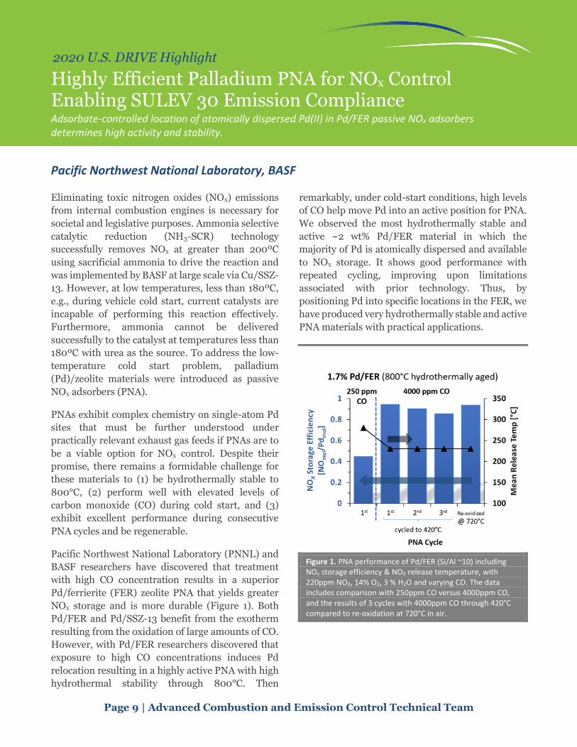
NOx storage and is more durable (Figure 1). Both
Pd/FER and Pd/SSZ-13 benefit from the exotherm
resulting from the oxidation of large amounts of CO.
However, with Pd/FER researchers discovered that
exposure to high CO concentrations induces Pd
relocation resulting in a highly active PNA with high
hydrothermal stability through 800°C. Then
remarkably, under cold-start conditions, high levels
of CO help move Pd into an active position for PNA.
We observed the most hydrothermally stable and
active ~2 wt% Pd/FER material in which the
majority of Pd is atomically dispersed and available
to NOx storage. It shows good performance with
repeated cycling, improving upon limitations
associated with prior technology. Thus, by
positioning Pd into specific locations in the FER, we
have produced very hydrothermally stable and active
PNA materials with practical applications.
Figure 1. PNA performance of Pd/FER (Si/Al ~10) including NOx storage efficiency & NOX release temperature, with 220ppm NOX, 14% O2, 3 % H2O and varying CO. The data includes comparison with 250ppm CO versus 4000ppm CO, and the results of 3 cycles with 4000ppm CO through 420°C compared to re-oxidation at 720°C in air.

Electrical and Electronics

Page 11 | Electrical and Electronics Technical Team
2020 U.S. DRIVE Highlight
High-Speed Hybrid Reluctance Motor Utilizing Anisotropic Materials Three motor variants demonstrate potential for heavy rare-earth-free traction motors.
General Motors
High cost and volatility are driving efforts to
decrease reliance on the critical heavy rare-earth
(HRE) materials used in traction drive applications.
To that end, General Motors (GM) developed three
variants of HRE-free electric motors: an HRE-free
permanent magnet reluctance motor, a synchronous
reluctance motor utilizing small HRE-free
permanent magnets, and an induction motor with
inserted copper bars and cast aluminum end rings.
The designs take advantage of advanced magnet
technologies and new topologies to improve
mechanical strength and achieve power targets. The
motors were designed for primary or secondary
traction applications, depending on the topology.
Variant 1 achieved performance comparable to HRE-
containing permanent magnet motors through
optimized topology, as well as validated HRE-free
magnets, focusing on achieving energy products and
demagnetization resistance comparable to those of
HRE-containing magnets. Demagnetization testing
demonstrated the motor’s robustness to currents
and temperatures exceeding expected vehicle
conditions, a key challenge to the use of HRE-free
magnets. The Variant 1 motor also showed the best
capability of meeting the U.S. DRIVE technology
targets, owing to the high power density of the
permanent magnet motor and the potential cost
reductions enabled by the removal of HREs.
Performance of the Variant 1 motor at the nominal
350 volt (V) is shown in Figure 1.
Variant 2 exhibited high efficiency in high-speed
regions because of the low high-speed losses, an
important consideration for secondary traction
applications, and significantly thrifted on magnet
mass to reduce cost.
Variant 3 contained copper bars within the induction
rotor to reduce losses compared to cast aluminum,
while using cast aluminum end rings to reduce the
cost and mass of the rotor. Researchers focused on
optimizing the copper–aluminum interface, which is
prone to forming brittle intermetallic compounds.
Prototypes of each motor variant were built and
tested for performance, mechanical strength, and
demagnetization resistance (Variants 1 and 2 only),
with torque and power close to predicted values.
Table 1 provides the testing results.
Figure 1. Performance results of the Variant 1 motor, tested at 350V.
Table 1. Comparison of each motor variant. Packaging size was selected based on the intended application of each motor variant.

Page 12 | Electrical and Electronics Technical Team
2020 U.S. DRIVE Highlight
Experimentally Confirmed High Thermal Performance of the Novel Dielectric Liquid Cooling Concept Concept predicted to enable achieving power density of 100 kW/L, a U.S. Department of Energy 2025 target.
National Renewable Energy Laboratory
The National Renewable Energy Laboratory (NREL)
has developed a novel cooling concept that is
predicted to provide better thermal performance
than current automotive technology, thereby
increasing the power density of electronics to as
much as 100 kW/L. Higher power density translates
into better performance but is limited by heat
generated during operation. NREL’s cooling concept
uses single-phase dielectric liquid jets impinging on
a densely finned heat spreader surface to cool the
devices indirectly. Although dielectric fluids have
poor properties (e.g., high viscosity at low
temperatures) compared to the coolant commonly
used in automotive applications, these liquid
materials allow for a redesign of the power module
to eliminate the ceramic dielectric layer, which can
lower overall thermal resistance, improve reliability,
and reduce cost. Dielectric fluids also offer the ability
to cool the electrical interconnections directly, which
can decrease capacitor and gate driver temperatures
and enable more compact packaging (i.e., high
power density).
NREL used computational fluid dynamics (CFD)
modeling to design a jet impingement-based
dielectric fluid cooling system. Modeling predicts a
low junction-to-fluid thermal resistance (21
mm2·K/W) and low pumping power (0.15 W), which
are 50% and 80% lower, respectively, than the 2015
BMW i3. A prototype of the cooling concept was
fabricated out of lightweight and low-cost plastics
using additive manufacturing methods (Figure 1).
Researchers conducted experiments to measure the
heat exchanger thermal resistance and pressure
drop at various fluid flow rates and temperatures
using Alpha 6 fluid, a dielectric and heat transfer oil
for applications with very high operating
temperatures. The experiments confirmed the low
thermal resistance and low pumping power
requirements predicted by the CFD model (Figure 1).
The good match between the modeling and
experimental results confirmed the model’s
predictive abilities. NREL then used the model to
evaluate several dielectric fluids (AC-100 and
automatic transmission fluid) at various fluid flow
rates and temperatures (-40°C to 70°C). The model
results predict that using AC-100 at -40°C can
provide both a lower junction-to-fluid thermal
resistance and lower pumping power requirements
compared with the 2015 BWM i3 at 65°C. These
results suggest that dielectric fluid viscosity
concerns may not be an issue if the correct low-
viscosity fluid is selected and combined with a low-
pressure-drop heat exchanger. Next steps include
modeling a double-sided concept and experimental
implementation within a package/module.
Figure 1. Model results showing temperature contours and fluid streamlines (top left); image comparing the cooling system’s size to that of a cell phone (top right); graph showing a good match between model and experimental results at various fluid flow rates and temperatures (bottom).
Page 13 | Electrical and Electronics Technical Team
2020 U.S. DRIVE Highlight
Graphite Embedded High-Performance Insulated Metal Substrate for Wide Bandgap-Based Power Modules Developed and experimentally validated steady-state and transient thermal performance of graphite embedded insulated metal substrates to replace conventional direct bonded copper solutions.
Oak Ridge National Laboratory
A high-performance substrate was developed in
collaboration with Henkel and Momentive to
provide high-performance thermal management for
wide bandgap (WBG) power modules. With
increased power loss density in a WBG-based
converter and reduced die size in power modules,
thermal management of power devices must be
optimized for high performance. The proposed
graphite-embedded substrate’s electrical
performance is validated with static and dynamic
thermal characterization. Using graphite-embedded
substrates instead of direct bonded copper (DBC)
substratse, the junction-to-case thermal resistance
of silicon carbide (SiC) MOSFETs can be reduced up
to 17%, and device current density can be increased
by 10%, regardless of the thermal management
strategy used to cool the substrate. Reduced
transient thermal impedance of up to 40% due to the
increased heat capacity is validated in transient
thermal simulations and experiments. The half-
bridge power module's electrical performance is
evaluated for on-state resistance, switching
performance, and switching loss at three different
junction temperature conditions. The proposed
substrate has minimal impact on conduction and
switching performance of SiC MOSFETs.
The insulated metal substrate with thermal
pyrolythic graphite (IMSwTPG) is formed by an
insulated metal substrate (IMS) with multiple
conductive and dielectric layers to accommodate the
half-bridge configuration for a typical power
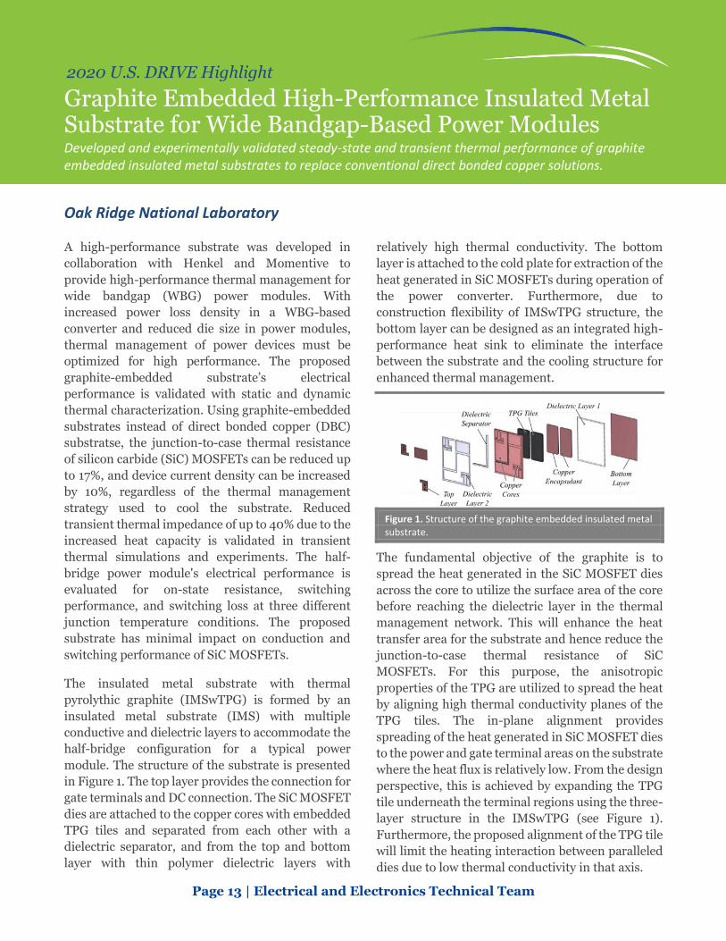
module. The structure of the substrate is presented
in Figure 1. The top layer provides the connection for
gate terminals and DC connection. The SiC MOSFET
dies are attached to the copper cores with embedded
TPG tiles and separated from each other with a
dielectric separator, and from the top and bottom
layer with thin polymer dielectric layers with
relatively high thermal conductivity. The bottom
layer is attached to the cold plate for extraction of the
heat generated in SiC MOSFETs during operation of
the power converter. Furthermore, due to
construction flexibility of IMSwTPG structure, the
bottom layer can be designed as an integrated high-
performance heat sink to eliminate the interface
between the substrate and the cooling structure for
enhanced thermal management.
Figure 1. Structure of the graphite embedded insulated metal substrate.
The fundamental objective of the graphite is to
spread the heat generated in the SiC MOSFET dies
across the core to utilize the surface area of the core
before reaching the dielectric layer in the thermal
management network. This will enhance the heat
transfer area for the substrate and hence reduce the
junction-to-case thermal resistance of SiC
MOSFETs. For this purpose, the anisotropic
properties of the TPG are utilized to spread the heat
by aligning high thermal conductivity planes of the
TPG tiles. The in-plane alignment provides
spreading of the heat generated in SiC MOSFET dies
to the power and gate terminal areas on the substrate
where the heat flux is relatively low. From the design
perspective, this is achieved by expanding the TPG
tile underneath the terminal regions using the three-
layer structure in the IMSwTPG (see Figure 1).
Furthermore, the proposed alignment of the TPG tile
will limit the heating interaction between paralleled
dies due to low thermal conductivity in that axis.

Page 14 | Electrical and Electronics Technical Team
2020 U.S. DRIVE Highlight
Co-Optimization of Boost Converter Reliability and Volumetric Power Density Research team uses a genetic algorithm to evaluate multi-objective trade space and optimize designs.
Sandia National Laboratories
Electric drive system performance is improved
through innovation in semiconductor devices, passive
component materials, and thermal management
technologies between power electronics and electric
motors. However, such tightly integrated systems
require comprehensive analysis to identify the factors
driving reductions in cost, volume, and weight while
simultaneously increasing efficiency and reliability.
Sandia National Laboratories has utilized multi-
objective optimization to analyze the reliability and
power density of a boost converter, a device that
increases voltage in an electric drive system. The
simplicity and ubiquity of the circuit make it a useful
test case for evaluating the optimization approach’s
accuracy. Sandia employed a genetic algorithm—a
population-based evolutionary search technique—to
investigate design trade-offs between various
component materials and cooling techniques.
Figure 1 depicts pareto-optimal solution sets that
evaluate power density and mean time between
failure (MTBF) (the predicted time between inherent
system failures) for a 5 kW boost converter using
different magnetic component types. The figure
Figure 1. Pareto solution evaluating Kool Mµ, High Flux, and Molypermalloy Powder (MPP) and the prototypes with different inductors denoted as P1, P2, and P3.
Figure 2. Picture of the hardware prototype with the High Flux core design, P3.
illustrates the trade-offs due to the varying magnetic
properties and loss characteristics in different
inductor core materials. Moreover, similar
approaches have been taken for cooling
mechanisms, semiconductor devices, and capacitor
materials.
Figure 2 shows a hardware prototype that was
constructed to demonstrate and verify the design
operating points. Figure 3 illustrates good
agreement between the experimental results and the
simulated behavior of the converter.
This work provides a foundational platform that can
be used to optimize additional power converters, as
well as trade-offs in thermal management due to the
use of different device substrate materials.
Figure 3. Measured waveforms of the 5 kW boost converter operation with input of 400 volt (V )and output of 500V for the High Flux design, P3

Electrochemical Energy Storage

Page 16 | Electrochemical Energy Storage Technical Team
2020 U.S. DRIVE Highlight
A Lithium-ion Battery Electrolyte Recycling Process Recovering electrolytes during Li-ion battery recycling could have a positive impact on revenue and therefore make recycling more viable and profitable. ReCell has developed a recycling process that can recover the LiPF6 salt and some other electrolyte components for re-use, with resulting performance similar to that of a baseline electrolyte.
Argonne National Laboratory
Creating a profitable lithium (Li)-ion battery
recycling process will enable a comprehensive
recycling program and reduce the cost of batteries
using these recycled materials. Maximizing revenue
requires that as many components as possible be
recovered. One such opportunity is to recover the
electrolyte and its relatively expensive Li salt, LiPF6.
A recycling process for end-of-life Li-ion batteries
typically starts with shredding (Figure 1a). At this
point the recovered shredded material is coated with
the liquid electrolyte. This electrolyte must be
removed before further processing because it
contains LiPF6 that can react with other materials.
Utilizing a low boiling point carbonate solvent such
as dimethyl carbonate or diethyl carbonate, the
electrolyte is removed from the solid shreds. The
recovered materials contain a complex mixture of
carbonates and decomposition products as can be
seen in Figure 1b.
The recovered electrolyte is too dilute for use, so that
material was concentrated via evaporation.
Evaporation removed many of the contaminants
from the electrolyte. After the evaporation process a
new electrolyte was formulated using the remaining
ethylene carbonate and LiPF6. After performing this
process on an end-of-life commercial battery, the
recycled electrolyte was tested in a full cell to see if it
performed as well as a pristine electrolyte. The
resulting cycling data are shown in Figure 1c. The
recycled electrolyte shows more rapid initial capacity
fade, but in longer term cycling it has a lower fade
rate than the pristine electrolyte. The improvements
are likely due to trace levels of additives, such as
LiPO2F2, that remain after recovery. These data
indicate that electrolyte can be recovered from spent
Li-ion batteries with performance comparable to the
virgin electrolyte.
Figure 1. (a) Schematic diagram of a direct recycling process. (b) 1H and 19F NMR spectra of recovered electrolyte from a commercial cell. (c) Cycling of LiNi0.33Mn0.33Co0.33O2 versus graphite using a recycled electrolyte and a baseline electrolyte.
Page 17 | Electrochemical Energy Storage Technical Team
2020 U.S. DRIVE Highlight
Highly Uniform Dopant Distributions Improve Life in High-Energy Nickel-Rich Cathodes Novel processing utilizing atomic layer deposition provides a higher degree of control over dopant distribution compared to typical routes—resulting in enhanced electrochemical performance.
Argonne National Laboratory
Layered LiNiO2 and its substituted derivatives
(>~90% nickel [Ni]) have been studied for many
years as lithium-ion cathodes due to their high
energy densities and low cobalt contents. However,
thermal and structural instabilities make it clear that
modifications (i.e., dopants) are critical to using
these oxides in commercial cells. Though
compositions such as aluminum (Al)-containing
NCAs have found success, recent work from Argonne
National Laboratory (ANL) has shown that even
NCA-type commercial oxides can have
inhomogeneous distributions of Al.1 Therefore,
improvements in Ni-rich oxide performance might
be expected through more advanced processing.
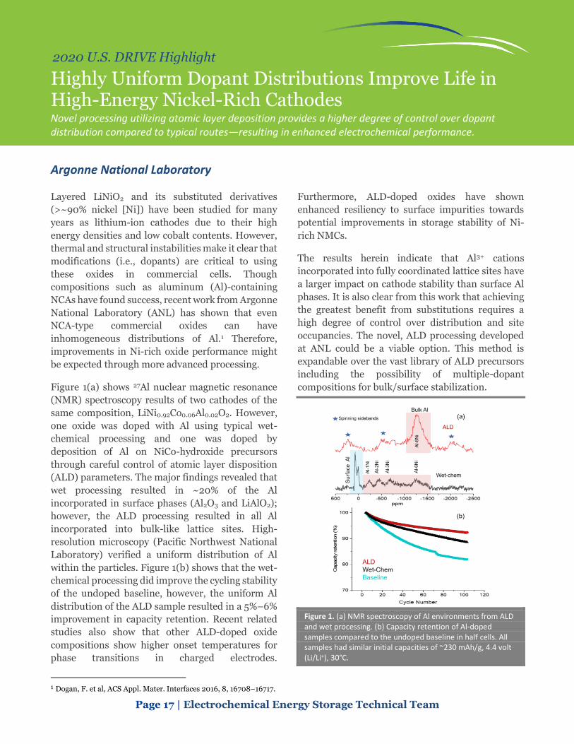
Figure 1(a) shows 27Al nuclear magnetic resonance
(NMR) spectroscopy results of two cathodes of the
same composition, LiNi0.92Co0.06Al0.02O2. However,
one oxide was doped with Al using typical wet-
chemical processing and one was doped by
deposition of Al on NiCo-hydroxide precursors
through careful control of atomic layer disposition
(ALD) parameters. The major findings revealed that
wet processing resulted in ~20% of the Al
incorporated in surface phases (Al2O3 and LiAlO2);
however, the ALD processing resulted in all Al
incorporated into bulk-like lattice sites. High-
resolution microscopy (Pacific Northwest National
Laboratory) verified a uniform distribution of Al
within the particles. Figure 1(b) shows that the wet-
chemical processing did improve the cycling stability
of the undoped baseline, however, the uniform Al
distribution of the ALD sample resulted in a 5%–6%
improvement in capacity retention. Recent related
studies also show that other ALD-doped oxide
compositions show higher onset temperatures for
phase transitions in charged electrodes.
1 Dogan, F. et al, ACS Appl. Mater. Interfaces 2016, 8, 16708−16717.
Furthermore, ALD-doped oxides have shown
enhanced resiliency to surface impurities towards
potential improvements in storage stability of Ni-
rich NMCs.
The results herein indicate that Al3+ cations
incorporated into fully coordinated lattice sites have
a larger impact on cathode stability than surface Al
phases. It is also clear from this work that achieving
the greatest benefit from substitutions requires a
high degree of control over distribution and site
occupancies. The novel, ALD processing developed
at ANL could be a viable option. This method is
expandable over the vast library of ALD precursors
including the possibility of multiple-dopant
compositions for bulk/surface stabilization.
Figure 1. (a) NMR spectroscopy of Al environments from ALD and wet processing. (b) Capacity retention of Al-doped samples compared to the undoped baseline in half cells. All samples had similar initial capacities of ~230 mAh/g, 4.4 volt (Li/Li+), 30°C.

Page 18 | Electrochemical Energy Storage Technical Team
2020 U.S. DRIVE Highlight
Pushing the Limits of Rechargeable Lithium Metal Battery Cycle Life and Energy Density Battery500 Consortium researchers integrated materials science, electrochemistry, and engineering to extend the cycle life of high-energy lithium metal batteries.
Battery500 Consortium
The Battery500 Consortium pushes the frontier of
advanced electrode and electrolyte materials and
develops strategies to integrate materials science,
electrochemistry, and cell engineering in high-
energy rechargeable lithium (Li) metal batteries to
achieve more than 400 cycles in prototype 350
Wh/kg pouch cells (2 Ah) (Figure 1a–b).
To decelerate the continuous side reactions in Li
metal batteries and the consumption rate of both
lean electrolytes and thin Li in realistic pouch cells,
a localized concentrated electrolyte consisting of
1.54M lithium bis(fluorosulfonyl)imide (LiFSI) in
1,2-dimethoxyethane (DME) and 1,1,2,2-
tetrafluoroethyl-2,2,3,3-tetrafluoropropyl ether
(TTE) has been developed to minimize the formation
of “dead” Li formed during cycling and improve the
efficiency of Li deposition/stripping. The properties
of solid electrolyte interphase layers formed between
the newly developed electrolyte and Li metal are also
improved, minimizing the amount of electrolyte
irreversibly consumed during cycling.
To accelerate mass transport, high mass-loading
cathode architectures with controlled porosities are
coupled with a Li anode (Figure 1c-d) to increase Li+
diffusion and reduce opportunities for spiky
microstructures of Li to form during cycling. The
synthesis conditions and electrochemical properties
of high nickel manganese cobalt oxide cathodes are
investigated to balance capacity and cycling stability.
A new, user-friendly software for designing Li metal
batteries has been developed, see
https://www.pnnl.gov/technology/li-batt-
design.app, to derive the key cell parameters needed
to achieve the desired cell-level gravimetric and
volumetric energy densities. Standard Battery500
coin cell testing protocols have been developed and
implemented to compare and select the materials or
approaches developed within the Consortium and
from collaborators. The Consortium has used
advanced in situ and ex situ characterization
techniques—such as cryogenic electron microscopy
and in situ X-ray diffraction—to monitor and
quantify the chemical and structural changes of
electrodes, providing feedback on pouch-cell-level
design.
New knowledge gathered from cell degradation
mechanisms, as well as the combination of cell
design, compatible interfaces, and uniform initial
pressure applied on the cell, 26.7 psi, synergistically
extends the stable cycling of 350 Wh/kg pouch cells
with 80% capacity retention after 430 cycles, Fig 1.
Figure 1. 350 Wh/kg pouch cells achieve more than 400 cycles. (a) Cell-level energy and capacity at different cycling. (b) Image of a 350 Wh/kg Li metal pouch cell developed at Pacific Northwest National Laboratory. (c) Structure of a LiNi0.6Mn0.2Co0.2O2 cathode coated on both sides of aluminum current collector. (d) One of the Li anodes incorporated in the pouch cell.
Page 19 | Electrochemical Energy Storage Technical Team
2020 U.S. DRIVE Highlight
Towards Higher-Energy Density via State-of-Charge Gradient Determination in Thick Electrodes Researchers used synchrotron diffraction methods to quantify the vertical inhomogeneity in thick cathode films to understand the origin of the performance limitations in this energy-dense electrode.
Brookhaven National Laboratory
One generally applicable route for enhancing the
energy density of lithium-ion batteries (thereby
increasing the range of electric vehicles) is using
thicker electrode (anode and cathode) films.
However, the specific capacity and rate performance
of thick electrodes is reduced due to limitations in
the transport of ions and/or electrons perpendicular
to the plane of the film. If the precise origin of these
transport limitations can be understood, it might be
possible to rationally design thicker electrodes that
deliver higher energy densities than present
batteries while still meeting the other performance
demands of electric vehicles.
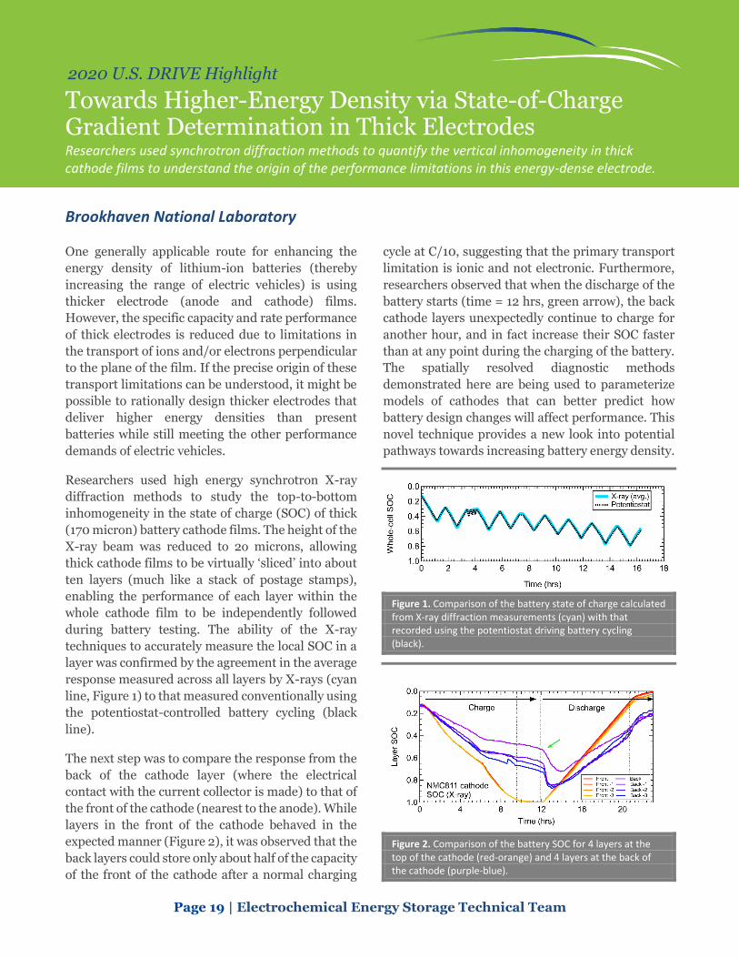
Researchers used high energy synchrotron X-ray
diffraction methods to study the top-to-bottom
inhomogeneity in the state of charge (SOC) of thick
(170 micron) battery cathode films. The height of the
X-ray beam was reduced to 2o microns, allowing
thick cathode films to be virtually ‘sliced’ into about
ten layers (much like a stack of postage stamps),
enabling the performance of each layer within the
whole cathode film to be independently followed
during battery testing. The ability of the X-ray
techniques to accurately measure the local SOC in a
layer was confirmed by the agreement in the average
response measured across all layers by X-rays (cyan
line, Figure 1) to that measured conventionally using
the potentiostat-controlled battery cycling (black
line).
The next step was to compare the response from the
back of the cathode layer (where the electrical
contact with the current collector is made) to that of
the front of the cathode (nearest to the anode). While
layers in the front of the cathode behaved in the
expected manner (Figure 2), it was observed that the
back layers could store only about half of the capacity
of the front of the cathode after a normal charging
cycle at C/10, suggesting that the primary transport
limitation is ionic and not electronic. Furthermore,
researchers observed that when the discharge of the
battery starts (time = 12 hrs, green arrow), the back
cathode layers unexpectedly continue to charge for
another hour, and in fact increase their SOC faster
than at any point during the charging of the battery.
The spatially resolved diagnostic methods
demonstrated here are being used to parameterize
models of cathodes that can better predict how
battery design changes will affect performance. This
novel technique provides a new look into potential
pathways towards increasing battery energy density.
Figure 1. Comparison of the battery state of charge calculated from X-ray diffraction measurements (cyan) with that recorded using the potentiostat driving battery cycling (black).
Figure 2. Comparison of the battery SOC for 4 layers at the top of the cathode (red-orange) and 4 layers at the back of the cathode (purple-blue).
Page 20 | Electrochemical Energy Storage Technical Team
2020 U.S. DRIVE Highlight
Lithium-Ion Cell Brings Extreme Fast Charging Closer to Reality for Electric Vehicles A 35Ah lithium-ion pouch cell has been developed using advanced cell materials that can be charged in 10-minutes reproducibly more than 850 times.
Microvast, Inc.
The convenience of quickly refilling a car is one
advantage of gasoline vehicles compared to fully
electric alternatives (although home charging is
arguably an advantage of electric vehicles [EV]).
While fast charging EVs presents challenges to
electricity grids and charging stations, perhaps the
most difficult hurdles to overcome are from the
lithium-ion (Li-ion) battery cell itself. During fast
charge the high currents typically cause higher
temperatures and uneven chemical reaction rates
within the cells. These operating conditions in turn
lead to faster cell degradation. Further, these
degradations typically become more intense as the
Li-ion cell energy density is increased.
One of the most straightforward ways to change a Li-
ion cell’s performance and energy density is by using
different materials. Cell component material
properties differ based on composition and physical
attributes, which in turn influences the cell’s
performance. It is especially important to improve
the cathode, the most expensive individual cell
component. Higher capacity cathodes lead to more
energy density, while improved properties slow cell
degradation and resistance increases. Using the full
concentration gradient (FCG) cathode technology
that Microvast is developing for commercialization,
cathodes with tailored surfaces that are more stable
to fast charge effects were prepared. The FCG
technology allows engineers to change the atomic
composition of metals throughout the cathode
particle, placing more desirable metal oxide
combinations at locations most vulnerable to
degradation. Also, as the nickel content of the FCG
cathode is increased the prototype cell’s C/3 energy
density could be improved.
Initially, a 200 Wh/kg cell was the highest energy
density cell made by Microvast that could achieve
the 500 10-minute charging goals. Steadily that
number has improved as the cathode was optimized,
eventually reaching 240 Wh/kg as the base (0.33C)
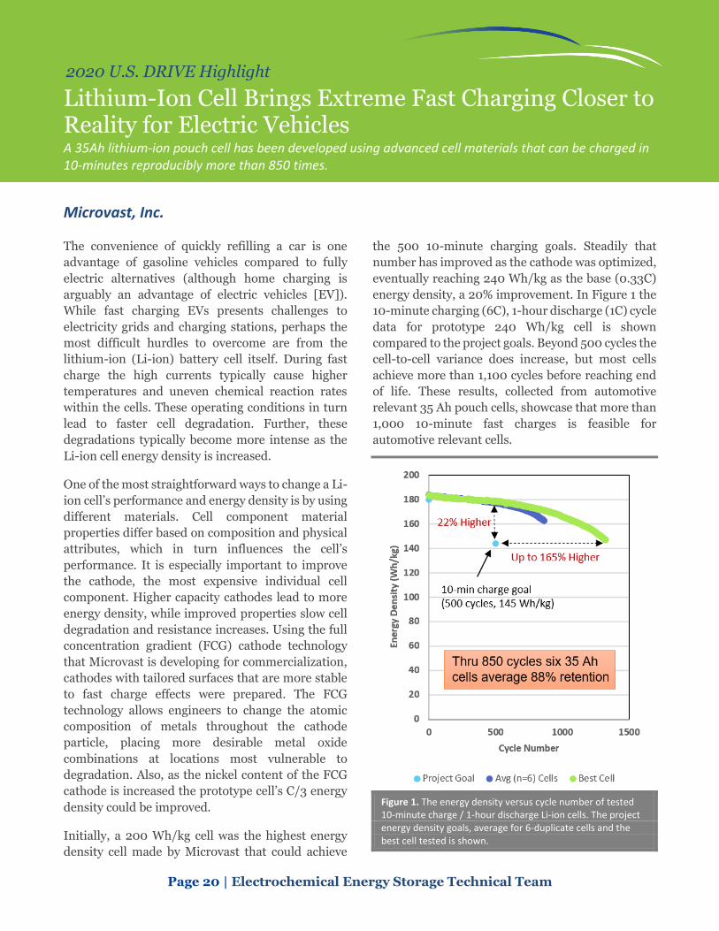
energy density, a 20% improvement. In Figure 1 the
10-minute charging (6C), 1-hour discharge (1C) cycle
data for prototype 240 Wh/kg cell is shown
compared to the project goals. Beyond 500 cycles the
cell-to-cell variance does increase, but most cells
achieve more than 1,100 cycles before reaching end
of life. These results, collected from automotive
relevant 35 Ah pouch cells, showcase that more than
1,000 10-minute fast charges is feasible for
automotive relevant cells.
Figure 1. The energy density versus cycle number of tested 10-minute charge / 1-hour discharge Li-ion cells. The project energy density goals, average for 6-duplicate cells and the best cell tested is shown.
Page 21 | Electrochemical Energy Storage Technical Team
2020 U.S. DRIVE Highlight
Protocol for Early Assessment of Calendar Life and Faster Technology Development in Silicon-Based Anodes Holding the voltage at top of charge for a silicon cell with excess lithium from the cathode can help predict calendar life with a dramatic reduction in required test time.
Silicon Consortium Project Team (Argonne National Laboratory, National Renewable
Energy Laboratory, Oak Ridge National Laboratory, Sandia National Laboratories,
Pacific Northwest National Laboratory, and Lawrence Berkeley National Laboratory).
Silicon (Si) anodes offer the prospect of lithium ion
(Li-ion) cells with 30% improvement in energy
compared to today’s graphite anode cells. However,
their short calendar life (2-3 years) is a major hurdle
to commercialization. Calendar life testing of battery
cells is traditionally carried out by aging cells for
multi-month-long timeframes. Thus, development
of a short-timeframe (days instead of months/years)
calendar life test could enable faster feedback and
development of new and improved materials.
The new electrochemical test provides a mechanism
that researchers and developers can use to assess the
progress in the development of Si-based negative
electrodes within a short timeframe of two weeks.
This test makes use of a constant voltage hold in a Li-
excess full cell containing a Li iron phosphate
counter electrode with a flat voltage output. The
current passed during the voltage hold is a measure
of the reaction rate of lithium consumption at the Si
anode through parasitic and irreversible
electrochemical reactions.
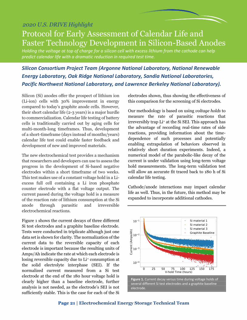
Figure 1 shows the current decays of three different
Si test electrodes and a graphite baseline electrode.
Tests were conducted in triplicate although just one
data set is shown for clarity. The normalization of the
current data to the reversible capacity of each
electrode is important because the resulting units of
Amps/Ah indicate the rate at which each electrode is
losing reversible capacity due to Li+ consumption at
the solid electrolyte interphase (SEI). If the
normalized current measured from a Si test
electrode at the end of the 180 hour voltage hold is
clearly higher than a baseline electrode, further
analysis is not needed, as the electrode’s SEI is not
sufficiently stable. This is the case for each of the Si
electrodes shown, thus showing the effectiveness of
this comparison for the screening of Si electrodes.
Our methodology is based on using voltage holds to
measure the rate of parasitic reactions that
irreversibly trap Li+ at the Si SEI. This approach has
the advantage of recording real-time rates of side
reactions, providing information about the time-
dependence of such processes and potentially
enabling extrapolation of behaviors observed in
relatively short duration experiments. Indeed, a
numerical model of the parabolic-like decay of the
current is under validation using long-term voltage
hold measurements. The long-term validation test
will allow an accurate fit traced back to 180 h of Si
calendar life testing.
Cathode/anode interactions may impact calendar
life as well. Thus, in the future, this method may be
expanded to incorporate additional cathodes.
Figure 1. Current decay versus time during voltage holds of several different Si test electrodes and a graphite baseline electrode.

Page 22 | Electrochemical Energy Storage Technical Team
2020 U.S. DRIVE Highlight
Electrolyte Development for Extreme Fast Charging (XFC) of Lithium-ion Batteries A high-performance electrolyte has been developed to increase lithium-ion mass transport during XFC, achieving 180 Wh/Kg energy density and maintaining > 80% energy density after 1000 XFC cycles.
Oak Ridge National Laboratory
Enabling fast charging of high energy density
lithium-ion (Li-ion) cells could dramatically increase
the widespread adoption of electric vehicles.
However, fast charging is limited by Li ion depletion
in the electrolyte and the accompanying Li plating
over graphite anodes. One of the solutions for
enabling extreme fast charging (XFC) while
retaining high battery energy can be achieved
through enhancing the Li ion mass-transport in
electrolytes such that enough Li ions are available for
intercalation in graphite.
Researchers at Oak Ridge National Laboratory
(ORNL) have developed high performance
electrolytes with optimized Li salt, solvents, and
additives. The electrolytes have both higher Li ion
conductivity and Li ion transference number,
compared to state-of-the-art electrolyte. The
electrolyte development is ideal for higher Li ion
transport and has been identified as a significant
step towards realizing cells with XFC capabilities.
The electrolytes were tested in 1.5Ah NMC622/
graphite pouch cells using the 6C (10 minute)
charging protocol. The cell with ORNL V2 electrolyte
retained 89% capacity after 500 XFC cycles (Figure
1), exceeding the targeted goal (80% after 500
cycles), and much better than the 64% retention for
the Gen2 baseline electrolyte (1.2 M LiPF6 in
EC:EMC 30:70 wt%). Continued cycling of the cells
show 80% capacity retention after 1000 cycles. The
cell can have an energy density of ~180 Wh/Kg
(when scaled up to 50 Ah), which meets the targeted
goal for energy density. After 1000 XFC cycles, the
cell still has 141 Wh/kg energy density. When the cell
was charged/discharged at C/3 after 1000 XFC
cycles, it can still deliver 193 Wh/kg.
Future work will include the understanding of high
voltage holding during XFC and optimizing
formation protocols for XFC of Li-ion cells.
Figure 1. Left, conductivities of ORNL V2 and Gen2 baseline electrolyte. Right, capacity retention versus cycling number under 6C (10 minutes) XFC protocol with 2-Ah cells filled with ORNL V2 and Gen2 baseline electrolyte.

Page 23 | Electrochemical Energy Storage Technical Team
2020 U.S. DRIVE Highlight
Sustainable Direct Recovery of Battery Materials from Manufacturing Scraps An environmentally friendly solvent-based separation process is developed to efficiently recover electrode materials and metal foils with no damage or corrosion.
Oak Ridge National Laboratory
Lithium-ion (Li-ion) batteries are valuable and
recyclable, but recycling processes are costly.
Profitable recycling of Li-ion batteries will thus
depend on new process developments. Electrode
materials are tightly bonded to their respective metal
current collectors through polymeric binders. To
recover electrode materials, especially cathode
materials that represent the most recoverable value,
an efficient and damage-free separation process
needs to be developed to isolate electrode materials
from metal foils like aluminum (the cathode current
collector) and copper (the anode current collector).
Scientists at Oak Ridge National Laboratory (ORNL)
have developed a solvent-based separation process
to recover both electrode materials and metal foils
without any damage and corrosion. Novel electrode
recovery process based on a greener solvent,
ethylene glycol, enables the delamination of
electrode coatings from metal foils in few seconds
(Figure 1a). The recovered battery materials tested to
date, especially NMC cathodes, are damage-free in
terms of crystal structure and microstructure and
are equivalent to their pristine cathode counterparts
in terms of electrochemical performance (Figure 1b).
This separation process might be deployed in battery
manufacturing plants ensuring that the electrode
scraps (up to 10% of the total processed electrodes)
can be treated onsite safely and reprocessed as new
electrodes.
In addition to the reclamation of cathode materials,
recovery of other materials such as graphite and
metal foils provides an additional materials cost
saving. Reclaiming copper and aluminum could
greatly reduce emissions of sulfur oxides, nitrogen
oxides, and energy consumption. As shown in Figure
1a, the recovered metal foils show no sign of
corrosion or residues, providing a path for their
reuse in battery manufacturing and for lessening the
carbon footprint in mining and refining.
Furthermore, the recovered graphite from anode
scraps shows equivalent electrochemical
performance as the baseline graphite (Figure 1c).
This robust separation process operates at a low
temperature and is scalable. Ethylene glycol is a
commodity with low toxicity and has an annual
consumption of 20 million tons for use as antifreeze
and polymer precursor. Moreover, ethylene glycol
can be reused to close the recycling loop without
generating secondary waste. Overall, the ethylene
glycol-based separation is a sustainable electrode
recovery process that greatly advances battery
recycling.
Figure 1. (a) Photos showing the recovered electrode materials and metal foils. 1st and 4th charge-discharge profiles for the recovered and re-coated electrodes of (b) NMC622 and (c) graphite at C/10 rates.

Page 24 | Electrochemical Energy Storage Technical Team
2020 U.S. DRIVE Highlight
Development of Silicon-Based High-Capacity Anodes for Next-Generation Lithium-Ion Batteries
Micron-sized porous silicon anode and localized high concentration electrolytes enabled long term cycling of high-capacity silicon-based lithium-ion batteries.
Pacific Northwest National Laboratory
Porous silicon (Si) has been widely used to mitigate
pulverization of Si particles and accommodate
swelling during battery cycling. However, the large
surface area of these Si materials may lead to severe
reactions between lithiated Si and electrolyte. These
reactions lead to continuous growth of the solid
electrolyte interphase layer and short cycle life and
calendar life. Therefore, minimizing the surface area
of Si and finding a stable electrolyte are critical for
improved cycling and calendar life of Si-based
lithium-ion batteries.
Researchers from the U.S. Department of Energy’s
Pacific Northwest National Laboratory (PNNL) have
developed a stable Si anode based on micron sized
porous Si with heterogeneous coating layers. Porous
Si was first prepared by thermal decomposition of
SiO and subsequent etching. It was then treated at
low temperature to form an intermediate layer on
porous Si. The treated porous Si was coated with
carbon using petroleum pitch as carbon precursor.
Si/NMC532 coin cells using the porous Si-C have
demonstrated excellent performances using a
baseline electrolyte (1.2M LiPF6 in EC/EMC (3/7 in
wt) + 10% FEC). The cell retains 78% capacity after
400 cycles with a stabilized coulombic efficiency of
99.9%. The superior stability of the porous Si-C
anode can be attributed to 1) mitigated volume
expansion with sealed porosity; 2) improved overall
conductivity of the composite; and 3) the minimized
electrolyte penetration into the porous Si.
The stability of PNNL’s Si anode was also
demonstrated in Si/NMC622 pouch cells using a
carbonate electrolyte E1 (1.2 M LiPF6 in EC-PC-EMC
(1:3:6 by wt) + 1 wt% VC + 7 wt% FEC) as shown in
Figure 1a. The cells are cycled between 2.0 to 4.35
volt (V) with 0.5C for discharge and 0.7C for charge.
A capacity check cycle is done at every 50 cycles at
0.2C. The cell retains 88% capacity after 950 cycles.
To further improve life, PNNL researchers have
developed several localized high concentration
electrolytes (LHCE). These electrolytes have
significantly improved cycle life of Si/LiCoO2 pouch
cells between 2.75 to 4.35V as shown in Figure 1b
where the Si anode developed in PNNL is used. The
cells can retain 80% capacity in 1000 and almost
2000 cycles using carbonate electrolyte E1 and
PNNL’s LHCE electrolyte, respectively.
Thus, the porous Si as created via PNNL’s method
has potential to enable the next generation of high-
energy lithium batteries, while the LHC electrolyte
provides new understanding of electrolyte
functionality with Si anodes towards further
potential enhancements in Si anode capability.
Figure 1. (a) Cycling of Si/NMC622 cells using porous Si anode and carbonate electrolytes E1. (b) Cycling stability of Si/LiCoO2 cells using porous Si anode and different electrolytes.

Page 25 | Electrochemical Energy Storage Technical Team
2020 U.S. DRIVE Highlight
Synthesis of High-Performance Nickel-Rich Cathode Materials for High-Energy Batteries Researchers identified cost-effective approaches to synthesize high-performance cathode materials for next-generation lithium-ion batteries.
Pacific Northwest National Laboratory
Nickel (Ni)-rich cathodes are one of the most
promising materials for next-generation, high-
energy lithium (Li)-ion batteries, but it suffers from
moisture sensitivity, side reactions, and gas
generation during cycling. A single crystalline, Ni-
rich cathode may address the challenges present in
its polycrystalline counterpart by reducing phase
boundaries and materials surfaces; however,
synthesis of electrochemically active Ni-rich single
crystalline cathodes remains challenging. Ni-rich
cathodes require lower synthesis temperatures
because of their structural instability at high
temperatures, opposite to the high-temperature and
time-consuming calcination process needed to grow
single crystals.
Researchers at Pacific Northwest National
Laboratory (PNNL) recently identified two cost-
competitive synthesis routes (compared to
traditional single crystal synthesis methods) to
prepare single crystalline LiNi0.76Mn0.14Co0.1O2
(NMC76). The route used here is a molten salt one
using NaCl, the second is a solid-state approach
which is currently being further developed in
collaboration with Albemarle under a separate DOE
project. Figure 1 displays the cycling stability of
NMC76 at different cutoff voltages. All material
evaluations were conducted using high mass-loading
(>20 mg/cm2) single crystals in full coin cells with a
graphite anode. Between 2.7 and 4.2 volt (V) (versus
graphite), single crystalline NMC76 delivers 182.3
mAh/g discharge capacity at 0.1 C and retains 86.5%
of its original capacity after 200 cycles (Fig. 1A). As
expected, increasing the cutoff voltage improves the
capacity, but cell degradation is faster (Fig. 1B–C).
Fig. 1D–F compares the corresponding
morphologies of single crystals cycled at different
cutoff voltages. If charged to 4.2V (Fig. 1D), the
entire single crystal is well maintained. Increasing
the cutoff voltage to 4.3V results in some visible
gliding lines on the crystal surfaces (Fig. 1E). When
cut off at 4.4V, single crystals are “sliced” (Fig. 1F) in
parallel. Small cracks were also discovered cycled
between 2.7 and 4.4V. Although single crystalline
NMC76 as an entire particle is still intact (Fig. 1D–
F) even at high cutoff voltages, gliding is the major
mechanical degradation mode. PNNL researchers
have identified a critical crystal size of 3.5 m, below
which gliding and microcracking will not occur,
providing clues to further improve single crystal
performances in the future. This work has recently
been published in Science (December 10, 2020).
Figure 1. Cycling stability of single crystalline NMC76 in full cells between 2.7V and (A) 4.2V, (B) 4.3 V, and (C) 4.4 V vs. graphite. (D), (E), and (F) are the corresponding Scanning Electron Microscope images of the cycled single crystals in (A), (B), and (C), respectively.

Page 26 | Electrochemical Energy Storage Technical Team
2020 U.S. DRIVE Highlight
A New Electrolyte Solvent Molecule Enables Lithium Metal Batteries A synthesized solvent molecule, FDMB, is rationally designed, and the resulting single-salt, single-solvent, low-concentration electrolyte is shown to enable anode-free pouch cells.
Stanford University and SLAC National Accelerator Laboratory
Lithium (Li) metal batteries have been identified as
a next-generation battery, yet they are restrained by
poor performing electrolytes. Conventional
electrolytes fall short when used with Li metal
anodes, let alone anode-free Li-based batteries.
Previous electrolyte engineering reports improved
the cycling efficiency of Li metal anodes, but have
not completely addressed the following key
parameters: (1) high Coulombic efficiency (CE) to
minimize Li loss, including in the initial cycles; (2)
use of lean electrolyte and limited-excess Li
conditions for maximized specific energy; (3) high
oxidative stability towards high-voltage cathodes;
(4) reasonable salt concentration for cost-
effectiveness; and (5) high boiling point and non-
flammability for safety and processability.
This team reports a new electrolyte that shows
promise to meet the above requirements (Nature
Energy, 5, 526-533, 2020). Fluorinated 1,4-
dimethoxybutane (FDMB, Figure 1a), is paired with
1 M lithium bis(fluorosulfonyl)imide (LiFSI) in a
single-salt, single-solvent electrolyte formulation
(LiFSI/FDMB) to enable stable, high energy-density
Li metal batteries. The 1 M LiFSI/FDMB electrolyte
reveals a high CE (~99.52%) and fast activation
(Li|Cu half-cell CE ramps up to more than 99%
within 5 cycles) for Li-metal anodes. The Li|NMC
full cells with limited-excess Li retain 90% capacity
after 420 cycles with an average CE of 99.98%
(Figure 1b). Furthermore, anode-free Cu|NMC811
pouch cells achieve ~325Wh/kg whole-cell energy
density, while Cu|NMC532 pouch cells realize ~80%
capacity retention after 100 cycles at 20°C, which is
one of the best performances among the state-of-
the-art anode-free cells (Figure 1c). The 1M
LiFSI/FDMB electrolyte also enables fast discharge
capability in anode-free pouch cells, which magnifies
its potential application in the field of premium
energy storage applications (Figure 1d). Our rational
design concept for new electrolyte solvents provides
a promising path to viable high-energy Li metal
batteries and anode-free pouch cells with high
cyclability and processability and may aid in
advancing understanding for more widespread and
lower cost energy storage applications.
Figure 1. (a) Molecular structure of FDMB. (b-d) Cycling performance of Li metal batteries and anode-free pouch cells.
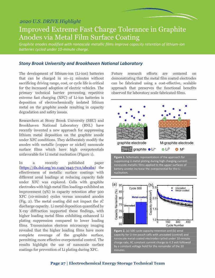
Page 27 | Electrochemical Energy Storage Technical Team
2020 U.S. DRIVE Highlight
Improved Extreme Fast Charge Tolerance in Graphite Anodes via Metal Film Surface Coating Graphite anodes modified with nanoscale metallic films improve capacity retention of lithium-ion batteries cycled under 10-minute charge.
Stony Brook University and Brookhaven National Laboratory
The development of lithium-ion (Li-ion) batteries
that can be charged in 10–15 minutes without
sacrificing driving range, cost, or cycle life is critical
for the increased adoption of electric vehicles. The
primary technical barrier preventing repetitive
extreme fast charging (XFC) of Li-ion batteries is
deposition of electrochemically isolated lithium
metal on the graphite anode resulting in capacity
degradation and safety issues.
Researchers at Stony Brook University (SBU) and
Brookhaven National Laboratory (BNL) have
recently invented a new approach for suppressing
lithium metal deposition on the graphite anode
under XFC conditions. They deliberately modify the
anodes with metallic (copper or nickel) nanoscale
surface films which have high overpotentials
unfavorable for Li metal nucleation (Figure 1).
In a recently published paper
(https://dx.doi.org/10.1149/1945-7111/abcaba) the
effectiveness of metallic surface coatings with
different areal loadings at reducing capacity fade
under XFC was explored. Cells with graphite
electrodes with high metal film loadings exhibited an
improvement (9%) in capacity retention after 500
XFC (10-minute) cycles versus uncoated anodes
(Fig. 2). The metal coating did not impact the 1C
discharge capacity. Li metal deposition quantified by
X-ray diffraction supported these findings, with
higher loading metal films exhibiting enhanced Li
plating suppression compared to lower loading
films. Transmission electron microscopy imaging
revealed that the higher loading films have more
complete coverage of the graphite surface,
permitting more effective overpotential control. The
results highlight the use of nanoscale surface
coatings for prevention of Li plating during XFC.
Future research efforts are centered on
demonstrating that the metal film coated electrodes
can be fabricated using a cost-effective, scalable
approach that preserves the functional benefits
observed for laboratory scale fabricated films.
Figure 1. Schematic representation of the approach for suppressing Li metal plating during high charging current: nanoscale metallic films applied to the upper surfaces of battery anodes increase the overpotential for the Li nucleation.
Figure 2. (a) 500 cycle capacity retention and (b) areal capacity for Li-ion pouch cells with uncoated (control) and nanoscale metal coated electrodes cycled under 10-minute charge rate, 6C constant current charge to 4.3 volt followed by a constant voltage hold for the remainder of the 10 minutes.

Page 28 | Electrochemical Energy Storage Technical Team
2020 U.S. DRIVE Highlight
A New Pathway to Higher Energy Density: Cobalt-Free Cathodes Enabled by 3D Targeted Doping Enhancing oxygen stability in low-cobalt layered oxide cathode materials by three-dimensional targeted doping.
University of California—Irvine
As high nickel cathode cell chemistries have reached
initial market penetration, a grand challenge for the
field is a quest for cobalt (Co)-free layered cathodes
to reduce the reliance on high-cost and toxic Co.
However, it is well known that LiNiO2 (LNO) has
high capacity but is thermally unstable at charged
state and has poor cycle life. To enhance its
performance requires structure-stabilizing elements
such as Co. Even though the instability of LNO seems
to render its use in a commercial cathode unlikely, it
shares many of the problems of currently employed
NMCs that have potential to be resolved using
specialized dopants or electrolytes targeting the
instability of the cathode/electrolyte interfaces.
The Low/No-cobalt project led by the University of
California (UC)—Irvine with team members from
Virginia Tech, UC Berkeley, and Pacific Northwest
National Laboratory have developed a three-
dimensional (3D) targeted doping technology that
combines surface and bulk doping with nanometer
precision. The team used computationally selected
surface dopants. They introduced theory-
rationalized bulk dopants to the interior of the
particles to further enhance oxygen stability and
inhibit deleterious phase transition in Co-free oxides
under high-voltage and deep-discharging operating
conditions.
As shown in Figure 1b, the team has enabled three-
dimensional targeted doping on the surfaces of the
cathode particle with nanometer precision. In the
meantime, the layered atomic structures are
preserved with nearly no secondary phase on the
surfaces. More importantly, the surface/bulk
titanium/magnesium doping significantly improve
the cycling performance of the Co-free and
extremely high-nickel chemistry
(LiNi0.96Ti0.02Mg0.02O2), reaching a cycle life of 400
cycles (2.5–4.4 volt vs. Li).
Future work will include full cell cycle life tests and
evaluating the cathode particles for improved
resilience to cracking or other damage.
Figure 1. (a-b) Structure and chemical imaging of the Co-free cathode particles. (c) 3D nano-electron-tomography imaging of the dopant distribution. (d-e) The electrochemical performance of the Co-free cathode materials.
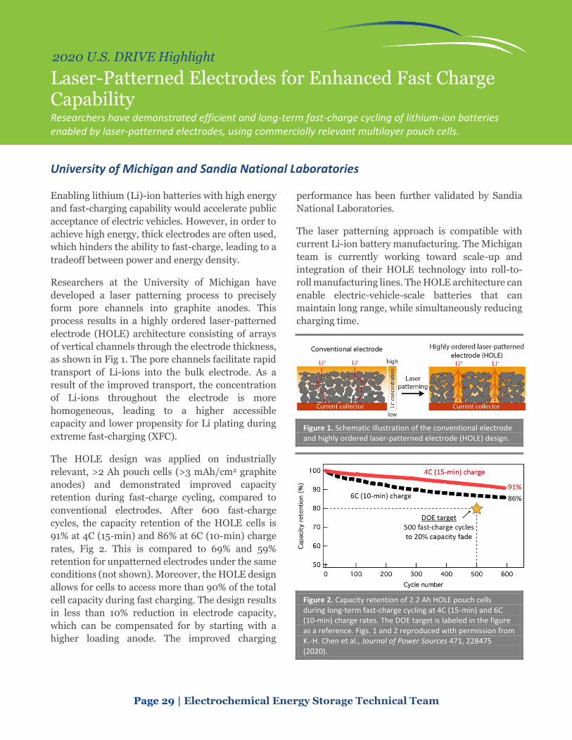
Page 29 | Electrochemical Energy Storage Technical Team
2020 U.S. DRIVE Highlight
Laser-Patterned Electrodes for Enhanced Fast Charge Capability Researchers have demonstrated efficient and long-term fast-charge cycling of lithium-ion batteries enabled by laser-patterned electrodes, using commercially relevant multilayer pouch cells.
University of Michigan and Sandia National Laboratories
Enabling lithium (Li)-ion batteries with high energy
and fast-charging capability would accelerate public
acceptance of electric vehicles. However, in order to
achieve high energy, thick electrodes are often used,
which hinders the ability to fast-charge, leading to a
tradeoff between power and energy density.
Researchers at the University of Michigan have
developed a laser patterning process to precisely
form pore channels into graphite anodes. This
process results in a highly ordered laser-patterned
electrode (HOLE) architecture consisting of arrays
of vertical channels through the electrode thickness,
as shown in Fig 1. The pore channels facilitate rapid
transport of Li-ions into the bulk electrode. As a
result of the improved transport, the concentration
of Li-ions throughout the electrode is more
homogeneous, leading to a higher accessible
capacity and lower propensity for Li plating during
extreme fast-charging (XFC).
The HOLE design was applied on industrially
relevant, >2 Ah pouch cells (>3 mAh/cm2 graphite
anodes) and demonstrated improved capacity
retention during fast-charge cycling, compared to
conventional electrodes. After 600 fast-charge
cycles, the capacity retention of the HOLE cells is
91% at 4C (15-min) and 86% at 6C (10-min) charge
rates, Fig 2. This is compared to 69% and 59%
retention for unpatterned electrodes under the same
conditions (not shown). Moreover, the HOLE design
allows for cells to access more than 90% of the total
cell capacity during fast charging. The design results
in less than 10% reduction in electrode capacity,
which can be compensated for by starting with a
higher loading anode. The improved charging
performance has been further validated by Sandia
National Laboratories.
The laser patterning approach is compatible with
current Li-ion battery manufacturing. The Michigan
team is currently working toward scale-up and
integration of their HOLE technology into roll-to-
roll manufacturing lines. The HOLE architecture can
enable electric-vehicle-scale batteries that can
maintain long range, while simultaneously reducing
charging time.
Figure 1. Schematic illustration of the conventional electrode and highly ordered laser-patterned electrode (HOLE) design.
Figure 2. Capacity retention of 2.2 Ah HOLE pouch cells during long-term fast-charge cycling at 4C (15-min) and 6C (10-min) charge rates. The DOE target is labeled in the figure as a reference. Figs. 1 and 2 reproduced with permission from K.-H. Chen et al., Journal of Power Sources 471, 228475 (2020).

Fuel Cells
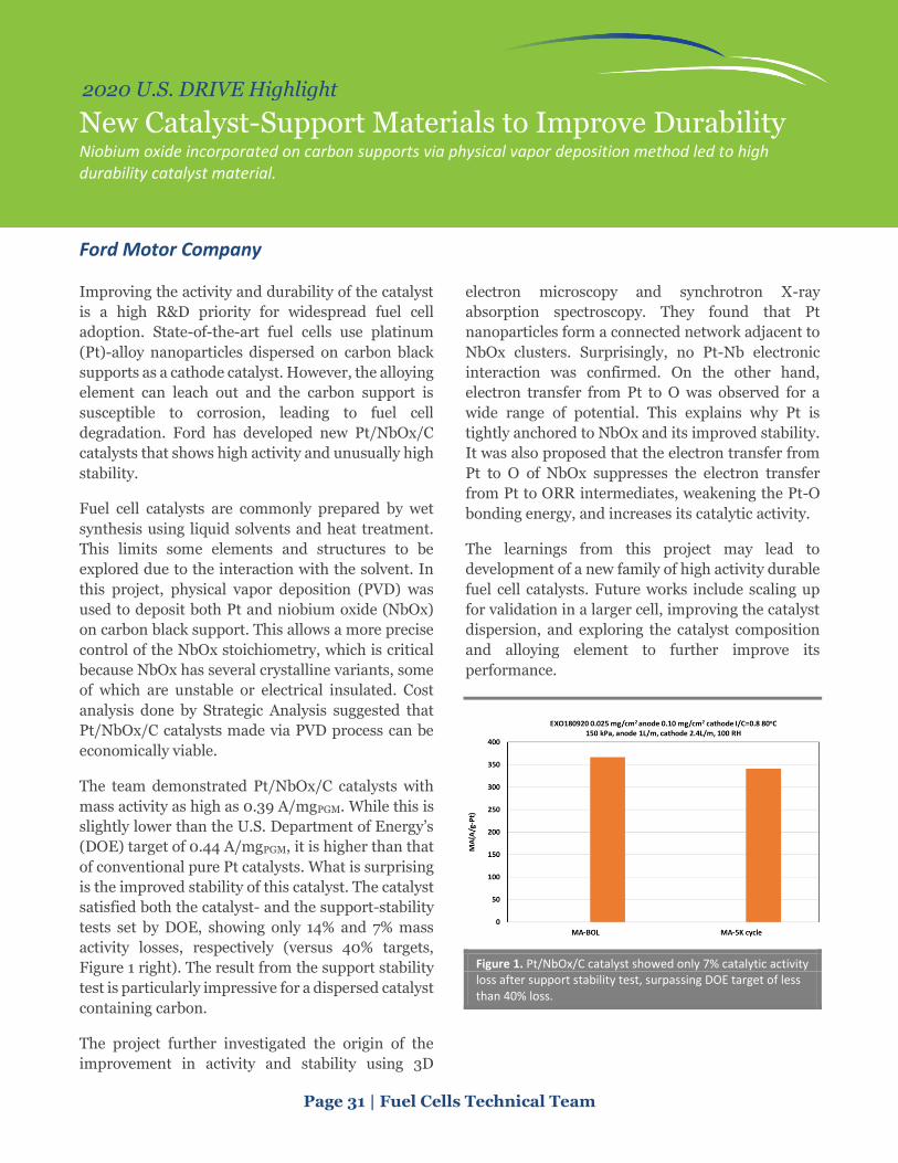
Page 31 | Fuel Cells Technical Team
2020 U.S. DRIVE Highlight
New Catalyst-Support Materials to Improve Durability Niobium oxide incorporated on carbon supports via physical vapor deposition method led to high durability catalyst material.
Ford Motor Company
Improving the activity and durability of the catalyst
is a high R&D priority for widespread fuel cell
adoption. State-of-the-art fuel cells use platinum
(Pt)-alloy nanoparticles dispersed on carbon black
supports as a cathode catalyst. However, the alloying
element can leach out and the carbon support is
susceptible to corrosion, leading to fuel cell
degradation. Ford has developed new Pt/NbOx/C
catalysts that shows high activity and unusually high
stability.
Fuel cell catalysts are commonly prepared by wet
synthesis using liquid solvents and heat treatment.
This limits some elements and structures to be
explored due to the interaction with the solvent. In
this project, physical vapor deposition (PVD) was
used to deposit both Pt and niobium oxide (NbOx)
on carbon black support. This allows a more precise
control of the NbOx stoichiometry, which is critical
because NbOx has several crystalline variants, some
of which are unstable or electrical insulated. Cost
analysis done by Strategic Analysis suggested that
Pt/NbOx/C catalysts made via PVD process can be
economically viable.
The team demonstrated Pt/NbOx/C catalysts with
mass activity as high as 0.39 A/mgPGM. While this is
slightly lower than the U.S. Department of Energy’s
(DOE) target of 0.44 A/mgPGM, it is higher than that
of conventional pure Pt catalysts. What is surprising
is the improved stability of this catalyst. The catalyst
satisfied both the catalyst- and the support-stability
tests set by DOE, showing only 14% and 7% mass
activity losses, respectively (versus 40% targets,
Figure 1 right). The result from the support stability
test is particularly impressive for a dispersed catalyst
containing carbon.
The project further investigated the origin of the
improvement in activity and stability using 3D
electron microscopy and synchrotron X-ray
absorption spectroscopy. They found that Pt
nanoparticles form a connected network adjacent to
NbOx clusters. Surprisingly, no Pt-Nb electronic
interaction was confirmed. On the other hand,
electron transfer from Pt to O was observed for a
wide range of potential. This explains why Pt is
tightly anchored to NbOx and its improved stability.
It was also proposed that the electron transfer from
Pt to O of NbOx suppresses the electron transfer
from Pt to ORR intermediates, weakening the Pt-O
bonding energy, and increases its catalytic activity.
The learnings from this project may lead to
development of a new family of high activity durable
fuel cell catalysts. Future works include scaling up
for validation in a larger cell, improving the catalyst
dispersion, and exploring the catalyst composition
and alloying element to further improve its
performance.
Figure 1. Pt/NbOx/C catalyst showed only 7% catalytic activity loss after support stability test, surpassing DOE target of less than 40% loss.

Page 32 | Fuel Cells Technical Team
2020 U.S. DRIVE Highlight
Operating Conditions to Enhance Membrane Electrode Assembly Durability Identified Knowledge of degradation mechanisms provides additional insight towards meeting durability target.
General Motors
Durability and performance are the major barriers
for automotive fuel cell commercialization. In this
project led by General Motors (GM), the objective
was to enhance the durability of state-of-the-art
membrane electrode assemblies (MEA’s) through
optimization of operating conditions, instead of
material innovation. For electrode durability, the
team pursued a design of experiments to map the
impacts of temperature, relative humidity (RH), and
upper voltage on the degradation behaviors in
voltage cycling. The team developed a statistical
model with predictive equations for electrochemical
active surface and power losses. Furthermore,
Argonne National Laboratory’s (ANL) predictive
model was refined with the voltage cycling data from
this project, and then used to identify the desired
operating conditions that could prolong the
electrode durability to 5000 h and 8000 h in drive
cycles. For membrane durability, the team gained
fundamental knowledge on migration of chemical
stabilizer cerium and synergistic effects of
mechanical and chemical degradations, which is
expected to contribute to the development of a
unified predictive degradation model.
Through the design of experiments, statistical
analysis, and modeling, GM was able to map the
impact of operating conditions and derive a benign
operating window to prolong the lifetime. Figure 1,
one can see different operating windows for RH,
temperature, and upper voltage to retain less than
20% electrochemical area (ECA) loss at end-of-life
(EOL) after 60 K voltage cycles. Together with ANL’s
model, the team was able to demonstrate achieving
5000 h and 8000 h electrode life in drive cycle by
mitigating upper voltage limit, reducing RH, etc.
Comprehensive cerium transport measurement and
modeling has provided insights on the membrane
degradation mechanism, a key trend being cerium
depletion at the cathode outlet where RH cycling is
dominant. Accumulating cerium in the non-active
area has been observed experimentally and captured
by modeling. Furthermore, because both mechanical
and chemical stresses can accelerate membrane
degradation, ex situ experiments were conducted to
understand the interaction between mechanical
stress and fluoride emission rate (FER, an indicator
of chemical degradation), as shown in Figure 2.
Figure 1. Operating window to retain less than 20% ECA loss or 10% voltage loss at EOL, obtained from modeling together with design of experiment data.
Figure 2. Fluoride emission rates under differential pressures.

Page 33 | Fuel Cells Technical Team
2020 U.S. DRIVE Highlight
Ordered Intermetallic Nanoparticle Catalysts Demonstrate High Activity and Improved Durability Ordered-intermetallic catalysts demonstrate improved durability in a membrane electrode assembly while providing the performance benefits of alloys, meeting catalyst activity and durability targets.
Los Alamos National Laboratory
The activity of platinum (Pt) catalysts can be
improved by alloying Pt with other metals. Alloys
with nickel (Ni) or cobalt (Co) show improved
activity and have been developed into commercial
catalysts. However, these alloys tend to have lower
durability than pure Pt catalysts, as the Ni or Co
leach from the alloy catalyst particle during fuel cell
operation. Los Alamos National Laboratory (LANL)
has developed alloy catalysts that maintain high
activity and reduce the dissolution of the non-Pt
metal. The key to the improved durability is
obtaining an ordered structure in the alloy particle,
as illustrated in Figure 1.
Previous work in this project had demonstrated the
durability of these ordered nanoparticle catalysts. In
this past year, LANL has improved their
understanding of how to form the ordered structures
and how the structure improves durability. The
ordered intermetallics have reduced areas of high Co
or Ni content. Density functional theory calculations
indicate these high-Co content areas reduce the
barrier for Co diffusion, making leaching of the Co
easier.
Forming a Pt skin on the surface of the ordered
intermetallic particles further reduces Co leaching.
LANL has investigated the impact of the Pt skin
thickness on both durability and performance. As
shown in Figure 2, the ordered-intermetallic PtCo
with thick Pt shell layers (more than 0.5 nm) had
higher durability and higher end-of-life (EOL)
performance than that with thin Pt shells (less than
0.5 nm), but slightly lower beginning-of-life (BOL)
performance. The thicker Pt shell reduced the
performance loss at 0.8 A/cm2 after cycling from 35
mV for the thin shell catalysts to 19 mV for the thick
shell catalyst, meeting the U.S. Department of
Energy’s (DOE) target (more than 30 mV). LANL has
also investigated the impacts of catalyst particle size
on the activity and durability of these intermetallics.
Decreasing the particle size from 4-5 nm to 3-4 nm
increased catalyst mass activity but resulted in
reduced durability. The literature indicates smaller
PtCo particles have poor ordering. LANL has
discovered that adding zinc to form a ternary system
improves ordering, which may lead to smaller, more
active durable catalysts in the future.
Figure 1. STEM micrograph of an ordered intermetallic PtCo particle with a 0.45 nm Pt shell.
Figure 2. LANL has deposited the binary PtCo catalysts on carbon supports and integrated these catalysts into membrane electrode assemblies that meet DOE targets for mass activity (>0.44 A/mg PGM), catalyst durability (40% loss in mass activity, 30 mV loss in performance at 0.8 A/cm2), and performance (>1 W/cm2).

Page 34 | Fuel Cells Technical Team
2020 U.S. DRIVE Highlight
Fuel Cell Modeling and Cost Analysis Highlight Research Opportunities for Heavy-Duty Vehicles Detailed cost models provide documented public reference for annual assessment of progress towards the U.S. Department of Energy’s Hydrogen and Fuel Cell Technologies Office goals.
Strategic Analysis Incorporated
Fuel cell cost analysis is critical for demonstrating
the significant progress that has been made through
research and development activities and in
identifying potential areas of R&D focus for cost
reduction. It also provides the fuel cell community
with a referenceable standard widely utilized in
further analyses. In the past year, Strategic Analysis,
Inc. (SA) applied their fuel cell system cost analyses
to medium-duty and heavy-duty (MD/HD) vehicle
applications, which are rapidly becoming the
primary application focus of numerous fuel cell
developers and original equipment manufacturers.
This study has independently estimated the cost of
2025 HD vehicle fuel cell systems at high volume
production (100,000 units/yr) at $112/kW, with the
U.S. Department of Energy’s (DOE) ultimate target
set at $60/kW. A total cost of ownership (TCO) study
of Class 8 long-haul fuel cell truck suggested a
~$1.58/mi cost, ~25% higher than benchmark
diesel, while providing a green solution.
SA developed their realistic automotive fuel cell
power plant system cost model in collaboration with
detailed performance and durability fuel cell
modeling from Argonne National Laboratory (ANL),
continually updated balance-of-plant data and
feedback from component developers, and recent
results from DOE Hydrogen and Fuel Cell
Technologies Office projects. SA derives their own
manufacturing process assumptions based on
Design for Manufacture and Assembly techniques,
and validates their assumptions with extensive
industry interaction, peer review, and U.S. DRIVE
Fuel Cell Technical Team Reviews.
SA applied their cost modeling analysis to identify
low cost solutions applicable to the specific
requirements of MD/HD applications (primarily
greater durability and lifetime). The team performed
a comprehensive review of durability-enhancing
options and assessed cost impact. Results assist the
DOE and community in driving R&D targets such as
ranges for recommended precious metal catalyst
loadings (higher than light-duty vehicles [LDV]),
operating temperature (below LDV for enhanced
durability), cell voltage optimization, fuel cell stack
power density, and FC/battery hybridization. This
analysis provides insights that will help guide the
direction of the new Million Mile Fuel Cell Truck
(M2FCT) consortium.
The team performed a detailed TCO study for a Class
8 long-haul HD fuel cell application, finding that the
TCO is most sensitive to truck ownership life and
fuel cost. System efficiency has also been identified
as a significant driver of overall cost. Such a model
can be exercised in future studies to further optimize
fuel cell design and operation for the more relevant
TCO rather than just initial system cost. Studies may
include refinement of target durability enabler
assessments, maximum operating temperature, and
catalyst loadings.
Figure 1. Class 8 long-haul truck total cost of ownership tornado chart shows hydrogen cost and truck life (durability) as key drivers.

Materials

Page 36 | Materials Technical Team
2020 U.S. DRIVE Highlight
Corrosion Protection of Dissimilar Material and Joining for Next-Generation Lightweight Vehicles Evaluation of corrosion behavior of a multi-material joining technology that leverages the existing resistance spot welding automotive infrastructure.
Arconic Technology Center
The Arconic Technology Center is working with
Honda R&D Americas, LLC and the Ohio State
University (OSU) to evaluate the corrosion
performance and demonstrate the production
worthiness of the Resistance Spot Riveting (RSR™)
process. RSR is a new technology being developed by
Howmet Fastening Systems (formerly Arconic, Inc.)
that employs a fastener that is installed using
conventional resistance spot welding equipment to
produce multi-material joints.
The goal of the 3-year project is to demonstrate the
use of RSR to join aluminum (Al) to steel and Al to
carbon fiber composites on a prototype scale.
Deployment of this technology would help the
automotive industry achieve an additional 10%-20%
weight reduction over high strength steels. These
weight-savings to the body in white generally
translates to 2.5%-5% of overall vehicle curb weight.
The resulting total weight-savings could provide a
1.5% to 3% total improvement in fuel efficiency for
vehicles that incorporate RSR for multi-material
joining.
The RSR technology addresses several production
barriers to achieving the U.S. Department of
Energy’s fuel efficiency targets including eliminating
the need of additional capital for new joining
technologies, and the flexibility to process
conventional steel and multi-material structures
with the same equipment. Additionally, the trend
towards ultra-high strength steels limits the
availability of conventional joining technologies that
can effectively process these multi-material
combinations. In order to accomplish these goals,
the following program milestones were developed by
the team:
• Develop RSR process parameters, producing multi-material joints for mechanical testing and corrosion assessments.
• Conduct corrosion evaluation and choose a corrosion mitigation strategy.
• Develop a production ready feed system and mount to a robotic system to simulate production conditions.
• Produce demonstration assemblies for testing
and evaluation.
The fourth year of this project focused on completing
the corrosion studies at OSU and Honda. The last
program milestone, fabrication and testing of the
demonstration articles, is targeted for completion in
early 2021. Fabrication using the RSR robotic
assembly cell was planned in two steps. Initial
assemblies would be used to establish the design and
verify the mechanical performance against Honda’s
predicted simulations. Changes would then be
incorporated into the final demonstration pieces
targeted to be tested by testing at Honda in January
2021. A photo of the initial demonstrator is shown in
Figure 1.
Figure 1. Assembled demonstrator prior to mechanical testing. Source: Honda
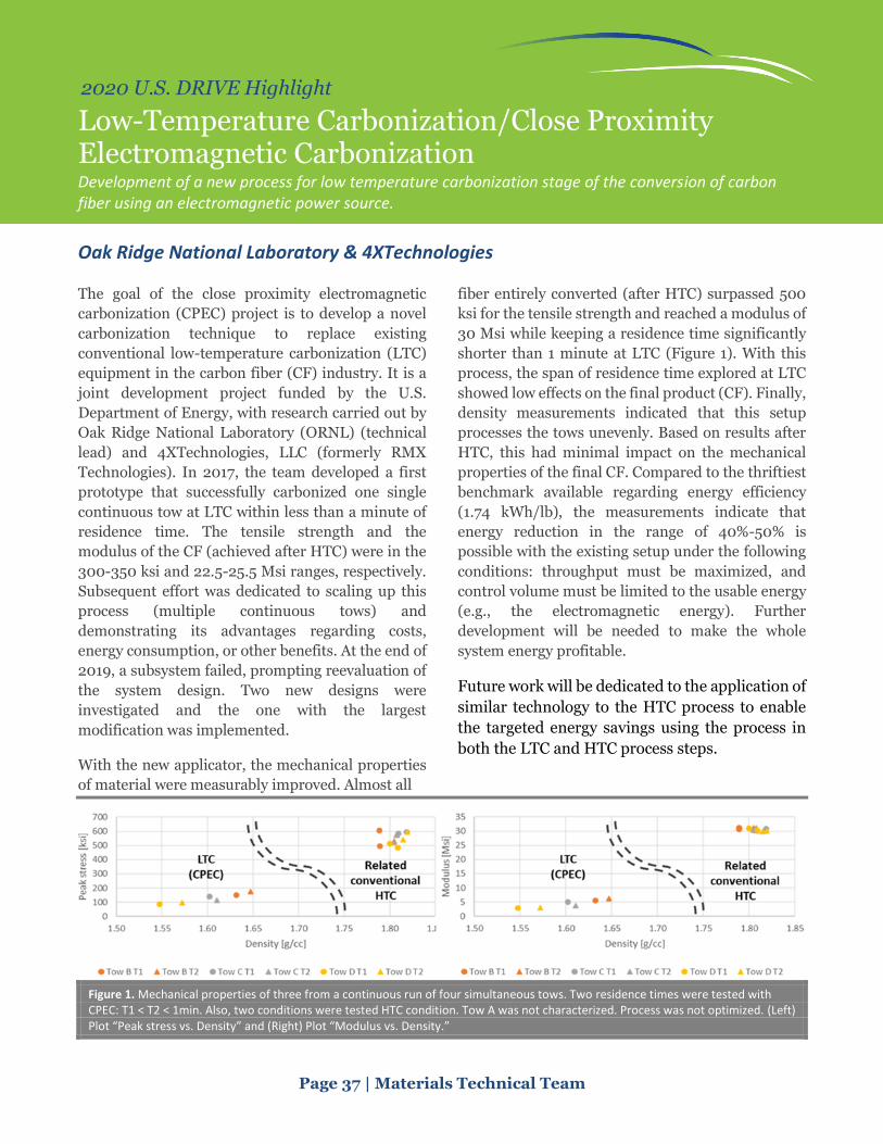
Page 37 | Materials Technical Team
2020 U.S. DRIVE Highlight
Low-Temperature Carbonization/Close Proximity Electromagnetic Carbonization Development of a new process for low temperature carbonization stage of the conversion of carbon fiber using an electromagnetic power source.
Oak Ridge National Laboratory & 4XTechnologies
The goal of the close proximity electromagnetic
carbonization (CPEC) project is to develop a novel
carbonization technique to replace existing
conventional low-temperature carbonization (LTC)
equipment in the carbon fiber (CF) industry. It is a
joint development project funded by the U.S.
Department of Energy, with research carried out by
Oak Ridge National Laboratory (ORNL) (technical
lead) and 4XTechnologies, LLC (formerly RMX
Technologies). In 2017, the team developed a first
prototype that successfully carbonized one single
continuous tow at LTC within less than a minute of
residence time. The tensile strength and the
modulus of the CF (achieved after HTC) were in the
300-350 ksi and 22.5-25.5 Msi ranges, respectively.
Subsequent effort was dedicated to scaling up this
process (multiple continuous tows) and
demonstrating its advantages regarding costs,
energy consumption, or other benefits. At the end of
2019, a subsystem failed, prompting reevaluation of
the system design. Two new designs were
investigated and the one with the largest
modification was implemented.
With the new applicator, the mechanical properties
of material were measurably improved. Almost all
fiber entirely converted (after HTC) surpassed 500
ksi for the tensile strength and reached a modulus of
30 Msi while keeping a residence time significantly
shorter than 1 minute at LTC (Figure 1). With this
process, the span of residence time explored at LTC
showed low effects on the final product (CF). Finally,
density measurements indicated that this setup
processes the tows unevenly. Based on results after
HTC, this had minimal impact on the mechanical
properties of the final CF. Compared to the thriftiest
benchmark available regarding energy efficiency
(1.74 kWh/lb), the measurements indicate that
energy reduction in the range of 40%-50% is
possible with the existing setup under the following
conditions: throughput must be maximized, and
control volume must be limited to the usable energy
(e.g., the electromagnetic energy). Further
development will be needed to make the whole
system energy profitable.
Future work will be dedicated to the application of
similar technology to the HTC process to enable
the targeted energy savings using the process in
both the LTC and HTC process steps.
Figure 1. Mechanical properties of three from a continuous run of four simultaneous tows. Two residence times were tested with CPEC: T1 < T2 < 1min. Also, two conditions were tested HTC condition. Tow A was not characterized. Process was not optimized. (Left) Plot “Peak stress vs. Density” and (Right) Plot “Modulus vs. Density.”
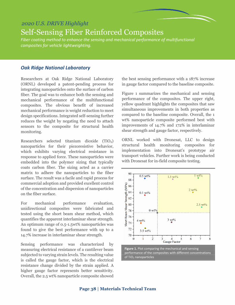
Page 38 | Materials Technical Team
2020 U.S. DRIVE Highlight
Self-Sensing Fiber Reinforced Composites Fiber coating method to enhance the sensing and mechanical performance of multifunctional composites for vehicle lightweighting.
Oak Ridge National Laboratory
Researchers at Oak Ridge National Laboratory
(ORNL) developed a patent-pending process for
integrating nanoparticles onto the surface of carbon
fiber. The goal was to enhance both the sensing and
mechanical performance of the multifunctional
composites. The obvious benefit of increased
mechanical performance is weight reduction to meet
design specifications. Integrated self-sensing further
reduces the weight by negating the need to attach
sensors to the composite for structural health
monitoring.
Researchers selected titanium dioxide (TiO2)
nanoparticles for their piezoresistive behavior,
which exhibits varying electrical resistance in
response to applied force. These nanoparticles were
embedded into the polymer sizing that typically
coats carbon fiber. The sizing acted as a carrier
matrix to adhere the nanoparticles to the fiber
surface. The result was a facile and rapid process for
commercial adoption and provided excellent control
of the concentration and dispersion of nanoparticles
on the fiber surface.
For mechanical performance evaluation,
unidirectional composites were fabricated and
tested using the short beam shear method, which
quantifies the apparent interlaminar shear strength.
An optimum range of 0.5-1.5wt% nanoparticles was
found to give the best performance with up to a
14.7% increase in interlaminar shear strength.
Sensing performance was characterized by
measuring electrical resistance of a cantilever beam
subjected to varying strain levels. The resulting value
is called the gauge factor, which is the electrical
resistance change divided by the strain applied. A
higher gauge factor represents better sensitivity.
Overall, the 2.5 wt% nanoparticle composite showed
the best sensing performance with a 187% increase
in gauge factor compared to the baseline composite.
Figure 1 summarizes the mechanical and sensing
performance of the composites. The upper right,
yellow quadrant highlights the composites that saw
simultaneous improvements in both properties as
compared to the baseline composite. Overall, the 1
wt% nanoparticle composite performed best with
improvements of 14.7% and 172% in interlaminar
shear strength and gauge factor, respectively.
ORNL worked with Dronesat, LLC to design
structural health monitoring composites for
implementation into Dronesat’s prototype air
transport vehicles. Further work is being conducted
with Dronesat for in-field composite testing.
Figure 1. Plot comparing the mechanical and sensing performance of the composites with different concentrations of TiO2 nanoparticles

Page 39 | Materials Technical Team
2020 U.S. DRIVE Highlight
Ultrasonic Spot Welding of Magnesium to High-Strength Steel Sheets A solid-state joining technology to join lightweight dissimilar materials that are unweldable by conventional fusion welding methods.
Oak Ridge National Laboratory
With increasing demand of lightweight materials in
automobiles to reduce fuel consumption and
greenhouse gas emissions, magnesium (Mg) alloys
have received much attention due to their low
density and high specific strength. However, joining
Mg alloys with steel structures is challenging. This is
because the physical and chemical properties of
these two materials are very different. The melting
point of Mg is 650°C versus steel or iron (Fe) at
approximately 1500°C. Mg and Fe are immiscible
and no intermetallic compounds are formed in the
Mg/Fe system. The solubility between them is very
low. Thus, although bonding of coated steel with Mg
alloy have been possible via brazing, Mg to uncoated
steel is considered unweldable by conventional
fusion welding methods.
Ultrasonic spot welding (USW) technology provides
a potential option to overcome the technical barriers
preventing robust and reliable joining of Mg to steel.
During USW processes, the ultrasonic transducer
delivers a moderate clamping force and a high-
frequency interfacial vibration into the joint
interface. The welding heat is mainly generated
through interfacial friction, but the temperature rise
is generally not sufficient to melt the materials.
Instead, the high temperature and pressure at the
interface induce a rapid diffusion between the
substrates to form the joint.
Figure 1(a) shows the cross-section of a USW joint
made with uncoated DP590 steel and AZ31B Mg
alloy (3% aluminum [Al]). Figure 1(b) presents the
chemical analysis across the joint interface in the
center region. The high concentration of Al at the
joint interface suggests the presence of Al-Fe
intermetallic compounds that is critical to joint
formation. Lap shear tensile testing in Figure 2
shows a peak load of approximately 5 kN achieved.
This research demonstrated the feasibility and
obtains the fundamental understanding of the
weldability of USW method for joining Mg-steel
dissimilar metal pairs. Next steps will focus on
evaluating the structural responses during the USW
process and its influence on fabrication of
component level structures.
Figure 1. (a) Cross-section of a Mg-steel USW joint, (b) element distributions across the joint interface.
Figure 2. Lap shear coupons and lap shear tensile load versus extension curves.

Page 40 | Materials Technical Team
2020 U.S. DRIVE Highlight
Low-Cost Aluminum and Magnesium Extrusions Development of Shear-Assisted Processing and Extrusion to achieve improved mechanical properties using a lower cost feedstock material.
Pacific Northwest National Laboratory and Magna Collaboration
As aluminum and eventually magnesium extrusions
begin to displace steel for fabricating automotive
components, the impact towards lightweighting can
range from a 25% to 45% weight reduction, thereby
enabling greater vehicle fuel efficiency. However,
this potential weight savings comes at a price and
new processing methods are needed to minimize
that cost. To this end, Pacific Northwest National
Laboratory (PNNL) and Tier 1 supplier Magna
International are co-developing Shear-Assisted
Processing and Extrusion (ShAPE™) to lower the
cost of aluminum and magnesium extrusions.
ShAPE is an emerging extrusion technology where
feedstock material is translated into a rotating die,
resulting in heat generation due to friction and
severe deformation of the material. The heat helps to
reduce the forces required for extruding the material
and also reduces energy requirements. The
combined effect of axial force and rotational shear
promotes refinement of the metal grain structure
and achieves better uniformity. These novel metal
structures enabled by ShAPE led to improvements in
material performance that result in more effective
use of lightweight metals at a cost savings.
For this project, AA6063 tubing with a 12 mm
diameter and 1–2 mm wall thickness (see Figure 1)
was extruded at rates that are competitive with
current commercial manufacturing. In other
instances, ShAPE has achieved manufacturing rates
over 5x that achievable by other processes. With
ShAPE, the energy and cost associated with
preparing the billet for extrusion and pre-heating are
eliminated, and the ability to use a high percentage
of secondary aluminum further reduces embedded
energy and cost. The as-extruded aluminum tube
responded well to aging; it had a T5 temper
exceeding the ASTM standard tensile strength for
the higher T6 temper, thus avoiding the cost and
energy associated with post-extrusion T6 solution
heat treatment and quenching steps. This represents
a potential for significant overall cost and energy
reduction for aluminum extrusion.
AA6063 UTS (MPa) YS
(MPa) Elongation (%)
ShAPE™ (T5) 233 198 11
ASTM 02.02 (T6) 205 170 8
For magnesium alloys, the ShAPE process enables
control of crystallographic alignment, which has
been shown to virtually eliminate anisotropy,
thereby bringing energy absorption of non-rare-
earth ZK60-T5 on par with AA6061-T6. This project
is now moving toward non-circular profiles with the
goal of manufacturing multi-wall extrusions that
have non-circular profiles.
The current research activity is associated with a
Cooperative Research and Development Agreement
through the LightMAT consortium, funded by the
U.S. Department of Energy’s Vehicle Technologies
Office. In 2019, Magna executed a research license
and option agreement, associated with the
intellectual property developed by PNNL for specific
fields of use. In October 2020, PNNL researchers
were awarded an R&D100 award for ShAPE.
Figure 1. Cross section of the ShAPE™ tooling/process (left). AA6063 tubing with a 12 mm diameter and 1–2 mm wall thickness (right).

Page 41 | Materials Technical Team
2020 U.S. DRIVE Highlight
Low-Cost Corrosion Protection for Magnesium Development of a non-coating-based surface modification technique for corrosion protection in magnesium alloy sheet metal.
Pacific Northwest National Laboratory
Magnesium (Mg) is 30% less dense than aluminum
(Al) but unlike Al alloys, Mg alloys have poor
corrosion resistance, especially in chloride-
containing environments such as those encountered
in winter driving on salted roads. Because Mg is
highly anodic, dissimilar Mg-based joints are
susceptible to galvanic corrosion. Magnesium is one
of the most promising lightweighting materials for
applications in a car body and chassis, according to
the U.S. Department of Energy and its partners in
the automotive industry. Hence, the development of
cost-effective and durable protective coatings has
been identified as an important research need to
help meet vehicle efficiency targets for future
vehicles.
Pacific Northwest National Laboratory (PNNL)
researchers are working to develop low-cost
techniques to protect Mg from corrosion. Although
commercial corrosion protection methods exist, they
are generally expensive and involve the use of
multiple chemical baths that may also have serious
environmental impacts. As a result, the use of Mg
sheet metal in high-volume automotive applications
is still limited, and the development of corrosion
protection techniques is an active area of research.
To address these challenges, the team is focused on:
• Using laser surface processing (LSP) to locally modify the surface microstructure of AZ31B Mg alloy sheet metal for greater corrosion resistance relative to unprocessed sheet.
• Conducting electrochemical testing using ASTM B117 and advanced analytical techniques to correlate LSP Mg sheet corrosion behavior to its microstructure features.
• Exploring alternate techniques for producing coatings for corrosion protection without the use of harsh chemicals.
Initial ASTM B117 test results show promising
corrosion protection effects of LSP on AZ31B; an
order of magnitude lower corrosion product is
formed relative to unprocessed sheet. Subsequent
electrochemical testing also shows improved
protection capability that confirms the performance
of the LSP technique. By examining LSP samples via
electron microscopy and other advanced techniques,
PNNL researchers observed an outer ~0.5 m thick
mixed-metal (Mg, Al) oxide-hydroxide layer atop a
dense, ~20 nm thick Al-rich oxide layer Figure 1). In
addition, Al-Mn intermetallic particles seemed to be
refined in the near-surface region as well. The
combination of these features is believed to create a
protective barrier and reduce the tendency for
localized micro-galvanic corrosion effects, all of
which result in greater corrosion resistance. The
team is now exploring the potential of hydro-thermal
techniques to create corrosion protection coatings.
If successful, this research will lead to lower-cost and
chemically benign methods for corrosion protection
of automotive Mg alloys.
Figure. 1. A high-magnification electron-microscopy image of the surface film in a LSP Mg AZ31B sheet sample.

Page 42 | Materials Technical Team
2020 U.S. DRIVE Highlight
Room-Temperature Stamping of High-Strength Aluminum Alloys Novel processing approaches enable lightweight structural components made of high-strength aluminum alloys.
Pacific Northwest National Laboratory
Researchers at Pacific Northwest National
Laboratory are working to overcome challenges
related to stamping high-strength aluminum (Al)
sheets at room temperature to form them into highly
complex automotive structural components. Based
on discussions with original equipment
manufacturers and Tier-I industry partners, the
team selected a door side-impact beam currently
fabricated in steel as a demonstration component
that, if stamped out of high-strength AA7075 Al
alloy, would help meet the U.S. Department of
Energy’s (DOE’s) targets for 2025: A 25% glider
mass reduction relative to a comparable vehicle
manufactured in 2012, and a cost penalty of no more
than $5 per pound of weight saved.
Two significant manufacturing challenges are to
stamp the beam at room temperature (i.e., both the
sheet and the dies) without cracking, and once
stamped, confirm the beam does not require
artificial aging to strengthen it. These two challenges
exist because alternate approaches, such as hot-
stamping (to achieve the beam shape) and artificial
aging (to strengthen the beam), are not cost-effective
for the high-volume automotive industry. These
challenges are addressed by developing a
fundamental understanding of precipitation
hardening kinetics. The models produced indicated
the existence of more formable tempers of AA7075.
The benefit of this approach has been demonstrated
on commercially acquired and stamped sheet metal.
The stamped AA7075 beam (Figure 1) is
approximately 38% lighter, looks identical to the
baseline steel beam, and has the same dimensional
tolerance. Visual examination of the Al beam does
not reveal any apparent surface defects, necks, or
cracks to the naked eye, indicating that the first
challenge of formability has been met.
The macro-hardness was mapped across the as-
stamped Al at multiple locations. Overall, about 250
hardness measurements were made of multiple
beams and the average hardness was >90% of the
ASTM T6 temper specification. Small-sized tensile
test coupons were cut from the flat sections of the
beam, and initial stress-strain data suggested they
had a strength similar to the T6 temper strength,
showing near-peak strength was achieved in the
stamped beam without artificial aging, indicating
that the second challenge has also been met.
This work has successfully developed and
demonstrated an approach to stamping structural
components out of a high-strength Al alloy at room
temperature. We expect this approach to be more
cost-effective than hot-stamping and artificial aging
of high-strength Al. If this approach is extended to
other structural components to replace steel with
high-strength Al, it could help the automotive
industry achieve the DOE’s lightweighting and cost
targets.
Figure 1. A side-by-side comparison of the production steel side-impact beam and the prototype high-strength Al beam.

Page 43 | Materials Technical Team
2020 U.S. DRIVE Highlight
Predictive Tools Development for Low-Cost Carbon Fiber for Lightweight Vehicles Development of a computational framework for carbon fiber synthesis and experimental demonstration of carbon fiber synthesis from low-cost precursors.
University of Virginia, Pennsylvania State University, Oak Ridge National Laboratory,
Solvay Composites (Cytec Materials), Oshkosh Corporation
Carbon fiber reinforced polymers are stronger and
lighter than engineering-grade metal alloys, so
employing them in automotive structures can greatly
reduce vehicle mass, thereby increasing fuel
efficiency. However, their widespread adoption has
been hindered by the high cost of carbon fibers
(CFs). CFs are produced by thermochemically
converting a polymeric fiber, called a precursor, into
a fiber of carbon. This precursor accounts for over
half of the final cost of a CF. Therefore, this project
focused on the development of low-cost alternative
CF precursors and pursued optimization of the
processing techniques for CF conversion.
The team developed and utilized an integrated
computational materials engineering (ICME)
framework to identify alternative CF precursors
(Figure 1). Under this ICME framework, precursor
candidates were analyzed with ReaxFF molecular
dynamics simulations to elucidate the underlying
chemical reactions driving the conversion of the
material across the different stages of
manufacturing. The chemical structure identified via
ReaxFF was then assembled into polymer ladders
and built into large-scale representations of fibers.
Large-scale molecular dynamics simulations were
thus capable of applying loading conditions to
characterize the microstructure/property
relationships of the CF. The team performed
experimental characterization, including single
filament tensile testing, electron microscopy, and
thermogravimetric analysis, to validate the
simulation predictions. This ICME framework thus
formed a closed-loop system of simulation and
experimental validation to evaluate multiple
alternative precursors to downselect candidate
precursors.
The team used key insights from multiscale
molecular dynamics simulations to further enhance
CF conversion techniques. Simulations unveiled the
role that microstructures and molecular
configuration changes play in CF mechanical
properties. These newly uncovered microstructure-
property relationships assisted the team in
optimizing the conversion of multiple alternative CF
precursors. New characterization techniques were
also demonstrated, including novel fiber
microstructure mapping with various microscopies.
Through this ICME framework, the team
demonstrated low-cost carbon fibers exceeding the
U.S. DRIVE targets.
Figure 1. A graphical representation of the ICME project strategy, leveraging ReaxFF simulations to uncover the conversion of precursor materials, large-scale molecular dynamics simulations to reveal microstructural characteristics, and experimental validation of the fiber properties.

INFRASTRUCTURE AND INTEGRATION
Grid Integration

Page 45 Grid Integration Technical Team
2020 U.S. DRIVE Highlight
Grid Impacts of Electric Vehicle Charging at Scale are Mitigated with Smart Charge Management Solutions Analysis of electric vehicle adoption suggests certain charging preferences could result in significant impacts to electric utility equipment that can be mitigated with smart charge controls.
National Renewable Energy Laboratory
The increasing adoption of electric vehicles (EVs)
will result in significant electrical load growth in the
coming decade. Driving patterns show that a
vehicle’s typical dwell period while parked exceeds
the time required to recharge most vehicle batteries.
This charging flexibility creates an opportunity to
distribute charging load to facilitate a higher
adoption of EVs and intermittent renewable
resources. High coincident charging peaks could
exceed electrical equipment capacity, resulting in the
need for expensive upgrades.
The National Renewable Energy Laboratory, Sandia
National Laboratories, and Idaho National
Laboratory have developed models for EV load
growth in Atlanta and Minneapolis. The models
incorporate vehicle travel patterns, light-duty EV
adoption rates, and charging preferences to assess
overall energy needs. Figure 1 displays a 24-hour
load profile for a primarily commercial feeder in
Atlanta during a summer peak day with a regional
clustering of EV adoption at 30%.
Figure 1. The EV home-dominant case increases peak load by 500 kW, whereas the work-dominant case increases energy and power needs, while shifting the peak 8 hours earlier. These differences are due to workplace charging drawing in more commercial load from nearby residential feeders.
Although charging and infrastructure preferences
can shift EV profiles, a more direct approach is
needed to mitigate grid impacts. The project team
developed smart charge controls to mitigate impacts
such as an overloaded primary circuit by shifting EV
charging load within a vehicle’s dwell period. The
centralized control schedules EV charging to reduce
the feeder peak, while another schedules a random
distribution. They are compared to strategies that
mimic adherence to time-of-use (TOU) rates which
incentivize charging within low-cost windows as
shown through either immediate or randomized
start-time controls. Figure 2 displays the 24-hour EV
load for a Minneapolis feeder.
Figure 2. The immediate control highlights a potential timer peak risk in EV load at 9:00 PM. The central control reduces feeder peak and shifts charging to increase load factor, while both of the random controls create a more even distribution.
The average peak line loading increased by 6% in
the uncontrolled case, while centralized and
random controls only saw a 3% increase. In
contrast, immediate control implementation to
follow TOU rates could represent as much as a
30% increase. This study shows how proper
smart charge controls will help to facilitate the
increasing adoption of EVs.

Hydrogen Codes and Standards
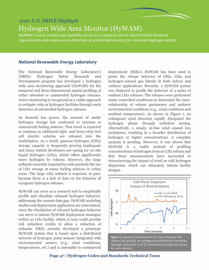
Page 47 | Hydrogen Codes and Standards Technical Team
2020 U.S. DRIVE Highlight
Hydrogen Wide Area Monitor (HyWAM) HyWAM’s active monitoring capability serves as a research tool to inform facility footprint requirements and enables early detection of unintended releases for improved hydrogen safety.
National Renewable Energy Laboratory
The National Renewable Energy Laboratory’s
(NREL) Hydrogen Safety Research and
Development program has developed a hydrogen
wide area monitoring approach (HyWAM) for the
temporal and three-dimensional spatial profiling of
either intended or unintended hydrogen releases.
Active monitoring is recognized as a viable approach
to mitigate risks at hydrogen facilities through early
detection of unintended hydrogen releases.
As demand has grown, the amount of onsite
hydrogen storage has continued to increase at
commercial fueling stations. That trend is expected
to continue as additional light- and heavy-duty fuel
cell electric vehicles are released into the
marketplace. As a result, gaseous hydrogen (GH2)
storage capacity is frequently proving inadequate
and many station developers are opting for on-site
liquid hydrogen (LH2), which offers significantly
more hydrogen by volume. However, the large
setbacks currently required by code preclude the use
of LH2 storage at many fueling stations in urban
areas. The large LH2 setback is required, in part,
because there is a lack of data on the behavior of
cryogenic hydrogen releases.
HyWAM can serve as a research tool to empirically
profile and elucidate released hydrogen behavior,
addressing the current data gap. HyWAM modeling
studies and deployment application are interrelated,
since the elucidation of released hydrogen behavior
can serve to inform HyWAM deployment strategies
within an LH2 facility, which in turn could provide
risk reduction credits to allow a reduction of
setbacks. NREL recently developed a prototype
HyWAM system that is based upon a distributed
network of hydrogen point sensors integrated with
environmental sensors (e.g., wind conditions,
temperatures, etc.) and is amenable to commercial
deployment. NREL’s HyWAM has been used to
probe the release behavior of GH2, LH2, and
hydrogen-natural gas blends in both indoor and
outdoor applications. Recently, a HyWAM system
was deployed to profile the behavior of a series of
outdoor LH2 releases. The releases were performed
under controlled conditions to determine the inter-
relationship of release parameters and ambient
environmental conditions (e.g., wind conditions and
ambient temperature). As shown in Figure 1, an
orthogonal wind direction rapidly dissipated the
hydrogen plume through turbulent mixing.
Alternatively, a steady, in-line wind caused less
turbulence, resulting in a broader distribution of
hydrogen at higher concentrations. A complete
analysis is pending. However, it was shown that
HyWAM is a viable method of profiling
concentrations of hydrogen from an LH2 release and
that these measurements have succeeded in
characterizing the impact of wind on cold hydrogen
dispersion, which can ultimately inform facility
designs.
Figure 1. Impact of wind direction for two horizontal LH2 releases (R1 and R2). An orthogonal wind direction facilitates hydrogen dispersion (1 of 32 measurement points are shown for each release).

Hydrogen Delivery and Storage

Page 49 | Hydrogen Delivery and Storage Technical Team
2020 U.S. DRIVE Highlight
H2FillS: “Hydrogen Filling Simulation” Model to Enable Innovation in Fueling Processes A publicly available model that simulates gas flow from the hydrogen station to the vehicle storage system, designed to model changes in hydrogen temperature, pressure, and mass flow during filling.
National Renewable Energy Laboratory, Kyushu University, Frontier Energy, and 10
collaborators
A team led by the National Renewable Energy
Laboratory (NREL) developed the publicly available
software model H2FillS, which can be used to enable
changes in hydrogen dispensing methods that lower
the cost of fuel. Today, light-duty fuel cell electric
vehicles (FCEVs) store approximately 5 kg of
hydrogen onboard and are filled in 3-5 minutes
using the SAE J2601 fueling protocol. These
characteristics require fueling at low temperatures (-
40°C) and high pressure (875 bar), necessitating the
use of specialized, costly hydrogen fueling station
components, thereby making station cost (currently)
the largest contributor to the cost of dispensed
hydrogen fuel. H2FillS can enable innovations in
fueling methods by allowing a user to characterize
the impact of changes in fuel temperature on the fill
rate and the temperature inside a FCEV’s hydrogen
tank.
H2FillS is based on a 1-dimensional model that
NREL licensed from Kyushu University, validated by
using 21 vehicle tank temperature data sets, and
expanded with an easy-to-use graphical user
interface (GUI) (Figure 1). To validate the model,
data sets from experiments conducted previously
were obtained from NREL, Honda Motor Company,
and PowerTech Labs Inc. Upon validation, the
model was shown to predict the temperature and
pressure of hydrogen inside an FCEV tank within +
3.5 K/MPa of experimental results.
NREL is now expanding the H2FillS software to
enable 3-dimensional modeling of fueling heavy-
duty (HD) FCEVs as part of the Innovating
Hydrogen Stations (IHS) project. The model
developed under IHS could ultimately inform the
development of an HD FCEV fueling protocol. HD
FCEVs are expected to store up to 16X more
hydrogen onboard than light-duty vehicles and
require fueling at rates of over 10 kg/min—5X faster
than fueling rates for light-duty FCEVs. Fill
protocols for HD FCEVs are currently under
development and will be used to inform the design
requirements for stations and storage onboard
vehicles.
H2FillS was co-funded by the U.S. Department of
Energy’s Hydrogen and Fuel Cell Technologies
Office (HFTO) within the Office of Energy Efficiency
and Renewable Energy, along with a large
stakeholder base that informed model development,
to ensure relevance to industry. Stakeholders
included Frontier Energy Inc., Ford Motor
Company, General Motors LLC, Honda R&D
Americas, Hyundai-Kia America Technical Center,
Ivys Energy Solutions Inc., Shell, and Toyota.
Additional project partners, collaborators, and
technical advisors included staff from Kyushu
University, Saga University, Zero Carbon Energy
Solutions, Sandia National Laboratories, and
Argonne National Laboratory. The IHS project is co-
funded by HFTO, Shell, Air Liquide, Toyota, and
Honda.
Figure 1. The H2FillS GUI is easy to use to simulate the thermodynamics of hydrogen fueling.
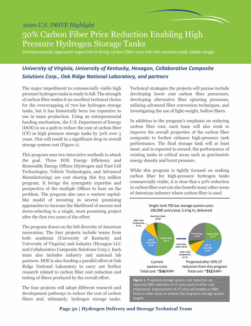
Page 50 | Hydrogen Delivery and Storage Technical Team
2020 U.S. DRIVE Highlight
50% Carbon Fiber Price Reduction Enabling High Pressure Hydrogen Storage Tanks Entrepreneurial approach expected to bring carbon fiber cost into the commercially viable range.
University of Virginia, University of Kentucky, Hexagon, Collaborative Composite
Solutions Corp., Oak Ridge National Laboratory, and partners
The major impediment to commercially viable high
pressure hydrogen tanks is ready to fall. The strength
of carbon fiber makes it an excellent technical choice
for the overwrapping of 700 bar hydrogen storage
tanks, but it has historically been too expensive to
use in mass production. Using an entrepreneurial
funding mechanism, the U.S. Department of Energy
(DOE) is on a path to reduce the cost of carbon fiber
(CF) in high pressure storage tanks by 50% over 5
years. This will result in a significant drop in overall
storage system cost (Figure 1).
This program uses two innovative methods to attack
the goal. Three DOE Energy Efficiency and
Renewable Energy Offices (Hydrogen and Fuel Cell
Technologies, Vehicle Technologies, and Advanced
Manufacturing) are cost sharing this $15 million
program. It brings the synergistic expertise and
perspective of the multiple Offices to bear on the
problem. The program also uses a venture capital-
like model of investing in several promising
approaches to increase the likelihood of success and
down-selecting to a single, most promising project
after the first two years of the effort.
The program draws on the full diversity of American
innovation. The four projects include teams from
both academia (University of Kentucky and
University of Virginia) and industry (Hexagon LLC
and Collaborative Composite Solutions Corp.). Each
team also includes industry and national lab
partners. DOE is also funding a parallel effort at Oak
Ridge National Laboratory to carry out further
research related to carbon fiber cost reduction and
testing of fibers produced by the overall effort.
The four projects will adopt different research and
development pathways to reduce the cost of carbon
fibers and, ultimately, hydrogen storage tanks.
Technical strategies the projects will pursue include
developing lower cost carbon fiber precursors,
developing alternative fiber spinning processes,
utilizing advanced fiber conversion techniques, and
investigating the use of light-weight, hollow fibers.
In addition to the program’s emphasis on reducing
carbon fiber cost, each team will also work to
improve the overall properties of the carbon fiber
composite to further enhance high-pressure tank
performance. The final storage tank will at least
meet, and is expected to exceed, the performance of
existing tanks in critical areas such as gravimetric
energy density and burst pressure.
While this program is tightly focused on making
carbon fiber for high-pressure hydrogen tanks
commercially viable, it is clear that a 50% reduction
in carbon fiber cost can also benefit many other areas
of American industry where carbon fiber is used.
Figure 1. Projected storage system cost reduction via expected 50% reduction in CF costs (and no other cost reductions). Improvement of CF costs will enable an R&D focus in other areas to achieve the long-term storage system targets.

Hydrogen Production

Page 52 | Hydrogen Production Technical Team
2020 U.S. DRIVE Highlight
Hydrogen from Low- and High-Temperature Electrolysis with Route to $2/kg New analysis highlights decreasing current and projected hydrogen production costs from low-temperature and high-temperature clectrolysis.
Hydrogen and Fuel Cell Technologies Office and Strategic Analysis, Inc
Electrolysis is a commercial process that utilizes
electricity to split water to produce hydrogen (H2).
Electrolyzers can be coupled to the electric grid or
integrated directly with distributed-generation
assets to produce hydrogen for various end uses. To
fully understand the state of the industry and to
effectively direct R&D funding to critical areas, the
Hydrogen and Fuel Cell Technologies Office (HFTO)
is actively engaged in working with hydrogen
production equipment manufacturers to assess the
cost of producing hydrogen. A recent H2A analysis
by HFTO shows that H2 can be produced via
polymer electrolyte membrane (PEM)
electrolyzers at a cost of ~$5 to $6/kg-H2,
assuming existing technology, low volume
electrolyzer capital costs of $1,500/kW, grid
electricity prices ranging from $0.05/kWh to
$0.07/kWh, and other H2A standard assumptions.2
Other published assessments have stated that
hydrogen produced via PEM electrolysis can nearly
meet the U.S. Department of Energy’s (DOE) target
of $2/kg and currently ranges from ~$2.50 to $7/kg
(Figure 1).
Figure 1. H2 costs from currently available PEM electrolysis systems from DOE and external stakeholders (2019-2020).
2 https://www.hydrogen.energy.gov/pdfs/20004-cost-
electrolytic-hydrogen-production.pdf.
There is also potential to further reduce cost by using
high-temperature electrolysis (HTE). This
technology can leverage both electricity and heat
from generation sources such as nuclear, fossil with
CCUS, or concentrated solar power plants to
improve conversion efficiencies.
Strategic Analysis Inc. performed a rigorous techno-
economic analysis to assess the cost of H2 produced
using HTE in the near- to long-term (Figure 2),
assuming electrolyzers are manufactured at scale
(700MW/yr) for both current (2019) and projected
future (2035) technology years. The resulting H2A
projected untaxed H2 cost was shown to range
from approximately $2 to $6/kg H2 using
industry input on HTE system performance as well
as capital, operational, and feedstock costs.3 When
these systems are coupled to low-cost electricity, in
line with recent developments of renewable energy,
the cost of producing hydrogen is reduced to the
$2/kg target.
Realizing these cost projections will require
continued R&D to improve electrolyzer durability
and manufacturability. Consistent and widely
available low-cost and low-carbon electricity is also
key to enabling low-cost, sustainable H2 production.
Figure 2. H2 Production High-Volume HTE Cost Projections.
3 https://www.hydrogen.energy.gov/pdfs/20006-
production-cost-high-temperature-electrolysis.pdf.
Central H2 HTE
Low ($/kg H2)
Baseline ($/kg H2)
High ($/kg H2)
3₵/kWh
($/kg H2)
Projected Current
$2.50 $4.16 $5.71 $2.36
Projected Future
$2.27 $3.89 $5.43 $2.00

Page 53 | Hydrogen Production Technical Team
2020 U.S. DRIVE Highlight
Advancements in Photoelectrochemical Hydrogen Production Enabled by HydroGEN Consortium Durability and efficiencies improved simultaneously through highly successful collaborations.
Rutgers University and University of Michigan, in Collaboration with HydroGEN
Photoelectrochemical (PEC) devices have the
potential to enable sustainable, low-cost hydrogen
(H2) by directly using sunlight to split water,
bypassing the need for (and cost of) electricity.
Combining semiconductor photoelectrodes and
photocatalysts, PEC systems are still in an early stage
of development. As such, the PEC field has benefited
considerably as a focus area of the HydroGEN
Consortium. HydroGEN was initiated in 2016 and
broadly aims to accelerate materials R&D for
advanced water splitting pathways through
streamlined access to our National Laboratories’
world class capabilities and expertise. Specifically
for PEC, HydroGEN efforts have yielded
improvements in device efficiency and durability. In
order to realize a hydrogen cost goal of $2/kg, PEC
devices will need high solar-to-hydrogen (STH)
efficiencies (potentially more than 20% depending
on material cost) and an electrode durability on the
order of years. Current PEC state of the art can either
obtain high efficiency or long durability, but not both
at the same time. These collaborations made
significant progress in meeting both goals
simultaneously.
During the first phase of HydroGEN, Rutgers
University collaborated with the National
Renewable Energy Laboratory (NREL) to create
high-performance PEC devices without the use of
noble metal catalysts. The team demonstrated how
to stabilize a tandem photoabsorber against
corrosion while maintaining its optical performance.
This was accomplished by depositing a platinum
group metal (PGM)-free hydrogen evolution
reaction (HER) catalyst on a substrate made of
ultrathin anti-reflective and diffusion barrier layers.
The Rutgers and NREL teams optimized the optical
absorption and electrical properties of the materials
and interfaces. The resulting PEC device exhibits
stable operation for 200 hours and STH efficiencies
of 11%-13%, with no applied bias at neutral pH in
phosphate electrolyte (Figure 1 A). This is well over
an order of magnitude improvement in durability for
a base metal junction.
Another successful PEC HydroGEN collaboration
involving the University of Michigan with NREL,
and Lawrence Berkeley and Lawrence Livermore
National Laboratories achieved a STH efficiency of
10% for over 3,000 hr operation using a Ga(In)N/Si
double-junction photocathode. This device was
observed to have a novel self-healing behavior.
Advanced computational methods identified the
formation of a stabilizing, ultrathin gallium
oxynitride layer (Fig. 1B) and provided fundamental
insights on how this phenomenon aided the
performance. This layer also displays a higher
density of catalytic sites for HER, which opens a
promising opportunity to minimize PGM catalysts.
The highly collaborative work within HydroGEN is
addressing fundamental stability/photocorrosion
barriers of PEC H2 production. With continued
improvements in durability and efficiency, large-
scale PEC systems for sustainable, low-cost H2
production are becoming more promising.
Figure 1. A) Schematic of Rutgers’ PEC device that simultaneously achieved STH >12% and > 200h durability. B) Improved PEC performance with increasing illumination time for U. Michigan device through formation of oxynitride layer

Net-Zero Carbon Fuels

Page 55 | Net-Zero Carbon Fuels Technical Team
2020 U.S. DRIVE Highlight
Assessment of Multiple Pathways for Producing Carbon-Neutral Fuels Understanding the carbon intensity implications of several fuel pathways optimized to minimize GHG production through complimentary life-cycle assessments and technoeconomic analyses.
Argonne National Laboratory, Lawrence Livermore National Laboratory, National
Renewable Energy Laboratory, and Pacific Northwest National Laboratory
Researchers at the national laboratories evaluated
several pathways for their potential to produce “net-
zero carbon” fuels. The required technologies were
optimized for reducing carbon intensity (CI) and
researchers assessed the techno-economics of these
pathways to understand the associated cost of
carbon mitigation for a given process. Researchers
investigated several advanced carbon management
strategies for their potential to lower the CI of fuels
and to understand their implementation costs. The
team considered conventional biofuel inputs such as
corn starch, as well as lignocellulosic biomass, algae
and carbon dioxide (CO2). Researchers selected four
unique fuel pathways for scrutiny to discern their
costs and benefits and their ability to provide net-
zero carbon fuels. Select results from two pathways
are discussed here to illustrate the key
accomplishments from 2020. In-depth analyses of
all four pathways can be found in the pending FY20
Net-Zero Tech Team Analysis Summary Report.
One pathway examined converting corn starch to
ethanol, with carbon capture and sequestration
(CCS) in place on the fermentation. This pathway
has a CI ranging from 15 (CCS-only) down to -9
gCO2/MJ when using renewable electricity and
renewable natural gas (RNG) as process inputs, as
well as utilizing fertilizer made from low-carbon
inputs. These values are significantly lower than the
91 gCO2/MJ of petroleum-derived gasoline (see
Figure 1). The selling price of this fuel ranged from
$1.92 with CCS-only to $2.33/gal-ethanol in the
expanded pathway (approximately $2.95–
$3.50/gal-gasoline equivalent [GGE]).
Another pathway examined ethanol production via
syngas fermentation, with the syngas coming from
either woody biomass gasification or from CO2
electrocatalysis, which could leverage an increasing
renewable electricity system. This pathway has a CI
ranging from well over 4 times of that of the fossil
fuel baseline when 2018 grid mix electricity is used
to convert CO2, to 16.8 gCO2/MJ under a base case
biomass gasification approach, to 5.1 gCO2/MJ
when entirely renewable electricity is used to
convert CO2. Fuel price is estimated at $1.60/gal-
ethanol ($2.46/GGE) for biomass gasification,
$6.55/gal-ethanol ($9.96/GGE) for CO2
electrocatalysis with a 2018 grid mix at 7¢/kWh,
and $3.21/gal-ethanol ($4.87/GGE) in a future
renewable grid scenario at 2¢/kWh.
Both select pathways offer insight into the challenges
and opportunities for generating net-zero fuels and
meeting the growing interest. The Net-Zero
Technical Team will explore these technologies and
others in the coming year.
Figure 1. Life-cycle greenhouse gas emissions associated with generating ethanol from three different resources.

Vehicle and Mobility Systems Analysis

Page 57 | Vehicle and Mobility Systems Analysis Technical Team
2020 U.S. DRIVE Highlight
VMSATT Future Mobility Scenario Development Defining near-term and long-term technology, infrastructure and policy combinations to assess their impact on a mobility system.
Vehicle and Mobility Systems Analysis Tech Team
A mobility system is the collection of all the interacting elements (all modes of travel, users, infrastructure) in a specific travel setting (e.g., Chicago metro area). VMSATT is tasked with assessing the impact of vehicle and V2X technologies (e.g., adaptive cruise control, vehicle-to-vehicle and vehicle-to-infrastructure communications), as well as policy and infrastructure impacting vehicle usage, on the mobility system in which they are deployed.
VMSATT’s diverse group of vehicle and transportation system experts to develop an initial series of scenarios detailing deployment of selected vehicle technology, infrastructure and travel policy options to assess their impact on vehicle energy consumption, travel time and other relevant measures in the context of a mobility system.
• The scenarios define low and high option penetration in the near-future (2025), and longer term (2035)
• Initial Vehicle technology options selected are: Adaptive Cruise Control, Connected Adaptive Cruise Control, En-Route ECO-navigation and Driving Advisory Interfaces (V2I)
• Initial smart infrastructure options selected are: Variable Speed Limit Advisory, Intersection Flow Control, and Coordinated On-Ramp Merging
• Initial policy and planning options are: Low/Zero-Emission Zones, Bus Lanes, HOV/Ride-Sharing/EV Lane, and Connected Autonomous Vehicle Corridors
The options described above can be combined in any desired combination to assess their impact on the overall mobility system and the vehicles operating in it. The first scenario to be analyzed will be the separate and combined impacts of adaptive and connected adaptive cruise control on vehicle operation in the Chicago metropolitan area. Limiting the initial set of options will allow us to test the practicality of assessing the sensitivity of individual options on the mobility system. The analysis will also serve as a test case for fine-tuning the development and selection of inputs for other mobility scenarios.
The mobility system analysis utilizes the Systems and Modeling for Accelerated Research in Transportation (SMART) workflow (see figure) developed by the DOE Vehicle Technology Office. The analysis will be executed by the System Modeling group at Argonne National Labs.
Figure 1. DOE VTO Energy Efficient Mobility Systems SMART Workflow

(This Page Intentionally Left Blank)