pages) - despatch.com_leb_(c21)_3-72.pdf · slide rubber retaining washer part way up thermometer...
TRANSCRIPT


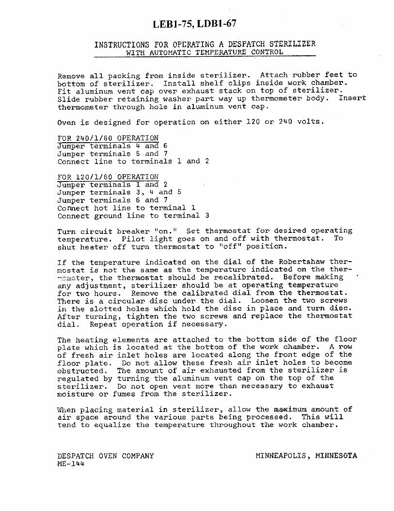
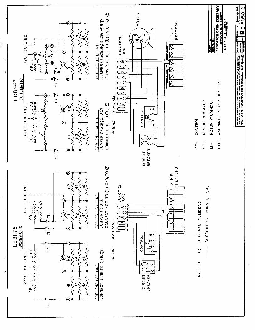
INSTRUCTIONS FOR OPERATING A DESPATCH STERILIZER
(MODELS LEB1-20, LEB1-27, LDB1-18, LDB1-23) Remove all packing from inside sterilizer. Attach rubber feet to bottom corners of sterilizer. Install shelf clips inside work chamber. Fit aluminum vent cap over exhaust stack on top of sterilizer. Slide rubber retaining washer part way up thermometer body. Insert thermometer through hole in aluminum vent cap. The twelve prong receptacle at the rear of the sterilizer is wired for 120/240 dual voltage operation. The operating voltage of the sterilizer is determined by the internal wiring of the power cord socket. The correct power cord for customer's operating voltage is shipped with each new sterilizer. To convert sterilizer from one voltage to the other, purchase power cord wired for the desired voltage from Despatch Industries. See "Power Cord Selection Guide" for part number. Set thermostat for desired operating temperature. Turn fan motor on (LDB1-18 and LDB1-23 only). Red pilot light goes on and off with thermostat. To shut heater off, turn thermostat to "off" position. If the temperature indicated on the dial of the Robertshaw thermostat is not the same as the temperature indicated on the thermometer, the thermostat should be recalibrated. Before making any adjustments, sterilizer should be at operating temperature for two hours. Pull knob and dial from thermostat shaft. Calibrating screw is located in center of thermostat shaft. If the temperature indicated on the dial of the Robertshaw is higher than the temperature indicated on the thermometer, turn calibrating screw counter-clockwise. If the temperature indicated on the dial of the thermostat is lower than the temperature indicated on the thermometer, turn calibrating screw clockwise. Replace knob and dial on the thermostat shaft. Repeat operation if necessary. The heating elements are attached to the bottom side of the floor plate which is located at the bottom of the work chamber. A row of fresh air inlet holes is located along the front edge of the floor plate. Do not allow these fresh air inlet holes to become obstructed. The amount of air exhausted from the sterilizer is regulated by turning the aluminum vent cap on the top of the sterilizer. Do not open vent more than necessary to exhaust moisture or fumes from the sterilizer. When placing material in sterilizer, allow the maximum amount of air space around the various parts being processed. This will tend to equalize the temperature throughout the work chamber.
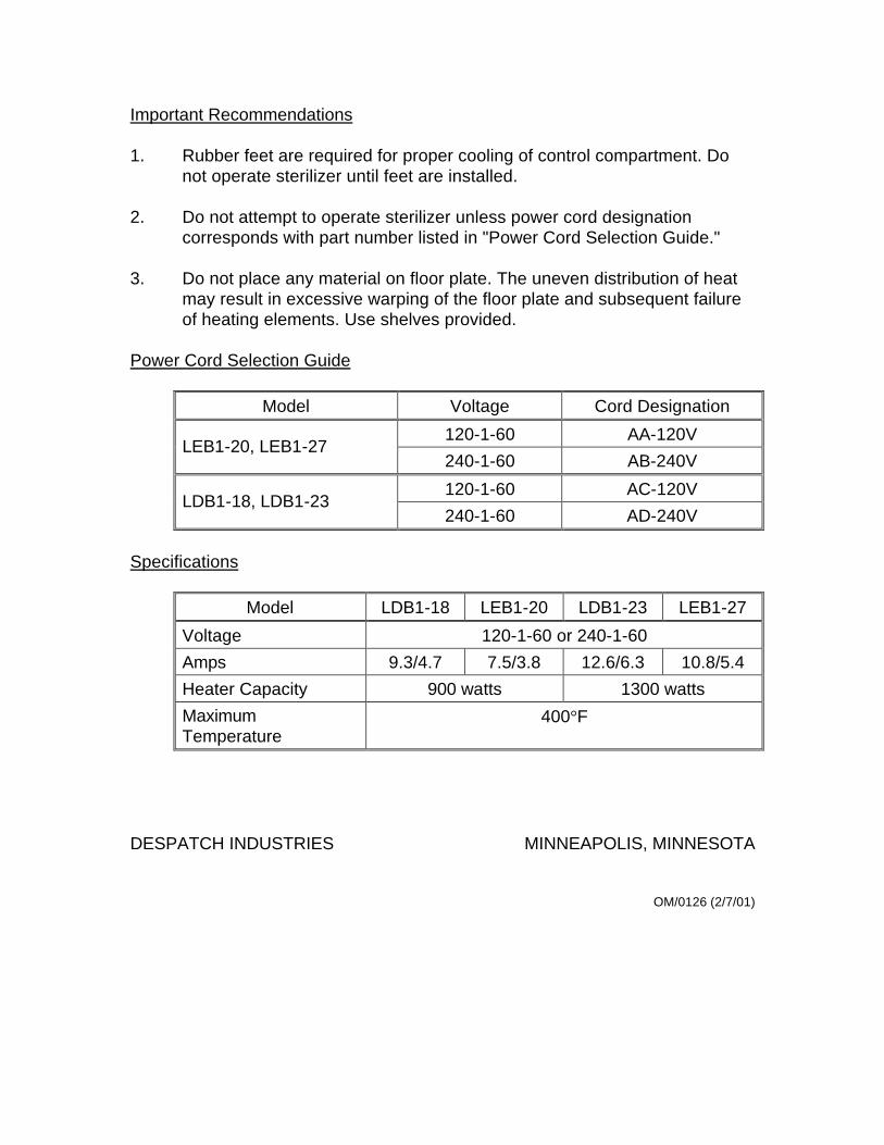
Important Recommendations 1. Rubber feet are required for proper cooling of control compartment. Do
not operate sterilizer until feet are installed. 2. Do not attempt to operate sterilizer unless power cord designation
corresponds with part number listed in "Power Cord Selection Guide." 3. Do not place any material on floor plate. The uneven distribution of heat
may result in excessive warping of the floor plate and subsequent failure of heating elements. Use shelves provided.
Power Cord Selection Guide
Model Voltage Cord Designation
120-1-60 AA-120V LEB1-20, LEB1-27
240-1-60 AB-240V
120-1-60 AC-120V LDB1-18, LDB1-23
240-1-60 AD-240V
Specifications
Model LDB1-18 LEB1-20 LDB1-23 LEB1-27
Voltage 120-1-60 or 240-1-60
Amps 9.3/4.7 7.5/3.8 12.6/6.3 10.8/5.4
Heater Capacity 900 watts 1300 watts
Maximum Temperature
400°F
DESPATCH INDUSTRIES MINNEAPOLIS, MINNESOTA
OM/0126 (2/7/01)


INSTRUCTIONS FOR OPERATING A DESPATCH STERILIZER WITH AUTOMATIC TEMPERATURE CONTROL
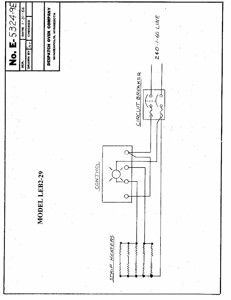
(MODELS LDB2-17, LDB2-28, LEB2-19, LEB2-29)
Remove all packing from inside sterilizer. Attach rubber feet to bottom of sterilizer. Install shelf clips inside work chamber. Fit aluminum vent cap over exhaust stack on top of sterilizer. Slide rubber retaining washer part way up thermometer body. Insert thermometer through hole in aluminum vent cap. Service connections are made to terminals in junction box in rear of oven. See additional instructions regarding operation of control instrument. Turn circuit breaker "on." Set thermostat for desired operating temperature. Pilot light goes on and off with thermostat. To shut motor off turn thermostat to "off" position. If the temperature indicated on the dial of the Robertshaw thermostat is not the same as the temperature indicated on the thermometer, the thermostat should be recalibrated. Before making any adjustments, sterilizer should be at operating temperature for two hours. Pull knob and dial from thermostat shaft. Calibrating screw is located in center of thermostat shaft. If the temperature indicated on the dial of the Robertshaw is higher than the temperature indicated on the thermometer, turn calibrating screw counter-clockwise. If the temperature indicated on the dial of the thermostat is lower than the temperature indicated on the thermometer, turn calibrating screw clockwise. Replace knob and dial on the thermostat shaft. Repeat operation if necessary. The heating elements are attached to the bottom side of the floor plate which is located at the bottom of the work chamber. A row of fresh air inlet holes is located along the front edge of the floor plate. Do not allow these fresh air inlet holes to become obstructed. The amount of air exhausted from the sterilizer is regulated by turning the aluminum vent cap on the top of the sterilizer. Do not open vent more than necessary to exhaust moisture or fumes from the sterilizer. When placing material in sterilizer, allow the maximum amount of air space around the various parts being processed. This will tend to equalize the temperature throughout the work chamber.
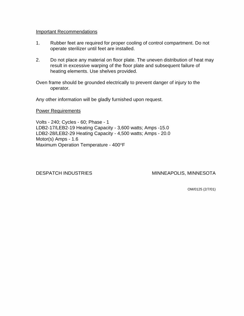
Important Recommendations 1. Rubber feet are required for proper cooling of control compartment. Do not
operate sterilizer until feet are installed. 2. Do not place any material on floor plate. The uneven distribution of heat may
result in excessive warping of the floor plate and subsequent failure of heating elements. Use shelves provided.
Oven frame should be grounded electrically to prevent danger of injury to the
operator. Any other information will be gladly furnished upon request. Power Requirements Volts - 240; Cycles - 60; Phase - 1 LDB2-17/LEB2-19 Heating Capacity - 3,600 watts; Amps -15.0 LDB2-28/LEB2-29 Heating Capacity - 4,500 watts; Amps - 20.0 Motor(s) Amps - 1.6 Maximum Operation Temperature - 400°F DESPATCH INDUSTRIES MINNEAPOLIS, MINNESOTA
OM/0125 (2/7/01)