pallet stoppers - weforma · pallet stoppers deceleration technology. ... wps 500 20 15,0 154 124...
TRANSCRIPT
www.weforma.com26.4.2018
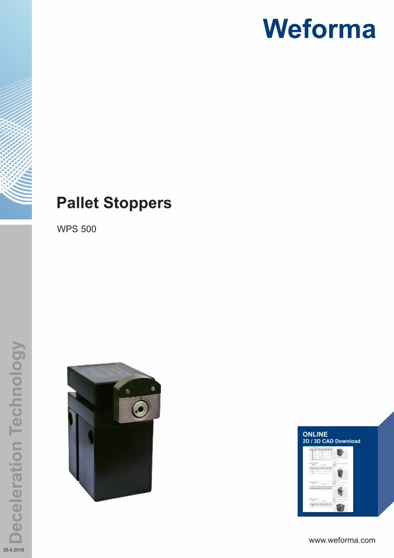
WPS 500
ONLINE2D / 3D CAD Download
Pallet Stoppers
Dec
eler
atio
n Te
chno
logy
www.weforma.com26.4.2018
PERFORMANCE
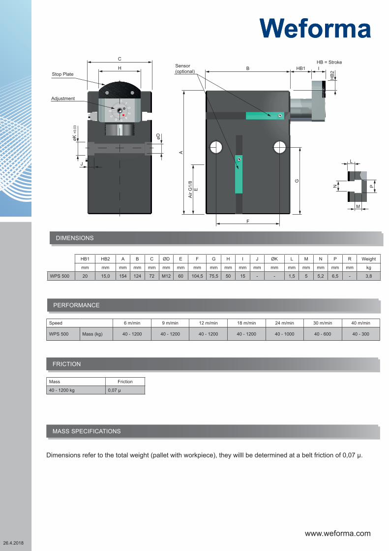
DIMENSIONS
0 1 2 3 4 5 6 7 8
Stop Plate
Adjustment
H
C
J
øK +
0.03
øD
Sensor(optional) B HB1 I
HB
2
A
Air
G1/
8E
G
F
HB = Stroke
M
L
N P FRICTION
HB1 HB2 A B C ØD E F G H I J ØK L M N P R Weight
mm mm mm mm mm mm mm mm mm mm mm mm mm mm mm mm mm mm kg
WPS 500 20 15,0 154 124 72 M12 60 104,5 75,5 50 15 - - 1,5 5 5,2 6,5 - 3,8
Speed 6 m/min 9 m/min 12 m/min 18 m/min 24 m/min 30 m/min 40 m/min
WPS 500 Mass (kg) 40 - 1200 40 - 1200 40 - 1200 40 - 1200 40 - 1000 40 - 600 40 - 300
Mass Friction
40 - 1200 kg 0,07 µ
MASS SPECIFICATIONS
Dimensions refer to the total weight (pallet with workpiece), they willl be determined at a belt friction of 0,07 µ.

www.weforma.com26.4.2018
Working Pressure 4 - 8 bar
Compressed Air treated
Tube Diameter 6 - 8 mm
Stroke horizontal: WPS 500
20 mm
Stroke vertical: WPS 500
15 mm
Friction: 0,07 mü between palett and conveyor band
Function: single-activeopen pneumaticclose spring force
Pull down force (- spring force): 560 N at 6 bar
Air consumption: ca. 0,03l air at 6 bar
Operation - AirPneumatic, filtered air: dry, oiled or unoiledPressurized air according ISO in 8573-1: Grade 4
Temperature-10 °C bis +80 °C
• Precise deceleration and singulation of pallets• Adjustable hydraulic deceleration with pneumatic
piston return• Masses up to 1.200 kg and speeds up to 40 m/min• Housing: aluminium, black anodized, Stop: nickel plated• Hardened stop• Sensor for end postion (optional)• Special version: pallet stopper for clean room Cl. 5 (ISO),
Cl. 100 (US), Cl. 3 (VDI)• RoHS compliant Directive 2002/95/EC
Benefits
Technical Data

www.weforma.com26.4.2018
0 1 2 3 4 5 6 7 8
Anschlag / Stop Plate
Einstellung /Adjustment
Technical DataMaximum traffic jam pressure• Depending on friction between pallet and transfer system• Depending on friction between pallet and the poster• Depending on the position of the pallet‘s poster• Depending on the surroundings conditions
Enquiry optionsThe WPS 500 owns 4-T grooves for various electronic query.About these enquiry options the positions of the poster arerecognised.
MaintenanceNo maintenance works must be carried out.Compressed air: dry, oiled or unoiled; afterISO in 8573-1: Grade 4.The area around the pallet stopper must be cleaned and freefrom shavings, to be able to guarantee exact positioning ofthe tool bearer.
Piston diameter (for lowering)WPS 500 Piston Ø32
Precise settingEnergy absorption and speed kan get set at the front side of the Pallet Stopper scale 0-80 = low effective mass8 = high effective massThe shock absorber in the palette stopper is stopped in the plant on 8.Is too high the damping force for the application, the clamping screw, in the adjusting screw, with the wrench must be solved. Then can turn the damping force by of the adjusting screw are adjusted. This should follow in several steps. If the shock absorber is then the clamping screw again screwed is properly stopped, around independent shifting that of the damping force to prevent.

www.weforma.com26.4.2018
-The palette stopper is on both sides mountable for the connection 2x PSB 500 are required
Screw M8x85DIN 912; SW6Firmness class: 8.8; verzinkt
Nut for T-Groove 10xM8DIN 508Firmness class: 10
Centring bushø10xø8x6,5
Connection clause PSB 500
14
15
16
17
18
1 PSB 500 Fastening set
Mounting
Air Connection
Accessories
Air Connection G1/8at the back side
14 VWI1/8-6 G1/8-6 Stud elbow
14 VWI1/8-8 G1/8-8 Stud elbow
15 VGR1/8-6 G1/8-6 Male stud
15 VGR1/8-8 G1/8-8 Male stud
16 VWS1/8-6 G1/8-6 Single banjo
16 VWS1/8-8 G1/8-8 Single banjo
17 VDR1/8-6 G1/8-6 Flow control regulator
17 VDR1/8-8 G1/8-8 Flow control regulator
18 VWL1/8-6 G1/8-6 Stud elbo, extended
18 VWL1/8-8 G1/8-8 Stud elbo, extended

www.weforma.com26.4.2018
(WPS 500: Art.Nr. / Code PS514)
57 90 120
85,5
Ø12,5
M8
t=20
90
123,5
12 PS514 Mounting Flange
Sensors
Using this sensor air connection on the front
2 3 4 5
6
2
3
4
5
10
6
6
798
7
9
87
9
8
7
9
87
9
8
7 98
7 98
798
1920
117,5
Mounting Flange
2 N 10 Sensor, inductiv, 2,5 m cabel
3 N 11 Sensor, inductiv, 5 m cabel
4 N 15 Sensor with plug, inductiv, Ø 8mm, 0,3 m cabel
5 N 16 Sensor with knurled nut, Ø 8mm, inductiv, 0,3 m cabel
6 N 20 Sensor, inductiv
7 KS 60 Cable with plug Ø 8mm
8 KS 25 Cable with plug 2,5 m, Ø 8mm
9 KS 50 Cable with plug 5 m, Ø 8mm
10 PS500-15 Position sensing WPS-500, top and bottom (optional)
19 PS500-16 Position sensing WPS-500, Retracted stop (optional)
20 PS500-17 Position sensing WPS-500, Palett (optional)
Standard version: without preparation for proximity switch (e.g. WPS 500)„NV“ Version: with preparation for proximity switch (e.g. WPS 500-NV)The proximity switch must be ordered separatly.
Stop plate
(WPS 500: Art.Nr. / Code PS500-1)Steel (spare part)
11 PS500-1 Stop plate, steel, hardened (for replacement)
Ordering information proximity switch
www.weforma.com26.4.2018
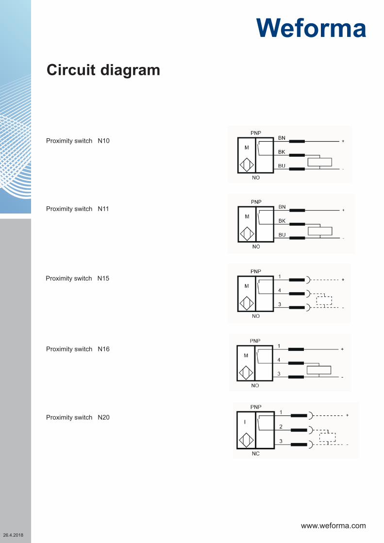
Proximity switch N10
Proximity switch N11
Proximity switch N15
Proximity switch N16
Proximity switch N20
Circuit diagram
www.weforma.com26.4.2018
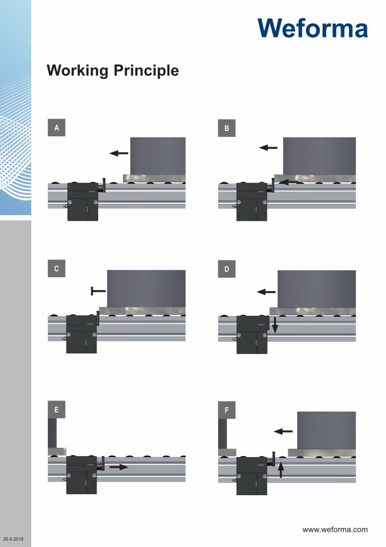
DC
FE
BA
Working Principle

www.weforma.com26.4.2018
1
4
5
3 2
Shock AbsorberCode: E30510-500
2
6
7 2
7
Shock absorber changeIf the damping force of the shock absorber are not any more enough, he must be exchanged.
1. To be able to take the shock absorber from the palette stopper both screws must fix them the hold metal areunscrewed.2. The hold metal is pushed upwards from the case cover. The headless screw in the admission socket to thefixation of the shock absorber serves must be completely unscrewed.3. If then the clamping screw is fixed in the adjusting screw,4. is able the shock absorber, with a wrench (SW 2.5) are unscrewed forwards from the palette stopper.5. To the installation of the new shock absorber you proceed in the reverse order.By mounting the holdplate (2) in the casecover (6), the guidering (7) of the Shock Absorber has to be mounted inthe groove of the holdplate (see fig. 5)
1 2 3
4 5

www.weforma.com26.4.2018
Safety InstructionsAttention
For all work on or with the pallet stopper WPS, the data sheet must be observed. The work must be performed by trained, skilled personal.
Electrical connections must be in accordance with VDE0100or the relevant national regulations.
Repair and maintenance:Electricity and compressed air must be shut down.The work area is to prevent against accidentally switch on of electricity and compressed air.
Reference temperature for all technical information: 20°CAt a higher temperatures the energy absorption or torque is reduced.
Maximum load:If multiple pallets piled up in the transfer system and later given free individual, it must be ensured that when releasing the first pallet, the total mass of the following palettes exceed the maximum weight to be stopped at any time (see table: Performance)
Designated useStopping and positioning of one or several pallet(s) at the stop plate of the pallet.The pallet stopper WPS 500 is designed for the separation of pallets. A load may occur only in the direction of work. The pallet stopper WPS 500 is not suitable for explosion-threatedareas. Without written acceptance of Weforma the WPS 500 can not be be used as a safety device.The position of the stop must be detected.
Liability - Guarantee
All warranty and liability claims expire at non-designated use.This applies even if no original spare parts are used.
Environment protection
The replacement of worn parts must be paid to proper disposal.Wearing parts and complete stopper can be sent toWeforma for free disposal.