palm springs fire department development guidelines
TRANSCRIPT

2013 California Fire Code Appendixl
PALM SPRINGS FIRE DEPARTMENT DEVELOPMENT GUIDELINES
PALM SPRINGS FIRE DEPARTMENT 300 NORTH EL CIELO ROAD PALM SPRINGS, CA, 92262
FIRE PREVENTION BUREAU CONTACTS
DEPUTY CHIEF/FIRE MARSHAL JIM WEBB (760) 323-8187 [email protected]
PLANS EXAMINER II BOB ROSE {760) 323-8184 [email protected]
FIRE PREVENTION SECRETARY JANET VINES-MOTT (760) 323-8186 [email protected]
I 82

TABLE OF CONTENTS
SCOPE ~
WATER AGENCY I DISTRICT CONTACTS.
PLANS AND PERMITS .§.
PRIVATE FIRE SERVICE MAINS I
FIRE SPRINKLER SYSTEMS- NFPA 13 .1Q
FIRE SPRINKLER SYSTEMS- NFPA 13R . ~
FIRE SPRINKLER SYSTEMS- NFPA 13D . 17
INSPECTIONS AND TESTS . ~
EMERGENCY ACCESS & GATES
FIRE APPARATUS ACCESS ROADS ~
PHOTOVOL T AIC GUIDELINES
2 83

SCOPE
This guideline has been developed to assist development applicants, architects and contractors in determining the minimum requirements for fire protection systems, emergency access/gates, fire apparatus access roads and solar photovoltaic systems. It will provide the minimum design, installation, testing, and inspection procedures in the City of Palm Springs based on the following:
• Palm Springs Municipal Code, Chapter 8.04 of Title 8 and Chapter 11.02 of Title 11.
• California Fire Code 2013 Edition - CCR Title 24, Part 9, adopted as hereinafter modified including Appendix Chapter 4, Appendix A, B, BB, C, CC, F, H, I, J, K, L, M and N.
• California Code of Regulations (CCR)- Title 19.
• California Building Code 2013 Edition - CCR Title 24, Part 2.
• FM - Factory Mutual Global
• National Fire Protection Association Standards - adopted and/or most recent Editions including but not limited to:
NFPA2: NFPA 11: NFPA 12: NFPA 12A: NFPA 13: NFPA 13D:
NFPA 13R:
NFPA 14: NFPA 15: NFPA 16:
NFPA 17: NFPA 17A: NFPA 20: NFPA 22: NFPA 24:
NFPA 25:
NFPA 30: NFPA 30A: NFPA 30B: NFPA 32: NFPA33:
Hydrogen Technologies Code, 2011 Edition Standard for Low-, Medium-, and High-Expansion Foam Standard on Carbon Dioxide Extinguishing Systems Standard on Halon 1301 Fire Extinguishing Systems Standard for the Installation of Sprinkler Systems Standard for the Installation of Sprinkler Systems in One- and Two-Family Dwellings and Manufactured Homes Standard for the Installation of Sprinkler Systems in Residential Occupancies up to and Including Four Stories in Height Standard for the Installation of Standpipe and Hose Systems Standard for Water Spray Fixed Systems for Fire Protection Standard for the Installation of Foam-Water Sprinkler and Foam-Water Spray Systems Standard for Dry Chemical Extinguishing Systems Standard for Wet Chemical Extinguishing Systems Standard for the Installation of Stationary Pumps for Fire Protection Standard for Water Tanks for Private Fire Protection Standard for the Installation of Private Fire Service Mains and their Appurtenances Standard for the Inspection, Testing, and Maintenance of Water-Based Fire Protection Systems Flammable and Combustible Liquids Code Code for Motor Fuel Dispensing Facilities and Repair Garages Code for the Manufacture and Storage of Aerosol Products Standard for Drycleaning Plants Standard for Spray Application Using Flammable or Combustible Materials
3 84

NFPA34:
NFPA 37:
NFPA 51:
NFPA 51B: NFPA52: NFPA 54: NFPA55: NFPA58: NFPA 59A:
NFPA 70: NFPA 72: NFPA80: NFPA86: NFPA88A: NFPA92: NFPA92A NFPA92B: NFPA96:
NFPA 110: NFPA 111: NFPA 140:
NFPA 160: NFPA204: NFPA221: NFPA232: NFPA 241: NFPA 400: NFPA 407: NFPA 409: NFPA 410: NFPA434: NFPA 520: NFPA 560:
NFPA664:
NFPA 704:
NFPA 720:
NFPA 731: NFPA 750: NFPA853: NFPA909:
Standard for Dipping, Coating and Printing Processes Using Flammable or Combustible Liquids Standard for the Installation and Use of Stationary Combustion Engines and Gas Turbines Standard for the Design and Installation of Oxygen-Fuel Gas Systems for Welding, Cutting, and Allied Processes Standard for Fire Prevention During Welding, Cutting, and Other Hot Work Vehicular Gaseous Fuel Systems Code National Fuel Gas Code Compressed Gases and Cryogenic Fluids Code Liquefied Petroleum Gas Code Standard for the Production, Storage, and Handling of Liquefied Natural Gas (LNG) National Electric Code National Fire Alarm Code® Standard for Fire Doors and Other Opening Protectives Standard for Ovens and Furnaces Standard for Parking Structures Standard for Smoke Control Systems Standard for Smoke Control Systems Utilizing Barriers and Pressure Differences Standard for Smoke Management Systems in Malls, Atria, and Large Spaces Standard for Ventilation Control and Fire Protection of Commercial Cooking Operations Standard for Emergency and Standby Power Systems Standard on Stored Electrical Energy Emergency and Standby Power Systems Standard on Motion Picture and Television Production Studio Soundstages, Approved Production Facilities, and Production Locations Standard for the Use of Flame Effects Before an Audience Standard for Smoke and Heat Venting Standard for High Challenge Fire Walls, Fire Walls, and Fire Barrier Walls Standard for the Protection of Records Standard for Safeguarding Construction, Alteration, and Demolition Operations Hazardous Materials Code Standard for Aircraft Fuel Servicing Standard on Aircraft Hangars Standard on Aircraft Maintenance Code for the Storage of Pesticides Standard on Subterranean Spaces Standard for the Storage, Handling, and Use of Ethylene Oxide for Sterilization and Fumigation Standard for the Prevention of Fires and Explosions in Wood Processing and Woodworking Facilities Standard System for the Identification of the Hazards of Materials for Emergency Response Standard for the Installation of Carbon Monoxide (CO) Detection and Warning Equipment Standard for the Installation of Electronic Premises Security Systems Standard on Water Mist Fire Protection Systems Standard for the Installation of Stationary Fuel Cell Power Systems Code for the Protection of Cultural Resources Properties - Museums, Libraries, and Places of Worship
4 85

NFPA 914: NFPA 1123: NFPA 1126: NFPA 1141:
NFPA 1142:
NFPA2001:
Code for Fire Protection of Historic Structures Code for Fireworks Display Standard for the Use of Pyrotechnics Before a Proximate Audience Standard for Fire Protection Infrastructure for Land Development in Suburban and Rural Areas Standard on Water Supplies for Suburban and Rural Fire Fighting
Standard on Clean Agent Fire Extinguishing Systems
• UL- Underwriters Laboratories Inc.
The Authority Having Jurisdiction in determining compliance with the above codes and standards shall be the Palm Springs Fire Department. The fire code official may waive or modify these requirements based on unforeseen circumstances or other mitigating factors.
WATER AGENCY/DISTRICT CONTACTS SERVICING PALM SPRINGS
Service Area Palm Springs south of Interstate 10
Desert Water Agency 1200 S. Gene Autry Trail Palm Springs, CA 92264
(760) 323-4971 www.dwa.org
Service Area Palm Springs north of Interstate 10
Mission Springs Water District 6657 5 2"d Street
Desert Hot Springs, CA 92240 (760) 329-6448 www.mswd.org
1.0 WATER AGENCY/DISTRICT REQUIREMENTS
1.1 Contractors or developers will contact the Water Agency/District and request the following information to facilitate designing private fire service mains and fire sprinkler systems:
• Water service size, material type and schedule. • Length of service, fittings and valves installed. • Water meter manufacturer, model and size (if fire service is metered) • Backflow manufacturer, model, size and arrangement.
1.2 The Water Agency/District will assist the Fire Prevention Bureau in providing flow information for water mains or fire hydrants:
• Static pressures. • Dynamic/residual pressures. • Gallons per minute. • Water main size and configuration. • Fire Hydrant Identification Numbers used in testing and street address or location
description. Indicate Fire Hydrant Identification Number where pressure readings were taken.
5 86

• The Fire Prevention Bureau attempts to conduct water flow capability tests and static pressure readings once each week with a Water Agency/District representative. Contractors are required to call 760-323-8186 to request water hydrant flow tests and static pressure readings.
2.0 PLANS ANQ pERMITS
2.1 When there are significant changes in occupancy, water supply, storage heights, type and quantity of storage, storage configurations, Tenant Improvements or any other changes which may affect the fire sprinkler system design, the owner, tenant or contractor shall submit plans and secure permits.
2.2 Complete plans for private fire service mains or fire sprinkler systems should be submitted for approval well in advance of installation. Plan reviews can take up to 20 working days. Submit a minimum of three (3) sets of drawings for review. Upon approval, the Fire Prevention Bureau will retain one set.
2.3 Plans shall be submitted to:
City of Palm Springs Building and Safety Department 3200 E. Tahquitz Canyon Way Palm Springs, CA 92262
Counter Hours: Monday- Thursday, 8:00 AM - 6:00 PM
A minimum $208.00 deposit for Plan Check and Inspection Fees is required at the time of Plan Submittal. The final fee is based on fees established by Resolution of the Palm Springs City Council.
2.4 Complete listings and manufacturer's technical data sheets for all system materials shall be included with plan submittals. All system materials shall be UL listed or FM approved for fire protection service and approved by the Fire Prevention Bureau prior to installation.
2.5 Plans shall indicate all necessary engineering features, including all hydraulic reference nodes, pipe lengths and pipe diameters as required by the appropriate codes and standards. Plans and supportive data (calculations and manufacturer's technical data sheets) shall be submitted with each plan submittal. Complete and accurate legends for all symbols and abbreviations shall be provided on the plans.
The contractor shall submit a copy of their California Contractors License, Workers Compensation Insurance Certificate and Palm Springs Business License with each submittal. Contractors License and Workers Compensation Insurance shall be verified with the Contractor's License Board. The following contractors shall install the appropriate system components:
(A) (C-16)
General Engineering Contractor. Fire Protection Contractor.
6 87
(C-34) (C-36)
Pipeline Contractor. Plumbing Contractor.
2.6 "As Built Drawings and Calculations" will be required when there is a significant deviation from approved drawings and calculations.
2. 7 The Fire Prevention Bureau will determine the fire flow requirements, number of fire hydrants, and hydrant spacing.
3.0 PRIVATE FIRE SERVICE MAJN
3.1 NFPA 24 shall establish the minimum requirements for the installation of private fire service mains and their appurtenances supplying automatic sprinkler systems, open sprinkler systems, water spray fixed systems, foam systems, private hydrants, monitor nozzles or standpipe systems with reference to water supplies, private hydrants and hose houses.
3.2 Private fire service mains shall be not less than eight (8) inches in diameter when serving private fire hydrants and fire sprinkler systems.
3.3 Piping with a minimum rating of class 200 installed to NFPA 24 standards is required for all private fire service mains.
3.4 All thrust blocks on private fire service mains, private fire hydrant lines and fire sprinkler laterals shall be calculated as required by NFPA 24, or use Water Agency/District Drawings. Calculations shall be submitted and the resulting dimensions of thrust blocks shall be shown on the plans. Restrained Joint Systems are allowed in lieu of thrust blocks. Minimum design working pressure shall be 200 PSI. Special design considerations may be required with high static pressures or lines in which fire pumps are installed.
3.5 Private fire service mains when supplying three (3) or more fire hydrants shall be designed with a looped water supply.
3.6 In order to isolate the fire sprinkler underground lateral from any private fire hydrant system, a non-indicating listed underground gate valve with an approved roadway box shall be required.
3.7 Non-indicating listed underground gate valves with approved roadway boxes shall be required to sectionalize no more than two commercial buildings, three residential buildings or two private fire hydrants in private fire service mains. Any deviation will require the Fire Prevention Bureau approval.
3.8 On site fire hydrants and Fire Department Connections located less than three (3) feet behind the face of a curb or when no curb is provided shall be protected by guard posts set in concrete to the following specifications: • Constructed of steel not less than 4 inches in diameter and concrete filled. • Spaced not more than 4 feet between posts on center. • Set not less than 3 feet deep in a concrete footing of not less than a 15-inch
diameter.
7 88

• Set with the top of the posts not less than 3 feet above ground. • Located not less than 3 feet from the fire hydrants, post indicator valves and Fire
Department connections. • All guard posts shall be painted yellow. (Rust-Oleum safety yellow #2149 or
equivalent). 3.9 The installing contractor shall provide a completed "Contractors Material & Test
Certificate for Underground Piping" as required by NFPA 24 (2013 edition).
Double Check Detector Assemblies (Private)
3.10 All Double Check Detector Assemblies shall be UL listed/FM approved for fire protection service in compliance with NFPA 24.
3.11 All Double Check Detector Assemblies shall be installed with two tamper switches and electrically monitored at a UL listed central station service, when there are: • 20 or more fire sprinkler heads. • Fire sprinkler supervision and alarm, fire alarm or security systems are installed.
3.12 All Double Check Detector Assemblies shall be provided with a chain and breakaway security lock. A key shall be kept in the spare sprinkler head box and KNOX key box.
3.13 Reduced pressure zone assemblies or reduced pressure detector assemblies shall not be installed in private fire service mains and fire sprinkler systems.
Fire Department Connections
3.14 Fire Department Connections shall be installed at apparatus access roads in locations approved by the Fire Prevention Bureau. Check with the Fire Prevention Bureau prior to plan submittal. The Fire Department Connection shall extend between 30" and 36" above finished grade.
3.15 Fire Department Connections shall be visible, accessible, and installed in approved locations downstream of all Double Check Detector Assemblies. Fire Department connections shall be located within 30 feet of a public fire hydrant. Exceptions may be made by the fire code official.
3.16 Fire Department Connections shall be equipped with KNOX locking protective caps. Contact the Fire Prevention Bureau Secretary at (760) 323-8186 for a KNOX Application Form.
3.17 When the total sprinkler system demand, including hose allowance, is less than 1,000 G.P.M., the Fire Department Connection riser shall be 4" in nominal diameter and shall have a standard 2-way threaded 2 y,• connection.
3.18 When the total sprinkler system demand, including hose allowance, is 1 ,000 GPM to 1,199 G.P.M., the Fire Department Connection riser shall be 6" in nominal diameter and shall have a standard 3-way threaded 2 y,• connection.
8 89

3.19 When the total sprinkler system demand, including hose allowance, is greater than 1 ,200 G.P.M., the Fire Department Connection riser shall be 6" in nominal diameter and shall have a standard 4-way threaded 2 W connection.
3.20 In a building complex, where two or more buildings are served, the identification of which building is served by separate Fire Department Connections; the Fire Prevention Bureau will require signs of substantial construction to be posted at each Fire Department Connection identifying the respective buildings served. The minimum letter size shall be 1" on a contrasting background.
3.21 Fire Department Connections shall be painted red (Rust-Oleum Safety Red # 2163 or equivalent).
3.22 Fire Department Connection piping shall be ductile iron from the private fire service main to the Fire Department Connection check valve above ground. The pipe from the Fire Department Connection check valve to the Fire Department Connection shall be galvanized steel pipe. The NFPA 13R Fire Department Connection piping shall be copper from the private fire service main.
Fire Hydrants (Private)
3.23 Commercial fire hydrants with 4" x 2 1/2" x 2 1/2" outlets are required when fire flow demand is 1,500 GPM or greater. Residential fire hydrants with 4" x 2 Y." outlets are required when the fire flow demand is less than 1500 GPM. Existing residential fire hydrants that are located within 250' of a residential property line do not need to be upgraded to commercial fire hydrants if that hydrant/s can provide the required fire flow.
3.24 Private fire hydrants shall be painted red (Rust-Oleum Safety Red# 2163 or equivalent).
3.25 Blue reflective markers shall be installed to identify location of fire hydrants. These markers shall be visible from both directions of vehicle travel.
3.26 Hydraulic calculations shall be provided for all private fire hydrant systems. Calculations shall be calculated back to the point of the flow test. The fire hydrant system shall meet the fire flow requirements as required by the California Fire Code (2013 Edition).
3.27 When the private fire service main serves both fire sprinkler system(s) and private fire hydrant(s), the hydraulic calculation shall include the fire hydrant flow rate with associated private fire hydrant(s) and fire sprinkler flow rate for a minimum design of 20 PSI residual pressure for the fire hydrant (s).
Water Plans and Water Main Installation (Private)
3.28 Provide the following notes on private the fire service water main plans:
FIRE DEPARTMENT NOTES: 1. The installation of the private fire service mains shall comply with:
• NFPA 24 • California Building Code (2013 Edition). • California Fire Code (2013 Edition).
9 90

• Palm Springs Fire Prevention Development Guidelines, Appendix L
2. No combustibles shall be delivered to building job site prior to the water mains and fire hydrants being operational.
3. The following inspections are required: • Thrust block pre-pour, trench, and backfill inspection. • Underground hydrostatic test - 200 PSI for two hours. • Underground flush. • Underground final. A completed and signed "Contractors Material & Test
Certificate for Underground Piping" form per NFPA 24 (2013 Edition) • All inspections will be conducted on Tuesdays or Thursdays. Sprinkler
contractors must request inspections through the project Superintendents.
TO SCHEDULE INSPECTIONS CALL the Fire Prevention Bureau at (760) 323·8186 AT LEAST 48 HOUR$ PRIOR TO THE REQUESTED INSPECTION DATE AND TIME. Inspections are completed Tuesday and Thursday.
4. All Double Check Detector Assemblies shall be installed with two tamper switches and electrically monitored at a UL listed central receiving station service, when there are: • 20 or more fire sprinkler heads. • Fire alarms or security systems installed.
5. Ductile iron underground piping shall be installed beginning five feet from a building and continue into the building.
6. No joints shall be installed under the building.
7. The civil engineer who designed the water system hereby certifies that this water system is in accordance with the requirements as prescribed by the Fire Prevention Bureau, the California Fire Code (2013 Edition) and NFPA 24.
8. Breakaway spools or breakaway bolts are required.
4.0 FIRE SPRINKLER SYSTEMS· NFPA 13
Controls
4.1 All control valves shall be UL Listed indicating valves.
4.2 All valves controlling the water supply for automatic sprinkler systems, pumps, tanks, water levels and temperatures, critical air pressures, and water-flow switches on all sprinkler systems shall be electrically supervised by a listed fire alarm control unit and monitored at a UL listed central station service.
4.3 An approved audible sprinkler flow alarm (Wheelock horn/strobe with WBB back box or equal) shall be provided on the exterior of the building in an approved location. A second horn/strobe shall be installed in the interior of the building in a normally occupied location. In multiple suite buildings, additional interior horn/strobes shall be installed in all
10 91

suites with 50 or more occupant load. Power shall be provided from a fire alarm control unit.
4.4 A dedicated electrical circuit with a circuit breaker lock shall be required for the listed fire alarm control unit.
Fire Sprinkler Risers (NFPA 13)
4.5 When more than one fire sprinkler riser is served by a single private fire service main lateral, a separate system riser with a UL Listed indicating control valve, riser check valve, water flow indicator and main drain is required for each fire sprinkler riser.
4.6 In multi-story buildings, each floor shall have a sectional riser with a UL Listed indicating control valve, riser check valve, water flow indicator and main drain.
4. 7 In order to provide access to the riser for future maintenance and repair, all fire sprinkler system riser locations shall provide with a minimum 18" clearance to each side and to the front of the riser. If a riser is to be concealed by means of a wall or closet, access to the riser shall be provided by means of a door with minimum dimensions of 2'-6" x 6'-8".
Piping and Hangers (NFPA 13)
4.8 Threaded steel pipe shall have a minimum wall thickness of "Dyna-Thread" or Schedule 30 for branch lines less than 2 1/2" and Schedule 40 for all other piping.
4.9 Rolled groove and welded steel pipe shall have a minimum wall thickness of Schedule 10.
4.10 The discharge area for the main drain and inspector's test valve shall be protected with a concrete splash pad to prevent damage to landscaping during periodic testing or other appropriate means.
4.11 Trapeze hangers shall be installed according to NFPA 13. The acceptable trapeze methods as outlined in NFPA 13 shall be Schedule 10, Schedule 40 or angles. All other methods will not be accepted unless a structural engineer or the architect of record provides to the Fire Prevention Bureau calculations and diagrams wet stamped and signed for each application.
4.12 Where a beam or joist thickness will not accommodate a fastener of a required length, a through bolt with the required diameter of the bolt and washer will be acceptable. Allthread rod is not acceptable for the required bolt.
4.13 Lag bolts and screws are not acceptable for seismic bracing.
4.14 Seismic sway bracing shall use Schedule 40 pipe as a minimum.
Design (NFPA 13)
II 92

4.15 For commercial and industrial "Shell Buildings", with the potential for high-pile storage and/or wherein no specific end use is identified at the time of plan check, the sprinkler system shall provide a minimum density of .45 GPM/square foot for a 2,000 square foot design area. 286 deg. F sprinkler heads shall be used in these buildings. Roof coverage over mezzanine areas shall also be built to this standard. Any deviation from this requirement will require the Fire Prevention Bureau approval.
4.16 It is incumbent upon the sprinkler system designer to advise the building owner that the above density and design area are minimums for shell buildings; and that increases in sprinkler protection may be required based on future occupancy hazard classification, storage commodity classification, and storage configuration according to NFPA 13 and the California Fire Code (2013 Edition).
4.17 When a shell building is built without a hard lid or T-bar ceiling, the upright fire sprinklers shall be designed to the unfinished ceiling height and the density and design area for the required floor area.
4.18 Fire sprinkler design shall be limited to 90 percent of the available water supply.
4.19 Non-combustible construction shall be as defined by the California Building Code (2013 Edition). Wood frame construction shall be considered combustible construction regardless of materials used for surface covering.
4.20 Sprinklers with a temperature rating of not less than an intermediate temperature rating are required in all main electrical panel and meter rooms. No combustible materials shall be stored in these rooms.
4.21 Light fixtures, soffits and other potential obstructions shall not interfere with the spray patterns of fire sprinklers. The sprinkler contractor shall insure that the type and location of potential obstructions is considered in the design and installation of the system. The sprinkler contractor is responsible for coordinating and resolving conflicts in coverage patterns.
4.22 Fire sprinklers shall not be installed directly below automatic smoke and heat vents.
4.23 Inspector Test valve access panels and doors to fire sprinkler riser rooms shall have a signs with an appropriate description.
4.24 All electrical rooms, upright sprinklers at the roof or in the attic space, non-conditioned rooms or exterior sprinkler heads shall be 200- 212 degree Fahrenheit heads.
4.25 If the attic space is less than 36 inches height and combustible construction, all upright fire sprinkler heads shall be to TYCO CC-2, AP or equal heads per NFPA 13, Section 8.15.1.6
Plans (NFPA 13)
4.26 Complete detailed work sheets and computer hydraulic calculations as required by NFPA 13 shall be included with all submittals for hydraulically designed sprinkler systems. Calculations shall extend to the point at which the water supply data was determined.
12 93

4.27 Water supply curves and system demand curves, including underground friction loss, hose allowance, and applicable in-rack sprinkler demand, shall be plotted on semilogarithmic graph paper or computer generated graphs. Sprinkler system design, including hose demand, shall be limited to 90 percent of the available water supply. Water supply data may be obtained from the Fire Prevention Bureau by calling 760-323-8186.
4.28 If installed piping is six (6) inches or larger, structural load calculations will be required for the structural elements/systems supporting the load.
4.29 Provide separate drawings for the piping plan and reflective ceiling plan.
4.30 Provide a fire sprinkler legend including sprinkler symbol, Manufacturer, Sprinkler Identification Number (SIN), model, style, K-factor, degree, finish, escutcheon and quantity.
4.31 Provide the occupancy type of each room, ceiling heights and ceiling slopes with direction, slope pitch and ceiling height at the beginning of the slope as applicable.
4.32 Provide soffit and ceiling pocket details including widths, depths and heights.
4.33 Provide Seismic Bracing Calculations on the drawings per NFPA 13 using Cp of 0.74 and 1/r Ratio of 200. Separate Seismic Bracing Calculations shall be provided for lateral and longitudinal braces and each pipe size. Show details of the seismic bracing and branch line restraints on the drawings. Piping individually supported by rods less than 6 in. long measured between the top of the pipe and the point of attachment to the building structure shall not be used in lieu of seismic lateral bracing.
4.34 Hydraulic Plate information shall be included on the drawings.
4.35 Provide calculations of the Number of Sprinklers to Calculate and the Number of Sprinklers on a Branch Line and list Assumed Remote Area Sq. Ft.
4.36 Mark on the drawings the Most Hydraulically Demanding Remote Area; and Zone of Influence for lateral and longitudinal seismic bracing.
4.37 In order to provide access to the riser for future maintenance and repair, all fire sprinkler system riser locations shall provide with a minimum 18" clearance to each side and to the front of the riser. If a riser is to be concealed by means of a wall or closet, access to the riser shall be provided by means of a door with minimum dimensions of 2'-6" x 6'-8".
4.38 The location of the Fire Department Connection shall be within thirty (30) feet of a public commercial fire hydrant with 4"x2Y:."x2Y:z" outlets.
4.39 All Fire Department Connections shall have KNOX locking protective caps. Contact the fire prevention secretary at (760) 323-8186 for a KNOX application form.
4.40 Pipe Schedule Design shall not be used in existing systems, extension of existing systems and new systems.
13 94

4.41 Provide the following notes on fire sprinkler plans:
FIRE DEPARTMENT NOTES (NFPA 13)
1. The installation of the sprinkler systems or modifications to existing sprinkler systems shall comply with:
• NFPA 13. • California Fire Code (2013Edition) • California Building Code (2013Edition) • The City of Palm Springs Municipal Code Chapter 11.02 of Title 11. • Palm Springs Fire Department Development Guidelines, Appendix L
2. The Fire Prevention Bureau will require the following inspections and tests as a minimum:
• Fire sprinkler piping weld inspection. • Overhead installation and hydrostatic test- 200 PSI for two hours. • Fire sprinkler system final inspection. A completed and signed
"Contractors Material and Test Certificate for Aboveground Piping" form per NFPA 13 is required.
• All inspections will be conducted on Tuesdays or Thursdays. Sprinkler contractors must request inspections through the project Superintendents.
TO SCHEDULE INSPECTIONS CALL the Fire Prevention Bureau at (760) 323-8186 AT LEAST 48 HOURS PRIOR TO THE REQUESTED INSPECTION DATE AND TIME. Inspections are conducted Tuesdays and Thursdays.
3. A dedicated electrical circuit with a circuit breaker lock shall be required for the listed fire alarm control unit.
4. All valves controlling the water supply for automatic sprinkler systems, pumps, tanks, water levels and temperatures, critical air pressures, and water-flow switches on all sprinkler systems shall be electrically supervised by a listed fire alarm control unit and monitored at a UL listed central station service.
5. An approved audible sprinkler flow alarm (Wheelock horn/strobe with WBB back box or equal) shall be provided on the exterior of the building in an approved location. A second horn/strobe shall be installed in the interior of the building in a normally occupied location. In multiple suite buildings, additional interior horn/strobes shall be installed in all suites with 50 or more occupant load. Power shall be provided from a fire alarm control unit.
6. The fire sprinkler branch lines shall be restrained against excessive vertical and lateral movement by use of a wrap-around U-hook or by other approved means per NFPA 13 (2013 Edition).
5.0 FIRE SPRINKLER SYSTEMS INFPA 13Rl
14 95

Design (NFPA 13R)
5.1 The sprinkler contractor shall calculate the friction loss for all pipes, meters, valves, fittings and other appurtenances when designing the hydraulic calculations for the NFPA 13R fire sprinkler system.
5.2 Fire sprinkler design shall be limited to 90% of the available water supply.
5.3 Fire sprinkler systems shall require a single 2 Y:i" Fire Department Connection when the building exceeds 2,000 Sq. Ft. or more than one story.
5.4 An inspector's test valve must be provided from a remote portion of the system. Orifice size shall be the smallest orifice of any sprinkler in the system. This valve shall be a full port ball valve with signed access panel and a copper stub outside the wall.
5.5 Access panels for fire sprinkler risers and Inspector Test valves and doors for fire sprinkler riser rooms shall have a signs with an appropriate description.
5.6 Fire sprinkler protection is required in entrance foyers.
5. 7 Fire sprinkler protection is required in any sized bathroom when a walk-in closet must exit through a bathroom.
5.8 Garages, attics and outside mechanical and/or electrical rooms shall use commercial Quick Response fire sprinkler heads with a 200-212 deg. F temperature rating. Garage fire sprinkler spacing shall be 130 Sq. Ft. Garage fire sprinklers shall be designed for a flow rate of 13 GPM with a 4.2 K factor head and 14.8 GPM for a 5.6K factor head.
5.9 Pilot heads shall be installed per NFPA 13R
5.10 Fire sprinkler protection is required for carports, garages, and similar structures, regardless of construction, unless physically separated by a minimum of 15 feet from dwellings or other structures.
5.11 Minimum piping size shall be one (1) inch nominal.
5.12 Light fixtures, soffits and other potential obstructions shall not interfere with the spray patterns of sprinkler heads. The sprinkler contractor shall insure that the type and location of potential obstructions is considered in the design and installation of the system. The sprinkler contractor is responsible for coordinating and resolving conflicts in coverage patterns.
5.13 All valves controlling the water supply for automatic sprinkler systems, pumps, tanks, water levels and temperatures, critical air pressures, and water-flow switches on all sprinkler systems shall be electrically supervised by a listed fire alarm control unit and monitored at a UL listed central station service.
5.14 An approved audible sprinkler flow alarm (Wheelock horn/strobe with WBB back box or equal) shall be provided on the exterior of the building in an approved location.
15 96

5.15 A dedicated electrical circuit with a circuit breaker lock shall be required for the listed fire alarm control unit.
5.16 Additional exterior horn/strobes shall be required when there are more than four dwelling units per building.
5.17 Contractor shall provide a spare head box with sprinkler wrench and three spare sprinkler heads of each type, unless there is less than three heads of that type.
Plans (NFPA 13R)
5.18 Piping shall be detailed on drawing from public water main to riser including pipe sizes, pipe types, pipe lengths, all fittings, all valves, water meter manufacturer and model, back flow device manufacturer, model and size and elevations of house finished floor relative to fire hydrant outlet where pressures were taken.
5.19 Provide a riser detail on the drawing, including a flow control valve with a tamper switch.
5.20 Provide an Inspector Test detail on drawing.
5.21 Provide a table on the drawings for piping support spacing and one and two point sprinkler head vertical restraint spacing.
5.22 Provide a fire sprinkler legend including sprinkler symbol, Manufacturer, Sprinkler Identification Number {SIN), model, style, K-factor, degree, finish, escutcheon and quantity.
5.23 Provide occupancy type of each room, ceiling heights and ceiling slopes with direction, slope pitch and ceiling height at the beginning of the slope as applicable.
5.24 Provide soffit and ceiling pocket details including widths, depths and heights.
5.25 Provide beam details including widths, heights and spacing.
5.26 Design a looped fire sprinkler piping system where possible.
5.27 Provide location of required horn/strobes.
5.28 Provide the following notes on fire sprinkler plans:
FIRE DEPARTMENT NOTES (NFPA 13R)
1. The installation of the sprinkler system or modifications to existing sprinkler systems shall comply with: • NFPA 13R • California Building Code (2013 Edition). • California Fire Code (2013 Edition). • The City of Palm Springs Municipal Code Chapter 11.02 of Title 11. • Palm Springs Fire Department Development Guidelines, Appendix L.
16 97

2. The Fire Prevention Bureau will require the following inspections and tests as a minimum:
• Overhead installation and hydrostatic test- 200 PSI for two hours. • Fire sprinkler system final inspection. A completed and signed
"Contractors Material and Test Certificate for Aboveground Piping" form per NFPA 13R is required.
TO SCHEDULE INSPECTIONS, CALL THE FIRE PREVENTION BUREAU AT (760) 323·8186 AT LEAST 48 HOURS PRIOR TO THE REQUESTED INSPECTION DATE AND TIME. Inspections are conducted Tuesdays and Thursdays.
3. A dedicated electrical circuit with a circuit breaker lock shall be required for the listed fire alarm control unit.
4. All valves controlling the water supply for automatic sprinkler systems, pumps, tanks, water levels and temperatures, critical air pressures, and water-flow switches on all sprinkler systems shall be electrically supervised by a listed fire alarm control unit and monitored at a UL listed central station service.
5. An approved audible sprinkler flow alarm (Wheelock horn/strobe with WBB back box or equal) shall be provided on the exterior of the building in an approved location. A second horn/strobe shall be installed in the interior of the building in a normally occupied location.
6.0 FIRE SPRINKLER SYSTEMS INFPA 1301
Design (NFPA 130)
6.1 A full port ball valve shall be installed at one- and two-family Dwelling units as a shut-off valve for both domestic and fire sprinkler water supply. A shut-off valve shall be installed for the domestic water supply after the fire sprinkler system take-off.
6.2 The sprinkler system piping shall not have a separate control valve installed.
6.3 Fire sprinkler system design shall be limited to 90 percent of the available water supply.
6.4 Fire sprinkler systems shall be combined domestic and fire sprinkler service to the dwelling. Hydraulic calculations shall include 5 GPM domestic water demand at the domestic water take-off. Hydraulic calculations shall be performed with a computer hydraulic program.
6.5 The water flow switch on the fire sprinkler system shall be electrically monitored at a UL listed central station service when the dwelling has an approved household fire alarm or security system.
6.6 An inspector's test valve must be provided from a remote portion of the system. Orifice size to be the same as the smallest sprinkler in the system. This valve shall be a full port ball valve with signed access panel and a copper stub outside the wall.
17 98

6.7 Access panels for fire sprinkler risers and Inspector Test valves shall have a signs with an appropriate description.
6.8 Fire sprinkler protection is required in entrance foyers.
6.9 Fire sprinkler protection is required in any sized bathroom when a walk-in closet must exit through a bathroom.
6.10 Garages, attics and outside mechanical rooms shall use commercial Quick Response fire sprinkler heads with a 200- 212 deg. F temperature rating. Garage fire sprinkler spacing shall be 130 Sq. Ft. Garage fire sprinklers shall be designed for a flow rate of 13 GPM with a 4.2 K factor head and 14.8 GPM for a 5.6K factor head.
6.11 Pilot heads shall be installed per California Residential Code (CRC) requirements.
6.12 All listed equipment and materials shall be installed in accordance with the terms of their listings and the manufacturer's instructions.
6.13 Fire sprinkler protection is required for carports, garages, and similar structures, regardless of construction, unless physically separated by a minimum of 15 feet from dwellings or other structures.
6.14 Piping systems shall be tested in accordance with the California Plumbing Code for multipurpose piping and NFPA 13D and manufacturer's listing and recommendations for fire sprinkler piping.
6.15 Minimum piping size shall be one (1) inch nominal..
6.16 Light fixtures, soffits and other potential obstructions shall not interfere with the spray patterns of sprinkler heads. The sprinkler contractor shall insure that the type and location of potential obstructions is considered in the design and installation of the system. The sprinkler contractor is responsible for coordinating and resolving conflicts in coverage patterns.
6.17 Water Flow Switch and Alarm. On non-combination systems, a water flow switch shall be installed in every dwelling unit fire sprinkler system. The system shall include:
1. An approved audible sprinkler flow alarm (Wheelock horn/strobe# MT4-115-WHVFR with WBB back box or equal) shall be provided on the exterior of the building in an approved location. The horn/strobe shall be outdoor-rated.
2. Residential Smoke Alarms (Kidde SM120X Relay I Power Supply Module connected to multi-station Kidde smoke alarms or equal and fire sprinkler flow switch) shall be interconnected so that operation of any smoke alarm or fire sprinkler flow switch causes all smoke alarms within the dwelling to sound and activate the exterior horn/strobe. The wiring of this system shall be in accordance with Kidde SM120X Relay I Power Supply Module manual and Figure 2 (see attached). The "120 volt device wired to turn on when alarm sounds" is the exterior horn/strobe. The "pull for fire" device is the fire sprinkler flow switch.
18 99

6.18 Contractor shall provide a spare head box with sprinkler wrench and two spare sprinkler heads of each type, unless there is less than two heads of that type.
6.19 Prescriptive pipe size method shall not be used to design sprinkler systems.
6.20 Hydraulic calculation procedures in accordance with NFPA 13 shall be used for all types of fire sprinkler systems.
6.21 Network fire sprinkler systems are prohibited.
Plans (NFPA13D)
6.22 Piping shall be detailed on drawing from public water main to riser including pipe sizes, pipe types, pipe lengths, all fittings, all valves, water meter manufacturer and model, back flow device manufacturer, model and size and elevations of house finished floor relative to fire hydrant outlet where pressures were taken.
6.23 Provide a riser detail on the drawing.
6.24 Provide an Inspector Test detail on drawing.
6.25 Provide a table on the drawings for piping support spacing and one and two point sprinkler head vertical restraint spacing.
6.26 Provide a fire sprinkler legend including sprinkler symbol, Manufacturer, Sprinkler Identification Number (SIN), model, style, K-factor, degree, finish, escutcheon and quantity.
6.27 Provide occupancy of each room, ceiling heights and ceiling slopes with direction, slope pitch and ceiling height at the beginning of the slope as applicable.
6.28 Provide soffit and ceiling pocket details including widths, depths and heights.
6.29 Provide beam details including widths, heights and spacing.
6.30 Design a looped fire sprinkler piping system where possible.
6.31 Provide the following notes on fire sprinkler plans:
FIRE DEPARTMENT NOTES (NFPA 13D)
1. The installation of fire sprinkler systems or modifications to existing fire sprinkler systems shall comply with:
• NFPA 13D • California Residential Code (2013 Edition) • California Fire Code (2013 Edition) • The City of Palm Springs Municipal Code Chapter 11. 02 of Title 11. • Palm Springs Fire Department Development Guidelines, Appendix L
19 100
2. The Fire Prevention Bureau will require the following inspections and tests as a minimum: • Overhead installation and hydrostatic test- 200 PSI for two hours. • Final fire sprinkler and underground inspections.
TO SCHEDULE INSPECTIONS, CALL THE BUILDING DEPARTMENT before 12 midnight the night before the inspection @ (760) 323-8243. Inspections are conducted Monday thru Thursday.
3. Water Flow Switch and Alarm. A water flow switch shall be installed in every dwelling unit fire sprinkler system. The system shall include:
• An approved audible sprinkler flow alarm (Wheelock horn/strobe# MT4-115-WH-VFR with WBB back box or equal) shall be provided on the exterior of the building in an approved location. The horn/strobe shall be outdoor-rated.
• Residential Smoke Alanms (Kidde SM120X Relay I Power Supply Module connected to multi-station Kidde smoke alarms or equal and fire sprinkler flow switch) shall be interconnected so that operation of any smoke alanm or fire sprinkler flow switch causes all smoke alarms within the dwelling to sound and activate the exterior horn/strobe. The wiring of this system shall be in accordance with Kidde SM120X Relay I Power Supply Module manual and Figure 2 (see attached). The "120 volt device wired to turn on when alarm sounds" is the exterior horn/strobe. The "pull for fire" device is the fire sprinkler flow switch.
7.0 INSPECTIONS AND TESTS
7.1 Buildings must pass all the fire protection systems inspections prior to a certificate of occupancy.
7.2 The Inspection, Testing and Maintenance of Water-Based Fire Protection Systems shall comply with California Code of Regulations (CCR) Title 19.
7.3 The Fire Prevention Bureau shall require completed "Contractors Material and Test Certificate for Underground Piping" per NFPA 24 and "Contractors Material and Test Certificate for Aboveground Piping" per NFPA 13 and NFPA 13R at the time of fire sprinkler final inspection. Aboveground sprinkler system piping and underground piping will not pass final inspection until the Fire Prevention Bureau receives all certificates. NFPA 130 fire sprinkler systems are exempt from the above certificates.
7.4 The Fire Prevention Bureau will require' the following inspections and test as a minimum:
• THRUST BLOCK PRE-POUR. TRENCH AND BACKFILL INSPECTION All private fire service mains shall have an inspection of the areas where the thrust blocks are to be poured prior to their installation.
20 101

• UNDEBGROUND AND HYDROSTATIC TEST All thrust blocks and joints exposed with center loading are acceptable. Hydrostatic test is required at 200 PSI for two hours. All valves, Fire Department Connections, fire hydrants and fire sprinkler service mains shall be installed. Private fire service mains shall be complete and installed per approved plans.
• UNDERGROUND FLUSH Complete flushing of underground system shall be completed before any connection to the overhead sprinkler piping. Flushing shall be performed according to NFPA 24, Section 10.10.2 and referenced in NFPA 13, 13D and 138.
• FIRE SPRINKLER PIPING WELD INSPECTION PRIOR TO INSTALLATION, all pipes with welded fittings shall be inspected for compliance with NFPA 13. Any pipe with welded fittings installed prior to inspection, shall be removed and inspected on the ground. Provide at this inspection, copies of certified records, as outlined in NFPA 13 to the Fire Prevention Bureau.
• OVERHEAD INSTALLATION AND HYDROSTATIC TEST Hydrostatic test at 200 PSI for two hours is required and ALL AREAS MUST BE VISIBLE. Contractor shall schedule inspections before insulating, dry walling or installation of ceilings occurs. Inspection shall review compliance with approved plans, spacing, hangers, seismic bracing, etc. All areas must remain visible for any corrections from this inspection. A REINSPECTION OF CORRECTIONS WILL BE REQUIRED.
The following is required prior to walk-through:
o Approved drawings and hydraulic calculations available on site o Water service to sprinkler riser shall be installed and live o All HVAC registers shall be installed o All electrical shall be installed for lights, ceiling fans and smoke detectors
• FINAL SPRINKLER AND UNDERGROUND INSPECTIONS
ALL CORRECTIONS FROM PREVIOUS INSPECTIONS MUST BE COMPLETED AND SIGNED OFF.
7.5 A complete approved set of sprinkler system and private fire service main plans stamped approved (wet stamp and signature) by the Fire Prevention Bureau shall be kept on the job site at all times. INSPECTIONS WILL NOT BE CONDUCTED WITHOUT THE APPROVED PLANS.
7.6 The permit and inspection record card (Job Card) shall be available with the approved plans at the job site. INSPECTIONS WILL NOT BE CONDUCTED WITHOUT THE APPROPRIATE INSPECTION RECORD CARD (Job Card).
7.7 Approval as a result of an inspection shall not be construed to be an approval of a violation of the provisions of this code or of other ordinances of the jurisdiction.
21 102

Inspections presuming to give authority to violate or cancel the provisions of this guideline or of other ordinances of the jurisdiction shall not be valid.
7.8 All inspections for NFPA 13 and NFPA 13R systems will be conducted on Tuesdays or Thursdays. Sprinkler contractors must request inspections through the project Superintendents. TO SCHEDULE INSPECTIONS CALL the Fire Prevention Bureau at (760) 323-8186 AT LEAST~ HOURS PRIOR TO THE REQUESTED INSPECTION DATE AND TIME.
7.9 All inspections for NFPA 130 systems must be requested and scheduled by the project Superintendents. TO SCHEDULE INSPECTIONS, CALL THE BUILDING DEPARTMENT before 12 midnight the night before the inspection @ (760) 323-8243. Inspections are conducted Monday thru Thursday.
8.0 EMERGENCY ACCESS & GATES
General
8.1 This section has been developed to assist development applicants, architects, contractors, and building/business owners in determining the minimum requirements for Knox Key Switches on powered access gates, Knox Boxes for non powered gates, Knox Box Vaults for residential & commercial facilities and minimum access gate requirements for fire department access during emergency responses.
Plans
8.2 Plan submittals must identify all access gates and locations of Knox access switches and Knox boxes.
Gate Access Requirements
8.3 The installation of security gates across a fire apparatus access road shall be approved by the fire chief during the plan check review. Where security gates are installed, they shall have an approved means of emergency operation. The security gates and the emergency operation shall be maintained at all times.
8.4 A Knox key operated switch shall be installed at every automatic gate. Secured automated vehicle gates or entries shall utilize a combination of a Tomar Strobeswitch TM, or approved equal, and an approved Knox key electric switch when required by the fire code official. Secured non-automated vehicle gates or entries shall utilize an approved padlock or chain (maximum link or lock shackle size of Y. inch) when required by the fire code official.
8.5 Electric gate operators, where provided, shall be listed in accordance with UL 325. Gates intended for automatic operation shall be designed, constructed and installed to comply with the requirements of ASTM F 2200.
8.6 In the event of a power failure, the gates shall be defaulted or automatically transferred to a fail safe mode allowing the gate to be pushed open without the use of special knowledge or any equipment. If a two-gate system is used, the override switch must open both gates.
22 103

8. 7 Gate arms securing parking lots and parking structures shall be equipped with a fire department approved dual-keyed Knox key electric switch. When activated, the arm or arms shall open to allow fire and law enforcement access.
8.8 If there is no sensing device that will automatically open the gates for exiting, a fire department approved Knox electrical override switch shall be placed on each side of the gate in an approved location.
8.9 Approved security gates shall be a minimum of 14 feet in unobstructed drive width on each side with gate in open position. An unobstructed vertical clearance of not less than 13 feet 6 inches (4115 mm) shall be provided and maintained at all times.
Building Access Requirements
8.10 Where access to or within a structure or an area is restricted because of secured openings or where immediate access is necessary for life-saving or fire-fighting purposes a Knox Box Vault will be required.
8.11 Knox Box locations shall be mounted at 5 feet above grade. Show locations of Knox access controls on plan elevation views. Show requirement in plan notes. Contact the Fire Department at (760) 323-8186 for a Knox application form.
8.12 The key box shall be of an approved type and shall contain keys to gain necessary access as required by the fire code official.
8.13 Secured emergency access gates serving apartment, town home or condominium complex courtyard must provide a key box in addition to association or facility locks. The nominal height of Knox lock box installations shall be 5 feet above grade.
Inspection Requirements
8.14 A final field inspection by the fire code official or an authorized representative is required before electronically controlled gates may become operative. Prior to final inspection, electronic gates shall remain in a locked-open position.
8.15 A final field inspection by the fire code official or an authorized representative for the installation of Knox Box Vaults is required at time of final inspection.
9.0 FIRE APPARATUS ACCESS ROADS
General
9.1 This section has been developed to assist development applicants, architects, contractors, and building/business owners in determining the minimum requirements for the design of fire apparatus access roads for consistency with the best practices of the fire code in the interest of public safety.
Plans
23 104
9.2 Detailed fire apparatus access roads shall be submitted to the Fire Department for review and approval prior to construction. Plans shall include certification from a Registered Professional Engineer stating the roads are of all weather construction and capable of supporting fire apparatus weighing 73,000 lbs G.V.W.
Requirements
9.3 Private streets shall have a minimum width of at least 20 feet, pursuant to California Fire Code 503.2.1 however, a greater width for private streets may be required by the City engineer to address traffic engineering, parking, and other issues. The Palm Springs Fire Department requirements for two-way private streets, is a minimum width of 24 feet, unless otherwise allowed by the City engineer. No parking shall be allowed in either side of the roadway. The following text, developed in concert with Engineering, Planning, and Fire is proposed as alternative text for the Circulation Element, page 4-5:
• Local. Primarily provides access to individual parcels of land. Minimum right-of-way is 50 feet. In Estate, Very Low and Low Density Residential neighborhoods, street widths may be reduced to 28 feet (curb face to curb face) provided that 1) additional off street parking is provided as determined by the City Engineer, the Fire Chief and Director of Planning, 2) rolled or wedge curb is provided such that vehicles may park partially out of the traveled way, and 3) pedestrian pathways or sidewalks, separated from the curb by a minimum five foot parkway, are provided.
• Private Streets. Private streets provide access to individual parcels of land in planned development communities approved with privately maintained access. Access may be restricted. Private street widths shall be established based on a hierarchy of primary and secondary streets and parking conditions such that uninterrupted traffic flow, pedestrian safety, and emergency access is assured.
• Private Primary Streets are typically the main access street in a private development or main 'ring road'. Private Primary Streets may provide access to individual parcels in a planned development as well as receive traffic from Secondary Private Streets or other parcels that do not front the street. Private Primary Streets shall be either a minimum of 32 feet wide (curb face to curb face) to accommodate on-street parking on one side and emergency access, or 36 feet wide (curb face to curb face) with onstreet parking on two sides.
• Private Secondary Streets provide access to individual parcels in a planned development and do not receive traffic from other streets or other parcels that do not front that street. Private Secondary Streets may range in width from 28 to 32 feet (curb face to curb face) provided that 1) additional off-street (guest) parking is provided in the area of the Secondary Street as determined by the Planning Commission, 2) rolled or wedge curb is provided such that vehicles may park partially out of the traveled way, and 3) pedestrian pathways or sidewalks, separated from the curb by a minimum five foot parkway, are provided. If all three of these conditions are NOT provided, private secondary streets shall be a standard minimum 32 feet with parking on one side only.
• Designated fire lanes in private developments shall be not less than 24 feet wide (curb face to curb face) with no parking on either side.
24 105

• Reduced Roadway Width: Areas with reduced roadway width (such as entry and exit gates, entry and exit approach roads, traffic calming areas) that are under 36 feet wide require red painted curb to maintain minimum 24 foot clear width. Red curb shall be stenciled "NO PARKING" and "FIRE LANE" with white paint.
9.4 The grade of the fire apparatus access road shall within the limits established by the fire code official based on the fire department's apparatus. No grade shall exceed 12%. Grade transitions shall not exceed maximum angle of approach and angle of departure based on the fire department's apparatus as determined by the Fire Chief.
9.5 A secondary access shall be provided for all developments with 30 or more dwelling units.
9.6 Dead-end fire apparatus access roads in excess of 150 feet in length shall be provided with approved provisions for the turning around of fire apparatus. The City of Palm Springs has two approved turn around provisions. One is a cul-de-sac with an outside turning radius of 45 feet from centerline. The other is a hammerhead turnaround meeting the Palm Springs Public Works and Engineering Department standard dated 9-4-02.
9. 7 Fire department access roads/driveways shall be provided so that no portion of the exterior wall of the first floor of any building will be more than 150 feet from such roads.
9.8 When fences are installed that cause the distance from an approved fire department access road to exceed the maximum distance allowed in Section 503 herein, a gate shall be provided in the fence to maintain the required fire department access. The gate shall be a minimum four (4) feet in width and be equipped with a key box and/or lock accessible from both sides in accordance with Section 506 herein.
9.9 Mid Rise/High Rise: High-rise and mid-rise buildings shall be accessible on a minimum of two sides. Street access shall not be less than 15 feet or more than 30 feet from the building. Landscaping or other obstructions shall not be placed or maintained around structures in a manner so as to impair or impede accessibility for fire fighting and rescue operations.
Construction Requirements
9.10 Access for firefighting equipment shall be provided to the immediate job site at the start of construction and maintained until all construction is complete. Fire apparatus access roads shall have an unobstructed width of not less than 20 feet and an unobstructed vertical clearance of not less than 13'6". Fire Department access roads shall have an all weather driving surface and support a minimum weight of 73,000 lbs.
10.0 SOLAR PHOTOVOLTAIC INSTALLATION
General
10.1 This section has been developed with safety as the principal objective. The intent of this section is to assist development applicants, architects, contractors, and building/business owners with information that will aid in the designing, building, and
25 106

Plans
installation of solar photovoltaic systems in a manner that meet the objectives of both the solar photovoltaic industry and the Palm Springs Fire Department.
1 0.2 Plan submittals for solar photovoltaic systems are to include all necessary markings for emergency responders to isolate the solar electric system. Approved plans are required prior to construction of a solar photovoltaic system.
Markings
10.3 Photovoltaic (PV) systems must be marked. Marking is needed to provide emergency responders with appropriate warning and guidance with respect to working around and isolating the solar electric system. This can facilitate identifying energized electrical lines that connect the solar modules to the inverter, as these should not be cut when venting for smoke removal.
10.4 Materials used for marking must be weather resistant. It is recommended that Underwriters Laboratories Marking and Labeling System 969 (UL 969) be used as standard to determine weather rating. (UL listing of markings is not required).
Main Service Disconnect
10.5 For residential applications, the marking is to be placed within the main service disconnect. If the main service disconnect is operable with the service panel closed, the marking is to be placed on the outside cover.
10.6 For commercial application, the marking is to be placed adjacent to the main service disconnect in a location clearly visible from the location where the lever is operated.
1 0.6.1 Marking Content and Format
1 0.6.1.1 MARKING CONTENT: CAUTION: SOLAR ELECTRIC SYSTEM 1 0.6.1.2 RED BACKGROUND 1 0.6.1.3 WHITE LETTERING 10.6.1.4 MINIMUM 3/8" LETTER HEIGHT 1 0.6.1 .5 ALL CAPITAL LETTERS 10.6.1.6 ARIAL OR SIMILAR FONT, NON-BOLD 10.6.1.7 REFLECTIVE, WEATHER RESISTANT MATERIAL SUITABLE FOR
THE ENVIRONMENT
CAUTION: SOLAR ELECTRIC SYSTEM Marking for Direct Current Conduit, Raceways, Enclosures, Cable Assemblies, and Junction Boxes
26 107

10.7 Marking is required on all interior and exterior DC conduit, raceways, enclosures, cable assemblies, and junction boxes to alert the Fire Service to avoid cutting them. Marking is to be placed on all interior and exterior DC conduit, raceways, enclosures, and cable assemblies, every 10 feet, at turns and above and/or below penetrations and all DC combiner and junction boxes.
10.7 .1 Marking Content and Format
Inverters
10.7.1.1 MARKING CONTENT: CAUTION: SOLAR CIRCUIT 10.7.1.2 RED BACKGROUND 10.7.1 .3 WHITE LETTERING 10.7.1.4 MINIMUM 3/8" LETTER HEIGHT 10.7.1.5 ALL CAPITAL LETTERS 10.7.1.6 ARIAL OR SIMILAR FONT, NON-BOLD 10.7.1.7 REFLECTIVE, WEATHER RESISTANT MATERIAL SUITABLE FOR
THE ENVIRONMENT (durable adhesive materials may meet this requirement)
CAUTION: SOLAR CIRCUIT
10.8 The inverter is a device used to convert DC electricity from the solar system to AC electricity for use in the building's electrical system or the grid. No markings are required for the inverter.
Access, Pathways and Smoke Ventilation
10.9 Access and spacing requirements are required in order to: • Ensure access to the roof • Provide pathways to specific areas of the roof • Provide for smoke ventilation opportunities area • Provide emergency egress from the roof
10.1 0 Designation of ridge, hip, and valley does not apply to roofs with 2-in-12 or less pitch. All roof dimensions are measured to centerlines.
10.11 Roof access points are to be defined as areas where ladders are not placed over openings (i.e., windows or doors) and are located at strong points of building construction and in locations where they will not conflict with overhead obstructions (i.e. , tree limbs, wires, or signs).
Residential Systems - Single and Two-Unit Residential Dwellings
10.12 Plan reviews are required if a system is to be installed on the roof area of a residential building.
27 10 8
10.12.1 Access/Pathways
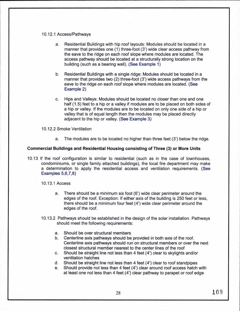
a. Residential Buildings with hip roof layouts: Modules should be located in a manner that provides one (1) three-foot (3') wide clear access pathway from the eave to the ridge on each roof slope where modules are located. The access pathway should be located at a structurally strong location on the building (such as a bearing wall). (See Example 1)
b. Residential Buildings with a single ridge: Modules should be located in a manner that provides two (2) three-foot (3') wide access pathways from the eave to the ridge on each roof slope where modules are located. (See Example 2) ·
c. Hips and Valleys: Modules should be located no closer than one and one half ( 1.5) feet to a hip or a valley if modules are to be placed on both sides of a hip or valley. If the modules are to be located on only one side of a hip or valley that is of equal length then the modules may be placed directly adjacent to the hip or valley. (See Example 3)
10.12.2 Smoke Ventilation
a. The modules are to be located no higher than three feet (3') below the ridge.
Commercial Buildings and Residential Housing consisting of Three (3) or More Units
10.13 If the roof configuration is similar to residential (such as in the case of townhouses, condominiums, or single family attached buildings), the local fire department may make a determination to apply the residential access and ventilation requirements. (See Examples 5,6,7,8)
10.13.1 Access
a. There should be a minimum six foot (6') wide clear perimeter around the edges of the roof. Exception: If either axis of the building is 250 feet or less, there should be a minimum four feet ( 4') wide clear perimeter around the edges of the roof.
10.13.2 Pathways should be established in the design of the solar installation. Pathways should meet the following requirements:
a. Should be over structural members b. Centerline axis pathways should be provided in both axis of the roof.
Centerline axis pathways should run on structural members or over the next closest structural member nearest to the center lines of the roof
c. Should be straight line not less than 4 feet (4') clear to skylights and/or ventilation hatches
d. Should be straight line not less than 4 feet (4') clear to roof standpipes e. Should provide not less than 4 feet ( 4') clear around roof access hatch with
at least one not less than 4 feet ( 4') clear pathway to parapet or roof edge
28 10 9

10.13.3 Smoke Ventilation
a. Arrays should be no greater than 150 by 150 feet in distance in either axis b. Ventilation options between array sections should be either:
1. A pathway 8 feet (8') or greater in width
2. 4 feet ( 4') or greater in width pathway and bordering on existing roof skylights or ventilation hatches
3. 4 feet ( 4') or greater in width pathway and bordering four feet ( 4') x 8 feet 8' "venting cutouts" every 20 feet (20') on alternating sides of the pathway
Location of Direct Current (DC) Conductors
10.14 Conduit, wiring systems, and raceways for photovoltaic circuits should be located as close as possible to the ridge or hip or valley and from the hip or valley as directly as possible to an outside wall to reduce trip hazards and maximize ventilation opportunities.
10.15 Conduit runs between sub arrays and to DC combiner boxes should use design guidelines that minimize total amount of conduit on the roof by taking the shortest path from the array to the DC combiner box. The DC combiner boxes are to be located such that conduit runs are minimized in the pathways between arrays.
10.16 To limit the hazard of cutting live conduit in venting operations, DC wiring should be run in metallic conduit or raceways when located within enclosed specs in a building and should be run, to the maximum extent possible, along the bottom of load-bearing members.
Non-Habitable Buildings
10.17 This guideline does not apply to non-habitable structures. Examples of non-habitable structures include, but are not limited to, parking shade structures, solar trellises, etc.
Ground Mounted Photovoltaic Arrays
10.18 Setback requirements do not apply to ground-mounted, freestanding photovoltaic arrays. A clear brush area of ten feet (10') is required for ground mounted photovoltaic arrays.
Examples of Photovoltaic Layouts
Example #1 Cross Gable Roof
29 110

EXA.\IPLE 1
Diagram 1: Cross Gable Roof
30 111

10.19 Example #2 Cross Gable with Valley
EXAMPLE2
Diagram 2: Cross Gable with Valley
10.20 Example #3 Full Gable
EXAMPLE 3
31 112

10.21 Example #4 Full Hip Roof
EXAMPLE 4
32 11.3

10.22 Example #5
EXA..\IPLE 5
----~-~·
(J) 0 ~
.. ,,... - l ·. ~
;.:o ~ l:· ' ;:u :..u ~
}> :i: '"0
I l -·
IJ~t~~ -
mtl : = o_
jT1
.--)> ::0 C') -....
0 ~
~ <: ,..., ::0 () 'i ~ a r-
\. f •
l B ~Kt
~L!!} Fill [ ~0~ l-1
: : ..
[.! j ~! 1..
l,!m i! ~ l HiiHtrlOO I
u rnn Uo ,'=~ ,o r .......... o'= Ill II [<\] , I
~J [,T !! 1Ci'
I li-t
I ~ \ r-,.
- ~
' .--1"1
33 114

10.23 Example #6
EXA.\IPLE 6
320
·~ ___ _.:::::.._
•
I ?: OJ ""0
X
.,.J
34 1.15

10.24 Example #7
EXA..'IPLE 7
~ l/} 0 4'
~ ~ ... ;o
!::3 " ~ ::: ::0 J,.. .;.o -< )> ~
::0
~ fl1
:r: ~ i: ~ s: ...., Ol -o s:
OJ r :::::!
,.: I r-1 r:
\ m I ,.,.,
l/} ~ I < :;:;: r1 r
r I z () lg G") 0 0 :s:. -o
M
0 () ::::0 ):>
c r .
0
Ul t 1\J
f < i 1'1 ::::0
I~ N u
r.• 3.
r 0
IOC' G
~ .-:E
35 116

~ Q)
a. E CIJ X w lO C\1 0 T""
00
~ a
v
200' ._ - - -
STRUCTUR,;L 1.1CM37 4' . 8 '
- - ----
! I ~Hmillf.tEJ.r~HfWJt§ -fUHfUi1Uillf-l~1lffiffifllftlil
l
§imffift~~mHU]ffiE ; ~nrnn~nr:niHHHnnninn~ I fftHHHff?·~ l ilffifffHHHHH . :t~·tiiffiffEHHfHHHHHHHH l
-,---I
STRUCT'JP.AL "'H'. I·~SI:.F _/
~OLAR ARRAY EX/'-.MPLE - SMALL COMMERCI.AL
8' WAU<WAYS
0 0 -
'-
!'.-! ...-!
\0 C"'"l


~_. FitW Palm Springs Very High Fire Hazard Severitv Zones in LRA
As Recommended b CA( FffiE
:::...---:---=~--.:::=.:
==-=-:-=-~=...::=:...:~
w~~~~
""-------------· ----~-------===-==::=.-:.=-::...-:::=-..:--·~ ·+