panasonic hy relays
DESCRIPTION
Panasonic HY RelaysTRANSCRIPT
HY
SPECIFICATIONS
TYPICAL APPLICATIONS
ORDERING INFORMATION
NON-POLARIZED 1 FORM C RELAY
HY RELAYS
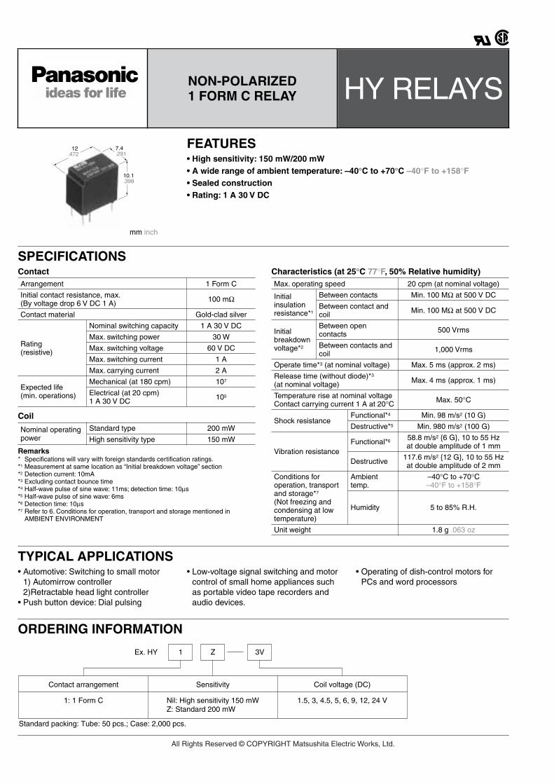
mm inch
7.4.291
10.1.398
12.472
FEATURES• High sensitivity: 150 mW/200 mW• A wide range of ambient temperature: –40°C to +70°C –40°F to +158°F• Sealed construction• Rating: 1 A 30 V DC
Contact
Coil
Remarks* Specifications will vary with foreign standards certification ratings.*1 Measurement at same location as “Initial breakdown voltage” section*2 Detection current: 10mA*3 Excluding contact bounce time*4 Half-wave pulse of sine wave: 11ms; detection time: 10µs*5 Half-wave pulse of sine wave: 6ms*6 Detection time: 10µs*7 Refer to 6. Conditions for operation, transport and storage mentioned in
AMBIENT ENVIRONMENT
Characteristics (at 25°C 77°F, 50% Relative humidity)Arrangement 1 Form C
Initial contact resistance, max. (By voltage drop 6 V DC 1 A) 100 mΩ
Contact material Gold-clad silver
Rating (resistive)
Nominal switching capacity 1 A 30 V DC
Max. switching power 30 W
Max. switching voltage 60 V DC
Max. switching current 1 A
Max. carrying current 2 A
Expected life (min. operations)
Mechanical (at 180 cpm) 107
Electrical (at 20 cpm) 1 A 30 V DC 105
Nominal operating power
Standard type 200 mW
High sensitivity type 150 mW
Max. operating speed 20 cpm (at nominal voltage)
Initial insulation resistance*1
Between contacts Min. 100 MΩ at 500 V DC
Between contact and coil Min. 100 MΩ at 500 V DC
Initial breakdown voltage*2
Between open contacts 500 Vrms
Between contacts and coil 1,000 Vrms
Operate time*3 (at nominal voltage) Max. 5 ms (approx. 2 ms)
Release time (without diode)*3
(at nominal voltage) Max. 4 ms (approx. 1 ms)
Temperature rise at nominal voltage Contact carrying current 1 A at 20°C Max. 50°C
Shock resistanceFunctional*4 Min. 98 m/s2 (10 G)
Destructive*5 Min. 980 m/s2 (100 G)
Vibration resistanceFunctional*6 58.8 m/s2 6 G, 10 to 55 Hz
at double amplitude of 1 mm
Destructive 117.6 m/s2 12 G, 10 to 55 Hz at double amplitude of 2 mm
Conditions for operation, transport and storage*7 (Not freezing and condensing at low temperature)
Ambient temp.
–40°C to +70°C –40°F to +158°F
Humidity 5 to 85% R.H.
Unit weight 1.8 g .063 oz
• Automotive: Switching to small motor1) Automirrow controller2)Retractable head light controller
• Push button device: Dial pulsing
• Low-voltage signal switching and motor control of small home appliances such as portable video tape recorders and audio devices.
• Operating of dish-control motors for PCs and word processors
1Ex. HY Z
Contact arrangement Sensitivity Coil voltage (DC)
Nil: High sensitivity 150 mWZ: Standard 200 mW
1: 1 Form C 1.5, 3, 4.5, 5, 6, 9, 12, 24 V
Standard packing: Tube: 50 pcs.; Case: 2,000 pcs.
3V
All Rights Reserved © COPYRIGHT Matsushita Electric Works, Ltd.

HY
TYPES AND COIL DATA (at 20
°
C 68
°
F)
200 mW Standard type
150 mW High sensitivity type
DIMENSIONS
mm inch
REFERENCE DATA
Part No. Nominal voltage, V DC
Pick-up voltage, V DC (max.)
Drop-out voltage,
V DC (min.)
Coil resistance,
Ω
(
±
10%)
Nominal operating
current, mA
Nominal operating power,
mW
Max. allowable voltage, V DC
(at 70
°
C 158
°
F)
HY1Z-1.5V 1.5 1.125 0.15 11.25 133.3 200 1.8
HY1Z-3V 3 2.25 0.3 45 66.7 200 3.6
HY1Z-4.5V 4.5 3.375 0.45 101.2 44.5 200 5.4
HY1Z-5V 5 3.75 0.5 125 40 200 6
HY1Z-6V 6 4.5 0.6 180 33.3 200 7.2
HY1Z-9V 9 6.75 0.9 405 22.2 200 10.8
HY1Z-12V 12 9 1.2 720 16.7 200 14.4
HY1Z-24V 24 18 2.4 2,880 8.3 200 28.8
Part No. Nominal voltage, V DC
Pick-up voltage, V DC (max.)
Drop-out voltage,
V DC (min.)
Coil resistance,
Ω
(
±
10%)
Nominal operating
current, mA
Nominal operating power,
mW
Max. allowable voltage, V DC
(at 70
°
C 158
°
F)
HY1-1.5V 1.5 1.125 0.15 15 100 150 2.1
HY1-3V 3 2.25 0.3 60 50 150 4.2
HY1-4.5V 4.5 3.375 0.45 135 33.3 150 6.3
HY1-5V 5 3.75 0.5 166 30.1 150 7
HY1-6V 6 4.5 0.6 240 25 150 8.4
HY1-9V 9 6.75 0.9 540 16.7 150 12.6
HY1-12V 12 9 1.2 960 12.5 150 16.8
HY1-24V 24 18 2.4 3,840 6.25 150 33.6
General tolerance: ±0.3 ±.012
3.5.138
0.5.020 5.08
.200
7.4.291
12.462
10.1.398
0.5.020
7.62.300 (0.82)
(.032)
0.4 dia..016 dia.
2.54.100
0.25.010
0.25.010
PC board pattern (Copper-side view)
Schematic (Bottom view)
Tolerance: ±0.1 ±.004
2.54.100
2.54.100
7.62.300
6-1 dia.6-.039 dia.
(0.82)(.032)
5.08.200
2.54.100
N.C.
N.O.
COM
1. Maximum switching power 2. Life curve 3. Mechanical lifeTested sample: HY1Z-12V, 10 pcs.Ambient temperature: 20°C to 25°C 68°F to 77°F
Contact voltage, V
Con
tact
cur
rent
, A
DC resistiveAC resistive
0.2
0.5
1.0
2.0
5.0
0.110 30 60 100 300
10
2030
50
100
200300
0.2 0.4 0.6 0.8 1.0 1.2 1.4Switching current, A
Life
, ×10
4
100 V AC resistive load
30 V DC resistive load
No. of operations, ×104
Rat
io a
gain
st th
e ra
ted
volta
ge, %
V
0
10
20
30
40
50
60
70
80
90
100
10 100 1,000 2,000
Min.
Max.
Min.
Max.
Drop-out voltage
Pick-up voltage
All Rights Reserved © COPYRIGHT Matsushita Electric Works, Ltd.
HY
NOTE
For Cautions for Use, see Relay Technical Information
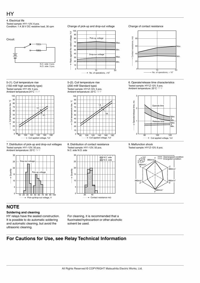
4. Electrical lifeTested sample: HY1-12V, 6 pcs.Condition: 1 A 30 V DC resistive load, 30 cpm
Circuit:
Change of pick-up and drop-out voltage Change of contact resistance
N.C. side: 3 pcs.N.O. side: 3 pcs.
0
10
20
30
40
50
60
70
80
90
100
Min.
Max.
Min.
Max.
10 20No. of operations, ×104
Drop-out voltage
Pick-up voltage
Rat
io a
gain
st th
e ra
ted
volta
ge, %
V
Con
tact
res
ista
nce,
mΩ
No. of operations, × 1042010
80
60
40
20
0
Min.
Max.
5-(1). Coil temperature rise (150 mW high sensitivity type)Tested sample: HY1-9V, 5 pcs.Ambient temperature:24°C 75°F
5-(2). Coil temperature rise (200 mW Standard type)Tested sample: HY1Z-12V, 5 pcs.Ambient temperature: 23°C 74°F
6. Operate/release time characteristicsTested sample: HY1Z-12V, 5 pcs.Ambient temperature: 25°C 77°F
0
10
20
30
40
50
60
70
80
90
100
80 100 120 140 160 180
0A
1A
Coil applied voltage, %V
Coi
l tem
pera
ture
ris
e, °
C
0
10
20
30
40
50
60
70
80
90
100
80 100 120 140 160 180
0A
1A
Coil applied voltage, %V
Coi
l tem
pera
ture
ris
e, °
C
Min.
Max.Min.
Max.
Coil applied voltage, %V
Ope
rate
/rel
ease
tim
e, m
s
Operate time
Release time
x
x
0
2
1
3
80 100 120
7. Distribution of pick-up and drop-out voltagesTested sample: HY1-12V, 50 pcs.Ambient temperature: 23°C 74°F
8. Distribution of contact resistanceTested sample: HY1-12V, 50 pcs.N.C. side N.O. side
9. Malfunction shockTested sample: HY1Z-12V, 6 pcs.
0
5
10
15
20
25
30
10 20 30 40 50 60 70 80 90 100
Qua
ntity
Pick-up/drop-out voltage, V
Drop-out voltage
Pick-up voltage
0
5
10
15
20
25
30
30 40
N.C. sideN.O. side
Contact resistance mΩ
Qua
ntity
Y’
X Z
Z’ X’
980m/s2
980m/s2
980m/s2
980m/s2 980m/s2
980m/s2
X’XZ’
YY’
Z Y Deenergized conditionEnergized condition
Soldering and cleaningHY relays have the sealed construction.It is possible to do automatic soldering and automatic cleaning, but avoid the ultrasonic cleaning.
For cleaning, it is recommended that a fluorinated hydrocarbon or other alcoholic solvent be used.
All Rights Reserved © COPYRIGHT Matsushita Electric Works, Ltd.