panchsheel fasteners p. ltd.hsfg bolts and nuts. the information presented herein was put together...
TRANSCRIPT
PANCHSHEEL FASTENERS P. LTD.
The purpose of this Field Manual for Structural Bolting is to summarize basic definitions, concepts and procedures for bolted connections. This Manual addresses general
considerations for bolting, installation preparation, installation techniques and inspection and testing procedures.
This manual is to assist engineers, inspectors and construction workers to install and inspect bolted connections to meet current specifications. It also addresses the system of testing the HSFG bolts and Nuts.
The information presented herein was put together by the technical team of
Panchsheel Fasteners. The contents are taken from several sources including text books, related standards EN, ASTM, IS, published articles, research papers, the
Specifications for Structural Steel Joints using High Strength Steel Bolts by the
Research Council on Structural Connection, (RCSC) and our long experience in this field.
The primary function of bolted connections is to join the structural members and safely
transmit loads from one member to the other. As such, bolted connections are critical components of any structure. For many types of structural systems, failure of a bolted connection could lead to collapse or extensive system-wide damage. Therefore, current
design specifications and construction procedures impose rigorous installation and inspection practices to ensure that such connections are able to perform their function safely.
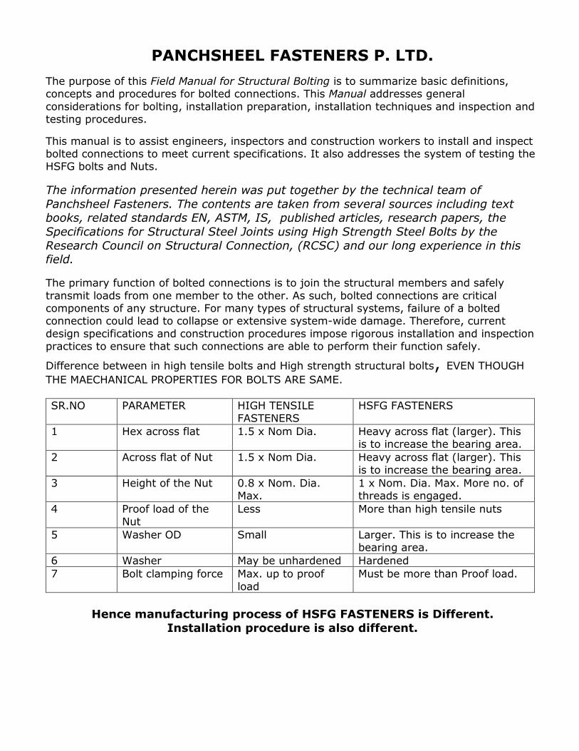
Difference between in high tensile bolts and High strength structural bolts, EVEN THOUGH
THE MAECHANICAL PROPERTIES FOR BOLTS ARE SAME.
SR.NO PARAMETER HIGH TENSILE FASTENERS
HSFG FASTENERS
1 Hex across flat 1.5 x Nom Dia. Heavy across flat (larger). This is to increase the bearing area.
2 Across flat of Nut 1.5 x Nom Dia. Heavy across flat (larger). This is to increase the bearing area.
3 Height of the Nut 0.8 x Nom. Dia. Max.
1 x Nom. Dia. Max. More no. of threads is engaged.
4 Proof load of the Nut
Less More than high tensile nuts
5 Washer OD Small Larger. This is to increase the bearing area.
6 Washer May be unhardened Hardened
7 Bolt clamping force Max. up to proof
load
Must be more than Proof load.
Hence manufacturing process of HSFG FASTENERS is Different.
Installation procedure is also different.

EQUIVALENT SPECIFICATIONS
IS TITLE ASTM
3757 Specifications for High Strength structural bolts (grade 8.8 and 10.9)
A 325 for grade 8.8 and A 490 for grade
10.9 or ASTM A3125-15
6623 Specifications for high strength structural nuts A 563
6649 Specifications for the high strength structural
washers (hardened)
F 436
1367-3 Mechanical properties of the externally threaded
fasteners
A 370, F 606-14
1367-6 Mechanical properties of the nuts A 370, F 606-14
NORMALLY APPLICABLE EN 14399 SPECIFICATIONS
14399-2 Bolt preloading suitability test
14399-3 HR system, grade 8.8 or 10.9, thread length varies with the length of the bolt, nut height 0.9 x nom. Dia. max.
14399-4 HV system grade 10.9, Fixed thread length, nut height 0.8 x nom. Dia. max.
14399-5 & 6 Plain washer & plain chamfered washer
14399-9 DTI washers for HR & HV system
ISO 898-1 Mechanical properties of externally threaded fasteners
ISO 898-2 Mechanical properties of the nut
HANDLING AND STORAGE
It is “PANCHSHEEL FASTENER’s” standard practice that the Bolts, nuts, and washers are buttoned (assembled) as per size and are packed size wise.
By default our products are zinc phosphate coated and oiled then packed in polythene bag. This is to protect the products from atmospheric corrosion. Normally the each packaging weighs between 25/30 Kgs each.
CONE OF CLAMPING FORCE IS LARGER DUE TO HIGHER ACROSS FLATS OF BOLT AND NUT, LARGE DIAMETER OF THE HARDENED WASHER. THIS HOLDS THE PLIES TOGETHER & SHEAR FORCES ARE RESISTED BY THE FRICTION BETWEEN TWO PLIES AND NOT THROUGH THE BOLT.
SO BOLT IS KNOWN AS “HIGH STRENGTH FRICTION GRIP BOLT”.

Fasteners must be protected from dirt and moisture. Only the number of fasteners required to be installed and tightened during a working shift should be removed from storage. Unused fasteners should be returned to protected storage at the end of a shift. Lubricant should not
be removed.
PRODUCTS NOT STORED PROPERLY
PRODUCTS ARE STORED PROPERLY. GUNNY BAGS ARE KEPT ON WOODEN PALLET AND NOT TOUCHING TO GROUND.
STANDARD PACKING SYSTEM OF PANCHSHEEL FASTENERS. EXTERNAL JUTE BAG (Protects from external damages, provides strength)
INTERNAL POLYTHENE BAG (protects the product from dust & moisture and atmospheric corrosion attack)
OILED AND BUTTONED (Bolt + Nut+ Washer assembled) PRODUCTS. Oil protects from rusting and provides lubrication)

FEW DEFINITIONS AND CONCEPTS
GRIP LENGTH: The combined thickness of all components joined together between the bolt
head and nut. (See above) NUT FACTOR (K): An empirically determined constant that covers many variables such as
friction, which affects the torque tension relationship. The recommended values for “K” are as below: (Source Industrial Fasteners Institute)
1. Dry un lubricated – 0.30
2. Zinc electroplated---0.20 3. Hot dip Galvanized---0.15
4. Cadmium plated --- 0.16 5. Lubricated by oil --- 0.15 to 0.18 6. Xylan coating --- 0.12
7. Dacro coating --- 0.13
TORQUE: The energy taken to rotate the nut on the bolt thread. It is measured in N.Mt. Torque (T)N.Mt. = Nut factor “K” x Clamping force F1 (N) x Nominal diameter of bolts (Mt)
BOLT TENSION: The force generated in the bolt due to tightening, this holds the plies together. It is also known as clamping force or preload. It is measured in KN.
Where At= Area at threaded section shall vary as per nominal diameter, Sp= Proof stress
shall vary as per the grade. (Refer IS -1367-3 for these values) EMBEDMENT: Localized yielding of bolted joint components resulting in change of grip
length hence causing “RELAXATION” of the bolted joint. FAYING SURFACE: The plane of contact between two plies of a joint. COATED FAYING SURFACE: A faying surface that has been primed, primed and painted, or
protected against corrosion. FIRM CONTACT: The condition that exists on a faying surface when the plies are solidly
seated against each other. CONNECTION: An assembly of one or more joints that is used to transmit forces between two or more members.
JOINT: A bolted assembly that is used to join two or more structural elements. PRE TENSIONED JOINT: A joint that transmits shear and/or tensile loads in which the bolts
have been installed. SHEAR/BEARING JOINT:A snug tightened joint or pre-tensioned joint with bolts that transmit shear loads and for which the design criteria are based upon the shear strength of
the bolts and the bearing strength of the connected materials. SLIP CRITICAL JOINT: A joint that transmits shear loads or shear loads in combination
with tensile loads in which the bolts have been installed and with faying surfaces that have been prepared to provide resistance against slip. TENSION CALIBRATOR: A calibrated tension-indicating device that is used to verify the
acceptability of the pre-tensioning method. It is the device for developing torque-tension relationships. It should be calibrated annually by a certified lab. SKIDMORE clamping force
measuring machine is most popular. DIRECT TENSION INDICATOR: Direct tension indicators (DTIs) are special washers with
raised protrusions on one face, which compress when the bolt is tightened. They are used for verifying proper tensioning without relying on turn of the nut markings.

SNUG THIGHT: Snug tight condition is defined as the full effort of a typical person as applied using an ordinary spud wrench. A bolt in snug tight condition will develop approximately 10% of its pretension load.
TURN OF NUT: A technique for ensuring that the minimum pre-tensioning has been achieved. Turn-of-nut pre-tensioning involves holding one end of the bolt assembly (head or
nut to protect from unwanted rotation) and rotating the other end to achieve a specified rotation, which varies by bolt diameter and length.
VERIFICATION TESTING: Prior to fastener installation, representative samples of bolt assemblies must be checked in a device that indicates bolt tension.
Bolt Holes
There are four types of holes: standard (STD), oversize (OVS), short Slot (SSL) and long Slot
(LSL) see Figure below. Unless otherwise specified, only STD holes should be used.
Burrs those which prevent solid seating of connected parts in the snug tight condition must be removed by reaming or light grinding. Note that recoating is required after grinding.
RECOMMENDED HSFG BOLT INSTALLATION PROCEDURE
1. Bring the steel sections to be joined together and align the holes with drift pins
as seen in the picture.
2. Bolts should not be used as drift pins to achieve alignment; this could result in
thread damage.
3. Fill the remaining the holes with HSFG BOLT & DTI Assemblies of the correct size.
4. Partially tension the assemblies to snug the connection, this is achieved when the steel sections are in contact and the protrusions of the DTIs are just
starting to be deformed.

5. At this point there will be approximately 50% of the minimum specified bolt
preload applied.(Refer our catalogue for these suggested torque values) 6. Unwanted rotation of bolt head or nut should be arrested by using spanners or
any suitable means 7. You may use pneumatic, hydraulic, electric or manual operated torque wrench.
HSFG BOLT TIGHTENING PROCEDURE
Generally two methods are most popular. First is “TURN OF NUT” method and second is use of DTI WASHER”.
TURN OF NUT Installation beyond snug- tight is called pre-tensioning. Prior to fastener installation, a representative sample of not less than three bolt, nut and washer assemblies of each
diameter and bolt length specified must be checked in a device that indicates bolt tension. The device may be electronic or hydraulic.
These tests should demonstrate that controlling the required turns from a snug tight condition develops a tension no less than 5% greater than the required tension. This is known as “bolt verification testing”.
Turn-of-nut pre-tensioning involves the following steps: 1. Ensure the bolt is in snug tight condition.
2. Match mark is placed on each nut, bolt and steel surface in straight line. 3. Unwanted rotation is to be prevented by using spanner or any suitable means. 4. The bolt is tightened with prescribed rotation after snug tight condition.
Look at the bolt stick-out. “Stick out” is the amount the bolt extends beyond the outside surface of the nut. Positive stick-out is acceptable (Min. One complete thread
after tightening the nut) but negative stick out is NOT acceptable (the end of the bolt should NOT be inside the nut)
SEE THE PICTURE BELOW SHOWN FOR ½ TURNING OF NUT.

AS THE HSFG BOLTS ARE TIGHTENED ABOVE TH PROOF LOAD, BOLT MAY GET SLIGHTLY ELONGATED. THIS IS PERMANENT ELONGATION. HENCE HSFG BOLT
CANNOT BE REUSED. SEE ABOVE.
USE OF DTI WASHER
Tightening of HSFG bolt is critical. We must ensure that sufficient “clamping force” is generated and two components of the joint are firmly held.
Correctly what we expect is Accuracy in measurement, Consistency and reliability, ease of installation, less involvement of skilled persons, ease of inspection, standardization and cost effective. The simplest, installation and inspection efficient solution is use of DTI washer.
A study shows that 35% time is saved as compared to Turn of nut method.
DTI washer is especially hardened washer with protrusions on one face. The protrusions
create the gap. As the bolt is tightened, clamping force is generated. The DTI washer also experiences this force, resulting in collapse of the arch like protrusions. This reduces the gap.
The gap is verified with help of feeler gauge. This deformation is co related to the bolt tension.
DTI acts as weighing scale and measures the bolt tension developed in each bolt.
DTI is placed under the bolt head or between the plate and bearing face of the nut. Ensure in NO case the bumps should get rubbed during the tightening process.

POSITION OF THE DTI WASHER WHEN NUT IS ROTATED (ABOVE)
POSITION OF THE DTI WASHER WHEN BOLT HEAD IS ROTATED (ABOVE)
Tighten all the bolts with hand wrench. Apply torque to all bolts in the pattern using a criss-cross sequence. When turning the opposite nut or bolt head, prevent the unwanted rotation
of opposite end as this rotation can wear down the bumps. You may use spanner or any suitable means to prevent such rotation. This criss-cross sequence should be performed using a series of passes at a torque value that
is a fraction of the target torque and increases for each pass. For example: if the target torque is 300 NM, the first pass might be 30% of the target
torque, which would be 90 NM, the second pass might be 70% or 210 NM, and so on. The number of passes performed in this manner will depend on the application and site conditions.
A final criss-cross sequence will be performed using the following procedure.

Tighten bolt number 1 by slowly applying torque until the desired gap is achieved in half or
more of the entry spaces. Repeat this process for bolts 2 &3. Check the gap with GO and NOGO feeler gauge. Record the amount of torque required for each bolt and computes an average torque value.
Use the average torque value to tighten the remaining bolts in the flange using the criss-cross sequence. Make a final circular pass using the average torque value.
Check the gap for each bolt in the circular pattern using the procedure described in the INSPECTION section of this manual. If the No-Go gauge is not refused in half or more of the entry spaces, apply a greater amount
of torque to the nut until the No-Go gauge is refused in half or more of the entry spaces.
REMEMBER ACIEVING THE CLAMPING FORCE IS IMPORTANT.TORQUE MAY VARY.
DTI WILL INDICATE THAT THE DESIRED CLAMPING FORCE IS DEVELOPED OR NOT.TAKE ACTION AS PER SIGNALS GIVEN BY THE DTI WASHER.
In the rare instance it may happen that the No-Go gauge is refused and the Go gauge (0.1 mm) is also refused. As per our standard 0.1 mm feeler gauge passing at one location indicates that there is “NO ZERO GAP” hence ACCEPTABLE. In group of tightened bolts,
max. 10% bolts may show NON ACCEPTANCE of 0.1 mm feeler gauge. This is NOT a point of rejection.
In case it exceeds more than 10% then we need to replace the bolt and DTI washer.
To avoid such situations it is recommended to tighten the bolts in few
passes or steps as described above.
DTI TESTING (REF. ASTM F 959 or EN 14399-9)
This test method is for the measurement of compressive loads developed with direct tension indicators. The method involves a pressing/flattening operation to remove variations due to
the manufacturing process, which is followed by measurement of the compression load when the protrusions are deformed to the specified gap.
Testing apparatus shall include a compression loading system, top and bottom bearing blocks, and support blocks that allow each direct tension indicator to be measured using a direct reading gauge.

Because of acceptable variations in bolt dimensions, geometrical tolerences and coating characteristics, bolts cannot be used as a means of gauging the direct tension indicator measured minimum and maximum performance.
TESTING OF HSFG BOLTS & NUTS
Every product inspection and testing involves specific “INSPECTION AND TESTING
ACCESSORIES”. Many cases we have experienced that the products are tested without such accessories and nonstandard testing practices are adopted. So many times GOOD product is
rejected or BAD product is accepted.
Hence we have prepared few guidelines for testing of the HSFG bolts and nuts. These
guidelines are made in line with the applicable standards. One can refer the applicable standards for further details.
BOLT TESTING (IS -1367-3)
Sample preparation for tensile testing is critical. While machining the GAUGE diameter, we should NOT reduce the nominal diameter of the bolt more than 25%. So if we are testing M
30 bolt then our minimum gauge diameter shall be 23 mm, The gauge length shall be 115 mm. Considering the length required for gripping during the testing, we need the product minimum length as 175 mm. The products having the lengths less than 175 mm shall be
tested for WEDGE LOAD & PROOF LOAD. The products having too small sizes and cannot be WEDGE & PROOF load tested are to be checked on hardness basis.
The location of the test piece is at the center. See below.

Selection of the GAUGE DIAMETER should be done as stated in ISO 6892-1 standard.
To evaluate yield stress we MUST have EXTENSOMETER. This may be manual or electronic version.
To grip the specimen in the machine you need to have ADOPTORS top and bottom as seen below. You also need the THREADED mandrels or washers to grip the threaded end. You
should have such threaded washers or mandrels suitable for M 12 to M 36. These mandrels/ washers are made of alloy steel and MUST be hardened and tempered to 40/45 HRC.
For wedge load testing and Proof load testing the length of the bolt MUST BE minimum 4 x Nominal diameter of the bolt. So for M 24 bolt minimum length of the
bolt for wedge load or proof load test is 96 mm. The products smaller than minimum length should be accepted on basis of hardness and other tests.

For wedge load testing we need to have the TAPERED HARDENED WASHERS. Dimensions are specified in IS 1367-3 standard.
Proof load testing involves precision measuring system. You should have a dial gauge having
1 micron least count. The samples are drilled on head as well as on the threaded end. We should precisely measure the length of the product at the drilled hole. After applying the load
we need to re-measure the length at same location. The difference in two measurements shall NOT over ± 12.5 microns.
Specimen holders for machined tensile test specimen, wedge load and proof load test of the bolts
Threaded washer / mandrel suitable for every nominal diameter of the bolt, is required for proof and wedge load test and for machined tensile test specimen. Min. thickness of the washer should be equal to nominal diameter of the bolt. Minimum 4 treads should be exposed between thread run out and top face of threaded washer.
Plain hardened washers suitable for every nominal diameter of the bolts. The same washer can be used for proof load testing. The hole size shall be as per ISO273 medium series.
You need to have these taper hardened washers for each nominal diameter.

DE- CARBIZING TEST Decarburization is to be checked by microscopic method and hardness test method. Microscopic method is to be used for checking the complete “DECARB”. In any grade
maximum permissible value is 15 microns. Partial decarb is to be checked on MICRO HARDNESS TESTER with 300 gms load. This is decisive method.
Measurement of bolt length prior to loading and after applying PROOF LOAD. Difference in two readings shall not exceed ±12.5 microns. Proof Load values are specified in IS 1367-3 standard.

SURFACE INTIGRITY To do this test you need Magnetic Particle Inspection (MPI) machine. Machine and black light
should be calibrated. Your operator MUST be having VALID ISNT/ASNT NDT certificate and EYE fitness certificate to conduct the test. IS 1367-9 sec 1 and 2 are to be referred for
acceptance criteria.
PROOF LOAD TESTING OF THE NUT (REF. IS 1367-6)
To conduct the proof load testing of the nut we need to have the threaded mandrel or hardened washer as shown in the standard. (See below) The tolerance class of the threads of
mandrel should be “5h6g” and hardness should be 45 HRC min. We can test either in by applying tensile force or by applying compressive force, but TENSILE TEST is decisive.

PROBLEMS COMMONLY ENCOUNTERED WHEN TIGHTENING BOLTS
Dry or Rusty Threads: Usually caused by poor storage conditions, dry or rusty bolts and nuts should not be permitted. Ideally - nuts, bolts, washers and DTIs should be kept in dry storage and their containers be opened just before use.
Rust significantly increases the amount of torque required to tension a bolt.
Damaged Threads: Usually caused by forcing the bolt through misaligned holes, poor handling - this will cause the nut to freeze. Use drift pins for aligning the holes, handle
externally threaded products carefully.

Thread stripping:
The main reason is incorrect pitch of the bolt or nut, Poor strength in the threads or excess
clearance in bolt and nut threads, excess torqueing. If the nut material is stronger than the bolt material then bolt threads will shear. The failure
will occur at the root of the bolt threads. If the bolt material is stronger than the nut material then nut threads will shear. The failure will occur at the root of the nut threads.
The nut and bolt are the same strength, both threads will strip simultaneously. This failure will occur at the pitch line.
Tensile failure of the bolts:
This tensile failure occurs at the thread run out; being this is the weakest section. This failure
may occur at the minor diameter of the threads. Elongation is observed in the threads.
Wrong pitch, threads of poor strength and over size nuts lead to thread stripping. Thread stripping of bolt or nut depends on which part has more strength.

Bolt failure due to excess torqueing:
Trapped Bolts: Usually caused by slippage in the joint as a result of flanges slip- ping out of alignment after the bolts have been installed.. Securing the flanges by partially loading four or more bolts after careful alignment should prevent this problem.
Hardened Washers under the Turned Element: The use of hardened washers under the turned element significantly reduces the torque required to tension a bolt.
Hardened Washers under the DTI: When the surface of the flange making con- tact with
the DTI is rough or uneven, place a hardened 1/4” thick washer under the DTI. This will ensure accurate measurement of the gap between the DTI and the nut.
CONCLUSION 1. Stored the fasteners properly.
2. Document the bolt tightening procedure. Apply the torque in steps. 3. Pre installation verification of 3 bolts is to be done EVERYDAY, it is essential. 4. DTI calibration is to be done as stated in EN 14399 -9 standards.
5. Check with the testing lab as they have adequate testing accessories for checking the bolts and nuts.
6. Check QAP for testing and acceptance of the products those are too small for testing. 7. In case of any doubt or clarification required then please contact “PANCHSHEEL
FASTENERS”.
xxxxxxx