panduit termination solutions - digi-key sheets/panduit pdfs/catalog... · or visit . panduit...
TRANSCRIPT

Terminals
A1For service and technical support, call 800-777-3300
or visit www.panduit.com.
PANDUIT Termination Solutions
SuccessDepends on theCrimp.
A proper crimp is the key elementof an overall wire terminationassembly that unfortunately is alltoo often overlooked.
Proper terminal selection, application and crimping are critical factors tothe safety, performance and reliability of an electrical connection.Whenselected and installed properly, the function of a terminal is transparentin the overall operation of a product; however, when selected or installedimproperly, it can result in rework, recalls and downtime, which couldresult in loss of productivity and profitability.
To produce a high-quality crimp you can rely upon to resist failure, youneed the right terminal, right tool and right technique.
The purpose of the Technical Reference Guide is to give you thenecessary tools to:
• Select the right terminal for a specific application• Select the right tool for the terminal and the application• Produce a high-quality crimp

Term
inal
s
A2
Crimping Guidelines for PANDUIT ® PAN-TERM®
Terminals, Disconnects, Splices and Wire Joints
1. Select the proper PANDUIT terminal for the application andwire size used• Ring terminals are used
for high vibration andgrounding applications
• Fork terminals are used for static(non-vibration) applications
• Disconnects are used forapplications that require quickconnection of wires without the use of tools
• Splices and wire joints are used to join wires together
• PANDUIT productpackaging label
• Packaginginstructionsincluded with thePANDUIT product
• Or if no packaginginstructions areavailable, plan your strip length so that 1/32 of an inch ofwire can be seen protruding through the tongue end ofthe terminal barrel
2. Strip wire to the proper length as specified on:
• Use crimping tools that provide a UL Listed and/or CSACertified electrical termination, to assure a safe andreliable connection
• PANDUIT terminals are UL Listed and CSA Certified whencrimped with PANDUIT plier type crimping tool or with thepreferred CONTOUR CRIMP™ Controlled Cycle Crimping Toolspecified on the packaging label
3. Select the proper crimp tool to be used
Plier TypeCrimping Tool
CONTOUR CRIMP ™
Controlled CycleCrimping Tool

Terminals
A3For service and technical support, call 800-777-3300
or visit www.panduit.com.
Crimping Guidelines for PANDUIT ® PAN-TERM®
Terminals, Disconnects, Splices and Wire Joints(continued)
Insulated Terminals and Disconnects
4. Select the proper crimp pocket for the terminals and wiresize you are using• PANDUIT crimping tools simplify this process with color
coded crimp pockets. The yellow, blue and red pocketsare specifically designed for the industry standard barrelsizes, each with a specific color code.
A. Locate terminal in appropriate size color-coded crimp die pocketwith tool centered on insulation sleeve. (See Note 1 page A6)
B. Rotate terminal so tongue is level with crimp die.
C. Insert properly stripped wire into terminal until a minimum of1/32" of wire extends beyond the terminal barrel.
D. Squeeze tool handles firmly to perform the electrical crimp.(See Note 2 page A6)
E. Provide second crimp on the flared portion of the insulationhousing to close the insulation as shown. Caution: when usingplier type crimping tools, do not squeeze as firmly as you didfor the electrical crimp. (See Note 3 page A6)
Step A Step B
Complete Crimp
Steps C & D
Step E
5. Perform the electrical crimpFor the plier type tool

Term
inal
s
A4
Crimping Guidelines for PANDUIT ® PAN-TERM®
Terminals, Disconnects, Splices and Wire Joints(continued)
Non-Insulated Terminals and Disconnects
Insulated and Non-Insulated Parallel Splices
A. Locate terminal in appropriate wire gauge crimp die pocketwith indenter centered on barrel seam.
B. Rotate terminal so tongue is level with crimp die.
C. Insert properly stripped wire (based on recommendations onpackage label) into terminal until a minimum of 1/32" of wireextends beyond the terminal barrel.
D. Squeeze tool handles firmly to perform the electrical crimp.(See Note 2 page A6)
Step A Step B Steps C & D
Complete Crimp
A. Locate parallel splice in appropriate wire gauge crimping diepocket and position tool on the center of the splice.
B. Insert properly stripped wire (based on recommendationson package label) into each end of the parallel splice.
C. Squeeze tool handles firmly. (See Note 2 page A6)
D. An insulation crimp is not required on an insulatedparallel splice.
Steps A & B Steps C & D Complete Crimp

Terminals
A5For service and technical support, call 800-777-3300
or visit www.panduit.com.
Insulated and Non-Insulated Butt Splices
Crimping Guidelines for PANDUIT ® PAN-TERM®
Terminals, Disconnects, Splices and Wire Joints(continued)
A. Locate butt splice in appropriate color-coded crimp die pocketand position crimp halfway between the wire stop (centerof splice) and the end of the insulation crimp area. (SeeNote 4 page A6)
B. Insert properly stripped wire (based on recommendations onpackage label) into one end of butt splice.
C. Squeeze tool handles firmly to perform the electrical crimp.(See Note 2 page A6)
D. Provide second crimp on the flared portion of the insulationhousing to close the insulation. Caution: When using pliertype crimping tools, do not squeeze as firmly as you did forthe electrical crimp. (See Note 3 page A6)
E. Repeat steps one to four for opposite end of butt splice.
Steps A & B Steps C
Complete Crimp
Step D & E

Term
inal
s
A6
Insulated and Non-Insulated Wire Joints
NOTES for Crimping with the preferred Hand OperatedControlled Cycle Crimping Tools:
A. Properly strip wires per manufacturer’s recommendationson product package label.
B. Twist stripped wire ends together, and insert wires intowire joint.
C. Locate wire joint in appropriate wire gauge crimp die pocketand position crimp in the center of the metal insert.
D. Squeeze tool handles firmly to perform the electrical crimp.(See Note 2 below)
Note: an insulation crimp is not required on an insulatedwire joint.
Steps 1 & 2 Steps 3 & 4 Complete Crimp
1. PANDUIT controlled cycle crimping tools properly locate rings, forks,and barrel insulated disconnects, pins, and blades. No furtherpositioning is required.
2. When using the preferred controlled cycle tool, once a crimp has beenstarted, the ratchet device of controlled cycle tools will not release untilthe crimp is complete, independent of operator expertise.
3. Controlled cycle tools provide the electrical crimp and the insulationclosure in a single cycle of the tool.
4. When using controlled cycle tooling, insulated butt splices must beinserted from the back of the tool to ensure that the electrical andinsulation closure crimp pockets are properly aligned with the splice.
Crimping Guidelines for PANDUIT ® PAN-TERM®
Terminals, Disconnects, Splices and Wire Joints(continued)

Terminals
A7For service and technical support, call 800-777-3300
or visit www.panduit.com.
Bent Back Strands Over Crimp Rotated Crimp
Crimping Guidelines for PANDUIT ® PAN-TERM®
Terminals, Disconnects, Splices and Wire Joints(continued)
A. Make sure the terminal barrel is centered correctly in theright die pocket by using the product locator on the backsideof the tool.
B. Determine the correct die pocket to use based on the colorcode of the terminal.
C. Squeeze the handles of the tool until one click is heard; thisclick indicates the terminal is now held in place securely toinsert the wire.
D. Insert the wire and complete cycle to perform the electricaland insulation crimp simultaneously.
E. Crimp complete.
Note: If your crimp looks like any of the examples shown below,cut off the terminal and recrimp. These crimps wouldprovide a poor connection!
5. Perform the electrical crimpusing the preferred controlled cycle tool
6. Inspect the crimp
Step A Step B
Complete Crimp
Step C
Step D

Terminal Series
Std.Wire
Range(AWG)
WireStrip
Length(In.)
[+1/32;-0]
Plier Tools Controlled Cycle Hand Tools
Crimp Headsfor Pneumatic
CT-600 Tool
Butt SplicesBS – Non-Insulated Butt Splices 26-22 1/4 X X
22-18 9/32 X X X X X X16-14 9/32 X X X X X X12-10 9/32 X X X X X X X
BSH – Heat Shrink 22-18 5/16 X16-14 5/16 X12-10 5/16 X
BSN – Nylon Insulated 26-22 1/4 X X X22-18 9/32 X X X X X X16-14 9/32 X X X X X X X X12-10 9/32 X X X X X X X
BSV – Vinyl Insulated 22-18 5/16 X X X X X X X X16-14 5/16 X X X X X X X X X12-10 5/16 X X X X X X X
DisconnectsD, DR – Non-Insulated, Sleeve Barrel(Includes Right Angle)
22-18 9/32 X X X X X16-14 9/32 X X X X X X12-10 9/32 X X X X X X X
TerminalsA8 PANDUIT
Installation Tooling for Terminals,
Disconnects and Splices
CT-
100
CT-
160
CT-
200
CT-
260
CT-
300-
1
CT-
310
CT-
400
CT-
460
CT-
1014
CT-
1015
CT-
1525
CT-
1550
CT-
1551
CT-
1570
CT-
1701
CT-
500C
H
CT-
520C
H
CT-
550C
H
CT-
570C
H
CT-
720
Mec
hani
cal

Terminals
A9
For service and technical support, call 800-777-3300
or visit ww
w.panduit.com
.
PANDUITInstallation Tooling for Term
inals,Disconnects and Splices (continued)
D-M – Non-Insulated Male BladeAdapters
22-18 9/32 X X X X X X16-14 9/32 X X X X X X
D-M – Non-Insulated Male 12-10 9/32 X X X X X XD-MB, DR-B – Non-Insulated RightAngle Female & Non-Insulated MaleButted Seam
22-18 9/32 X X X X
16-14 9/32 X X X XDNF – Nylon, Funnel Entry, BarrelInsulated (not .110/.111)
22-18 9/32 X X X X16-14 9/32 X X X X X X X X
DNF-110, DNF-111 – Nylon, FunnelEntry Barrel Insulated .110/.111 Tab Size
22-18 7/32 X X X X16-14 9/32 X X X
DNF-FI – Nylon, Fully Insulated 22-18 9/32 X X X X X X X X16-14 9/32 X X X X X X X12-10 3/8 X X X X X X X
DPF-FI – Premium Nylon, Fully Insulated 12-10 3/8 X X X X X X XDNF-FIB, DNF-FIM, DNF-FIMB,DPF-FIB, DPF-FIMB, DNF-LPB,DPF-LPB – Nylon & Premium GradeNylon, Fully Insulated, Funnel Entry,Male/Female Couplers (not .110/.111)
22-18 9/32 X X X
16-14 9/32 X X X
12-10 3/8 X
DMF-FIB, DPF-FIB – Nylon PremiumGrade Nylon, Fully Insulated, FunnelEntry, .110/.111 Tab Size
22-18 7/32 X X X
DNF-FIBX – Nylon, Expanded WireEntry, Fully Insulated
22-18 9/32 X16-14 9/32 X
DNF-M – Nylon Insulated, FunnelEntry, Barrel Insulated, Male
22-18 9/32 X X X X X X X16-14 9/32 X X X X X X X12-10 9/32 X X X X X

Terminal Series
Std.Wire
Range(AWG)
WireStrip
Length(In.)
+1/32;-0]
Plier Tools Controlled Cycle Hand Tools
Crimp Headsfor Pneumatic
CT-600 Tool
DNFR-B – Nylon Pre-Insulated,Right Angle
22-18 9/32 X X16-14 9/32 X X
DNFR-FIB – Nylon Butted Seam,Right Angle
22-18 11/32 X16-14 11/32 X
DNG-FB – Supra Grip Nylon FullyInsulated (Except DNG14-187FB &DNG14-188FB)
22-18 1/4 X
16-14 1/4 X
DNG-FL – Disco-Lok Nylon, FullyInsulated
22-18 1/4 X16-14 1/4 X
DNH – Heat Shrink 22-18 5/16 X16-14 5/16 X12-10 5/16 X
DV – Vinyl Barrel Insulated Sleeve 12-10 9/32 X X X XDV-B – Vinyl Insulated, Butted Seam 22-18 1/4 X X X
16-14 1/4 X X XDV-M – Non-Insulated Male BladeAdapters
22-18 9/32 X X X X X X X X16-14 9/32 X X X X X X X X X
DV-M – Non-Insulated MaleDisconnects 12-10 9/32 X X X
TerminalsA10
CT-
100
CT-
160
CT-
200
CT-
260
CT-
300-
1
CT-
310
CT-
400
CT-
460
CT-
1014
CT-
1015
CT-
1525
CT-
1550
CT-
1551
CT-
1570
CT-
1701
CT-
500C
H
CT-
520C
H
CT-
550C
H
CT-
570C
H
CT-
720
Mec
hani
cal
PANDUITInstallation Tooling for Term
inals,Disconnects and Splices (continued)

Terminals
A11
For service and technical support, call 800-777-3300
or visit ww
w.panduit.com
.
PANDUITInstallation Tooling for Term
inals,Disconnects and Splices (continued)
DV-MB – Vinyl Insulated Butted SeamMale Disconnects
22-18 9/32 X X X X X16-14 9/32 X X X X X X
DV-P – Vinyl Insulated PiggybackDisconnects
22-18 1/4 X X X X X X X16-14 1/4 X X X X X X X
DVF – Vinyl Funnel Entry BarrelInsulated Female Disconnect
22-18 9/32 X X X X16-14 9/32 X X X X
Wire Joints
J – Non-Insulated J214-312,J318-412,J216-410
18-12 1/2 X X18-12 1/2 X X16-10 3/4 X
JN – Nylon Insulated JN224-318,JN218-216,JN418-212,JN314-212
24-16 7/16 X X X X X X X X22-14 7/16 X X X X X X X18-12 1/2 X X X X X X14-12 5/8 X
Terminals
P-HDR – Non-Insulated HeavyDuty Rings 16-12 9/32 X X X X X X X
P-P – Non-Insulated Pin Terminals 22-18 9/32 X X X X X X16-14 9/32 X X X X X X12-10 9/32 X X X X X X X
P-R – Non-Insulated Large RingTerminals
8 3/8 X6 7/16 X4 1/2 X2 1/2 X
P-R, P-R, P-LF, P-SLF, P-FF –Non-Insulated Rings, Forks, LockingForks, Short Locking Forks, FlangedForks
22-26 3/16 X X X22-18 7/32 X X X X X X16-14 7/32 X X X X X X12-10 9/32 X X X X X X X

Terminal Series
Std.Wire
Range(AWG)
WireStrip
Length(In.)
[+1/32;-0]
Plier Tools Controlled Cycle Hand Tools
Crimp Headsfor Pneumatic
CT-600 Tool
P-RHT6 – High Temperature Rings 22-18 9/32 X X X X X X16-14 9/32 X X X X X X12-10 9/32 X X X X X X X
PH – Heat Shrink Terminals 22-18 5/16 X16-14 5/16 X12-10 5/16 X
PK-R – KYNAR* Rings 22-18 7/32 X X X X X16-14 7/32 X X X X X12-10 9/32 X X X X
PN-R, PN-RX, PN-F, PN-LF, PN-FF,PNF-R, PNF-F, PNF-LF – Nylon &Nylon Funnel Entry Forks, LockingForks, Flanged Forks (IncludesExpanded Insulated)
26-22 3/16 X X X22-18 7/32 X X X X X X16-14 7/32 X X X X X X X12-10 9/32 X X X X X
PN-HDR, PN-HDRX – Nylon InsulatedHeavy Duty & Nylon ExpandedInsulated Heavy Duty Rings
16-12 9/32 X X X X
PN-SLF, PNF-SLF – Nylon InsulatedShort Locking Forks
22-18 7/32 X X X X16-14 7/32 X X X X X12-10 9/32 X X X X
TerminalsA12 PANDUIT
Installation Tooling for Terminals,
Disconnects and Splices (continued)
CT-
100
CT-
160
CT-
200
CT-
260
CT-
300-
1
CT-
310
CT-
400
CT-
460
CT-
1014
CT-
1015
CT-
1525
CT-
1550
CT-
1551
CT-
1570
CT-
1701
CT-
500C
H
CT-
520C
H
CT-
550C
H
CT-
570C
H
CT-
720
Mec
hani
cal

Terminals
A13
For service and technical support, call 800-777-3300
or visit ww
w.panduit.com
.
PANDUITInstallation Tooling for Term
inals,Disconnects and Splices (continued)
*KYNAR is a registered trademark of Atofina Chemicals, Inc.‡Use Die CD-700P-8-2
PS – Non-Insulated Parallel Splices 22-18 5/16 X X X20-16 5/16 X X X14-12 7/16 X X X
PSN – Nylon Insulated ParallelSplices
22-18 5/16 X20-16 5/16 X X X X14-12 7/16 X
PV-HDR, PV-HDRX – Vinyl InsulatedHeavy Duty Rings 16-12 5/16 X X X X
PV-LF, PV-LFX – Vinyl InsulatedLocking Forks (includes ExpandedInsulation)
22-18 5/16 X X X X X X X16-14 5/16 X X X X X X X12-10 5/16 X X X X X X
PV-P – Vinyl Insulated Pin Terminals 22-18 5/16 X X X X X X X16-14 5/16 X X X X X X X12-10 5/16 X X X X X X
PV-R, PV-F, PV-FF, PV-RX,PV-FX – Vinyl Insulated Rings & Forks(includes Expanded Insulation)
26-22 3/16 X X X22-18 5/16 X X X X X X X X16-14 5/16 X X X X X X X X X12-10 5/16 X X X X X X X
PV-R, PV-RX – Vinyl Insulated LargeRing Terminals
8 3/8 X‡
6 7/16 X‡
4 1/2 X‡
2 1/2 X‡
PV-SLF – Vinyl Insulated ShortLocking Forks
22-18 5/16 X X X X X16-14 5/16 X X X X X X12-10 5/16 X X X X

A14
Tooling CT-1700 CT-720
CT-930,CT-930CH,
CT-920,CT-920CH,CT-2920,
CT-940CH
CT-980,CT-980CH,CT-2950,CT-2980 CT-2001
PANDUIT ®
Part Number
PANDUIT ® Die Part NumberDie Index Number
(Number of Crimps)S8-10R-Q
P21(2)
CD-720-1P21(1)
CD-920-8P21(1)
—CD-2001-8
P21(1)
S8-14R-QS8-56R-QS8-38R-QS6-10R-E
P24(2)
CD-720-1P24(1)
CD-920-6P24(1)
—CD-2001-6
P24(1)
S6-14R-ES6-56R-ES6-38R-ES4-10R-E
P29(2)
CD-720-1P29(1)
CD-920-4P28(1)
STD(1)
CD-2001-4P29(1)
S4-14R-ES4-56R-ES4-38R-ES2-10R-X
P37(3)
CD-720-2P37(1)
CD-920-1P37(1)
STD(1)
CD-2001-1P37(1)
S2-14R-XS2-56R-XS2-38R-XS2-12R-XS1/0-14R-X
—CD-720-2
P42(1)
CD-920-1/0P42(1)
STD(1)
CD-2001-1/0P42(1)
S1/0-56R-XS1/0-38R-XS1/0-12R-XS2/0-14R-X
—CD-720-2
P45(2)
CD-920-2/0P45(1)
STD(1)
CD-2001-2/0P45(2)
S2/0-56R-XS2/0-38R-XS2/0-76R-XS2/0-12R-XS3/0-14R-5
—CD-720-2
P50(2)
CD-920-3/0P50(1)
STD(1)
CD-2001-3/0P50(2)
S3/0-56R-5S3/0-38R-5S3/0-76R-5S3/0-12R-5S4/0-38R-5
—CD-720-3
P54(2)
CD-920-4/0P54(1)
STD(1)
CD-2001-4/0P54(2)
S4/0-76R-5S4/012R-5S250-56R-5
—CD-720-3
P62(2)
CD-920-250P62(1)
STD(1)
CD-2001-250P62(2)
S250-38R-5S250-76R-5S250-12R-5
Term
inal
s PANDUIT Installation Tooling for TubularRing Terminals
Terminals
A15For service and technical support, call 800-777-3300
or visit www.panduit.com.
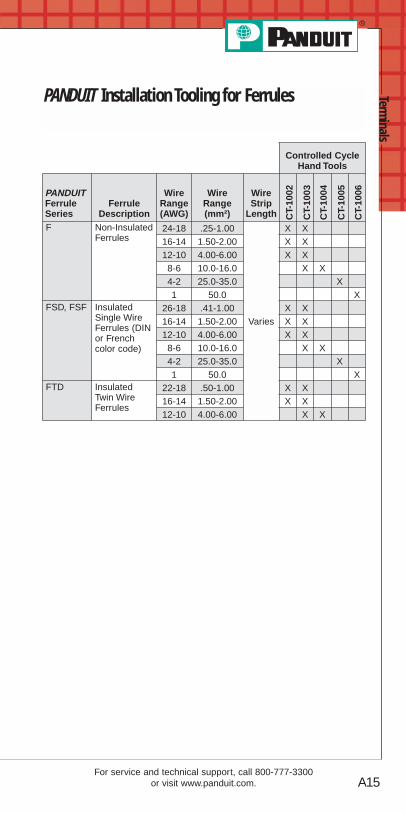
Controlled CycleHand Tools
PANDUITFerruleSeries
FerruleDescription
WireRange(AWG)
WireRange(mm²)
WireStrip
LengthF Non-Insulated
Ferrules24-18 .25-1.00
Varies
X X16-14 1.50-2.00 X X12-10 4.00-6.00 X X8-6 10.0-16.0 X X4-2 25.0-35.0 X1 50.0 X
FSD, FSF InsulatedSingle WireFerrules (DINor Frenchcolor code)
26-18 .41-1.00 X X16-14 1.50-2.00 X X12-10 4.00-6.00 X X8-6 10.0-16.0 X X4-2 25.0-35.0 X1 50.0 X
FTD InsulatedTwin WireFerrules
22-18 .50-1.00 X X16-14 1.50-2.00 X X12-10 4.00-6.00 X X
CT-
1002
CT-
1003
CT-
1004
CT-
1005
CT-
1006
PANDUIT Installation Tooling for Ferrules

Term
inal
s
A16
Prime items appear in BOLD.
Order number of pieces required, in multiples of Standard Package Quantity.
Hand Operated Plier Type Tools• Installer controlled crimp
• General purpose
• Plier type crimp for #22 thru #10 insulatedand non-insulated terminal products
CT-260
CT-200 CT-160 CT-100
Termination Tooling
Part Number Part Description
Std.Pkg.Qty.
CT-260 Crimps insulated and non-insulated terminals.Forged steel tool. Cuts wire.
1
CT-200 Crimps most PANDUIT #18 – #10 AWGnon-insulated terminals, disconnects and splices.Forged steel tool. Cuts wire.
1
CT-160 Crimps most PANDUIT #26 – #10 AWG insulatedand non-insulated terminals, disconnects andsplices. Cuts three U.S. and three Metricscrew sizes. Cuts and strips wire. Has insulationclosure pocket.
1
CT-100 Crimps most PANDUIT #26 – #10 AWG insulatedand non-insulated terminals, disconnects andsplices. Cuts #4, #6, #8 and #10 screw sizes. Cutsand strips wire. Excellent all-around applicationtool of heat treated finished steel with comfortablecushioned plastic grip handles.
1

Terminals
A17
Prime items appear in BOLD.
For service and technical support, call 800-777-3300or visit www.panduit.com.
CONTOUR CRIMP™ Controlled Cycle Tools• Specifically designed for the installation of
PAN-TERM ® terminals, disconnects and splices
• Controlled cycle mechanism assures highquality, consistent terminations
• Ergonomic tool design assures operatorcomfort, safety, and performance
• Polypropylene handles provide chemicalresistance and a cushioned, non-slip grip
• Multi-position locator facilitates a high qualityrepeatable crimp
CT-1525
CT-1550
CT-1551
CT-1570
CT- 1700
CT-1701
CT-1014
CT-1015
PartNumber Part Description
Std.Pkg.Qty.
CT-1525 Crimps PANDUIT #26 – #22 AWG insulatedterminals and splices, #22 – #10 AWG fullyinsulated disconnects and insulated parallel splices.Crimps PANDUIT #22 – #14 AWG barrelinsulated disconnects.
1
CT-1550 Crimps most PAN-TERM ® #22 – #10 AWG nylon andvinyl insulated terminals, splices and disconnects.The CT-1550 has the red/blue pocket closest to thepivot which provides a reduced crimp effort for thosewho make red/blue terminations.
1
CT-1551 Crimps most PAN-TERM ® #22 – #10 AWG nylon andvinyl insulated terminals, splices and disconnects.The CT-1551 has the yellow pocket closest to thepivot which provides a reduced crimp effort for thosewho make yellow terminations.
1
CT-1570 Crimps most PAN-TERM ® #22 – #10 AWG and.5 – 6.0mm non-insulated terminals and disconnects.Crimps PANDUIT #22 – #10 AWG and .5 – 6.0mmnon-insulated splices, and #10 AWG compression lugs.
1
CT-1700 Crimps PANDUIT #8 – #2 AWG non-insulated tubularterminals (S series), #8 – #1 AWG copper lugs andsplices, #6 – #4 AWG aluminum lugs and splices andCTAPF copper taps for #14 – #3 AWG. Includes fiveposition, color coded rotating die.
1
CT-1701 Crimps PANDUIT #10 – #2 AWG non-insulated largegauge ring terminal (P series). Crimps #8 – #1 AWGcopper lugs and splices, and #6 – #4 AWG aluminumlugs and splices, and #14 – #3 AWG CTAPF coppertaps. Includes 5 position rotating die.
1
CT-1014 Crimps PANDUIT #22 – #14 AWG loose pieceDISCO-LOK ™ disconnects.
1
CT-1015 Crimps PANDUIT #22 – #14 AWG loose pieceSUPRA-GRIP™ disconnects.
1

Term
inal
s
A18
Prime items appear in BOLD.
Order number of pieces required, in multiples of Standard Package Quantity.
Controlled Cycle Crimping Tools
Ferrule End Sleeve Crimping Tools
• Speciality crimping tools for fully insulated right angle disconnects and heat shrink insulated terminals,disconnects, and splices.
PartNumber Part Description
Std.Pkg.Qty.
CT-300-1 Crimps PANDUIT #22 – #14 AWG fully insulatedright angle disconnects. (DNFR-FIB series).
1
PartNumber Part Description
Std.Pkg.Qty.
CT-1002 Crimps PANDUIT #26 – #10 AWG single vinylinsulated ferrules (DIN). #26 – #10 AWG singlewire insulated ferrules (French).#22 – #12 AWG vinyl insulated dual-wire ferrules(DIN). #24 – #10 AWG non-insulated ferrules.
1
CT-1003 Crimps PANDUIT #22 – #8 AWG single wireinsulated ferrules (DIN). #22 – #8 AWG single wirevinyl insulated ferrules (French). #22 – #10 AWGvinyl insulated dual-wire (DIN) ferrules. #22 – #10AWG non-insulated ferrules.
1
CT-1004 Crimps PANDUIT #8 – #6 AWG single wire vinylinsulated ferrule (DIN). #8 – #6 AWG single wirevinyl insulated ferrules (French).#10 AWG vinyl insulated dual-wire (DIN) ferrule.#8 – #6 AWG non-insulated ferrules.
1
CT-1005 Crimps PANDUIT #4 – #2 AWG single wire vinylinsulated ferrule (DIN). #4 – #2 AWG single wirevinyl insulated ferrules (French).#4 – #2 AWG non-insulated ferrules.
1
CT-1006 Crimps PANDUIT #1 AWG single wire vinylinsulated ferrule (DIN) and (French). #1 AWGnon-insulated ferrules.
1
• Specifically designed for the installation ofPAN-TERM ® ferrules
• Controlled cycle mechanism assures highquality, consistent terminations
• Ergonomic tool design assures operatorcomfort, safety and performance
• Multi-position locator facilitates a highquality repeatable crimp
CT-1002
CT-1003
CT-1004 CT-1005 CT-1006
Terminals
A19
Prime items appear in BOLD.
For service and technical support, call 800-777-3300or visit www.panduit.com.
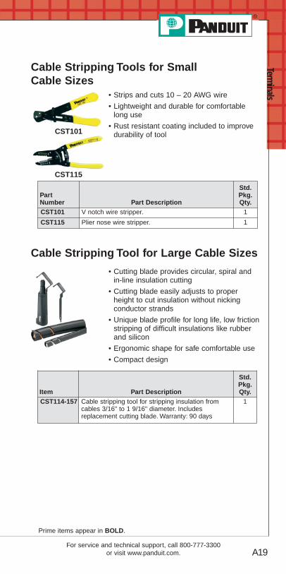
Cable Stripping Tools for SmallCable Sizes
• Strips and cuts 10 – 20 AWG wire
• Lightweight and durable for comfortablelong use
• Rust resistant coating included to improvedurability of tool
Cable Stripping Tool for Large Cable Sizes
• Cutting blade provides circular, spiral andin-line insulation cutting
• Cutting blade easily adjusts to properheight to cut insulation without nickingconductor strands
• Unique blade profile for long life, low frictionstripping of difficult insulations like rubberand silicon
• Ergonomic shape for safe comfortable use
• Compact design
CST101
CST115
PartNumber Part Description
Std.Pkg.Qty.
CST101 V notch wire stripper. 1
CST115 Plier nose wire stripper. 1
Item Part Description
Std.Pkg.Qty.
CST114-157 Cable stripping tool for stripping insulation fromcables 3/16" to 1 9/16" diameter. Includesreplacement cutting blade. Warranty: 90 days
1

Term
inal
s
A20
Features and Benefits – PAN-TERM® Terminals
Non-Insulated TerminalsType P
Maximum recommended operating temperature 150°C (302°F)
Extended barrel lengthassures a good qualitycrimp and makes crimping easier
Productmarkings provide easy identification ofwire size
Brazed seam assures crimp reliability
Internally beveledbarrel for quick easywire insertion
Internal barrel serrationsassure good wirecontact and maximumtensile strength
UL and CSA rated up to 2000V per UL486A.Nickel plated terminals rated up to 343°C (650°F)maximum operating temperature.
All PANDUIT Terminals feature high quality materials made withelectrolytic copper for high conductivity and are tin plated forcorrosion resistance.
Nylon Insulated Terminals With Insulation Grip Sleeve
Type PN or PNF
UL and CSA rated up to 600V per UL486.Flammability – UL94V-2/HB.Proprietary blend of UL94V-2 and UL94HBflammability rated materials.
Internal barrelserrations assuregood wire contactand maximumtensile strength
Maximum insulation temperature 105°C (221°F)
Color codedinsulation identifieswire range
Funnel entry forfaster insertion andlower installed cost
Insulation grip sleeveprovides a superiorinsulation crimp for highvibration and high strainrelief applications

Terminals
A21For service and technical support, call 800-777-3300
or visit www.panduit.com.
Features and Benefits – PAN-TERM® Terminals(continued)
Vinyl Insulated Terminals With Insulation Support
Type PV
Funnel entry for fasterinsertion and lowerinstalled cost
Brazed seam assurescrimp reliability
Internal barrelserrations assuregood wire contactand maximumtensile strength
Insulation crimpprovides insulationsupport to protectelectrical crimp
Color coded insulationidentifies wire range
Maximum insulationtemperature 105°C (221°F)
UL and CSA rated up to 600V per UL486.Flammability – UL94V-0.
Non-Insulated Seamless Tubular TerminalsType S
UL and CSA rated up to 2000V per UL486A.
Internally beveledbarrel for quickeasy wire insertion
Maximum recommendedoperating temperature150°C (302°F)
Double thickness provides a strongring tongue
Product markingsprovide easyidentification ofwire sizes
Inspection hole allowsvisual inspection forproper wire insertion
Seamless tubularbarrel providesconsistent, highperformance,quality crimps
Term
inal
s
A22
Prime items appear in BOLD.
Order number of pieces required, in multiples of Standard Package Quantity.
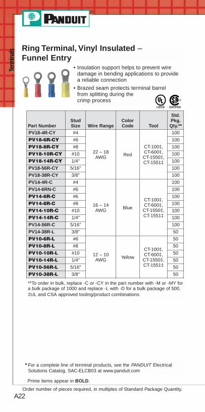
Ring Terminal, Vinyl Insulated –Funnel Entry
• Insulation support helps to prevent wiredamage in bending applications to providea reliable connection
• Brazed seam protects terminal barrelfrom splitting during thecrimp process
**To order in bulk, replace -C or -CY in the part number with -M or -MY fora bulk package of 1000 and replace -L with -D for a bulk package of 500.‡UL and CSA approved tooling/product combinations.
◆ For a complete line of terminal products, see the PANDUIT ElectricalSolutions Catalog, SAC-ELCB03 at www.panduit.com
Part NumberStudSize Wire Range
ColorCode Tool
Std.Pkg.Qty.**
PV18-4R-CY #4
22 – 18AWG Red
CT-100‡,CT-600‡,CT-1550‡,CT-1551‡
100
PV18-6R-CY #6 100
PV18-8R-CY #8 100
PV18-10R-CY #10 100
PV18-14R-CY 1/4" 100
PV18-56R-CY 5/16" 100
PV18-38R-CY 3/8" 100
PV14-4R-C #4
16 – 14AWG Blue
CT-100‡,CT-600‡,CT-1550‡,CT-1551‡
100
PV14-6RN-C #6 100
PV14-6R-C #6 100
PV14-8R-C #8 100
PV14-10R-C #10 100
PV14-14R-C 1/4" 100
PV14-56R-C 5/16" 100
PV14-38R-L 3/8" 50
PV10-6R-L #6
12 – 10AWG Yellow
CT-100‡,CT-600‡,CT-1550‡,CT-1551‡
50
PV10-8R-L #8 50
PV10-10R-L #10 50
PV10-14R-L 1/4" 50
PV10-56R-L 5/16" 50
PV10-38R-L 3/8" 50

A23
Prime items appear in BOLD.
For service and technical support, call 800-777-3300or visit www.panduit.com.
Terminals
Multiple Stud Terminal, Vinyl Insulated –Funnel Entry
• Insulation support helps to prevent wiredamage in bending applications for areliable connection
• Brazed seam protects terminal barrelfrom splitting during thecrimp process
**To order in bulk, replace -C or -CY in the part number with -M or -MY fora bulk package of 1000 and replace -L with -D for a bulk package of 500.
‡UL and CSA approved tooling/product combinations.
Ring Terminal, Vinyl Expanded Insulation
• Insulation support helps to prevent wiredamage in bending applications
• Brazed seam protects terminal barrel fromsplitting during the crimp process
• Expanded funnel entry designed toaccommodate wire with a larger thanstandard outside diameter insulation
Part NumberStudSize
WireRange
ColorCode Tool
Std.Pkg.Qty.**
PV14-10RX-C #10 16 – 14AWG Blue CT-100‡,
CT-600‡,CT-1550‡,CT-1551‡
100
PV10-10RX-L #10 12 – 10AWG Yellow
50
PV10-14RX-L 1/4" 50
**To order in bulk, replace -C in the part number with -M for a bulkpackage of 1000 and replace -L with -D for a bulk package of 500.
‡UL and CSA approved tooling/product combinations.
Part NumberStudSize Wire Range
ColorCode Tool
Std.Pkg.Qty.**
PV18-610R-CY
#6, #8,#10
22 – 18AWG
Red
CT-100,CT-600‡,CT-1550‡,CT-1551‡
100
PV14-610R-C 16 – 14AWG
Blue 100
PV10-610R-L 12 – 10AWG
Yellow 50

A24
Prime items appear in BOLD.
Order number of pieces required, in multiples of Standard Package Quantity.
Term
inal
s Ring Terminal, Non-Insulated
• Brazed seam protects terminal barrel fromsplitting during the crimp process
• Barrel of terminal internally beveled toprovide quick and easywire insertion
**To order in bulk, replace -C in the part number with -M for a bulkpackage of 1000 and replace -L with -D for a bulk package of 500.
‡UL and CSA approved tooling/product combinations.
Part NumberStudSize
WireRange Tool
Std.Pkg.Qty.**
P18-6R-C #6
22 – 18 AWG
CT-100‡, CT-200‡, CT-600‡, CT-1570‡
100
P18-8R-C #8 100
P18-10R-C #10 100
P18-14R-C 1/4" 100
P14-6R-C #6
16 – 14 AWG
100
P14-8R-C #8 100
P14-10R-C #10 100
P14-14R-C 1/4" 100
P14-56R-C 5/16" 100
P14-38R-C 3/8" 100
P10-6R-L #6
12 – 10 AWG
50
P10-8R-L #8 50
P10-10R-L #10 50
P10-14R-L 1/4" 50
P10-56R-L 5/16" 50
P10-38R-L 3/8" 50
◆For a complete line of terminal products, see the PANDUIT ElectricalSolutions Catalog, SA-ELCB03 at www.panduit.com

A25
Prime items appear in BOLD.
For service and technical support, call 800-777-3300or visit www.panduit.com.
Terminals
Fork Terminal, Vinyl Insulated –Funnel Entry
• Insulation support helps to prevent wiredamage in bending applications
• Brazed seam protects terminalbarrel from splitting during thecrimp process
*Not UL Listed or CSA Certified.**To order in bulk, replace -C or -CY in the part number with -M or -MY
for a bulk package of 1000 and replace -L with -D for a bulk packageof 500.
‡UL and CSA approved tooling/product combinations.
Part NumberStudSize Wire Range
ColorCode Tool
Std.Pkg.Qty.**
PV22-6F-C* #6 26 – 22AWG
Yellow CT-100,CT-600,CT-1525
100
PV18-6FN-CY #6
22 – 18AWG Red
CT-100‡,CT-600‡,CT-1550‡,CT-1551‡
100
PV18-6F-CY #6 100
PV18-8F-CY #8 100
PV18-10F-CY #10 100
PV14-6FN-C #6
16 – 14AWG Blue
CT-100‡,CT-600‡,CT-1550‡,CT-1551‡
100
PV14-6F-C #6 100
PV14-8F-C #8 100
PV14-10FN-C #10 100
PV14-10F-C #10 100
PV14-14F-C 1/4" 100
PV10-6F-L #6
12 – 10AWG Yellow
CT-100‡,CT-600‡,CT-1550‡,CT-1551‡
50
PV10-8F-L #8 50
PV10-10F-L #10 50
PV10-14F-L 1/4" 50
A26
Prime items appear in BOLD.
Order number of pieces required, in multiples of Standard Package Quantity.
Term
inal
s
*Not UL Listed or CSA Certified.**To order in bulk, replace -C in the part number with -M for a bulk
package of 1000 and replace -L with -D for a bulk package of 500.‡UL and CSA approved tooling/product combinations.
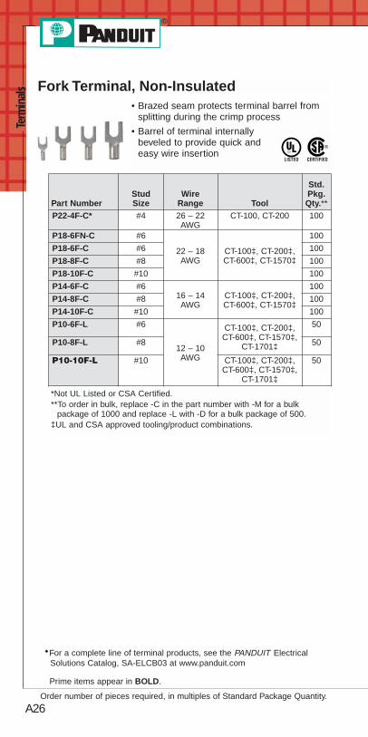
Fork Terminal, Non-Insulated• Brazed seam protects terminal barrel from
splitting during the crimp process
• Barrel of terminal internallybeveled to provide quick andeasy wire insertion
Part NumberStudSize
WireRange Tool
Std.Pkg.Qty.**
P22-4F-C* #4 26 – 22AWG
CT-100, CT-200 100
P18-6FN-C #6
22 – 18AWG
CT-100‡, CT-200‡,CT-600‡, CT-1570‡
100
P18-6F-C #6 100
P18-8F-C #8 100
P18-10F-C #10 100
P14-6F-C #616 – 14AWG
CT-100‡, CT-200‡,CT-600‡, CT-1570‡
100
P14-8F-C #8 100
P14-10F-C #10 100
P10-6F-L #6
12 – 10AWG
CT-100‡, CT-200‡,CT-600‡, CT-1570‡,
CT-1701‡
50
P10-8F-L #8 50
P10-10F-L #10 CT-100‡, CT-200‡,CT-600‡, CT-1570‡,
CT-1701‡
50
◆For a complete line of terminal products, see the PANDUIT ElectricalSolutions Catalog, SA-ELCB03 at www.panduit.com

A27
Prime items appear in BOLD.
For service and technical support, call 800-777-3300or visit www.panduit.com.
Terminals
Locking Fork Terminal, Vinyl Insulated –Funnel Entry
• Insulation support helps to prevent wiredamage in bending applications
• Brazed seam protects terminalbarrel from splitting during thecrimp process
**To order in bulk, replace -C or -CY in the part number with -M or -MYfor a bulk package of 1000 and replace -L with -D for a bulk packageof 500.
‡UL and CSA approved tooling/product combinations.
Locking Fork Terminal, Non-Insulated• Brazed seam protects terminal barrel from
splitting during the crimp process
• Barrel of terminal internallybeveled to provide quick andeasy wire insertion
Part NumberStudSize
WireRange Tool
Std.Pkg.Qty.**
P18-6LF-C #6 22 – 18AWG
CT-100‡, CT-200‡,CT-600‡, CT-1570‡
100
P14-6LF-C #6 16 – 14AWG
CT-100‡, CT-200‡,CT-600‡, CT-1570‡
100
P10-10LF-L #10 12 – 10AWG
CT-100‡, CT-200‡,CT-600‡, CT-1570‡,
CT-1701‡
50
**To order in bulk, replace -C in the part number with -M for a bulkpackage of 1000 and replace -L with -D for a bulk package of 500.
‡UL and CSA approved tooling/product combinations.
Part NumberStudSize
WireRange
ColorCode Tool
Std.Pkg.Qty.
PV18-6LF-CY #622 – 18AWG Red
CT-100‡,CT-600‡,CT-1550‡,CT-1551‡
100
PV18-8LF-CY #8 100
PV18-10LF-CY #10 100
PV14-6LF-C #616 – 14AWG Blue
CT-100‡,CT-600‡,CT-1550‡,CT-1551‡
100
PV14-8LF-C #8 100
PV14-10LF-C #10 100
PV10-6LF-L #6
12 – 10AWG Yellow
CT-100‡,CT-600‡,CT-1550‡,CT-1551‡
50
PV10-8LF-L #8 50
PV10-10LF-L #10 50
PV10-14LF-L 1/4" 50

A28
Prime items appear in BOLD.
Order number of pieces required, in multiples of Standard Package Quantity.
Term
inal
s Pin Terminal, Vinyl Insulated –Funnel Entry
• Insulation support helps to prevent wiredamage in bending applications for areliable connection
• Brazed seam protects terminal barrel fromsplitting during the crimp process
• Solid pin designed to prevent damage tothe wire from over tightening, resulting in areliable electrical connection
**To order in bulk, replace -C or -CY in the part number with -M or -MYfor a bulk package of 1000 and replace -L with -D for a bulk packageof 500.
Pin Terminal, Non-Insulated• Brazed seam protects terminal barrel from
splitting during the crimp process
• Barrel of terminal internally beveled toprovide quick and easy wire insertion
• Solid pin designed to prevent damage tothe wire from over tightening, resulting in areliable electrical connection
Part NumberStudSize
WireRange Tool
Std.Pkg.Qty.**
P18-P47-C — 22 – 18AWG
CT-100, CT-200,CT-260, CT-1570
100
P14-P47-C — 16 – 14AWG
CT-100, CT-200,CT-260, CT-1570
100
P10-P55-L — 12 – 10AWG
CT-100, CT-200,CT-260, CT-1570
50
**To order in bulk, replace -C in the part number with -M for a bulkpackage of 1000 and replace -L with -D for a bulk package of 500.
◆For a complete line of terminal products, see the PANDUIT ElectricalSolutions Catalog, SA-ELCB03 at www.panduit.com
Part Number Stud Size Wire Range Tool
Std.Pkg.Qty.
PV18-P47-CY — 22 – 18AWG
CT-100, CT-260,CT-1550, CT-1551
100
PV14-P47-C — 16 – 14AWG
CT-100, CT-260,CT-1550, CT-1551
100
PV10-P55-L — 12 – 10AWG
CT-100, CT-260,CT-1550, CT-1551
50
A29For service and technical support, call 800-777-3300
or visit www.panduit.com.
Terminals
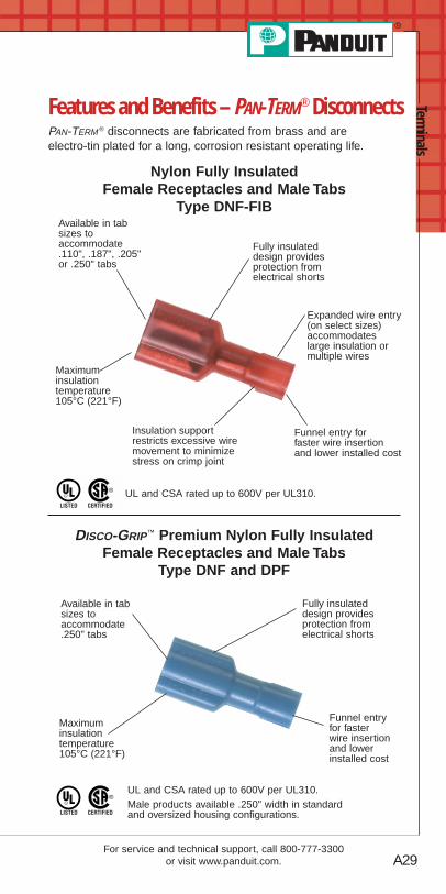
Features and Benefits – PAN-TERM® DisconnectsPAN-TERM ® disconnects are fabricated from brass and areelectro-tin plated for a long, corrosion resistant operating life.
Nylon Fully Insulated Female Receptacles and Male Tabs
Type DNF-FIB
Maximuminsulationtemperature105°C (221°F)
Insulation supportrestricts excessive wiremovement to minimizestress on crimp joint
UL and CSA rated up to 600V per UL310.
Funnel entry for faster wire insertionand lower installed cost
Expanded wire entry(on select sizes)accommodateslarge insulation ormultiple wires
Available in tabsizes toaccommodate .110", .187", .205"or .250" tabs
Fully insulateddesign providesprotection fromelectrical shorts
DISCO-GRIP™ Premium Nylon Fully InsulatedFemale Receptacles and Male Tabs
Type DNF and DPF
Maximuminsulationtemperature105°C (221°F)
UL and CSA rated up to 600V per UL310.Male products available .250" width in standardand oversized housing configurations.
Funnel entry for faster wire insertionand lowerinstalled cost
Available in tabsizes toaccommodate.250" tabs
Fully insulateddesign providesprotection fromelectrical shorts
A30
Term
inal
s
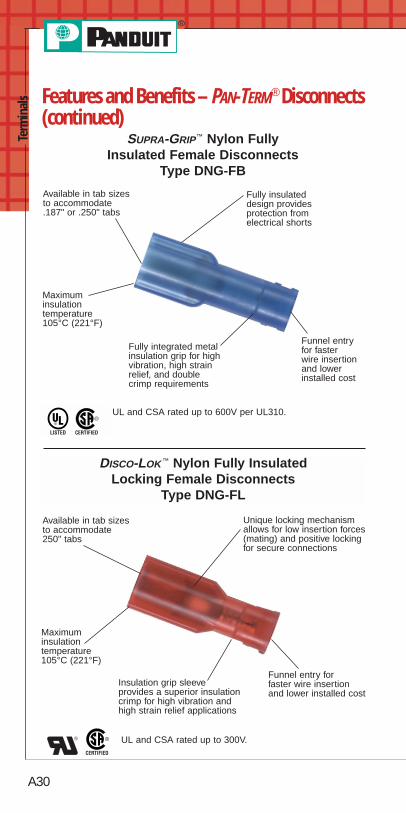
SUPRA-GRIP™ Nylon Fully Insulated Female Disconnects
Type DNG-FB
Maximuminsulationtemperature105°C (221°F)
Fully integrated metalinsulation grip for highvibration, high strainrelief, and double crimp requirements
Funnel entry for faster wire insertionand lowerinstalled cost
Available in tab sizesto accommodate .187" or .250" tabs
Fully insulateddesign providesprotection fromelectrical shorts
UL and CSA rated up to 600V per UL310.
DISCO-LOK ™ Nylon Fully Insulated Locking Female Disconnects
Type DNG-FL
Maximuminsulationtemperature105°C (221°F)
Insulation grip sleeve provides a superior insulationcrimp for high vibration andhigh strain relief applications
UL and CSA rated up to 300V.
Funnel entry for faster wire insertion and lower installed cost
Available in tab sizesto accommodate 250" tabs
Unique locking mechanismallows for low insertion forces(mating) and positive lockingfor secure connections
Features and Benefits – PAN-TERM® Disconnects(continued)

A31For service and technical support, call 800-777-3300
or visit www.panduit.com.
TerminalsNylon Barrel Insulated
Female Receptacles and Male TabsType DNF
Insulation grip sleeve providesa superior insulation crimp forhigh vibration and high strainrelief applications
Funnel entryfor faster wire insertionand lowerinstalled cost
Available in tabsizes toaccommodate .110", .187", .205" or.250" tabs
UL and CSA rated up to 300V.Male products available .250" width.
Maximum insulationtemperature 105°C (221°F)
Vinyl Barrel Insulated Female Receptacles and Male Tabs
Type DV and DVF
Insulation support toprotect electrical crimp
Available intab sizes toaccommodate .187", .205" or .250" tabs
UL and CSA rated up to 600V.Male products available .250" width.Flammability – UL94V-0.
Maximum insulationtemperature 105°C (221°F)
Non-Insulated Female Receptacles and Male TabsType D
Male products available .250" width.
Available in tab sizesto accommodate .187" or .250" tabs
Sleeved barrel assurescrimp reliability
Maximum recommendedoperating temperature150°C (302°F)
Features and Benefits – PAN-TERM® Disconnects(continued)

A32
Prime items appear in BOLD.
Order number of pieces required, in multiples of Standard Package Quantity.
Term
inal
s
Female Disconnect Nylon FullyPre-Insulated – Funnel Entry
• Insulation support helps to prevent wiredamage in bending applications
• Internal wire stop assures proper length ofinsertion into terminal barrel
**To order in bulk, replace -C in the part number with -M for a bulkpackage of 1000 and replace -L with -D for a bulk package of 500.
‡UL and CSA approved tooling/product combinations.
Part Number
TabSize(In.)
WireRange
ColorCode Tool
Std.Pkg.Qty.**
DNF18-110FIB-C .110 x .032
22 – 18AWG Red
CT-100,CT-600,
CT-1525‡
100
DNF18-111FIB-C .110 x .020 100
DNF18-187FIB-C .187 x .032 100
DNF18-188FIB-C .187 x .020 100
DNF18-205FIB-C .205 x .032 100
DNF18-206FIB-C .205 x .020 100
DNF18-250FIB-C .250 x .032 100
DNF14-187FIB-C .187 x .032
16 – 14AWG Blue
CT-100,CT-600,
CT-1525‡
100
DNF14-188FIB-C .187 x .020 100
DNF14-205FIB-C .205 x .032 100
DNF14-206FIB-C .205 x .020 100
DNF14-250FIB-C .250 x .032 100
DNF10-250FIB-L .250 x .032 12 – 10AWG
Yellow CT-1525‡ 50
PAN-TERM® Disconnects
◆For a complete line of terminal products, see the PANDUIT ElectricalSolutions Catalog, SA-ELCB03 at www.panduit.com

A33
Prime items appear in BOLD.
For service and technical support, call 800-777-3300or visit www.panduit.com.
Terminals
Male/Female Coupler, Nylon FullyPre-Insulated – Funnel Entry
• Insulation support helps to prevent wiredamage in bending applications
• Internal wire stop assures properlength of insertion intoterminal barrel
*UL Listed only.**To order in bulk, replace -C in the part number with -M for a bulk
package of 1000 and replace -L with -D for a bulk package of 500.‡UL and CSA approved tooling/product combinations.
Female Disconnect, Vinyl BarrelInsulated – Butted Seam
• Insulation support helps to prevent wiredamage in bending applications
*UL Recognized and CSA approved.**To order in bulk, replace -C or -CY in the part number with -M or -MY for
a bulk package of 1000.^CSA approved tooling/product combinations.‡UL and CSA approved tooling/product combinations.
Part Number
TabSize(In.)
WireRange
ColorCode Tool
Std.Pkg.Qty.**
DNF18-250FIM-C.250 x.032
22 – 18AWG Red
CT-100‡, CT-600,CT-1525‡
100
DNF18-250FIB-C CT-100, CT-600,CT-1525‡
100
DNF14-250FIM-C .250 x.032
16 – 14AWG Blue CT-600,
CT-1525‡100
DNF14-250FIMB-L 50DNF10-250FIMB-L*
.250 x.032
12 – 10AWG Yellow
CT-600‡,CT-1550‡,CT-1551‡
50
DNF10-250FI-L CT-100‡, CT-460‡,CT-550‡, CT-600‡,
CT-1550‡,CT-1551‡
50
*Recognized
Part Number
TabSize(In.)
WireRange
ColorCode Tool
Std.Pkg.Qty.**
DV18-187B-CY .187 x .03222 – 18AWG Red CT-1525‡
100
DV18-188B-CY .187 x .020 100
DV18-250B-CY .250 x .032 100
DV14-187B-C* .187 x .032
16 – 14AWG Blue CT-1525^
100
DV14-188B-C* .187 x .020 100
DV14-205B-C* .205 x .032 100
DV14-250B-C* .250 x .032 100

A34
Prime items appear in BOLD.
Order number of pieces required, in multiples of Standard Package Quantity.
Term
inal
s Female Disconnect, Non-Insulated –Butted Seam
**To order in bulk, replace -C in the part number with -M for a bulkpackage of 1000.
Piggyback Disconnect, Vinyl Insulated• Metal insulation grip sleeve crimps to wire
insulation providing protection to the crimpjoint during high vibration applications
• Combination of female disconnect and maletab allows versatility in points of connection
• Multiple connection points allow additionalcircuits to be added to existingequipment withoutexpensive rework
**To order in bulk, replace -C or -CY in the part number with -M or -MY for a bulk package of 1000.
Disconnect Adapter, Non-Insulated• Converts one male tab to two male tabs,
allowing two female disconnects to beconnected to the same circuit
**To order in bulk, replace -C in the part number with -M for a bulk package of 1000.
Part Number
TabSize(In.)
WireRange Tool
StdPkg.Qty.**
D14-250B-C .250 x .032 16 – 14 AWG CT-100 100
Part Number
TabSize(In.)
WireRange
Std.Pkg.Qty.**
D-250A-C .250 x .032 — 100
◆For a complete line of terminal products, see the PANDUIT ElectricalSolutions Catalog, SA-ELCB03 at www.panduit.com
• Non-insulated barrel can be used toprovide an economical termination wheninsulation is not required
Part Number
TabSize(In.) Wire Range
ColorCode Tool
Std.Pkg.Qty.**
DV18-250P-CY.250 x.032
22 – 18AWG
Red CT-100,CT-260,CT-1550,CT-1551
100
DV14-250P-C 16 – 14AWG
Blue 100

A35
Prime items appear in BOLD.
For service and technical support, call 800-777-3300or visit www.panduit.com.
Terminals
Right Angle Female Disconnect, NylonFully Insulated – Funnel Entry
• Insulation support helps to prevent wiredamage in bending applications
• Right angle design allows lowprofile routing of wire in limitedapplication space
**To order in bulk, replace -C in the part number with -M for a bulkpackage of 1000.
Part Number
TabSize (In.)
WireRange
ColorCode Tool
Std.Pkg.Qty.**
DNFR18-250FIB-C .250 x .032 22 – 18AWG
Red CT-300-1 100
DNFR14-250FIB-C .250 x .032 16 – 14AWG
Blue CT-300-1 100
Right Angle Female Disconnect, NylonInsulated – Funnel Entry
• Insulation support helps to prevent wiredamage in bending applications
• Right angle design allows low profilerouting of wire in limitedapplication space
**To order in bulk, replace -C in the part number with -M for a bulkpackage of 1000.
‡UL and CSA approved tooling/product combinations.
Part Number
TabSize(In.)
WireRange
ColorCode Tool
Std.Pkg.Qty.**
DNFR18-250B-C .250 x .032 22 – 18AWG
Red CT-1525‡ 100
DNFR14-250B-C .250 x .032 16 – 14AWG
Blue CT-1525‡ 100
A36
Prime items appear in BOLD.
Order number of pieces required, in multiples of Standard Package Quantity.
Term
inal
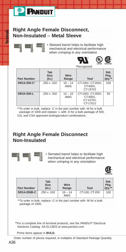
s Right Angle Female Disconnect,Non-Insulated – Metal Sleeve
• Sleeved barrel helps to facilitate highmechanical and electrical performancewhen crimping in any orientation
**To order in bulk, replace -C in the part number with -M for a bulkpackage of 1000 and replace -L with -D for a bulk package of 500.
‡UL and CSA approved tooling/product combinations.
Right Angle Female DisconnectNon-Insulated
• Serrated barrel helps to facilitate highmechanical and electrical performancewhen crimping in any orientation
**To order in bulk, replace -C in the part number with -M for a bulkpackage of 1000.
*Recognized
Part Number
TabSize(In.)
WireRange Tool
Std.Pkg.Qty.**
DR14-250-C* .250 x .032 16 – 14AWG
CT-100‡, CT-200‡,CT-600‡,CT-1570‡
100
DR10-250-L .250 x .032 12 – 10AWG
CT-100‡, CT-200‡,CT-600‡,CT-1570‡,CT-1701‡
50
Part Number
TabSize(In.)
WireRange Tool
Std.Pkg.Qty.**
DR14-250B-C .250 x .032 16 – 14AWG
CT-100, CT-200 100
◆For a complete line of terminal products, see the PANDUIT ElectricalSolutions Catalog, SA-ELCB03 at www.panduit.com

A37
Prime items appear in BOLD.
For service and technical support, call 800-777-3300or visit www.panduit.com.
Terminals
Male Disconnect, Nylon BarrelInsulated – Funnel Entry
• Metal insulation grip sleeve crimps to wireinsulation providing protection to the crimpjoint during high vibration applications
*Not CSA Certified.**To order in bulk, replace -C in the part number with -M for a bulk
package of 1000 and replace -L with -D for a bulk package of 500.
Part Number
TabSize(In.)
WireRange
ColorCode Tool
Std.Pkg.Qty.**
DNF18-250M-C .250 x .032 22 – 18AWG
Red
CT-1550,CT-1551
100
DNF14-250M-C .250 x .032 16 – 14AWG
Blue 100
DNF10-250M-L* .250 x .032 12 – 10AWG
Yellow 50
Male Disconnect, Vinyl BarrelInsulated – Funnel Entry
**To order in bulk, replace -C or -CY in the part number with -M or -MY fora bulk package of 1000.
• Butted seam offers an economical solutionfor less demanding applications
Part NumberTab Size
(In.)Wire
RangeColorCode Tool
StdPkg.Qty.**
DV18-250MB-CY .250 x.032
22 – 18AWG
RedCT-1550,CT-1551
100
DV14-250MB-C .250 x.032
16 – 14AWG
Blue 100

A38
Prime items appear in BOLD.
Order number of pieces required, in multiples of Standard Package Quantity.
Term
inal
s Male Disconnect, Non-Insulated –Butted Seam
Part Number
TabSize(In.)
WireRange Tool
Std.Pkg.Qty.**
D14-250MB-C .250 x .032 16 – 14AWG
CT-100 100
**To order in bulk, replace -C in the part number with -M for a bulkpackage of 1000.
Male Blade Adapter, Vinyl Insulated –Funnel Entry
• Brazed seam protects terminal barrel fromsplitting during the crimp process
• Flat blade design to prevent damage tothe wire from over tightening, resulting in areliable electrical connection
• Designed specifically for blade-typeterminal blocks
• Insulation support helps to preventwire damage inbending applications
**To order in bulk, replace -C or -CY in the part number with -M or -MY fora bulk package of 1000.
‡UL and CSA approved tooling/product combinations.
*Recognized
◆For a complete line of terminal products, see the PANDUIT ElectricalSolutions Catalog, SA-ELCB03 at www.panduit.com
• Butted seam offers an economicalsolution for less demanding applications
Part NumberTab Size
(In.)Wire
RangeColorCode Tool
Std.Pkg.Qty.
DV18-145M-CY .145 x .032 22 – 18AWG
RedCT-600,
CT-1550‡,CT-1551‡
100
DV14-145M-C .145 x .032 16 – 14AWG
Blue 100

A39For service and technical support, call 800-777-3300
or visit www.panduit.com.
Terminals
Features and Benefits – PAN-TERM® Splices
Non-Insulated Parallel SplicesType PS
Nylon Parallel SplicesType PSN
Maximum recommended operatingtemperature150°C (302°F)
Seamlesstubular barrelprovidesconsistent highperformancequality crimps
UL and CSA rated up to 300V.
Only one crimpneeded tocomplete splice
Only onecrimp neededto completesplice
Maximum insulationtemperature 105°C(221°F)

A40
Term
inal
s Features and Benefits – PAN-TERM® Splices(continued)
Internal wirestops assureproper insertionlength
Maximum insulationtemperature 105°C(221°F)
Brazed seamassures crimpreliability
UL and CSA rated up to 600V.
Maximum insulationtemperature 105°C(221°F)
Internal wirestops assureproperinsertionlength
Expanded wire entryaccommodateslarger insulation
UL and CSA rated up to 600V.Flammability – UL94V-0.Metric versions available.
Brazed seamassures crimpreliability
Nylon Butt SplicesType BSN
Vinyl Butt SplicesType BSV
Non-Insulated Butt SplicesType BS
Internally beveledbarrel for quick easywire insertion
Internal wire stopsassure properinsertion length
UL and CSA rated up to 600V.Metric versions available.
Brazed seamassures crimpreliability
Maximum recommendedoperating temperature150°C (302°F)

A41
Prime items appear in BOLD.
For service and technical support, call 800-777-3300or visit www.panduit.com.
TerminalsButt Splice, Nylon Insulated
• Brazed seam protects terminal barrel fromsplitting during the crimp process
• Internal wire stop assures proper length ofinsertion into terminal barrel
*Not UL Listed.**To order in bulk, replace -C in the part number with -M for a bulk
package of 1000 and replace -L with -D for a bulk package of 500.
Part NumberWire
RangeColorCode Tool
Std.Pkg.Qty.**
BSN22-C* 26 – 22 AWG Yellow CT-100, CT-1525 100
BSN18-C 22 – 18 AWG RedCT-100, CT-600,
CT-1550, CT-1551
100
BSN14-C 16 – 14 AWG Blue 100
BSN10-L 12 – 10 AWG Yellow 50
PAN-TERM® Splices
Butt Splice, Vinyl Insulated
• Expanded funnel entry designed toaccommodate wire with a larger thanstandard outside diameter insulation
• Insulation support helps to prevent wiredamage in bending applications
• Internal wire stop assures proper length ofinsertion into terminal barrel
**To order in bulk, replace -C or -CY in the part number with -M or -MYfor a bulk package of 1000 and replace -L with -D for a bulk packageof 500.
Part Number Wire Range Color Code Tool
Std.Pkg.Qty.
BSV18X-CY 22 – 18 AWG RedCT-100, CT-600,
CT-1550, CT-1551
100
BSV14X-C 16 – 14 AWG Blue 100
BSV10X-L 12 – 10 AWG Yellow 50

A42
Prime items appear in BOLD.
Order number of pieces required, in multiples of Standard Package Quantity.
Term
inal
s Butt Splice, Non-Insulated• Brazed seam protects terminal barrel from
splitting during the crimp process
• Internal wire stop assuresproper length of insertion intoterminal barrel
*Not UL Listed.**To order in bulk, replace -C in the part number with -M for a bulk
package of 1000 and replace -L with -D for a bulk package of 500.‡UL and CSA approved tooling/product combinations.
Part NumberWire
Range Tool
Std.Pkg.Qty.**
BS22-C* 26 – 22 AWG CT-100 100
BS18-C 22 – 18 AWG CT-100, CT-200,CT-600, CT-1570
100
BS14-C 16 – 14 AWG 100
BS10-L 12 – 10 AWG CT-100, CT-200,CT-600, CT-1570,
CT-1701‡
50
Parallel Splice, Nylon Insulated• Parallel design results in only one crimp
required to combine two wires
Parallel Splice, Non-Insulated• Parallel design results in only one crimp
required to combine two wires
• Non-insulated barrel can be used to providean economical terminationwhen insulation is not required
**To order in bulk, replace -C in the part number with -M for a bulkpackage of 1000.
**To order in bulk, replace -C in the part number with -M for a bulkpackage of 1000 and replace -L with -D for a bulk package of 500.
Part NumberWire
Range Tool
Std.Pkg.Qty.**
PS16-C 20 – 16 AWGCT-100, CT-200
100
PS12-L 14 – 12 AWG 50
◆For a complete line of terminal products, see the PANDUIT ElectricalSolutions Catalog, SA-ELCB03 at www.panduit.com
Part NumberWire
RangeColorCode Tool
Std.Pkg.Qty.**
PSN18-C 22 – 18 AWG Red CT-100,CT-1525
100
PSN16-C 20 – 16 AWG Blue 100

A43For service and technical support, call 800-777-3300
or visit www.panduit.com.
Terminals
Features and Benefits – PAN-TERM® Wire Joints
Non-Insulated Wire JointsType J
Nylon Wire JointsType JN
Internallybeveled barrelfor quick easywire insertion
UL and CSA rated up to 600V.
Maximum recommended operatingtemperature150°C (302°F)
Only one crimpneeded tocomplete splice
Maximum insulationtemperature 105°C(221°F)
Deep skirt toaccommodatemultiple variations ofwire combinations
Only onecrimp neededto completesplice
UL and CSA rated up to 600VMetric versions available
Fully insulatedhousing protectscrimp joint

A44
Prime items appear in BOLD.
Order number of pieces required, in multiples of Standard Package Quantity.
Term
inal
s
Wire Joint, Nylon Insulated• Large barrel designed to accommodate
multiple combinations of wires (up to sevenwires) with just one crimp
• Fully pre-insulated housing designed toprotect crimp joint and reducethe potential for shortingand shocks
**To order in bulk, replace -C in the part number with -M for a bulkpackage of 1000, with exception of JN418-212-C, replace -C with -Dfor bulk package of 500.
‡UL and CSA approved tooling/product combinations.
Wire Joint, Non-Insulated
• Large barrel designed to accommodatemultiple combinations of wires (up to sevenwires) with just one crimp
• Non-insulated barrel can be used to providean economical terminationwhen insulation is not required
**To order in bulk, replace -T in the part number with -2M for a bulkpackage of 2000.
‡UL and CSA approved tooling/product combinations.
PAN-TERM® Wire Joints
Part NumberMin/Max Wire
Range
CMA Range
Tool
Std.Pkg.Qty.**Min. Max.
J214-312-T (2) #14 – (3) #12 5760 19590 CT-100‡,CT-200‡
200
J318-412-T (3) #18 – (4) #12 4860 27330 200
Part NumberMin/Max
Wire RangeColorCode
CMA Range
Tool
Std.Pkg.Qty.**Min. Max.
JN224-318-C (2) #24 –(2) #16
Red 808 5160
CT-1550‡,CT-1551‡
100
JN218-216-C (2) #22 –(2) #16
Clear 1284 5160 100
JN418-212-C (4) #18 –(2) #12
Clear 6480 14750 CT-100‡,CT-1550‡,CT-1551‡
100

A45For service and technical support, call 800-777-3300
or visit www.panduit.com.
Terminals
Features and Benefits – PAN-TERM® Ferrules
Insulated Ferrules – Single WireType FSF and FSD
Non-Insulated FerrulesType F
Insulated Ferrules – Twin WireType FTD
Seamless tubularbarrel providesconsistentquality crimps
Maximum insulationtemperature 89°C(192°F)
Color codedpolypropylene identifieswire range.(DIN codes available)
Maximum insulationtemperature 89°C(192°F)
Oversizedseamlesstubular barrelprovidesconsistent, highperformancequality crimpsfor two wireapplications
Color codedpolypropylene identifieswire range. (German andFrench codes available)
Maximum operatingtemperature 89°C(192°F)
Seamless tubular barrelprovides consistentquality crimps
Flared barrelfor quick easy wire insertion
PANDUIT Ferrules are available for wiring applications from#26 AWG to #1 AWG. Offerings include insulated and non-insulatedferrules, in single-wire or double-wire configurations. Insulatedferrules are color coded to DIN standards.

A46
Prime items appear in BOLD.
Order number of pieces required, in multiples of Standard Package Quantity.
Term
inal
s
Part NumberWire Size Color
Code
PinLength
Wire StripLength
Tool
Std.Pkg.Qty.AWG mm² In. mm In. mm
FSD74-6-D 24AWG .34 Turquoise
.24 6.0 3/8 9.5CT-1002
500FSD74-8-D .31 8.0 15/32 11.9 500FSD75-6-D
22AWG .50 White
.24 6.0 3/8 9.5
CT-1002,CT-1003
500FSD75-8-D .31 8.0 15/32 11.9 500FSD75-10-D .39 10.0 17/32 13.5 500FSD76-6-D 20
AWG .75 Gray.24 6.0 3/8 9.5 500
FSD76-8-D .31 8.0 15/32 11.9 500FSD77-6-D
18AWG 1.00 Red
.24 6.0 3/8 9.5 500FSD77-8-D .31 8.0 15/32 11.9 500FSD77-10-D .39 10.0 17/32 13.5 500FSD77-12-D .47 12.0 5/8 15.9 500FSD78-6-D
16AWG 1.50 Black
.24 6.0 3/8 9.5 500FSD78-8-D .31 8.0 15/32 11.9 500FSD78-10-D .39 10.0 17/32 13.5 500FSD78-12-D .47 12.0 5/8 15.9 500FSD79-8-D
14AWG
2.08 Yellow .31 8.0 15/32 11.9 500FSD80-8-D
2.50 Blue.31 8.0 15/32 11.9 500
FSD80-12-D .47 12.0 5/8 15.9 500FSD81-10-D 12
AWG 4.00 Gray.39 10.0 17/32 13.5 500
FSD81-12-C .47 12.0 5/8 15.9 100FSD82-12-C 10
AWG6.00 Yellow .47 12.0 5/8 15.9 100
FSD83-12-C 8AWG
10.0 Red .47 12.0 5/8 15.9 CT-1003,CT-1004
100
• Molded housing allows easy insertionof wire
• Seamless barrel contains wire strandspreventing fraying or bending, resulting inhigh quality, reliable connections
Insulated Ferrules – Single Wire DINEnd Sleeve
PAN-TERM® Ferrules

A47
Prime items appear in BOLD.
For service and technical support, call 800-777-3300or visit www.panduit.com.
Terminals• Oversized seamless tubular provides
consistent, high performance quality crimpsfor two wire applications
• Molded housing allows easy insertionof wire
Insulated Ferrules – Twin Wire DINEnd Sleeve
Part NumberWire Size Color
Code
PinLength
Wire StripLength
Tool
Std.Pkg.Qty.AWG mm² In. mm In. mm
FTD75-8-D 22AWG
.50 White .31 8.0 7/16 11.2
CT-1002,CT-1003
500
FTD76-8-D 20AWG .75 Gray
.31 8.0 7/16 11.2 500FTD76-10-D .39 10.0 9/16 14.0 500FTD77-8-D 18
AWG 1.00 Red.31 8.0 7/16 11.2 500
FTD77-10-D .39 10.0 9/16 14.0 500FTD78-8-D 16
AWG 1.50 Black.31 8.0 7/16 11.2 500
FTD78-12-D .47 12.0 21/32 16.8 500FTD80-10-TL 14
AWG 2.50 Blue.39 10.0 9/16 14.0 250
FTD80-13-TL .51 13.0 23/32 16.2 250FTD81-12-C 12
AWG4.00 Gray .47 12.0 21/32 16.8 100
FTD82-14-C 10AWG
6.00 Yellow .55 14.0 25/32 19.6 CT-1003,CT-1004
100

A48
Prime items appear in BOLD.
Order number of pieces required, in multiples of Standard Package Quantity.
Term
inal
s
• Flared barrel allows easy insertion of wire
• Non-insulated barrel can be used to providean economical termination when insulationis not required
Ferrules, Non-Insulated
PartNumber
Wire Size LengthWire Strip
LengthTool
Std.Pkg.Qty.In. mm² In. mm In. mm
F73-5-M24
AWG.25
.20 5.0 7/32 5.0
CT-1002,CT-1003
1000F73-7-M .28 7.0 9/32 7.0 1000F74-5-M .34 .20 5.0 7/32 5.0 1000F75-6-M
22AWG .50
.24 6.0 1/4 6.0 1000F75-8-M .31 8.0 5/16 8.0 1000F75-10-M .39 10.0 13/32 10.0 1000F76-6-M
20AWG .75
.24 6.0 1/4 6.0 1000F76-8-M .31 8.0 5/16 8.0 1000F76-10-M .39 10.0 13/32 10.0 1000F77-6-M
18AWG 1.0
.24 6.0 1/4 6.0 1000F77-7-M .28 7.0 9/32 7.0 1000F77-8-M .31 8.0 5/16 8.0 1000F78-7-M
16AWG 1.5
.28 7.0 9/32 7.0 1000F78-8-M .31 8.0 5/16 8.0 1000F78-10-M .39 10.0 13/32 10.0 1000F80-7-M
14AWG 2.5
.28 7.0 9/32 7.0 1000F80-8-M .31 8.0 5/16 8.0 1000F80-10-M .39 10.0 13/32 10.0 1000F81-9-M
12AWG 4.0
.35 9.0 11/32 8.0 1000F81-10-M .39 10.0 13/32 10.0 1000F81-12-M .47 12.0 15/32 12.0 1000F82-10-M
10AWG 6.0
.39 10.0 13/32 10.0 1000F82-12-M .47 12.0 15/32 12.0 1000F82-15-M .59 15.0 19/32 15.0 1000

A49
Prime items appear in BOLD.
For service and technical support, call 800-777-3300or visit www.panduit.com.
Terminals
• Flared barrel allows easy insertion of wire
• Non-insulated barrel can be used to providean economical termination when insulationis not required
Ferrules, Non-Insulated (continued)
PartNumber
Wire Size LengthWire Strip
LengthTool
Std.Pkg.Qty.In. mm² In. mm In. mm
F83-12-D8
AWG 10.0
.47 12.0 15/32 12.0CT-1003,CT-1004
500F83-15-D .59 15.0 19/32 15.0 500F83-18-D .71 18.0 23/32 18.0 500F84-12-TL
6AWG 16.0
.47 12.0 15/32 12.0
CT-1004
250F84-15-TL .59 15.0 19/32 15.0 250F84-18-TL .71 18.0 23/32 18.0 250F85-12-C
4AWG 25.0
.47 12.0 15/32 12.0
CT-1005
100F85-15-C .59 15.0 19/32 15.0 100F85-18-C .71 18.0 23/32 18.0 100F86-18-C
2AWG 35.0
.71 18.0 23/32 18.0 100F86-20-C .79 20.0 25/32 20.0 100F86-25-C .98 25.0 31/32 25.0 100F87-18-C
1AWG 50.0
.71 18.0 23/32 18.0
CT-1006
100F87-22-C .87 22.0 7/8 22.0 100F87-25-C .98 25.0 31/32 25.0 100

A50
Prime items appear in BOLD.
Order number of pieces required, in multiples of Standard Package Quantity.
Term
inal
s
Plastic Box Terminal Kits• Ideal for maintenance and
construction wiring
• Rugged plastic construction
• Kit has hanging tab for easy storage
Part Number Part Description
Std.Pkg.Qty.
KP-1075 Terminal kit without crimping tool. Includes thefollowing: (20) PV18-8R; PV18-6F; PV14-8F;PV14-10R; (10) PV10-8R; PV10-10R;DNF14-250; DNF-18-250; BSV18X; BSV14X;BSV10X; (5) JN418-212.
1
KP-1165 Includes the following: (18) PV18-8R;PV14-10R; P18-6F; P14-8F; (10) PV10-8R;PV10-10R; BSV18X; BSV14X; BSV10X;DV18-250B; DV14-188B; (5) JN418-212;(1) CT-160 Tool; KP-1000 Box.
1
Steel Kit Boxes• Terminal kit in rugged steel case that can
be used stand-alone or fits into two, four orsix drawer slide racks
Part Number Part Description
Std.Pkg.Qty.
K-1000 Empty steel box, 20 terminal compartments and1 tool compartment, measures13 21/64" wide x 9 21/64" deep x 2" high• Latch prevents accidental opening• Handle for portability or as drawer pull when
used in rack• Drop-in label area on front
1
K-1102 Includes the following: (100) PV18-6LF;PV18-8LF; PV14-8LF; PV14-10LF; BSV18X;BSV14X; (50) PV10-10LF; BSV10X;(1) CT-100 Tool; K-1000 Box.
1
K-1104 Includes the following: (50) PN18-10R;PN14-6R; PN14-10R; PN18-6F; PN14-6F;PN14-10F; (25) PN10-10R; PN10-56R;PN10-10F; BSN14; BSN10; JN418-212;(1) CT-100 Tool; K-1000 Box.
1
Terminal Kits

A51
Prime items appear in BOLD.
For service and technical support, call 800-777-3300or visit www.panduit.com.
Terminals
Industrial Maintenance Kits
• Steel kits have individual compartments forstorage of terminals
• Convenient carrying handle
• Once top is closed, terminals remain intheir compartments
Part Number Part Description
Std.Pkg.Qty.
K1-PNKIT Kit contains:(1) K-1001 steel kit box (1) CT-260 installation tool
Cable Ties (100) PLT2S cable ties
Terminals(100) PN14-610R multi-stud terminals(100) PN18-610R multi-stud terminals (100) PN18-6LF locking fork terminals (100) PN14-8LF locking fork terminals (50) PN10-10LF locking fork terminals (100) PN18-8F fork terminals(100) PN14-10R ring terminals(50) PN10-10R ring terminals
Disconnects (100) DNF18-250 disconnects (100) DNF14-250 disconnects(50) DV10-250 disconnects
Splices (50) BSN18 butt splices (50) BSN14 butt splices (25) BSN10 butt splices
Marking System(1) PMD-0-9 marking dispenser and tape (100) MP150 marker tags (1) PX-0 marker
1

A52
Prime items appear in BOLD.
Order number of pieces required, in multiples of Standard Package Quantity.
Term
inal
s Industrial Maintenance Kits (continued)
• Steel kits have individual compartments forstorage of terminals
• Convenient carrying handle
• Once top is closed, terminals remain intheir compartments
Part Number Part Description
Std.Pkg.Qty.
K2-PVKIT Kit contains:(1) K-1001 steel kit box (1) CT-260 installation tool
Cable Ties(100) PLT2S cable ties
Terminals(100) PV18-8F fork terminals (100) PV18-6LF locking fork terminals(100) PV14-8LF locking fork terminals(50) PV10-10LF locking fork terminals(100) PV18-610R multi-stud terminals (100) PV14-10R ring terminals (50) PV10-10R ring terminals
Disconnects(100) DV18-250B disconnects(100) DV14-250B disconnects (50) DV10-250 disconnects
Splices(50) BSV18X butt splices (50) BSV14X butt splices (25) BSV10X butt splices
Wire Joints(30) JN224-318(15) JN314-412
Marking System (1) PMD-0-9 marking dispenser and tape
1

Power Connectors
B1For service and technical support, call 800-777-3300
or visit www.panduit.com.
Crimping Guidelines for PANDUIT ® PAN-LUG™
Compression Lugs and Splices
1. Select the proper PANDUIT compression connector for theconductor type and size being used.
• PANDUIT compression connectors are identified withthe proper conductor size and conductor type markedon the tongue or barrel of the connector
• The proper conductorsize and type to be usedwith each connector canalso be found in theinstallation instructionsincluded with PANDUITproduct packaging andin the tool charts*
2. Strip the conductor to the proper strip length.As specified:
• On the PANDUIT product packaging label or
• On the installation instructionsincluded with PANDUITproduct packaging or
• In the tool charts*
Make sure the conductor is not stripped too long, whichwould result in exposed wire between the barrel of theconnector and the cable insulation.
Make sure the conductor is not stripped too short,which would result in a less than complete contact areawith the connector when the conductor is inserted inthe barrel.
Do not nick or cut strands of conductor duringcrimping, which would result in a less than premiumconductor termination.
Make sure conductor strands are freefrom corrosion.
*See condensed tool charts on pages B4-B27; for complete tool chartsrefer to pages D2.148-D2.186 of the Electrical Solutions Catalog,SA-ELCB03, at www.panduit.com.

Pow
er C
onne
ctor
s
B2
*See condensed tool charts on pages B4-B27; for complete tool chartsrefer to pages D2.148-D2.186 of the Electrical Solutions Catalog,SA-ELCB03, at www.panduit.com.
3. Select the proper crimping die and crimping tool to be usedwith the connector.
Use crimping tools and dies that provide a UL Listed and/orCSA Certified electrical termination, to assure a safe andreliable connection.
Many PANDUIT compression connectors are UL Listed andCSA Certified when crimped with PANDUIT and specifiedcompetitor crimping tools and dies. These tools and dies arelisted in the tool charts*. PANDUIT crimping tools and dies tobe used with each connector are also listed on the installationinstructions included with PANDUIT product packaging.
PANDUIT compression connectors are colorcoded and marked with PANDUIT and specifiedcompetitor die index numbers. Select the propercrimping die to be used by matching the color codeand die index number marked on the connector tothe same markings on the crimping die.
Crimping Guidelines for PANDUIT ® PAN-LUG™
Compression Lugs and Splices (continued)

Power Connectors
B3For service and technical support, call 800-777-3300
or visit www.panduit.com.
*See condensed tool charts on pages B4-B27; for complete tool chartsrefer to pages D2.148-D2.186 of the Electrical Solutions Catalog,SA-ELCB03, at www.panduit.com.
4. Crimp the connector.
Insert the conductor into the barrel of the connector. Theconductor should stop against the end of the barrel of the
lug, or wire stop in the butt splice, uponcomplete insertion of the conductorin the barrel. Some lugs are offeredwith inspection windows that providevisual inspection of the completeconductor insertion.
Review the installation instructionsincluded with the PANDUIT productpackaging or the tool charts* for theproper number of crimps to be placedin the connector. Make the first crimp inthe barrel nearest the tongue of the lug,or wire stop in a butt splice, and makesuccessive crimps in the barrel working
towards the conductor entry at theend of the barrel. Use the color codedor knurled band markings on thebarrel of the connector to evenlyspace the placement of the crimps inthe barrel.
When properly crimped, the die index number engraved in thecrimping die will be embossed into the barrel of the connector.The crimp should be placed in the connector so the die indexnumber can be easily read when the connector is installed.
Crimping Guidelines for PANDUIT ® PAN-LUG™
Compression Lugs and Splices (continued)
Identify
Die index number must be visible

Pow
er C
onne
ctor
s
B4
PANDUIT Installation Tooling and Die Selection
Note: See page B27 for note references.
CT-1570 CT-1701➀ CT-1700➀ CT-720PANDUITConnectorType
Std.WireSize
Die Part Number / Color Code & DieIndex Number
LCA10 #14 – #10AWG STR,#12 – #10AWG SOL
12 – 10 P10 — —LCB10LCD10LCC10LCAS8
#8 AWG — — Red P21 CD-720-1Red P21
LCA8LCAN8LCB8LCBN8LCD8LCDN8LCC8LCCN8SCSS8SCS8SCL8LCAS6
#6 AWG — — Blue P24 CD-720-1Blue P24
LCA6LCAN6LCB6LCBN6LCD6LCDN6LCC6LCCN6SCSS6SCS6SCL6LCAS4 #4 AWG
STR
— — Gray P29 CD-720-1Gray P29
SCSS4LCA4
#4 – #3AWG STR,
#2 AWGSOL
LCAN4LCB4LCBN4LCD4LCDN4LCC4LCCN4SCS4SCL4

CT-920, CT-920CH,CT-930, CT-930CH,
CT-2930, CT-930LPCH,➅CT-2931, CT-2940,➂
CT-2920, CT940CH➂
UNI-DIE™
CT-980, CT-2980, CT980CH,CT-2981, CT980LPCH,➅
CT-2950➄
Extended Wire Range➉CT-2001,CT-2002
Die Part Number / Color Code & DieIndex Number
— — —
CD-920-8Red P21 — CD-2001-8
Red P21
CD-920-6Blue P24 — CD-2001-6
Blue P24
CD-920-4Gray P29 #4 AWG STR CD-2001-4
Gray P29
Power Connectors
B5For service and technical support, call 800-777-3300
or visit www.panduit.com.
PANDUIT Installation Tooling and Die Selection(continued)
Note: See page B27 for note references.
11
11
11

Pow
er C
onne
ctor
s
B6
PANDUIT Installation Tooling and Die Selection(continued)
CT-1570 CT-1701➀ CT-1700➀ CT-720PANDUITConnectorType
Std.WireSize
Die Part Number / Color Code & DieIndex Number
LCAS2
#2 AWG — — Brown P33 CD-720-1Brown P33
LCA2LCAN2➈
LCB2LCBN2LCD2LCDN2LCC2LCCN2SCSS2SCS2SCL2LCAS1
#1 AWG — — Green P37 CD-720-2Green P37
LCA1LCAN1LCB1LCBN1LCD1LCDN1LCC1LCCN1SCSS1SCS1SCL1LCAS1/0
1/0 AWG — — — CD-720-2Pink P42
LCA1/0LCAN1/0LCB1/0LCBN1/0LCD1/0LCDN1/0LCC1/0LCCN1/0SCSS1/0SCS1/0SCL1/0
Note: See page B27 for note references.

Power Connectors
B7For service and technical support, call 800-777-3300
or visit www.panduit.com.
PANDUIT Installation Tooling and Die Selection(continued)
CT-920, CT-920CH,CT-930, CT-930CH,
CT-2930, CT-930LPCH➅,CT-2931, CT-2940,➂
CT-2920, CT940CH➂
UNI-DIE™
CT-980, CT-2980, CT-980CH,CT-2981, C-T980LPCH,➅
CT-2950➄
Extended Wire Range➉CT-2001,CT-2002
Die Part Number / Color Code & DieIndex Number
CD-920-2Brown P33 #6 – #2 AWG CD-2001-2
Brown P33
CD-920-1Green P37 #6 – #1 AWG CD-2001-1
Green P37
CD-920-1/0Pink P42 #6 – 1/0 AWG CD-2001-1/0
Pink P42
Note: See page B27 for note references.
11
11
11

Pow
er C
onne
ctor
s
B8
PANDUIT Installation Tooling and Die Selection(continued)
CT-1570 CT-1701 CT-1700 CT-720PANDUITConnectorType
Std.WireSize
Die Part Number / Color Code & DieIndex Number
LCAS2/0
2/0 AWG — — — CD-720-2Black P45
LCA2/0LCAN2/0LCB2/0LCBN2/0LCD2/0LCDN2/0LCC2/0LCCN2/0SCSS2/0SCS2/0SCL2/0LCAS3/0
3/0 AWG — — —CD-720-2Orange
P50
LCA3/0LCAN3/0LCB3/0LCBN3/0LCD3/0LCDN3/0LCC3/0LCCN3/0SCSS3/0SCS3/0SCL3/0LCAS4/0
4/0 AWG — — —CD-720-3
PurpleP54
LCA4/0LCAN4/0LCB4/0LCBN4/0LCD4/0LCDN4/0LCC4/0LCCN4/0SCSS4/0SCS4/0SCL4/0

Power Connectors
B9For service and technical support, call 800-777-3300
or visit www.panduit.com.
PANDUIT Installation Tooling and Die Selection(continued)
CT-920, CT-920CH,CT-930, CT-930CH,
CT-2930, CT-930LPCH,➅CT-2931, CT-2940,➂
CT-2920, CT940CH➂
UNI-DIE ™
CT-980, CT-2980, CT-980CH,CT-2981, CT-980LPCH,➅
CT-2950➄
Extended Wire Range➉CT-2001,CT-2002
Die Part Number / Color Code & DieIndex Number
CD-920-2/0Black P45 #4 – 2/0 AWG CD-2001-2/0
Black P45
CD-920-3/0Orange P50 #2 – 3/0 AWG CD-2001-3/0
Orange P50
CD-920-4/0Purple P54 #1 – 4/0 AWG CD-2001-4/0
Purple P54
Note: See page B27 for note references.
11
11
11

Pow
er C
onne
ctor
s
B10
PANDUIT Installation Tooling and Die Selection(continued)
CT-1570 CT-1701 CT-1700 CT-720PANDUITConnectorType
Std.WireSize
Die Part Number / Color Code & DieIndex Number
LCAS250
250 kcmil — — — CD-720-3Yellow P62
LCA250LCAN250LCB250LCBN250LCD250LCDN250LCC250LCCN250SCSS250SCS250SCL250LCA300
300 kcmil — — — CD-720-4White P66
LCAN300LCB300LCBN300LCD300LCDN300LCC300LCCN300SCS300SCL300LCA350
350 kcmil — — — CD-720-5Red P71
LCAN350LCB350LCBN350LCD350LCDN350LCC350LCCN350SCS350SCL350

Power Connectors
B11For service and technical support, call 800-777-3300
or visit www.panduit.com.
PANDUIT Installation Tooling and Die Selection(continued)
CT-920, CT-920CH,CT-930, CT-930CH,
CT-2930, CT-930LPCH,➅CT-2931, CT-2940,➂
CT-2920, CT940CH➂
UNI-DIE™
CT-980, CT-2980, CT-980CH,CT-2981, CT-980LPCH,➅
CT-2950➄
Extended Wire Range➉CT-2001,CT-2002
Die Part Number / Color Code & DieIndex Number
CD-920-250Yellow P62 1/0 AWG – 250 kcmil CD-2001-250
Yellow P62
CD-920-300White P66 2/0 AWG – 300 kcmil CD-2001-300
White P66
CD-920-350Red P71 3/0 AWG – 350 kcmil CD-2001-350
Red P71
Note: See page B27 for note references.
1111
11

Pow
er C
onne
ctor
s
B12
PANDUIT Installation Tooling and Die Selection(continued)
CT-1570 CT-1701 CT-1700 CT-720PANDUITConnectorType
Std.WireSize
Die Part Number / Color Code & DieIndex Number
LCA400
400 kcmil — — — CD-720-6Blue P76
LCAN400LCB400LCBN400LCD400LCDN400LCC400LCCN400SCS400SCL400LCA500
500 kcmil — — — CD-720-7Brown P87
LCAN500LCB500LCBN500LCD500LCDN500LCC500LCCN500SCS500SCL500LCA600
600 kcmil — — — —
LCAN600LCB600LCBN600LCD600LCDN600LCC600LCCN600SCS600SCL600

Power Connectors
B13For service and technical support, call 800-777-3300
or visit www.panduit.com.
PANDUIT Installation Tooling and Die Selection(continued)
CT-920, CT-920CH,CT-930, CT-930CH,
CT-2930, CT-930LPCH,➅CT-2931, CT-2940,➂
CT-2920, CT940CH➂
UNI-DIE™
CT-980, CT-2980, CT-980CH,CT-2981, CT-980LPCH,➅
CT-2950➄
Extended Wire Range➉CT-2001,CT-2002
Die Part Number / Color Code & DieIndex Number
CD-920-400Blue P76 4/0 AWG – 400 kcmil CD-2001-400
Blue P76
CD-920-500Brown P87 4/0 AWG – 500 kcmil CD-2001-500
Brown P87
CD-920-600Green P94 250 – 600 kcmil —
Note: See page B27 for note references.
11
11
11

Pow
er C
onne
ctor
s
B14
PANDUIT Installation Tooling and Die Selection(continued)
CT-1570 CT-1701 CT-1700 CT-720PANDUITConnectorType
Std.WireSize
Die Part Number / Color Code & DieIndex Number
LCA750
750 kcmil — — — —
LCAN750LCB750LCBN750LCD750LCDN750LCC750LCCN750SCS750SCL750LCB800
800 kcmil — — — —LCBN800LCC800LCCN800LCB1000
1000 kcmil — — — —
LCBN1000LCD1000LCC1000LCCN1000SCS1000SCL1000

Power Connectors
B15For service and technical support, call 800-777-3300
or visit www.panduit.com.
PANDUIT Installation Tooling and Die Selection(continued)
CT-920, CT-920CH,CT-930, CT-930CH,
CT-2930, CT-930LPCH,➅CT-2931, CT-2940,➂
CT-2920, CT940CH➂
UNI-DIE™
CT-980, CT-2980, CT-980CH,CT-2981, CT-980LPCH,➅
CT-2950➄
Extended Wire Range➈CT-2001,CT-2002
Die Part Number / Color Code & DieIndex Number
CD-920-750CD-940-750➃
Black P106500 – 750 kcmil —
CD-940-800➃
Orange P107 — —
CD-940-1000➃
White P125 — —
Note: See page B27 for note references.
11 11
11

Pow
er C
onne
ctor
s
B16
Installation Tooling and Die SelectionCross Reference
Thomas & Betts
TBM20S,TBM25S TBM5 TBM8
TBM12,13642M
TBM15,TBM15I,
TBM15BSCRPANDUITConnectorType
Std.WireSize
Die Part Number / Color Code & DieIndex Number
LCAS8
#8 AWG Red21
Red21
Red21
Red21
Red21
LCA8LCAN8LCB8LCBN8LCD8LCDN8LCC8LCCN8SCSS8SCS8SCL8LCAS6
#6 AWG Blue24
Blue24
Blue24
Blue24
Blue24
LCA6LCAN6LCB6LCBN6LCD6LCDN6LCC6LCCN6SCSS6SCS6SCL6LCAS4 #4 AWG
STR
Gray29
Gray29
Gray29
Gray29
Gray29
SCSS4LCA4
#4 – #3AWGSTR,
#2 AWGSOL
LCAN4LCB4LCBN4LCD4LCDN4LCC4LCCN4SCS4SCL4

Power Connectors
B17For service and technical support, call 800-777-3300
or visit www.panduit.com.
Installation Tooling and Die SelectionCross Reference (continued)
Note: See page B27 for note references.
Thomas & Betts Burndy
TBM8-750M-1,TBM8-750,
TBM8-750BSCR,TMB750BSCR➇
TBM14M,TBM14BSCR,BPLT14BSCR,
13100A
Y2MR,Y1MRTC,
Y1MR MY29
Y35,Y35BH,
Y39,Y39BH,Y750,
Y750-2,Y750BH,
Y750BH-2,Y750HS,PAT750,BAT750,BAT35
Y45,➆Y46➆
Y644M,Y644HS,
Y644MBH,PAT644,BAT644
Die Part Number / Color Code & DieIndex Number
STD Red21
Red49 #8
U8CRTRed49
U8CRTRed49
—
STD Blue24
Blue7 #6
U5CRTBlue
7
U5CRTBlue
7STD
STD Gray29
Gray8 #4
U4CRTGray
8
U4CRTGray
8STD

Pow
er C
onne
ctor
s
B18
Installation Tooling and Die SelectionCross Reference (continued)
Thomas & Betts
TBM20S,TBM25S TBM5 TBM8
TBM12,13642M
TBM15,TBM15I,
TBM15BSCRPANDUITConnectorType
Std.WireSize
Die Part Number / Color Code & DieIndex Number
LCAS2
#2 AWG Brown33
Brown33
Brown33
Brown33
Brown33
SCSS2
LCA2LCAN2➁
LCB2LCBN2LCD2LCDN2LCC2LCCN2SCS2SCL2LCAS1
#1 AWG — Green37
Green37
Green37
Green37
LCA1LCAN1LCB1LCBN1LCD1LCDN1LCC1LCCN1SCSS1SCS1SCL1LCAS1/0
1/0AWG — Pink
42Pink42
Pink42
Pink42H➁
LCA1/0LCAN1/0LCB1/0LCBN1/0LCD1/0LCDN1/0LCC1/0LCCN1/0SCSS1/0SCS1/0SCL1/0
Note: See page B27 for note references.

Power Connectors
B19For service and technical support, call 800-777-3300
or visit www.panduit.com.
Installation Tooling and Die SelectionCross Reference (continued)
Thomas & Betts Burndy
TBM8-750M-1,TBM8-750,
TBM8-750BSCR,TMB750BSCR➇
TBM14M,TBM14BSCR,BPLT14BSCR,
13100A
Y2MR,Y1MRTC,
Y1MR MY29
Y35,Y35BH,
Y39,Y39BH,Y750,
Y750-2,Y750BH,
Y750BH-2,Y750HS,PAT750,BAT750,BAT35
Y45,➆Y46➆
Y644M,Y644HS,
Y644MBH,PAT644,BAT644
Die Part Number / Color Code & DieIndex Number
STD Brown33
Brown10 #2
U2CRTBrown
10
U2CRTBrown
10
STD
U2CRTBrown
9(SOL)/Brown
10(STR)
U2CRTBrown
9(SOL)/Brown
10(STR)
STD Green37 — #1
U1CRTGreen
11
U1CRTGreen
11STD
STD Pink42H➁ — 1/0
U25RTPink12
U25RTPink12
STD
Note: See page B27 for note references.

Pow
er C
onne
ctor
s
B20
Installation Tooling and Die SelectionCross Reference (continued)
Thomas & Betts
TBM20S,TBM25S TBM5 TBM8
TBM12,13642M
TBM15,TBM15I,
TBM15BSCRPANDUITConnectorType
Std.WireSize
Die Part Number / Color Code & DieIndex Number
LCAS2/0
2/0AWG — Black
45Black
45Black
45Black
45
LCA2/0LCAN2/0LCB2/0LCBN2/0LCD2/0LCDN2/0LCC2/0LCCN2/0SCSS2/0SCS2/0SCL2/0LCAS3/0
3/0AWG — Orange
50Orange
50Orange
50Orange
50
LCA3/0LCAN3/0LCB3/0LCBN3/0LCD3/0LCDN3/0LCC3/0LCCN3/0SCSS3/0SCS3/0SCL3/0LCAS4/0
4/0AWG — Purple
54Purple
54Purple
54Purple54H➁
LCA4/0LCAN4/0LCB4/0LCBN4/0LCD4/0LCDN4/0LCC4/0LCCN4/0SCSS4/0SCS4/0SCL4/0
Note: See page B27 for note references.

Power Connectors
B21For service and technical support, call 800-777-3300
or visit www.panduit.com.
Installation Tooling and Die SelectionCross Reference (continued)
Thomas & Betts Burndy
TBM8-750M-1,TBM8-750,
TBM8-750BSCR,TMB750BSCR➇
TBM14M,TBM14BSCR,BPLT14BSCR,
13100A
Y2MR,Y1MRTC,
Y1MR MY29
Y35,Y35BH,
Y39,Y39BH,Y750,
Y750-2,Y750BH,
Y750BH-2,Y750HS,PAT750,BAT750,BAT35
Y45,➆Y46➆
Y644M,Y644HS,
Y644MBH,PAT644,BAT644
Die Part Number / Color Code & DieIndex Number
STD Black45 — 2/0
U26RTBlack
13
U26RTBlack
13STD
STD Orange50 — 3/0
U27RTOrange
14
U27RTOrange
14STD
STD Purple54H➁ — 4/0
U28RTPurple
15
U28RTPurple
15STD
Note: See page B27 for note references.

Pow
er C
onne
ctor
s
B22
Installation Tooling and Die SelectionCross Reference (continued)
Note: See page B27 for note references.
Thomas & Betts
TBM20S,TBM25S TBM5 TBM8
TBM12,13642M
TBM15,TBM15I,
TBM15BSCRPANDUITConnectorType
Std.WireSize
Die Part Number / Color Code & DieIndex Number
LCAS250
250kcmil — Yellow
62Yellow
62Yellow
62Yellow
62
LCA250LCAN250LCB250LCBN250LCD250LCDN250LCC250LCCN250SCSS250SCS250SCL250LCA300
300kcmil — — White
66White66H➁
White66
LCAN300LCB300LCBN300LCD300LCDN300LCC300LCCN300SCS300SCL300LCA350
350kcmil — — Red
71Red
71H➁Red
71H➁
LCAN350LCB350LCBN350LCD350LCDN350LCC350LCCN350SCS350SCL350

Power Connectors
B23For service and technical support, call 800-777-3300
or visit www.panduit.com.
Installation Tooling and Die SelectionCross Reference (continued)
Thomas & Betts Burndy
TBM8-750M-1,TBM8-750,
TBM8-750BSCR,TMB750BSCR➇
TBM14M,TBM14BSCR,BPLT14BSCR,
13100A
Y2MR,Y1MRTC,
Y1MR MY29
Y35,Y35BH,
Y39,Y39BH,Y750,
Y750-2,Y750BH,
Y750BH-2,Y750HS,PAT750,BAT750,BAT35
Y45,➆Y46➆
Y644M,Y644HS,
Y644MBH,PAT644,BAT644
Die Part Number / Color Code & DieIndex Number
STD Yellow62 — 250
U29RTYellow
16
U29RTYellow
16STD
STD White66 — —
U30RTWhite
17
U30RTWhite
17STD
STD Red71H➁ — —
U31RTRed18
U31RTRed18
STD
Note: See page B27 for note references.

Pow
er C
onne
ctor
s
B24
Installation Tooling and Die SelectionCross Reference (continued)
Note: See page B27 for note references.
Thomas & Betts
TBM20S,TBM25S TBM5 TBM8
TBM12,13642M
TBM15,TBM15I,
TBM15BSCRPANDUITConnectorType
Std.WireSize
Die Part Number / Color Code & DieIndex Number
LCA400
400kcmil — — Blue
76Blue76H➁
Blue76H➁
LCAN400LCB400LCBN400LCD400LCDN400LCC400LCCN400SCS400SCL400LCA500
500kcmil — — Brown
87Brown87H➁
Brown87H➁
LCAN500LCB500LCBN500LCD500LCDN500LCC500LCCN500SCS500SCL500LCA600
600kcmil — — — Green
94H➁Green94H➁
LCAN600LCB600LCBN600LCD600LCDN600LCC600LCCN600SCS600SCL600

Power Connectors
B25For service and technical support, call 800-777-3300
or visit www.panduit.com.
Installation Tooling and Die SelectionCross Reference (continued)
Thomas & Betts Burndy
TBM8-750M-1,TBM8-750,
TBM8-750BSCR,TMB750BSCR➇
TBM14M,TBM14BSCR,BPLT14BSCR,
13100A
Y2MR,Y1MRTC,
Y1MR MY29
Y35,Y35BH,
Y39,Y39BH,Y750,
Y750-2,Y750BH,
Y750BH-2,Y750HS,PAT750,BAT750,BAT35
Y45,➆Y46 ➆
Y644M,Y644HS,
Y644MBH,PAT644,BAT644
Die Part Number / Color Code & DieIndex Number
STD Blue 76 — —U32RT
Blue19
U32RTBlue19
STD
STD Brown87H➁ — —
U34RTBrown
20
U34RTBrown
20STD
STD Green94H➁ — —
U36RTGreen
22
U36RTGreen
22STD
Note: See page B27 for note references.

Pow
er C
onne
ctor
s
B26
Installation Tooling and Die SelectionCross Reference (continued)
Note: See page B27 for note references.
Thomas & Betts
TBM20S,TBM25S TBM5 TBM8
TBM12,13642M
TBM15,TBM15I,
TBM15BSCRPANDUITConnectorType
Std.WireSize
Die Part Number / Color Code & DieIndex Number
LCA750
750kcmil — — — Black
106H➁Black
106H➁
LCAN750LCB750LCBN750LCD750LCDN750LCC750LCCN750SCS750SCL750LCB1000
1000kcmil — — — Yellow
125H➁Yellow125H➁
LCBN1000LCD1000LCC1000LCCN1000SCS1000SCL1000

Power Connectors
B27For service and technical support, call 800-777-3300
or visit www.panduit.com.
Installation Tooling and Die SelectionCross Reference (continued)
Thomas & Betts Burndy
TBM8-750M-1,TBM8-750,
TBM8-750BSCR,TMB750BSCR➇
TBM14M,TBM14BSCR,BPLT14BSCR,
13100A
Y2MR,Y1MRTC,
Y1MR MY29
Y35,Y35BH,
Y39,Y39BH,Y750,
Y750-2,Y750BH,
Y750BH-2,Y750HS,PAT750,BAT750,BAT35
Y45,➆Y46➆
Y644M,Y644HS,
Y644MBH,PAT644,BAT644
Die Part Number / Color Code & DieIndex Number
STD Black106H➁ — —
U39RTBlack
24
U39RTBlack
24STD
— 125H➁ — — —S44RTWhite
27—
➀The CT-1700 and CT-1701 crimp die pockets are integrated into the tool frame.➁Half width dies.➂CD-920 dies can be used with CT-940CH and CT-2940 tools with
CD-940-DA adapter.➃CD-940 dies to be used exclusively with CT-940CH and CT-2940 tools.➄Maximum size: 500 kcmil lugs and 250 kcmil splices.➅Maximum size: 250 kcmil lugs and splices.➆Requires U die adapter.➇Minimum size: #4 AWG lugs and splices.➈LCAN2 lugs for use with #2 AWG and #3 AWG wire.➉Extended wire range when crimped with these PANDUIT ® UNI-DIE ™ Dieless
Crimping Tools, except LCAS parts.Maximum splice size for CT-920, CT920CH and CT-2920 tools is 400 kcmil.11

Pow
er C
onne
ctor
s
B28
Prime items appear in BOLD.
Order number of pieces required, in multiples of Standard Package Quantity.
Compression Connector Crimping Tools
CT-1700 CT-930CT-720
CT-2001 CT-2931 CT-2940
Part Number Description
Std.Pkg.Qty.
CT-1700 Ergonomic, Hand Tool; Includes 5 positioncolor coded rotating die; Installs #8 - #1 AWGPAN-LUG™ Compression Connectors.
1
CT-720 Die Type, Manual, Crimping Tool; Installs#8 AWG - 500 kcmil PAN-LUG™
Compression Connectors.
1
CT-930 Die Type, Manual Hydraulic, 14 Ton, CrimpingTool; Includes tool case with die storage;Installs #14 AWG - 750 kcmil PAN-LUG™
Compression Connectors.
1
CT-2001 Die Type, Battery Powered Hydraulic, 6 Ton,Crimping Tool; Includes two batteries, charger,shoulder strap, tool case; Installs #14 AWG - 500 kcmil PAN-LUG™ Compression Connectors.
1
CT-2931 Die Type, Battery Powered Hydraulic, 12 Ton,Crimping Tool; Includes two batteries, charger,tool case; Installs #14 AWG - 750 kcmilPAN-LUG™ Compression Connectors.
1
CT-2940 Die Type, Battery Powered Hydraulic, 15 Ton,Crimping Tool; Includes two batteries,charger, shoulder strap, tool case; Installs#14 AWG - 1,000 kcmil PAN-LUG™
Compression Connectors.
1
Manual & Battery Powered Die TypeCrimping Tools

Power Connectors
B29For service and technical support, call 800-777-3300
or visit www.panduit.com.
Die Type, High Pressure Remote Hydraulic,Crimp Heads & Hydraulic Pump
CT-930CH CT-901HPCT-940CH
CT-900HPH CT-901RCH
Prime items appear in BOLD.
CT-901RFS
Part Number Description
Std.Pkg.Qty.
CT-930CH Die Type, Remote Hydraulic, 14 Ton, CrimpHead; Used with 10,000 PSI hydraulic systems;Includes tool case and female Parker typequick-connect fitting assembled to tool;Installs #14 AWG - 750 kcmil PAN-LUG™
Compression Connectors.
1
CT-940CH Die Type, Remote Hydraulic, 15 Ton, CrimpHead; Used with 10,000 PSI hydraulic systems;Includes tool case and female Parker typequick-connect fitting assembled to tool;Installs #10 AWG - 1000 kcmil PAN-LUG™
Compression Connectors.
1
CT-901HP Hydraulic Pump; Develops 10,000 PSI output;Includes on/off pendant switch on 10' electriccord, 3 prong A/C plug on 10' electric cord, femaleParker type quick-connect fitting assembled topump; Compatible with CT-900HPH hydraulichose, CT-930CH, CT-940CH and CT-980CHcrimp heads sold separately.
1
CT-900HPH Electrically Non-Conductive 10' Hose; Includestwo male Parker type quick-connect fittings;Compatible with CT-901HP hydraulic pump andCT-930CH, CT-940CH and CT-980CH crimpheads, sold separately.
1
CT-901RCH Remote Control Handle; Incorporates plasticcarrying handle with on/off activation switch forone hand operation; Used with remote hydrauliccrimp heads CT-930CH, CT-940CH andCT-980CH; Includes 10' three wire controlcable that can be directly connected to theCT-901HP pump.
1
CT-901RFS Dual Electrical Foot Switch; Allows “hands-free”operation of CT-901HP or CT-8250HP electrichydraulic pumps used with PANDUIT remotehydraulic crimp heads; Includes 10' electric cord.
1

Pow
er C
onne
ctor
s
B30Order number of pieces required, in multiples of Standard Package Quantity.
Prime items appear in BOLD.
Die Type, Low Pressure RemoteHydraulic, Crimp Head & Hydraulic Pump
CT-930LPCH
CT-900LPHPH
CT-8250HP
CT-901RFS
Part Number Description
Std.Pkg.Qty.
CT-930LPCH Die Type, Remote Hydraulic, 10.5 Ton,Crimp Head; Includes tool case and maleParker type quick-connect fitting assembled totool; Installs #8 AWG – 250 kcmil PAN-LUG™
Compression Connectors.
1
CT-8250HP Hydraulic Pump; Develops 7,500 PSI output;Includes on/off pendant switch on 10' electriccord, 3 prong A/C plug on 10' electric cord, maleParker type quick-connect fitting assembled topump; Compatible with CT-900LPHPH hydraulichose, CT-930LPCH and CT-980LPCH crimpheads sold separately.
1
CT-900LPHPH Electrically Non-Conductive 10' Hose; Includestwo female Parker type quick-connect fittings;Compatible with CT-901LPHPH hydraulic pumpand CT-930LPCH and CT-980LPCHcrimp heads.
1
CT-901RFS Dual Electrical Foot Switch; Allows “hands-free”operation of CT-901HP or CT-8250HP electrichydraulic pumps used with PANDUIT remotehydraulic crimp heads; Includes 10' electric cord.
1

Prime items appear in BOLD.
Power Connectors
B31For service and technical support, call 800-777-3300
or visit www.panduit.com.
Die Type, Manual, Crimping Tool andDie Kits
Part Number Part Description
Std.Pkg.Qty.
CT-720-7 Tool kit for installing #8 AWG – 500 kcmilPAN-LUG™ Compression Connectors; Includesseven dies (CD-720-1 through CD-720-7) andcarrying/storage case (C-720).
1
CT-720-7CC Controlled cycle tool kit for installing #8 AWG –500 kcmil PAN-LUG™ Compression Connectors;Includes seven dies (CD-720-1 throughCD-720-7) and carrying/storage case (C-720).
1
CT-720-3 Tool kit for installing #8 AWG – 250 kcmilPAN-LUG™ Compression Connectors; Includesthree dies (CD-720-1 through CD-720-3) andcarrying/storage case (C-720).
1
CT-720-3CC Controlled cycle tool kit for installing #8 AWG –250 kcmil PAN-LUG™ Compression Connectors;I2ncludes three dies (CD-720-1 throughCD-720-3) and carrying/storage case (C-720).
1
CC-720 Optional controlled cycle mechanism only. Totalweight of tool with CC-720 is 8.25 lbs.
1
C-720 Steel carrying case for CT-720 crimping tool. 1
• Available with or without controlledcycle feature to meetspecific applications
• Kits available with three or full set ofseven dies for crimping partial or fullrange of connector sizes

Pow
er C
onne
ctor
s
B32
Prime items appear in BOLD.
Order number of pieces required, in multiples of Standard Package Quantity.
CD-720 Crimping Dies
Compression dies for crimping tool:CT-720
Part Number
Used to Install PANDUIT CompressionLug & Splice Sizes
Std.Pkg.Qty.
CopperConductor
Size
CopperDie Color& Die No.
AluminumConductor
Size
AluminumDie Color& Die No.
CD-720-1 #8 – #2AWG
Red P21,Blue P24,Gray P29,Brown P33
#6 AWG Gray P29 1
CD-720-2 #1 – 3/0AWG
Green P37,Pink P42,Black P45,
Orange P50
#4 – 1/0AWG
Green P37,Pink P42,Gold P45,Tan P50
1
CD-720-3 4/0 AWG –250 kcmil
Purple P54,Yellow P62
2/0 – 3/0AWG
Olive P54,Ruby P62
1
CD-720-4 300 kcmil White P66 4/0 AWG White P66 1
CD-720-5 350 kcmil Red P71 250 kcmil Red P71 1
CD-720-6 400 kcmil Blue P76 300 kcmil Blue P76 1
CD-720-7 500 kcmil Brown P87 350 kcmil Brown P87 1
CD-720PV8-2 #8 – #2AWG, vinylinsulated
PAN-TERM ®
Terminals
Red, Blue,Yellow
— — 1

Prime items appear in BOLD.
Power Connectors
B33For service and technical support, call 800-777-3300
or visit www.panduit.com.
CD-2001 Crimping Dies
Compression dies for crimping tools:CT-2001 and CT-2002
Part Number
Used to Install PANDUIT Compression Lug &Splice Sizes
Std.Pkg.Qty.
Copper CodeConductor
Size
CopperDie Color &
Die No.
AluminumCode
ConductorSize
AluminumDie Color& Die No.
CD-2001-8 #8 AWG Red P21 — — 1
CD-2001-6 #6 AWG Blue P24 — — 1
CD-2001-4 #4 AWG STR#3 AWG STR#2 AWG SOL
Gray P29 #6 AWG Gray P29 1
CD-2001-2 #2 AWG Brown P33 — — 1
CD-2001-1 #1 AWG Green P37 #4 AWG Green P37 1
CD-2001-1/0 1/0 AWG Pink P42 #2 AWG Pink P42 1
CD-2001-2/0 2/0 AWG Black P45 #1 AWG Gold P45 1
CD-2001-3/0 3/0 AWG Orange P50 1/0 AWG Tan P50 1
CD-2001-4/0 4/0 AWG Purple P54 2/0 AWG Olive P54 1
CD-2001-250 250 kcmil Yellow P62 3/0 AWG Ruby P62 1
CD-2001-300 300 kcmil White P66 4/0 AWG White P66 1
CD-2001-350 350 kcmil Red P71 250 kcmil Red P71 1
CD-2001-400 400 kcmil Blue P76 300 kcmil Blue P76 1
CD-2001-500 500 kcmil Brown P87 — — 1

Pow
er C
onne
ctor
s
B34
Prime items appear in BOLD.
Order number of pieces required, in multiples of Standard Package Quantity.
CD-920 Crimping Dies
Compression dies for crimping tools:CT-930, CT-2931, CT-2930, CT-2940*,CT-930CH, CT-940CH* and CT-930LPCH
Part Number
Used to Install PANDUIT CompressionLug & Splice Sizes
Std.Pkg.Qty.
CopperCode
ConductorSize
CopperDie Color& Die No.
AluminumCode
ConductorSize
AluminumDie Color& Die No.
CD-920-8 #8 AWG Red P21 — — 1
CD-920-6 #6 AWG Blue P24 — — 1
CD-920-4 #4 AWG Gray P29 #6 AWG Gray P29 1
CD-920-2 #2 AWG Brown P33 — — 1
CD-920-1 #1 AWG Green P37 #4 AWG Green P37 1
CD-920-1/0 1/0 AWG Pink P42 #2 AWG Pink P42 1
CD-920-2/0 2/0 AWG Black P45 #1 AWG Gold P45 1
CD-920-3/0 3/0 AWG Orange P50 1/0 AWG Tan P50 1
CD-920-4/0 4/0 AWG Purple P54 2/0 AWG Olive P54 1
CD-920-250 250 kcmil Yellow P62 3/0 AWG Ruby P62 1
CD-920-300 300 kcmil White P66 4/0 AWG White P66 1
CD-920-350 350 kcmil Red P71 250 kcmil Red P71 1
CD-920-400 400 kcmil Blue P76 300 kcmil Blue P76 1
CD-920-500 500 kcmil Brown P87 350 kcmil Brown P87 1
CD-920-600 600 kcmil Green P94 400 kcmil Green P94 1
CD-920-500A 500 kcmil flex,600 kcmil flex
Pink P99 500 kcmil Pink P99 1
CD-920-750 750 kcmil Black P106 600 kcmil Black P106 1
*Requires CD-940-DA die adapter.

Prime items appear in BOLD.
Power Connectors
B35For service and technical support, call 800-777-3300
or visit www.panduit.com.
Die Adapter
CD-940 Crimping Dies
Compression dies for crimping tools:CT-2940 and CT-940CH
Die adapter for crimping tools:CT-2940 and CT-940CH
Part Number
Used to Install PANDUIT CompressionLug & Splice Sizes
Std.Pkg.Qty.
CopperConductor
Size
CopperDie Color& Die No.
AluminumConductor
Size
AluminumDie Color &
Die No.CD-940-750 750 kcmil Black P106 — — 1
CD-940-800 800 kcmil Orange P107 — — 1
CD-940-1000 1000 kcmil White P125 — — 1
CD-940-750X 777.7 kcmilflex
Yellow P115 — — 1
CD-940-750A — — 750 kcmil Red P125 1
CD-940-800A — — 800 kcmil Gray P140 1
CD-940-1000A — — 1000 kcmil Brown P161 1
Part Number Part Description
Std.Pkg.Qty.
CD-940-DA Die Adapter for use with PANDUIT CD-920,CDM-920 and CD-930 crimping dies.
1
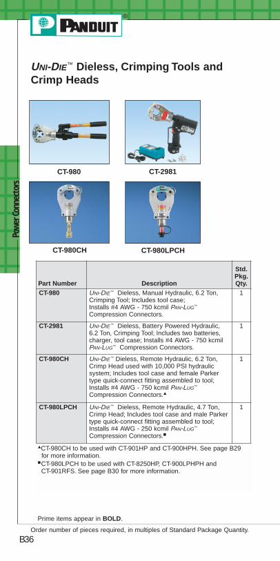
Pow
er C
onne
ctor
s
B36
Prime items appear in BOLD.
Order number of pieces required, in multiples of Standard Package Quantity.
UNI-DIE™ Dieless, Crimping Tools andCrimp Heads
CT-980 CT-2981
CT-980CH CT-980LPCH
Part Number Description
Std.Pkg.Qty.
CT-980 UNI-DIE ™ Dieless, Manual Hydraulic, 6.2 Ton,Crimping Tool; Includes tool case;Installs #4 AWG - 750 kcmil PAN-LUG™
Compression Connectors.
1
CT-2981 UNI-DIE ™ Dieless, Battery Powered Hydraulic,6.2 Ton, Crimping Tool; Includes two batteries,charger, tool case; Installs #4 AWG - 750 kcmilPAN-LUG™ Compression Connectors.
1
CT-980CH UNI-DIE ™ Dieless, Remote Hydraulic, 6.2 Ton,Crimp Head used with 10,000 PSI hydraulicsystem; Includes tool case and female Parkertype quick-connect fitting assembled to tool;Installs #4 AWG - 750 kcmil PAN-LUG™
Compression Connectors.▲
1
CT-980LPCH UNI-DIE ™ Dieless, Remote Hydraulic, 4.7 Ton,Crimp Head; Includes tool case and male Parkertype quick-connect fitting assembled to tool;Installs #4 AWG - 250 kcmil PAN-LUG™
Compression Connectors.■
1
▲CT-980CH to be used with CT-901HP and CT-900HPH. See page B29for more information.
■CT-980LPCH to be used with CT-8250HP, CT-900LPHPH andCT-901RFS. See page B30 for more information.

Prime items appear in BOLD.
Power Connectors
B37For service and technical support, call 800-777-3300
or visit www.panduit.com.
Pressure Gauges
CG-920 CG-940
CG-980 PG-1
Part Number Description
Std.Pkg.Qty.
CG-920 Compression Gauge; Used to measure crimpingforce generated by PANDUIT crimping tools:CT-930, CT-930CH, CT-930LPCH, CT-2930and CT-2931; Includes blank die set andstorage case.
1
CG-940 Compression Gauge; Used to measure outputforce generated by PANDUIT crimping tools:CT-940CH and CT-2940; Includes blank die setand storage case.
1
CG-980 Compression Gauge; Used to insure propercompression force for UNI-DIE ™ DielessCrimping Tools: CT-980, CT-980CH, CT-2980and CT-2981; Includes fixture for mountinggauge in crimping tool and storage case.
1
PG-1 In-Line Pressure Gauge; Provides visualverification of hydraulic output pressure whenused with CT-930LPCH and CT-980LPCH crimpheads, CT-8250HP pump and CT-900LPHPHhose; Includes storage case.
1
PG-1SC In-Line Pressure Gauge provides visualidentification of hydraulic output pressurewhen used with PANDUIT CT-8250HP pumpand CT-900LPHPH hose; Includes steelstorage case.
1

Pow
er C
onne
ctor
s
B38
Features and Benefits – PAN-LUG™
Compression Connectors
Copper Lugs
Bolded features are unique to PANDUIT.
Aluminum Lugs
Color coded bands forproper die selectionand crimp placement
Inspection windowsavailable toassure completeconductor insertion
Part number, studsize and conductorsize marked on partfor easy identification
Easy-to-read, colorcoded die index numbersfor PANDUIT andspecified competitorcrimping diesfor selection
Internally beveled barrelend for easy conductorinsertion (types LCCF andLCAF available with flaredentry for flex conductor)
Made from seamless,high conductivity coppertubing and electro tinplated and burnished toinhibit corrosion
Factory pre-filledwith oxide inhibitorto prevent oxidation
Part number and conductor sizemarked on part foreasy identification
Easy-to-readdie index numbersfor PANDUIT andspecified competitorcrimping diesfor selection
Color codedend plugs for properdie selection
Crimping areasmarked on partfor propercrimp placement
Made from seamlesswrought aluminum andelectro tin plated toinhibit corrosion

Power Connectors
B39For service and technical support, call 800-777-3300
or visit www.panduit.com.
Features and Benefits – PAN-LUG™
Compression Connectors (continued)Copper HTAPs
Part number and agencylistings marked on partfor easy identification
Conductor sizes foreach tap pocketmarked on part Made from high
conductivity copperand electro tin platedto inhibit corrosion
Slotted design toreduce installationtime when usedwith PANDUIT cableties (included)
Easy-to-read,color coded die index numberfor PANDUITcrimping dies,legible after crimping,for selection
Clear Covers for Copper HTAPs
*Labels shown printed with PANDUIT LS7 Printer.
Retainer clips to hold labels insidecover*. Retainer clips have a write-on surface for manual marking
Optically clear to allow360° inspections
Made from highimpact strength self-extinguishingplastic with UL94V-0flammability ratingand minimumoxygen index of 28
Built-in flangesretain HTAP in cover
Easy to assemblesnap-on design
Flexible fingers closely conform to conductor preventing foreign objectsfrom entering cover
Corresponding PANDUIT HTAPpart number,voltage rating andtemperature ratingmolded intocover half foreasy identification
Low profiledesign minimizesspace requirements
Molded in flash barriers protect against electrical flash over
Copper In-Line Reducing Splices
Internally beveled barrel endfor easy conductor insertion
Color coded for properdie selection
Inspection windowsto assure completeconductor insertion
Crimping areas markedon each barrel for propercrimp placement
Compact size provideslow profile installation
Easy-to-read, color codeddie index numbers forPANDUIT and specifiedcompetitor crimping diesfor selection
Made from seamless, highconductivity copper tubing and electro tin plated andburnished to inhibit corrosion
Part number and conductorsize and type marked onpart for easy identification

Pow
er C
onne
ctor
s
B40
Prime items appear in BOLD.
Order number of pieces required, in multiples of Standard Package Quantity.
Code Conductor, One-Hole, Short Barrelwith Window Lug
Part Number Copper Conductor Size
Stud HoleSize(In.)
Std.Pkg.Qty.
LCAS8-10-L
#8 AWG
#10 50
LCAS8-14-L 1/4 50
LCAS8-56-L 5/16 50
LCAS8-38-L 3/8 50
LCAS6-10-L
#6 AWG
#10 50
LCAS6-14-L 1/4 50
LCAS6-56-L 5/16 50
LCAS6-38-L 3/8 50
LCAS4-10-L
#4 AWG
#10 50
LCAS4-14-L 1/4 50
LCAS4-56-L 5/16 50
LCAS4-38-L 3/8 50
LCAS2-14-Q
#2 AWG
1/4 25
LCAS2-56-Q 5/16 25
LCAS2-38-Q 3/8 25
LCAS1-14-E
#1 AWG
1/4 20
LCAS1-56-E 5/16 20
LCAS1-38-E 3/8 20
LCAS1/0-38-X 1/0 AWG 3/8 10
LCAS2/0-14-X
2/0 AWG
1/4 10
LCAS2/0-38-X 3/8 10
LCAS2/0-12-X 1/2 10
LCAS3/0-38-X 3/0 AWG 3/8 10
LCAS4/0-38-X4/0 AWG
3/8 10
LCAS4/0-12-X 1/2 10
LCAS250-12-X 250 kcmil 1/2 10
For 45° and 90° bent lugs available as standard parts and complete tooland die information, see the Electrical Solutions Catalog, SA-ELCB03, atwww.panduit.com.
Type LCAS• For use with stranded copper conductors
• UL Listed and CSA Certified when crimpedwith PANDUIT and specified competitorcrimping tools and dies
• Tested by Telcordia – meetsNEBS Level 3
PAN-LUG™ Copper Compression Connectors

Prime items appear in BOLD.
Power Connectors
B41For service and technical support, call 800-777-3300
or visit www.panduit.com.
Code Conductor, One-Hole, StandardBarrel with Window Lug
Part Number Copper Conductor Size
Stud HoleSize(In.)
Std.Pkg.Qty.
LCA8-10-L
#8 AWG
#10 50
LCA8-14-L 1/4 50
LCA8-56-L 5/16 50
LCA8-38-L 3/8 50
LCA6-10-L
#6 AWG
#10 50
LCA6-14-L 1/4 50
LCA6-56-L 5/16 50
LCA6-38-L 3/8 50
LCA4-14-L
#4 – #3 AWG STR, #2 AWG SOL
1/4 50
LCA4-56-L 5/16 50
LCA4-38-L 3/8 50
LCA2-14-Q
#2 AWG
1/4 25
LCA2-56-Q 5/16 25
LCA2-38-Q 3/8 25
LCA2-12-Q 1/2 25
LCA1-14-E
#1 AWG
1/4 20
LCA1-56-E 5/16 20
LCA1-38-E 3/8 20
LCA1-12-E 1/2 20
LCA1/0-14-X
1/0 AWG
1/4 10
LCA1/0-56-X 5/16 10
LCA1/0-38-X 3/8 10
LCA1/0-12-X 1/2 10
LCA2/0-14-X
2/0 AWG
1/4 10
LCA2/0-56-X 5/16 10
LCA2/0-38-X 3/8 10
LCA2/0-12-X 1/2 10
Type LCA
• For use with stranded copper conductors
• UL Listed and CSA Certified when crimpedwith PANDUIT and specified competitorcrimping tools and dies
• Tested by Telcordia – meetsNEBS Level 3
For 45° and 90° bent lugs available as standard parts and complete tooland die information, see the Electrical Solutions Catalog, SA-ELCB03, atwww.panduit.com.
continued on page B42

LCA3/0-14-X
3/0 AWG
1/4 10
LCA3/0-56-X 5/16 10
LCA3/0-38-X 3/8 10
LCA3/0-12-X 1/2 10
LCA4/0-56-X
4/0 AWG
5/16 10
LCA4/0-38-X 3/8 10
LCA4/0-12-X 1/2 10
LCA250-56-X
250 kcmil
5/16 10
LCA250-38-X 3/8 10
LCA250-12-X 1/2 10
LCA300-12-X 300 kcmil 1/2 10
LCA350-38-X350 kcmil
3/8 10
LCA350-12-X 1/2 10
LCA400-12-6 400 kcmil 1/2 6
LCA500-12-6 500 kcmil 1/2 6
LCA600-12-6 600 kcmil 1/2 6
Pow
er C
onne
ctor
s
B42Order number of pieces required, in multiples of Standard Package Quantity.
Prime items appear in BOLD.
Code Conductor, One-Hole, StandardBarrel with Window Lug (continued)
Part Number Copper Conductor Size
Stud HoleSize(In.)
Std.Pkg.Qty.
For 45° and 90° bent lugs available as standard parts and complete tooland die information, see the Electrical Solutions Catalog, SA-ELCB03, atwww.panduit.com.
Type LCA
• For use with stranded copper conductors
• UL Listed and CSA Certified when crimpedwith PANDUIT and specified competitorcrimping tools and dies
• Tested by Telcordia – meetsNEBS Level 3

Prime items appear in BOLD.
Power Connectors
B43For service and technical support, call 800-777-3300
or visit www.panduit.com.
Code Conductor, One-Hole, LongBarrel Lug
• For use with stranded copper conductors
• UL Listed and CSA Certified when crimpedwith PANDUIT and specified competitorcrimping tools and dies
• Tested by Telcordia – meets NEBSLevel 3
Part Number Copper Conductor Size
Stud Hole Size(In.)
Std.Pkg.Qty.
LCB8-14-L #8 AWG 1/4 50
LCB6-14-L#6 AWG
1/4 50
LCB6-38-L 3/8 50
LCB4-14-L #4 – 3 AWG STR, #2 AWG SOL 1/4 50
LCB2-56-Q #2 AWG 5/16 25
LCB1-56-E #1 AWG 5/16 20
LCB1/0-38-X 1/0 AWG 3/8 10
LCB2/0-38-X2/0 AWG
3/8 10
LCB2/0-12-X 1/2 10
LCB3/0-38-X3/0 AWG
3/8 10
LCB3/0-12-X 1/2 10
LCB4/0-38-X4/0 AWG
3/8 10
LCB4/0-12-X 1/2 10
LCB250-12-X 250 kcmil 1/2 10
LCB350-12-X 350 kcmil 1/2 10
LCB500-12-6 500 kcmil 1/2 6
Type LCB
For 45° and 90° bent lugs available as standard parts and complete tooland die information, see the Electrical Solutions Catalog, SA-ELCB03, atwww.panduit.com.

Pow
er C
onne
ctor
s
B44
Prime items appear in BOLD.
Order number of pieces required, in multiples of Standard Package Quantity.
Type LCD
For 45° and 90° bent lugs available as standard parts and complete tooland die information, see the Electrical Solutions Catalog, SA-ELCB03, atwww.panduit.com.
Code Conductor, Two-Hole, StandardBarrel with Window Lug
• For use with stranded copper conductors
• UL Listed and CSA Certified when crimpedwith PANDUIT and specified competitorcrimping tools and dies
• Tested by Telcordia – meetsNEBS Level 3
Part NumberCopper Conductor
Size
Stud HoleSize(In.)
Stud HoleSpacing
(In.)
Std.Pkg.Qty.
LCD8-10A-L
#8 AWG
#10 .63 50
LCD8-14A-L 1/4 .63 50
LCD8-14B-L 1/4 .75 50
LCD8-14D-L 1/4 1.00 50
LCD6-10A-L
#6 AWG
#10 .63 50
LCD6-14A-L 1/4 .63 50
LCD6-14B-L 1/4 .75 50
LCD6-14D-L 1/4 1.00 50
LCD6-38D-L 3/8 1.00 50
LCD4-14A-L
#4 – #3 AWG STR,#2 AWG SOL
1/4 .63 50
LCD4-14B-L 1/4 .75 50
LCD4-14D-L 1/4 1.00 50
LCD4-38D-L 3/8 1.00 50
LCD2-14A-Q
#2 AWG
1/4 .63 25
LCD2-14B-Q 1/4 .75 25
LCD2-14D-Q 1/4 1.00 25
LCD2-38D-Q 3/8 1.00 25
LCD1-14A-E#1 AWG
1/4 .63 20
LCD1-38D-E 3/8 1.00 20
LCD1/0-38D-X 1/0 AWG 3/8 1.00 10
LCD2/0-14B-X2/0 AWG
1/4 .75 10
LCD2/0-38D-X 3/8 1.00 10
LCD3/0-38D-X 3/0 AWG 3/8 1.00 10
LCD4/0-38D-X 4/0 AWG 3/8 1.00 10
LCD250-38D-X 250 kcmil 3/8 1.00 10

Prime items appear in BOLD.
Power Connectors
B45For service and technical support, call 800-777-3300
or visit www.panduit.com.
Code Conductor, Two-Hole, LongBarrel Lug
• For use with stranded copper conductors
• UL Listed and CSA Certified whencrimped with PANDUIT and specifiedcompetitor crimping tools and dies
• Tested by Telcordia – meetsNEBS Level 3
Type LCC
For 45° and 90° bent lugs available as standard parts and complete tooland die information, see the Electrical Solutions Catalog, SA-ELCB03, atwww.panduit.com.◆NEMA hole sizes and spacing.
Part NumberCopper Conductor
Size
Stud Hole Size(In.)
Stud HoleSpacing
(In.)
Std.Pkg.Qty.
LCC8-14A-L #8 AWG 1/4 .63 50
LCC6-14A-L
#6 AWG
1/4 .63 50
LCC6-14B-L 1/4 .75 50
LCC6-38D-L 3/8 1.00 50
LCC4-14A-L #4 – #3 AWG STR,#2 AWG SOL
1/4 .63 50
LCC2-56B-Q
#2 AWG
5/16 .75 25
LCC2-38D-Q 3/8 1.00 25
LCC2-38-Q 3/8 1.75 25
LCC2-12-Q 1/2 1.75 25
LCC1-14A-E #1 AWG 1/4 .63 20
LCC1/0-12-X 1/0 AWG 1/2 1.75 10
LCC2/0-38D-X2/0 AWG
3/8 1.00 10
LCC2/0-12-X 1/2 1.75 10
LCC3/0-12-X 3/0 AWG 1/2 1.75 10
LCC4/0-12-X◆ 4/0 AWG 1/2 1.75 10
LCC250-12-X◆ 250 kcmil 1/2 1.75 10
LCC300-12-X◆ 300 kcmil 1/2 1.75 10
LCC350-12-X◆ 350 kcmil 1/2 1.75 10
LCC400-12-6◆ 400 kcmil 1/2 1.75 6
LCC500-12-6◆ 500 kcmil 1/2 1.75 6
LCC600-12-6◆ 600 kcmil 1/2 1.75 6
LCC750-12-6◆ 750 kcmil 1/2 1.75 6

Pow
er C
onne
ctor
s
B46
Prime items appear in BOLD.
Order number of pieces required, in multiples of Standard Package Quantity.
Type SCS
For complete tool and die information, see the Electrical SolutionsCatalog, SA-ELCB03, at www.panduit.com.
Code Conductor, Standard Barrel,Butt Splice
• For use with stranded copper conductors
• UL Listed and CSA Certified whencrimped with PANDUIT and specifiedcompetitor crimping tools and dies
• Tested by Telcordia – meetsNEBS Level 3
Part Number Copper Conductor SizeLength
(In.)
Std.Pkg.Qty.
SCS8-L #8 AWG 1.50 50
SCS6-L #6 AWG 1.75 50
SCS4-L #4 – #3 AWG STR,#2 AWG SOL
1.75 50
SCS2-Q #2 AWG 1.87 25
SCS1-E #1 AWG 1.87 20
SCS1/0-X 1/0 AWG 1.87 10
SCS2/0-X 2/0 AWG 2.00 10
SCS3/0-X 3/0 AWG 2.12 10
SCS4/0-X 4/0 AWG 2.12 10
SCS250-X 250 kcmil 2.25 10
SCS350-X 350 kcmil 2.37 10
SCS500-6 500 kcmil 2.87 6
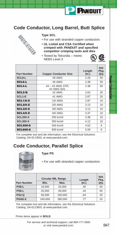
Prime items appear in BOLD.
Power Connectors
B47For service and technical support, call 800-777-3300
or visit www.panduit.com.
Code Conductor, Long Barrel, Butt Splice
• For use with stranded copper conductors
• UL Listed and CSA Certified whencrimped with PANDUIT and specifiedcompetitor crimping tools and dies
• Tested by Telcordia – meetsNEBS Level 3
Part Number Copper Conductor SizeLength
(In.)
Std.Pkg.Qty.
SCL8-L #8 AWG 2.25 50
SCL6-L #6 AWG 2.38 50
SCL4-L #4 – #3 AWG STR,#2 AWG SOL
2.38 50
SCL2-Q #2 AWG 2.62 25
SCL1-E #1 AWG 2.87 20
SCL1/0-X 1/0 AWG 2.87 10
SCL2/0-X 2/0 AWG 3.13 10
SCL3/0-X 3/0 AWG 3.12 10
SCL4/0-X 4/0 AWG 3.37 10
SCL250-X 250 kcmil 3.38 10
SCL350-X 350 kcmil 4.12 10
SCL500-6 500 kcmil 4.62 6
SCL600-6 600 kcmil 5.50 6
Type SCL
Type PS
Code Conductor, Parallel Splice
• For use with stranded copper conductors
Part Number
Circular MIL Range Length(In.)
Std.Pkg.Qty.Min. Max.
PS8-L 19,000 25,000 .40 50
PS6-L 25,000 40,000 .44 50
PS2-Q 65,000 100,000 .64 25
PS4/0-X 240,000 280,000 .77 10
For complete tool and die information, see the Electrical SolutionsCatalog, SA-ELCB03, at www.panduit.com.
For complete tool and die information, see the Electrical SolutionsCatalog, SA-ELCB03, at www.panduit.com.

Pow
er C
onne
ctor
s
B48
Prime items appear in BOLD.
Order number of pieces required, in multiples of Standard Package Quantity.
Type LCAX
Flex Conductor, One-Hole, StandardBarrel with Window Lug
• For use with flexible and extra-flexiblecopper conductors
• For use with code stranded copper conductorsup to 4/0 AWG
• UL Listed and CSA Certified when crimpedwith PANDUIT and specified competitorcrimping tools and dies
Part Number
Flex Conductor SizeStud Hole
Size (In.)
Std.Pkg.Qty.
ClassG, H, I, K, M Locomotive
LCAX8-10-L
#8 AWG #8 AWG
#10 50
LCAX8-14-L 1/4 50
LCAX8-56-L 5/16 50
LCAX8-38-L 3/8 50
LCAX6-10-L
#6 AWG #6 AWG
#10 50
LCAX6-14-L 1/4 50
LCAX6-56-L 5/16 50
LCAX6-38-L 3/8 50
LCAX4-14-L
#4 AWG #5, #4, #3 AWG
1/4 50
LCAX4-56-L 5/16 50
LCAX4-38-L 3/8 50
LCAX2-14-E
#2 AWG #2 AWG
1/4 20
LCAX2-56-E 5/16 20
LCAX2-38-E 3/8 20
LCAX2-12-E 1/2 20
LCAX1-14-X
#1 AWG #1 AWG
1/4 10
LCAX1-56-X 5/16 10
LCAX1-38-X 3/8 10
LCAX1-12-X 1/2 10
LCAX1/0-14-X
1/0 AWG 1/0 AWG
1/4 10
LCAX1/0-56-X 5/16 10
LCAX1/0-38-X 3/8 10
LCAX1/0-12-X 1/2 10
For 45° and 90° bent lugs available as standard parts and complete tooland die information, see the Electrical Solutions Catalog, SA-ELCB03, atwww.panduit.com

Prime items appear in BOLD.
Power Connectors
B49For service and technical support, call 800-777-3300
or visit www.panduit.com.
LCAX2/0-14-X
2/0 AWG 2/0 AWG
1/4 10
LCAX2/0-56-X 5/16 10
LCAX2/0-38-X 3/8 10
LCAX2/0-12-X 1/2 10
LCAX3/0-14-X
3/0 AWG 3/0 AWG
1/4 10
LCAX3/0-56-X 5/16 10
LCAX3/0-38-X 3/8 10
LCAX3/0-12-X 1/2 10
LCAX4/0-56-X
4/0 AWG 4/0 AWG
5/16 10
LCAX4/0-38-X 3/8 10
LCAX4/0-12-X 1/2 10
LCAX250-56-X
250 kcmil 262.6 kcmil
5/16 10
LCAX250-38-X 3/8 10
LCAX250-12-X 1/2 10
LCAX300-12-6 300 kcmil 313.1 kcmil 1/2 6
LCAX350-38-6350 kcmil 373.7 kcmil
3/8 6
LCAX350-12-6 1/2 6
LCAX500-12-6 500 kcmil 535.3 kcmil 1/2 6
Part Number
Flex Conductor SizeStud Hole
Size (In.)
Std.Pkg.Qty.
ClassG, H, I, K, M Locomotive
Flex Conductor, One-Hole, StandardBarrel with Window Lug (continued)
Type LCAX
• For use with flexible and extra-flexiblecopper conductors
• For use with code stranded copper conductorsup to 4/0 AWG
• UL Listed and CSA Certified when crimpedwith PANDUIT and specified competitorcrimping tools and dies
For 45° and 90° bent lugs available as standard parts and complete tooland die information, see the Electrical Solutions Catalog, SA-ELCB03, atwww.panduit.com.

Pow
er C
onne
ctor
s
B50
Prime items appear in BOLD.
Order number of pieces required, in multiples of Standard Package Quantity.
For 45° and 90° bent lugs available as standard parts and complete tooland die information, see the Electrical Solutions Catalog, SA-ELCB03, atwww.panduit.com.
Flex Conductor, One-Hole, StandardBarrel with Window, Flared Lug
• For use with flexible and extra-flexiblecopper conductors
• Tested by Telcordia – meets NEBS Level 3
Type LCAF
Part Number
Flex Conductor SizeStud Hole
Size(In.)
Std.Pkg.Qty.Class K & M Locomotive
LCAF6-14-L#6 AWG #6 AWG
1/4 50
LCAF6-38-L 3/8 50
LCAF4-14-L#4 AWG #4 AWG
1/4 50
LCAF4-38-L 3/8 50
LCAF2-14-E#2 AWG #2 AWG
1/4 20
LCAF2-38-E 3/8 20
LCAF1-38-X #1 AWG #1 AWG 3/8 10
LCAF1/0-14-X
1/0 AWG 1/0 AWG
1/4 10
LCAF1/0-56-X 5/16 10
LCAF1/0-38-X 3/8 10
LCAF1/0-12-X 1/2 10
LCAF2/0-38-X2/0 AWG 2/0 AWG
3/8 10
LCAF2/0-12-X 1/2 10
LCAF3/0-38-X3/0 AWG 3/0 AWG
3/8 10
LCAF3/0-12-X 1/2 10
LCAF4/0-38-X4/0 AWG 4/0 AWG
3/8 10
LCAF4/0-12-X 1/2 10
LCAF250-12-X 250 kcmil 262.6 kcmil 1/2 10
LCAF350-12-6 350 kcmil 373.7 kcmil 1/2 6
LCAF400-12-6 400 kcmil 444.4 kcmil 1/2 6
LCAF600-12-6 — 646.4 kcmil 1/2 6

Prime items appear in BOLD.
Power Connectors
B51For service and technical support, call 800-777-3300
or visit www.panduit.com.
Flex Conductor, One-Hole, Long Barrelwith Window Lug
• For use with flexible and extra-flexiblecopper conductors
• For use with code stranded copper conductorsup to 4/0 AWG
• UL Listed and CSA Certified when crimpedwith PANDUIT and specified competitorcrimping tools and dies
Part Number
Flex Conductor Size
Stud HoleSize(In.)
Std.Pkg.Qty.
ClassG, H, I, K, M Locomotive
LCBX8-14-L #8 AWG #8 AWG 1/4 50
LCBX6-14-L#6 AWG #6 AWG
1/4 50
LCBX6-38-L 3/8 50
LCBX4-14-L #4 AWG #5, #4, #3 AWG 1/4 50
LCBX1-56-X #1 AWG #1 AWG 5/16 10
LCBX1/0-38-X 1/0 AWG 1/0 AWG 3/8 10
LCBX2/0-38-X2/0 AWG 2/0 AWG
3/8 10
LCBX2/0-12-X 1/2 10
LCBX3/0-38-X 3/0 AWG 3/0 AWG 3/8 10
LCBX4/0-38-X4/0 AWG 4/0 AWG
3/8 10
LCBX4/0-12-X 1/2 10
LCBX350-12-6 350 kcmil 373.7 kcmil 1/2 6
LCBX500-12-6 500 kcmil 535.3 kcmil 1/2 6
Type LCBX
For 45° and 90° bent lugs available as standard parts and complete tooland die information, see the Electrical Solutions Catalog, SA-ELCB03, atwww.panduit.com.

Pow
er C
onne
ctor
s
B52
Prime items appear in BOLD.
Order number of pieces required, in multiples of Standard Package Quantity.
Type LCDX
For 45° and 90° bent lugs available as standard parts and complete tooland die information, see the Electrical Solutions Catalog, SA-ELCB03, atwww.panduit.com.◆NEMA hole sizes and spacing.
Flex Conductor, Two-Hole, StandardBarrel with Window Lug
• For use with flexible and extra-flexiblecopper conductors
• For use with code stranded copper conductorsup to 4/0 AWG
• UL Listed and CSA Certified when crimpedwith PANDUIT and specifiedcompetitor crimping toolsand dies
Part Number
Flex Conductor Size Stud Hole Size(In.)
Std.Pkg.Qty.
ClassG, H, I, K, M Locomotive
LCDX8-10A-L
#8 AWG #8 AWG
#10 50
LCDX8-14A-L 1/4 50
LCDX8-14B-L 1/4 50
LCDX8-14D-L 1/4 50
LCDX6-10A-L
#6 AWG #6 AWG
#10 50
LCDX6-14A-L 1/4 50
LCDX6-14B-L 1/4 50
LCDX6-14D-L 1/4 50
LCDX6-38D-L 3/8 50
LCDX4-14A-L
#4 AWG #5, #4, #3 AWG
1/4 50
LCDX4-14B-L 1/4 50
LCDX4-14D-L 1/4 50
LCDX4-38D-L 3/8 50
LCDX2-14A-E
#2 AWG #2 AWG
1/4 20
LCDX2-14B-E 1/4 20
LCDX2-14D-E 1/4 20
LCDX2-38D-E 3/8 20
LCDX1-14A-X#1 AWG #1 AWG
1/4 10
LCDX1-38D-X 3/8 10
LCDX1/0-38D-X 1/0 AWG 1/0 AWG 3/8 10
LCDX2/0-14B-X2/0 AWG 2/0 AWG
1/4 10
LCDX2/0-38D-X 3/8 10
LCDX3/0-38D-X 3/0 AWG 3/0 AWG 3/8 10
LCDX3/0-12-X◆ 3/0 AWG 3/0 AWG 1/2 10
LCDX4/0-38D-X 4/0 AWG 4/0 AWG 3/8 10
LCDX250-38D-X250 kcmil 262.6 kcmil
3/8 10
LCDX250-12-X◆ 1/2 10
LCDX300-12-6◆ 300 kcmil 313.1 kcmil 1/2 6
LCDX600-12-6◆ 600 kcmil — 1/2 6
LCDX750-12-3◆ — 777.7 kcmil 1/2 3
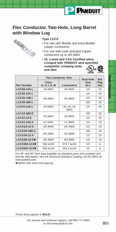
Prime items appear in BOLD.
Power Connectors
B53For service and technical support, call 800-777-3300
or visit www.panduit.com.
Flex Conductor, Two-Hole, Long Barrelwith Window Lug
• For use with flexible and extra-flexiblecopper conductors
• For use with code stranded copperconductors up to 4/0 AWG
• UL Listed and CSA Certified whencrimped with PANDUIT and specifiedcompetitor crimping toolsand dies
Type LCCX
For 45° and 90° bent lugs available as standard parts and complete tooland die information, see the Electrical Solutions Catalog, SA-ELCB03, atwww.panduit.com.◆NEMA hole sizes and spacing.
Part Number
Flex Conductor SizeStud Hole
Size(In.)
Std.Pkg.Qty.
ClassG, H, I, K, M Locomotive
LCCX8-14A-L #8 AWG #8 AWG 1/4 50
LCCX6-14A-L
#6 AWG #6 AWG
1/4 50
LCCX6-14B-L 1/4 50
LCCX6-38D-L 3/8 50
LCCX4-14A-L #4 AWG #5, #4, #3AWG
1/4 50
LCCX2-38D-E#2 AWG #2 AWG
3/8 20
LCCX2-12-E 1/2 20
LCCX1-14A-X #1 AWG #1 AWG 1/4 10
LCCX1/0-12-X 1/0 AWG 1/0 AWG 1/2 10
LCCX2/0-38D-X2/0 AWG 2/0 AWG
3/8 10
LCCX2/0-12-X 1/2 10
LCCX4/0-12-X◆◆ 4/0 AWG 4/0 AWG 1/2 10
LCCX350-12-6◆◆ 350 kcmil 373.7 kcmil 1/2 6
LCCX500-12-6◆◆ 500 kcmil 535.3 kcmil 1/2 6

Technical Information
C1For service and technical support, call 800-777-3300
or visit www.panduit.com.
Technical Specification andSelection Information
PANDUIT Terminal Approvals
Logo(Symbol) Agency Spec/Approval Requirement
ApplicableProducts
UnderwritersLaboratories,Inc.
#E52164 – UL486A
Minimum TensileStrength (Pull outforce for the crimpterminal) and testcurrent for Max.50°C Rise (Amps)
All Ring andForkTerminals
#E78522 – UL310
Minimum TensileStrength (Pull outforce for the crimpterminal) andcontinuous testcurrent for Max.30°C Rise (Amps)(for .187", .205",.250" tab widths)and (.110"tab width)
AllDisconnects
#E52164 – UL486C
Minimum TensileStrength (Pull outforce for the crimpterminal) and testcurrent for Max.50°C Rise (Amps)
All Splices
CanadianStandardsAssociation
#LR31212 – C22.2 No. 65Minimum TensileStrength (Pull outforce for the crimpterminal) and testcurrent for Max.50°C Rise (Amps)
All Ring andForkTerminals
#LR31212 – C22.2 No. 153 AllDisconnects

Tech
nica
l Inf
orm
atio
n
C2
Applicable PAN-TERM ® products meet or exceedthe following test specifications:
• UL486A (Terminals)• UL486C (Splices)• UL310 (Blade Adapters)• CSA C22.2 No. 65 (all designs)
UL and CSA approved products are shown with the applicable logos in the product section.UL file #E52164, CSA File #LR31212
Applicable PAN-TERM ® products meet or exceedthe following test specifications:
• UL310 (Disconnects)• CSA C22.2 No. 153 (all designs)
UL and CSA Listed products are shown with the applicable logos in the product section.UL file #E78522 and CSA file #LR31212.
*Pull-out force of the crimped disconnect.
Performance Requirements
Wire Size (AWG)#26 #24 #22 #20 #18 #16 #14 #12 #10
UL 486A (TERMINALS), UL310 (MALE BLADE ADAPTERS)Test Current for Max. 50°CRise (Amps) 3.5 7 9 12 17 18 30 35 50
Min. Tensile Strength* (Lbs.) 3 5 8 13 20 30 50 70 80
UL 486C (SPLICES)Test Current for Max. 50°CRise (Amps) 5.5 7 9 12 17 18 30 35 50
Min. Tensile Strength* (Lbs.) 3 5 8 10 10 15 25 35 40
*Pull-out force of the crimped terminal
Wire Size (AWG)
#22 #20 #18 #16 *#14 #12 #10
UL310 (DISCONNECTS)Continuous Test Current for Max.30°C Rise (amps)(for 187", 205", 250" tab widths)
3 4 7 10 15 20 24
Continuous Test Current for Max.30°C Rise (amps)(for .110", tab width)
2 3 4 5 NotApplicable
Min. Tensile Strength* (Lbs.) 8 13 20 30 50 70 80
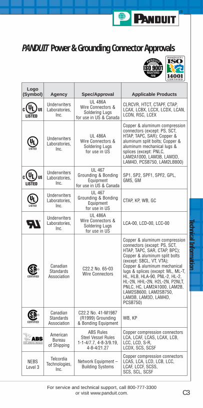
Logo (Symbol) Agency Spec/Approval Applicable Products
UnderwritersLaboratories,
Inc.
UL 486AWire Connectors &
Soldering Lugsfor use in US & Canada
CLRCVR, HTCT, CTAPF, CTAP,LCAX, LCBX, LCCX, LCDX, LCAN,LCDN, RSC, LCEX
UnderwritersLaboratories,
Inc.
UL 486AWire Connectors &
Soldering Lugsfor use in US
Copper & aluminum compressionconnectors (except: PS, SCT,HTAP, TAPC, SAR); Copper &aluminum split bolts; Copper &aluminum mechanical lugs &splices (except: PNLC,LAM2A1000, LAM3B, LAM3D,LAM4D, PCSB750, LAM2LB800)
UnderwritersLaboratories,
Inc.
UL 467Grounding & Bonding
Equipmentfor use in US & Canada
SP1, SP2, SPF1, SPF2, GPL,GMS, GM
UnderwritersLaboratories,
Inc.
UL 467Grounding & Bonding
Equipmentfor use in US
CTAP, KP, WB, GC
UnderwritersLaboratories,
Inc.
UL 486AWire Connectors &
Soldering Lugsfor use in US
LCA-00, LCD-00, LCC-00
CanadianStandards
Association
C22.2 No. 65-03Wire Connectors
Copper & aluminum compressionconnectors (except: PS, SCT,HTAP, TAPC, SAR, CTAP, BPC);Copper & aluminum split bolts(except: SBCL, VT, VTA);Copper & aluminum mechanicallugs & splices (except: ML, ML-T,HL, HLB, HLA-90, PNL-2, HL-2,HL-2N, HHL-2N, H2L-2N, P2NLT,PNLC, HC, LAM2A1000, LAM2B,LAM2SB600, LAM2SB750,LAM3B, LAM3D, LAM4D,PCSB750)
CanadianStandards
Association
C22.2 No. 41-M1987(R1999) Grounding
& Bonding EquipmentWB, KP
AmericanBureau
of Shipping
ABS RulesSteel Vessel Rules
1-1-4/7.7, 4-8-3/9.19,4-8-4/21.27
Copper compression connectorsLCA, LCAF, LCAS, LCAX, LCB,LCC, LCD, S-R,LCDX, SCS, SCSF
NEBSLevel 3
TelcordiaTechnologies,
Inc.
Network Equipment –Building Systems
Copper compression connectorsLCAS, LCA, LCD, LCB, LCC,LCAF, LCCF, SCSS,SCS, SCL, SCSF
Technical Information
C3For service and technical support, call 800-777-3300
or visit www.panduit.com.
PANDUIT Power & Grounding Connector Approvals

Tech
nica
l Inf
orm
atio
n
C4
Equivalent TablesFractional Inches/Decimal Inches/Millimeters
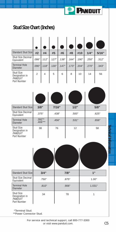
Technical Information
C5For service and technical support, call 800-777-3300
or visit www.panduit.com.
Stud Size Chart (Inches)
*Terminal Stud.**Power Connector Stud.
Standard Stud Size
Stud Size DecimalEquivalent
Terminal HoleDiameter
Stud SizeDesignation inPANDUITPart Number
3/4" 7/8" 1"
.750" .875" 1.00"
.810" .906" 1.031"
34 78 1
#2 #4 #5 #6 #8 #10 1/4" 5/16"
.086" .112" .127" .138" .164" .190" .250" .312"
.090" .118" .130" .147" .173" .204" .270" .343"
2 4 5 6 8 10 14 56
Standard Stud Size
Stud Size DecimalEquivalent
Terminal HoleDiameter
Stud SizeDesignation inPANDUITPart Number
3/8" 7/16" 1/2" 5/8"
.375" .438" .500" .625"
.392"* .456" .531" .656"
.406"**
38 76 12 58
Standard Stud Size
Stud Size DecimalEquivalent
Terminal HoleDiameter
Stud SizeDesignation inPANDUITPart Number

Tech
nica
l Inf
orm
atio
n
C6
Common Conductor Sizes and StrandingsReference Chart
*Strandings required for UL and CSA Certification testing.
ConductorIndividual Strands Overall Conductor Size
No.
Diameter Diameter Area
AWGMetricmm2 mm In. mm In.
Circ.MILS
0.05 25 .05 .002 .25 .010 970.06 41 .05 .002 .36 .014 159
26
10 .13 .005 .53 .021 2501 .41 .016 .41 .016 2567 .16 .006 .48 .019 27819 .10 .004 .51 .020 304
24
41 .08 .003 .58 .023 38410 .16 .006 .58 .023 3971 .51 .020 .51 .020 4007 .20 .008 .61 .024 44819 .13 .005 .61 .024 475
0.25
65 .07 .003 .65 .026 484128 .05 .002 .65 .026 49632 .10 .004 .65 .026 49614 .16 .006 .65 .026 556
22
1 .64 .025 .64 .025 62516 .16 .006 .76 .030 63526 .13 .005 .76 .030 6507 .25 .010 .76 .030 70019 .16 .006 .79 .031 754
0.38
48 .10 .004 .80 .031 744194 .05 .002 .80 .031 752100 .07 .003 .80 .031 7607 .27 .011 .80 .031 79112 .21 .008 .80 .031 82021 .16 .006 .80 .031 833
0.57 .30 .012 .90 .035 97716 .20 .008 .90 .035 9921 .80 .031 .80 .031 992
20
*10 .25 .010 .89 .035 10001 .81 .032 .81 .032 102441 .13 .005 .91 .036 102526 .16 .006 91 .036 1032*7 .32 .013 .97 .038 111119 .20 .008 .94 .037 1216
0.757 .37 .015 1.10 .043 148524 .20 .008 1.20 .047 14881 1.00 .039 1.00 .039 1550
18
*16 .25 .010 1.19 .047 16001 1.02 .040 1.02 .040 160065 .13 .005 1.19 .047 162541 .16 .006 1.19 .047 1627*7 .40 .016 1.22 .048 177019 .25 .010 1.24 .049 1900
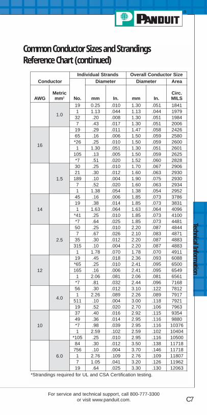
Technical Information
C7For service and technical support, call 800-777-3300
or visit www.panduit.com.
Common Conductor Sizes and StrandingsReference Chart (continued)
ConductorIndividual Strands Overall Conductor Size
No.
Diameter Diameter Area
AWGMetricmm2 mm In. mm In.
Circ.MILS
1.0
19 0.25 .010 1.30 .051 18411 1.13 .044 1.13 .044 197932 .20 .008 1.30 .051 19847 .43 .017 1.30 .051 2006
16
19 .29 .011 1.47 .058 242665 .16 .006 1.50 .059 2580*26 .25 .010 1.50 .059 26001 1.30 .051 1.30 .051 2601
105 .13 .005 1.50 .059 2625*7 .51 .020 1.52 .060 2828
1.5
30 .25 .010 1.70 .067 290621 .30 .012 1.60 .063 2930189 .10 .004 1.90 .075 29307 .52 .020 1.60 .063 29341 1.38 .054 1.38 .054 2952
14
45 .16 .006 1.85 .073 378619 .38 .014 1.85 .073 38311 1.63 .064 1.63 .064 4096
*41 .25 .010 1.85 .073 4100*7 .64 .025 1.85 .073 4481
2.5
50 .25 .010 2.20 .087 48447 .67 .026 2.10 .083 487135 .30 .012 2.20 .087 4883315 .10 .004 2.20 .087 48831 1.78 .070 1.78 .070 4911
12
19 .45 .018 2.36 .093 6088*65 .25 .010 2.41 .095 6500165 .16 .006 2.41 .095 65491 2.06 .081 2.06 .081 6561*7 .81 .032 2.44 .096 7168
4.0
56 .30 .012 3.10 .122 78121 2.26 .089 2.26 .089 7917
511 .10 .004 3.00 .118 792119 .52 .020 2.70 .106 7963
10
37 .40 .016 2.92 .115 935449 .36 .014 2.95 .116 9880*7 .98 .039 2.95 .116 103761 2.59 .102 2.59 .102 10404
*105 .25 .010 2.95 .116 10500
6.0
84 .30 .012 3.50 .138 11718756 .10 .004 3.70 .146 117181 2.76 .109 2.76 .109 118077 1.05 .041 3.20 .126 1196219 .64 .025 3.30 .130 12063
*Strandings required for UL and CSA Certification testing.

Tech
nica
l Inf
orm
atio
n
C8
Common Conductor Sizes and StrandingsReference Chart (continued)
ConductorIndividual Strands Overall Conductor Size
No.
Diameter Diameter Area
AWGMetricmm2 mm In. mm In.
Circ.MILS
67 0.107 0.042 3.21 0.126 11840
1 2.77 0.109 2.77 0.109 11840
97 1.1 0.0432 3.3 0.13 13000
1 2.91 0.1144 2.91 0.114 13090
81 3.26 0.1285 3.25 0.128 16510
7 1.23 0.0486 3.7 0.146 16510
107 1.37 0.054 4.12 0.162 19740
1 3.58 0.141 3.58 0.141 19740
77 1.38 0.0545 4.15 0.164 20520
1 3.67 0.1443 3.67 0.144 20520
67 1.55 0.0612 4.66 0.184 26240
1 4.11 0.162 4.11 0.162 26240
16 7 1.73 0.008 5.13 0.204 31580
5 7 1.75 0.0688 5.24 0.206 33090
4 7 1.96 0.0772 5.88 0.232 41740
257 2.16 0.085 6.48 0.255 49340
19 1.32 0.052 6.6 0.26 49340
3 7 2.2 0.0867 6.61 0.26 52620
2 7 2.47 0.0974 7.42 0.292 66300
357 2.54 0.1 7.62 300 69070
19 1.55 0.001 7.75 0.305 69070
1 19 1.5 0.0064 8.43 0.332 83690
50 19 1.85 0.073 9.27 0.365 98680
1/0 19 1.59 0.0745 9.46 0.373 10500
2/0 19 2.13 0.0837 10.6 0.419 133100
70 19 2.18 0.086 10.9 0.43 138100
3/019 2.59 0.094 11.9 0.47 167800
36 1.71 0.0673 12 0.471 167800
9519 2.57 0.101 12.8 0.505 187500
37 1.83 0.072 12.5 0.504 187500
4/0 19 2.89 0.1055 13.4 0.528 211600

Technical Information
C9For service and technical support, call 800-777-3300
or visit www.panduit.com.
Common Conductor Sizes and StrandingsReference Chart (continued)
ConductorIndividual Strands Overall Conductor Size
No.
Diameter Diameter Area
AWGMetricmm2 mm In. mm In.
Circ.MILS
120 37 2.06 0.081 14.4 0.567 237.8kcmil
250kcmil
37 2.07 0.0822 14.6 0.575 250kcmil
300kcmil
150 37 2.29 0.09 16 0.63 300kcmil
350kcmil
37 2.47 0.0973 17.3 0.681 350kcmil
185 37 2.54 0.1 17.8 0.7 365.1kcmil
400kcmil
37 2.64 0.104 18.5 0.728 400kcmil
240
37 2.9 0.114 20.3 0.798 473.6kcmil
61 2.26 0.089 20.3 0.801 473.6kcmil
500kcmil
37 2.95 0.1162 20.7 0.813 500kcmil
61 2.3 0.0905 20.7 0.814 500kcmil
300kcmil
61 2.51 0.099 22.6 0.891 592.1kcmil
600kcmil
61 2.52 0.0992 22.7 0.893 600kcmil
700kcmil
61 2.72 0.1071 24.5 0.964 700kcmil
750kcmil
61 2.82 0.1109 25.4 0.998 750kcmil
91 2.31 0.0908 25.4 0.998 750kcmil
400 61 2.9 0.114 26.1 1.026 798.4kcmil
800kcmil
61 2.91 0.1145 26.2 1.031 800kcmil
91 2.38 0.0938 26.2 1.032 800kcmil
1000kcmil
500 61 3.25 0.128 28.3 1.152 986.8kcmil
91 2.66 0.1048 29.3 1.153 1000kcmil
625 91 2.97 0.117 32.7 1.287 1233.7kcmil

Index
D1For service and technical support, call 800-777-3300
or visit www.panduit.com.
B
BS10-L...........................A42BS14-C ..........................A42BS18-C ..........................A42BS22-C ..........................A42BSN10-L ........................A41BSN14-C .......................A41BSN18-C .......................A41BSN22-C .......................A41BSV10X-L......................A41BSV14X-C .....................A41BSV18X-CY...................A41
C
C-720.............................B31CC-720 ..........................B31CD-2001-1 .....................B33CD-2001-1/0 ..................B33CD-2001-2 .....................B33CD-2001-2/0 ..................B33CD-2001-250 .................B33CD-2001-3/0 ..................B33CD-2001-300 .................B33CD-2001-350 .................B33CD-2001-4 .....................B33CD-2001-4/0 ..................B33CD-2001-400 .................B33CD-2001-500 .................B33CD-2001-6 .....................B33CD-2001-8 .....................B33CD-720-1 .......................B32CD-720-2 .......................B32CD-720-3 .......................B32CD-720-4 .......................B32CD-720-5 .......................B32
CD-720-6 .......................B32CD-720-7 .......................B32CD-720PV8-2 ................B32CD-920-1 .......................B34CD-920-1/0 ....................B34CD-920-2 .......................B34CD-920-2/0 ....................B34CD-920-250 ...................B34CD-920-3/0 ....................B34CD-920-300 ...................B34CD-920-350 ...................B34CD-920-4 .......................B34CD-920-4/0 ....................B34CD-920-400 ...................B34CD-920-500 ...................B34CD-920-500A.................B34CD-920-6 .......................B34CD-920-600 ...................B34CD-920-750 ...................B34CD-920-8 .......................B34CD-940-1000 .................B35CD-940-1000A...............B35CD-940-750 ...................B35CD-940-750A.................B35CD-940-750X.................B35CD-940-800 ...................B35CD-940-800A.................B35CD-940-DA ....................B35CG-920 ..........................B37CG-940 ..........................B37CG-980 ..........................B37CST101 .........................A19CST114-157 ..................A19CST115 .........................A19CT-100 ...........................A16CT-1002 .........................A18
Part Number Index
PANDUITPartNumber
PageNo.
PANDUITPartNumber
PageNo.

CT-1003 .........................A18CT-1004 .........................A18CT-1005 .........................A18CT-1006 .........................A18CT-1014 .........................A17CT-1015 .........................A17CT-1525 .........................A17CT-1550 .........................A17CT-1551 .........................A17CT-1570 .........................A17CT-160 ...........................A16CT-1700.................A17, B28CT-1701 .........................A17CT-200 ...........................A16CT-2001 .........................B28CT-260 ...........................A16CT-2931 .........................B28CT-2940 .........................B28CT-2981 .........................B36CT-300-1........................A18CT-720 ...........................B28CT-720-3........................B31CT-720-3CC...................B31CT-720-7........................B31CT-720-7CC...................B31CT-8250HP ....................B30CT-900HPH....................B29CT-900LPHPH ...............B30CT-901HP ......................B29CT-901RCH ...................B29CT-901RFS ...........B29, B30CT-930 ...........................B28CT-930CH......................B29CT-930LPCH..................B30CT-940CH......................B29CT-980 ...........................B36
CT-980CH......................B36CT-980LPCH..................B36
D
D14-250B-C...................A34D14-250MB-C................A38D-250A-C.......................A34DNF10-250FI-L..............A33DNF10-250FIB-L ...........A32DNF10-250FIMB-L ........A33DNF10-250M-L..............A37DNF14-187FIB-C...........A32DNF14-188FIB-C...........A32DNF14-205FIB-C...........A32DNF14-206FIB-C...........A32DNF14-250FIB-C...........A32DNF14-250FIM-C ..........A33DNF14-250FIMB-L ........A33DNF14-250M-C .............A37DNF18-110FIB-C...........A32DNF18-111FIB-C...........A32DNF18-187FIB-C...........A32DNF18-188FIB-C...........A32DNF18-205FIB-C...........A32DNF18-206FIB-C...........A32DNF18-250FIB-C...........A32DNF18-250FIB-C...........A33DNF18-250FIM-C ..........A33DNF18-250M-C .............A37DNFR14-250B-C ...........A35DNFR14-250FIB-C ........A35DNFR18-250B-C ...........A35DNFR18-250FIB-C ........A35DR10-250-L ...................A36DR14-250B-C ................A36
Inde
x
D2
Part Number Index
PANDUITPartNumber
PageNo.
PANDUITPartNumber
PageNo.

DR14-250-C ..................A36DV14-145M-C................A38DV14-187B-C ................A33DV14-188B-C ................A33DV14-205B-C ................A33DV14-250B-C ................A33DV14-250MB-C .............A37DV14-250P-C ................A34DV18-145M-CY .............A38DV18-187B-CY ..............A33DV18-188B-CY ..............A33DV18-250B-C ................A33DV18-250MB-C .............A37DV18-250P-CY ..............A34
F
F73-5-M .........................A48F73-7-M .........................A48F74-5-M .........................A48F75-10-M .......................A48F75-6-M .........................A48F75-8-M .........................A48F76-10-M .......................A48F76-6-M .........................A48F76-8-M .........................A48F77-6-M .........................A48F77-7-M .........................A48F77-8-M .........................A48F78-10-M .......................A48F78-7-M .........................A48F78-8-M .........................A48F80-10-M .......................A48F80-7-M .........................A48F80-8-M .........................A48F81-10-M .......................A48
F81-12-M .......................A48F81-9-M .........................A48F82-10-M .......................A48F82-12-M .......................A48F82-15-M .......................A48F83-12-D .......................A49F83-15-D .......................A49F83-18-D .......................A49F84-12-TL......................A49F84-15-TL......................A49F84-18-TL......................A49F85-12-C .......................A49F85-15-C .......................A49F85-18-C .......................A49F86-18-C .......................A49F86-20-C .......................A49F86-25-C .......................A49F87-18-C .......................A49F87-22-C .......................A49F87-25-C .......................A49FSD74-6-D ....................A46FSD74-8-D ....................A46FSD75-10-D ..................A46FSD75-6-D ....................A46FSD75-8-D ....................A46FSD76-6-D ....................A46FSD76-8-D ....................A46FSD77-10-D ..................A46FSD77-12-D ..................A46FSD77-6-D ....................A46FSD77-8-D ....................A46FSD78-10-D ..................A46FSD78-12-D ..................A46FSD78-6-D ....................A46FSD78-8-D ....................A46FSD79-8-D ....................A46
Index
D3For service and technical support, call 800-777-3300
or visit www.panduit.com.
Part Number Index
PANDUITPartNumber
PageNo.
PANDUITPartNumber
PageNo.

Inde
x
D4
FSD80-12-D ..................A46FSD80-8-D ....................A46FSD81-10-D ..................A46FSD81-12-C ..................A46FSD82-12-C ..................A46FSD83-12-C ..................A46FTD75-8-D.....................A47FTD76-10-D...................A47FTD76-8-D.....................A47FTD77-10-D...................A47FTD77-8-D.....................A47FTD78-12-D...................A47FTD78-8-D.....................A47FTD80-10-TL .................A47FTD80-13-TL .................A47FTD81-12-C...................A47FTD82-14-C...................A47
J
J214-312-T ....................A44J318-412-T ....................A44JN218-216-C .................A44JN224-318-C .................A44JN418-212-C .................A44
K
K-1000 ...........................A50K-1102 ...........................A50K-1104 ...........................A50K1-PNKIT ......................A51K2-PVKIT.......................A52KP-1075.........................A50KP-1165.........................A40
L
LCA1-12-E.....................B41LCA1-14-E.....................B41LCA1-38-E.....................B41LCA1-56-E.....................B41LCA1/0-12-X..................B41LCA1/0-14-X..................B41LCA1/0-38-X..................B41LCA1/0-56-X..................B41LCA2-12-Q ....................B41LCA2-14-Q ....................B41LCA2-38-Q ....................B41LCA2-56-Q ....................B41LCA2/0-12-X..................B41LCA2/0-14-X..................B41LCA2/0-38-X..................B41LCA2/0-56-X..................B41LCA250-12-X.................B42LCA250-38-X.................B42LCA250-56-X.................B42LCA3/0-12-X..................B42LCA3/0-14-X..................B42LCA3/0-38-X..................B42LCA3/0-56-X..................B42LCA300-12-X.................B42LCA350-12-X.................B42LCA350-38-X.................B42LCA4-14-L .....................B41LCA4-38-L .....................B41LCA4-56-L .....................B41LCA4/0-12-X..................B42LCA4/0-38-X..................B42LCA4/0-56-X..................B42LCA400-12-6 .................B42LCA500-12-6 .................B42LCA6-10-L .....................B41
Part Number Index
PANDUITPartNumber
PageNo.
PANDUITPartNumber
PageNo.

Index
D5For service and technical support, call 800-777-3300
or visit www.panduit.com.
LCA6-14-L .....................B41LCA6-38-L .....................B41LCA6-56-L .....................B41LCA600-12-6 .................B42LCA8-10-L .....................B41LCA8-14-L .....................B41LCA8-38-L .....................B41LCA8-56-L .....................B41LCAF1-38-X...................B50LCAF1/0-12-X................B50LCAF1/0-14-X................B50LCAF1/0-38-X................B50LCAF1/0-56-X................B50LCAF2-14-E...................B50LCAF2-38-E...................B50LCAF2/0-12-X................B50LCAF2/0-38-X................B50LCAF250-12-X...............B50LCAF3/0-12-X................B50LCAF3/0-38-X................B50LCAF350-12-6 ...............B50LCAF4-14-L ...................B50LCAF4-38-L ...................B50LCAF4/0-12-X................B50LCAF4/0-38-X................B50LCAF400-12-6 ...............B50LCAF6-14-L ...................B50LCAF6-38-L ...................B50LCAF600-12-6 ...............B50LCAS1-14-E ..................B40LCAS1-38-E ..................B40LCAS1-56-E ..................B40LCAS1/0-38-X ...............B40LCAS2-14-Q ..................B40LCAS2-38-Q ..................B40LCAS2-56-Q ..................B40
LCAS2/0-12-X ...............B40LCAS2/0-14-X ...............B40LCAS2/0-38-X ...............B40LCAS250-12-X ..............B40LCAS3/0-38-X ...............B40LCAS4-10-L...................B40LCAS4-14-L...................B40LCAS4-38-L...................B40LCAS4-56-L...................B40LCAS4/0-12-X ...............B40LCAS4/0-38-X ...............B40LCAS6-10-L...................B40LCAS6-14-L...................B40LCAS6-38-L...................B40LCAS6-56-L...................B40LCAS8-10-L...................B40LCAS8-14-L...................B40LCAS8-38-L...................B40LCAS8-56-L...................B40LCAX1-12-X ..................B48LCAX1-14-X ..................B48LCAX1-38-X ..................B48LCAX1-56-X ..................B48LCAX1/0-12-X ...............B48LCAX1/0-14-X ...............B48LCAX1/0-38-X ...............B48LCAX1/0-56-X ...............B48LCAX2-12-E ..................B48LCAX2-14-E ..................B48LCAX2-38-E ..................B48LCAX2-56-E ..................B48LCAX2/0-12-X ...............B49LCAX2/0-14-X ...............B49LCAX2/0-38-X ...............B49LCAX2/0-56-X ...............B49LCAX250-12-X ..............B49
Part Number Index
PANDUITPartNumber
PageNo.
PANDUITPartNumber
PageNo.

Inde
x
D6
LCAX250-38-X ..............B49LCAX250-56-X ..............B49LCAX3/0-12-X ...............B49LCAX3/0-14-X ...............B49LCAX3/0-38-X ...............B49LCAX3/0-56-X ...............B49LCAX300-12-6...............B49LCAX350-12-6...............B49LCAX350-38-6...............B49LCAX4-14-L...................B48LCAX4-38-L...................B48LCAX4-56-L...................B48LCAX4/0-12-X ...............B49LCAX4/0-38-X ...............B49LCAX4/0-56-X ...............B49LCAX500-12-6...............B49LCAX6-10-L...................B48LCAX6-14-L...................B48LCAX6-38-L...................B48LCAX6-56-L...................B48LCAX8-10-L...................B48LCAX8-14-L...................B48LCAX8-38-L...................B48LCAX8-56-L...................B48LCB1-56-E.....................B43LCB1/0-38-X..................B43LCB2-56-Q ....................B43LCB2/0-12-X..................B43LCB2/0-38-X..................B43LCB250-12-X.................B43LCB3/0-12-X..................B43LCB3/0-38-X .................B43LCB350-12-X.................B43LCB4-14-L .....................B43LCB4/0-12-X..................B43LCB4/0-38-X..................B43
LCB500-12-6 .................B43LCB6-14-L .....................B43LCB6-38-L .....................B43LCB8-14-L .....................B43LCBX1-56-X ..................B51LCBX1/0-38-X ...............B51LCBX2/0-12-X ...............B51LCBX2/0-38-X ...............B51LCBX3/0-38-X ...............B51LCBX350-12-6...............B51LCBX4-14-L...................B51LCBX4/0-12-X ...............B51LCBX4/0-38-X ...............B51LCBX500-12-6...............B51LCBX6-14-L...................B51LCBX6-38-L...................B51LCBX8-14-L...................B51LCC1-14A-E ..................B45LCC1/0-12-X..................B45LCC2-12-Q ....................B45LCC2-38-Q ....................B45LCC2-38D-Q..................B45LCC2-56B-Q..................B45LCC2/0-12-X..................B45LCC2/0-38D-X ...............B45LCC250-12-X.................B45LCC3/0-12-X..................B45LCC300-12-X.................B45LCC350-12-X.................B45LCC4-14A-L...................B45LCC4/0-12-X..................B45LCC400-12-6 .................B45LCC500-12-6 .................B45LCC6-14A-L...................B45LCC6-14B-L...................B45LCC6-38D-L ..................B45
Part Number Index
PANDUITPartNumber
PageNo.
PANDUITPartNumber
PageNo.

Index
D7For service and technical support, call 800-777-3300
or visit www.panduit.com.
LCC600-12-6 .................B45LCC750-12-6 .................B45LCC8-14A-L...................B45LCCX1-14A-X................B53LCCX1/0-12-X ...............B53LCCX2-12-E ..................B53LCCX2-38D-E................B53LCCX2/0-12-X ...............B53LCCX2/0-38D-X.............B53LCCX350-12-6...............B53LCCX4-14A-L ................B53LCCX4/0-12-X ...............B53LCCX500-12-6...............B53LCCX6-14A-L ................B53LCCX6-14B-L ................B53LCCX6-38D-L ................B53LCCX8-14A-L ................B53LCD1-14A-E ..................B44LCD1-38D-E ..................B44LCD1/0-38D-X ...............B44LCD2-14A-Q..................B44LCD2-14B-Q..................B44LCD2-14D-Q..................B44LCD2-38D-Q..................B44LCD2/0-14B-X ...............B44LCD2/0-38D-X ...............B44LCD250-38D-X . . . . . . .B44LCD3/0-38D-X ...............B44LCD4-14A-L...................B44LCD4-14B-L...................B44LCD4-14D-L ..................B44LCD4-38D-L ..................B44LCD4/0-38D-X ...............B44LCD6-10A-L...................B44LCD6-14A-L...................B44LCD6-14B-L...................B44
LCD6-14D-L ..................B44LCD6-38D-L ..................B44LCD8-10A-L...................B44LCD8-14A-L...................B44LCD8-14B-L...................B44LCD8-14D-L ..................B44LCDX1-14A-X................B52LCDX1-38D-X................B52LCDX1/0-38D-X.............B52LCDX2-14A-E................B52LCDX2-14B-E................B52LCDX2-14D-E................B52LCDX2-38D-E................B52LCDX2/0-14B-X.............B52LCDX2/0-38D-X.............B52LCDX250-12-X ..............B52LCDX250-38D-X............B52LCDX3/0-12-X ...............B52LCDX3/0-38D-X.............B52LCDX300-12-6 . . . . . . .B52LCDX4-14A-L ................B52LCDX4-14B-L ................B52LCDX4-14D-L ................B52LCDX4-38D-L ................B52LCDX4/0-38D-X.............B52LCDX6-10A-L ................B52LCDX6-14A-L ................B52LCDX6-14B-L ................B52LCDX6-14D-L ................B52LCDX6-38D-L ................B52LCDX600-12-6...............B52LCDX750-12-3...............B52LCDX8-10A-L ................B52LCDX8-14A-L ................B52LCDX8-14B-L ................B52LCDX8-14D-L ................B52
Part Number Index
PANDUITPartNumber
PageNo.
PANDUITPartNumber
PageNo.

Inde
x
D8Order number of pieces required, in multiples of Standard Package Quantity.
P
P10-10F-L......................A26P10-10LF-L....................A27P10-10R-L .....................A24P10-14R-L .....................A24P10-38R-L .....................A24P10-6F-L........................A26P10-6R-L .......................A24P10-8F-L........................A26P10-8R-L .......................A24P10-56R-L .....................A24P10-P55-L .....................A28P14-10F-C .....................A26P14-10R-C.....................A24P14-14R-C.....................A24P14-38R-C.....................A24P14-56R-C.....................A24P14-6F-C .......................A26P14-6LF-C .....................A27P14-6R-C.......................A24P14-8F-C .......................A26P14-8R-C.......................A24P14-P47-C.....................A28P18-10F-C .....................A26P18-10R-C.....................A24P18-14R-C.....................A24P18-6F-C .......................A26P18-6FN-C ....................A26P18-6LF-C .....................A27P18-6R-C.......................A24P18-8F-C .......................A26P18-8R-C.......................A24P18-P47-C.....................A28P22-4F-C .......................A26PG-1 ..............................B37
PG-1SC .........................B37PS12-L...........................A42PS16-C ..........................A42PS2-Q............................B47PS4/0-X .........................B47PS6-L.............................B47PS8-L.............................B47PSN16-C .......................A42PSN18-C .......................A42PV10-10F-L ...................A25PV10-10LF-L .................A27PV10-10R-L...................A22PV10-10RX-L ................A23PV10-14F-L ...................A25PV10-14LF-L .................A27PV10-14R-L...................A22PV10-14RX-L ................A23PV10-38R-L...................A22PV10-56R-L...................A22PV10-610R-L.................A23PV10-6F-L .....................A25PV10-6LF-L ...................A27PV10-6R-L.....................A22PV10-8F-L .....................A25PV10-8LF-L ...................A27PV10-8R-L.....................A22PV10-P55-L ...................A28PV14-10F-C...................A25PV14-10LF-C.................A27PV14-10FN-C ................A25PV14-10R-C ..................A22PV14-10RX-C................A23PV14-14F-C...................A25PV14-14R-C ..................A22PV14-38R-L...................A22PV14-4R-C ....................A22
Part Number Index
PANDUITPartNumber
PageNo.
PANDUITPartNumber
PageNo.

Index
D9For service and technical support, call 800-777-3300
or visit www.panduit.com.
PV14-56R-C ..................A22PV14-610R-C ................A23PV14-6F-C.....................A25PV14-6FN-C ..................A25PV14-6LF-C...................A27PV14-6R-C ....................A22PV14-6RN-C..................A22PV14-8F-C.....................A25PV14-8LF-C...................A27PV14-8R-C ....................A22PV14-P47-C ..................A28PV18-10F-CY ................A25PV18-10LF-CY ..............A27PV18-10R-CY................A22PV18-14R-CY................A22PV18-38R-CY................A22PV18-4R-CY..................A22PV18-56R-CY................A22PV18-610R-CY..............A23PV18-6F-CY ..................A25PV18-6FN-CY................A25PV18-6LF-CY ................A27PV18-6R-CY..................A22PV18-8F-CY ..................A25PV18-8LF-CY ................A27PV18-8R-CY..................A22PV18-P47-CY ................A28PV22-6F-C.....................A25
S
SCL1-E ..........................B47SCL1/0-X .......................B47SCL2-Q..........................B47SCL2/0-X .......................B47SCL250-X ......................B47SCL3/0-X .......................B47SCL350-X ......................B47SCL4-L ..........................B47SCL4/0-X .......................B47SCL500-6 ......................B47SCL6-L ..........................B47SCL600-6 ......................B47SCL8-L ..........................B47SCS1-E..........................B46SCS1/0-X.......................B46SCS2-Q .........................B46SCS2/0-X.......................B46SCS250-X......................B46SCS3/0-X.......................B46SCS350-X......................B46SCS4-L ..........................B46SCS4/0-X.......................B46SCS500-6 ......................B46SCS6-L ..........................B46SCS8-L ..........................B46
Part Number Index
PANDUITPartNumber
PageNo.
PANDUITPartNumber
PageNo.

PANDUIT is a global leader in cabling and communicationproducts, delivering end-to-end solutions in support
of demanding electrical and networking requirements.
�Cable�Modules�Work Area
Outlet Solutions�Surface Raceway�Zone Cabling�Patch Panels,
Copper Patch Cords& Punchdowns�Fiber Connectors,
Enclosures & Patch Cords �Fiber Routing Systems
�Racks &Cable Management�Grounding & Bonding�Wireless Solutions�Managed System
Solutions�Industrial�Labeling & Administration�Wiring Duct�Cable Ties & Accessories
Network Connectivity
SA-NCCB34
�Cable Ties�Cable Accessories�Stainless Steel �Wiring Duct�Surface Raceway�Abrasion Protection�Cable Management�Terminals
�Power and GroundingConnectors�Labeling System�Labels�Pre-Printed &
Write-On Markers�Lockout/Tagout and
Safety Solutions
Electrical Solutions
SA-ELCB03
PANDUIT Catalogs