panic: a programmable high-performance nic for multi
TRANSCRIPT

PANIC: A High-Performance Programmable NIC for Multi-tenant Networks
Jiaxin Lin1, Kiran Patel2, Brent E. Stephens2,
Anirudh Sivaraman3 and Aditya Akella1
OSDI 2020
1 2 3

SmartNIC and Multi Tenancy
•SmartNICs can help drive increasing network line-rates (100Gbps+) by offloading applications or cloud services
•In the multi-tenant environment, to get benefits from the SmartNIC, servers may want to run multiple offloads on the SmartNIC.
SmartNIC
Embedded Cores
Crypto
Zip
Accelerators
Hash
DPU
Offload
Firewall
Tenants
InfrastructureServices
Host

SmartNIC and Multi Tenancy
•SmartNICs can help drive increasing network line-rates (100Gbps+) by offloading applications or cloud services
•In the multi-tenant environment, to get benefits from the SmartNIC, servers may want to run multiple offloads on the SmartNIC.
SmartNIC
Embedded Cores
Crypto
Zip
Accelerators
Hash
DPUProblem: None of the current SmartNICs are good at running multiple tenants’ offloads at the same time.
Offload
Firewall
Tenants
InfrastructureServices
Host

What are the requirements for a SmartNIC in a multi-tenant environment?

Requirements # 1 Generality
• Generality: Different tenants on the host may requires different types of offloads. • Both ASIC offload and CPU core should be supported
• Offload may have below line rate/variable performance
ASICOR?
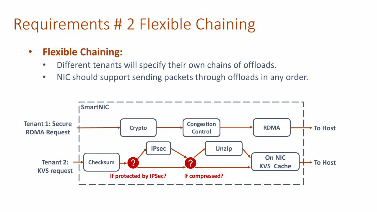
Requirements # 2 Flexible Chaining
• Flexible Chaining:• Different tenants will specify their own chains of offloads.
• NIC should support sending packets through offloads in any order.
IPsec
Tenant 2: KVS request
Checksum
Unzip
On NIC KVS Cache
To Host
If protected by IPSec? If compressed?
SmartNIC
Tenant 1: Secure RDMA Request
CryptoCongestion
ControlRDMA To Host

SmartNIC
Requirements # 3 Isolation# 4 Performance
• Isolation: • SmartNIC should provide
performance isolation between competing tenants.
• Performance:• SmartNIC should provide high
throughput for line-rate offloads.• SmartNIC should not incur
additional latency for low latency offload.
Tenant A’s traffic
Unzip
Shared OffloadPolicy: WFQ 2:1
Tenant B’s traffic

Motivation: Build a programmable NIC that meets all these requirements!

Outline
Motivation Existing NIC Limitation
Design& Evaluation

Existing NIC Design Overview
Pipeline of Offloads NIC
Manycore NIC
Chaining:
Generality:
Isolation:
Performance:
x Chaining:
Generality:
Isolation:
Performance:
xx x
x

Pipeline Design NIC
Chaining:
Generality:
Performance:
Isolation:
x
x
x

Pipeline Design NIC
Chaining:
Generality:
Performance:
Isolation:
x
x
x

Pipeline Design NIC
Chaining:
Generality:
Performance:
Isolation:
x
x
x

Pipeline Design NIC
Chaining:
Generality:
Performance:
Isolation:
x
x
x

Pipeline Design NIC
Chaining:
Generality:
Performance:
Isolation:
x
x
x

Pipeline Design NIC
Problems:• Chaining: static chaining.
Chaining:
Generality:
Performance:
Isolation:
x
x
x

Pipeline Design NIC
Problems:• Chaining: static chaining.• Generality: non-line rate offload will
cause Head-of-Line Blocking (HOL).• Isolation: poor Isolation when HOL
happens.
Chaining:
Generality:
Performance:
Isolation:
x
x
x

Pipeline Design NIC
Problems:• Chaining: static chaining.• Generality: non-line rate offload will
cause Head-of-Line Blocking (HOL).• Isolation: poor Isolation when HOL
happens.
Chaining:
Generality:
Performance:
Isolation:
x
x
x

Pipeline Design NIC
Problems:• Chaining: static chaining.• Generality: non-line rate offload will
cause Head-of-Line Blocking (HOL).• Isolation: poor Isolation when HOL
happens.
Chaining:
Generality:
Performance:
Isolation:
x
x
x

NIC
Manycore NIC
• Isolation: does not provide explicit supports for isolation.
• Performance: hard to saturate line-rate and high latency.
Chaining:
Generality:
Performance:
Isolation: xx
Problems:

The solution is --- PANIC!A new architecture for programmable NICs that supports full-line rate (> 100G) offload chaining
and multi-tenant traffic isolation

PANIC Design Overview
Packet Buffer
Compute Unit 1
(Service A)
Compute Unit 2
(Service B)
Compute Unit 3
(Service B)
Central SchedulerOn-chip
Memory
DMAEngine
DRAM Controller
port0
port1
port0 port1
Switching Fabric
RMTMAC PHY
MAC PHY
DDR 4PCIe Gen4 x8
QSFP28 QSFP28
port0 port1
PANIC Components:1. Reconfigurable-Match-
Action Pipeline: Parse packets and determine offload chain
2. Central Scheduler: enforce isolation policies and schedule packets
3. Independent Compute Unit: Support hardware accelerator or CPU core
4. High-throughput Switching Fabric: Interconnects different hardware resources.
Chaining:
Generality:
Isolation:
Performance:

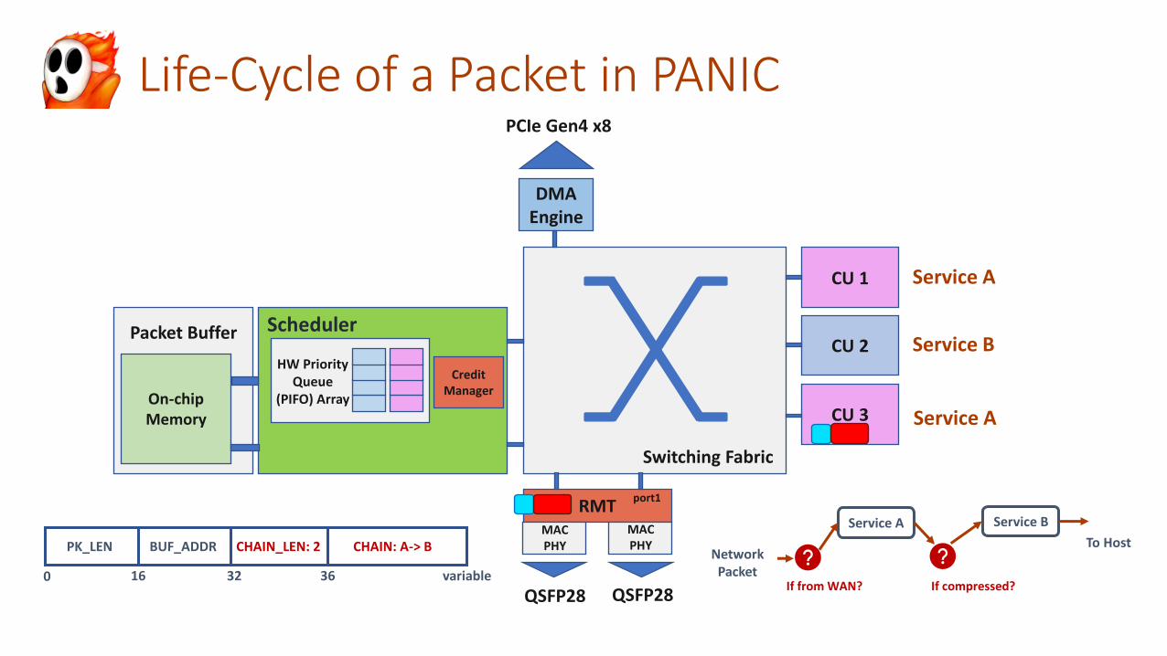
Life-Cycle of a Packet in PANIC
Packet Buffer
CU 1
CU 2
CU 3On-chip Memory
DMAEngine
Switching Fabric
RMTMAC PHY
MAC PHY
PCIe Gen4 x8
QSFP28 QSFP28
port0 port1
HW Priority Queue
(PIFO) Array
CreditManager
Service A
Service B
Service A
Service A
Network Packet
Service B
To Host
If from WAN? If compressed?
Scheduler
Life-Cycle of a Packet in PANIC
Packet Buffer
CU 1
CU 2
CU 3On-chip Memory
DMAEngine
Switching Fabric
RMTMAC PHY
MAC PHY
PCIe Gen4 x8
QSFP28 QSFP28
port0 port1
HW Priority Queue
(PIFO) Array
CreditManager
PK_LEN BUF_ADDR CHAIN: A-> B
0 16 32 36
CHAIN_LEN: 2
variable
Service A
Service B
Service A
Service A
Network Packet
Service B
To Host
If from WAN? If compressed?
Scheduler

RMT Pipeline
• Reconfigurable Match Action Table• Programmers can specify the set of fields in a packet to match on.
• Programmers compose the actions to modify packet fields.
• In PANIC, users program the match action tables:• The service chain for each tenant’s traffic.
• The isolation policy and priority number for each tenant’s traffic.
• Action stage, RMT generates a PANIC descriptor for every packet
Traffic ID Service Chain <Isolation Policy, Priority (Weight)>
1 A -> B <Weighted Fair Queuing, 3>
2 A -> C <Weighted Fair Queuing, 2>
… … …
PK_LEN BUF_ADDR CHAIN: A-> BCHAIN_LEN: 2 SCHE_METADATA: <WFQ, 3>

PANIC Scheduler:
Goal #1: Achieve high-performance chaining
Goal #2: Load-balance packets across parallel compute units in a service
Goal #3: Performance isolation across tenants
Goal #4: Buffer isolation across tenants

Problem:Chaining and Load Balancing
• Pull-based scheduling • Push-based scheduling
Scheduler
CU1
CU2
pull
pullService A
Service BEvery hop goes back to scheduler; cannot achieve high performance chaining!
Lead to load imbalance!
Achieve Load balancing! Low latency chaining!
Scheduler
CU1
CU2
CU3
Service A
Service B
Service B
push
push
Lead to packet dropping!
Goal #1: Achieve high-performance chaining
Goal #2: Load-balance packets across parallel compute units in a service.
Solution: Hybrid push-pull scheduling

PANIC Scheduler:Hybrid Push Pull Scheduling
• Hybrid Push Pull scheduling:• Compute units can either pull packet from the scheduler or accept the pushed packet from other
units.
• According to CUs’ load, switches between push pull scheduling.
• During Low Load: the packet is pushed to all the units in a chain.
• During High Load: the packet is sent back to the scheduler, until it can be pulled by an idle CU.
• Detour Routing : In push scheduling, if the downstream is busy due to a burst.
Scheduler
CU1
CU2
1. pull
2. push Scheduler
CU1
CU2
1. pull
2. push
BUSY!
3. detourScheduler
CU1
CU2
1. pull
3. pull
2. send back

PANIC Scheduler:Performance Isolation
Goal #3: Priority scheduling and performance isolation
Packet Buffer
PIFO Array
• PIFO array for performance Isolation:
• PIFO (PUSH IN, FIRST OUT Queue) runs like the hardware priority queue. One service has one logic PIFO queue.
• Packet descriptors is sorted according to the packet rank in per-service PIFO.
Service A
Tenant 1: 10Gbps Priority = 0 (Highest)
Tenant 2: 90Gbps Priority = 10 (Low)
Service B
Service C
ABC
Isolation Policy: Strict Priority
Scheduler
PK_LEN BUF_ADDR CHAIN: A-> BCHAIN_LEN: 2 SCHE_METADATA: <Strict, High>

PANIC Scheduler:Performance Isolation
Goal #3: Priority scheduling and performance isolation
Packet Buffer
PIFO Array
• PIFO array for performance Isolation:
• PIFO (PUSH IN, FIRST OUT Queue) runs like the hardware priority queue. One service has one logic PIFO queue.
• Packet descriptors is sorted according to the packet rank in per-service PIFO.
• Support different isolation policy • (WFQ, LSTF, Rate Limiting…)
Service A
Tenant 1: 10Gbps Priority = 0 (Highest)
Tenant 2: 90Gbps Priority = 10 (Low)
Service B
Service C
ABC
Isolation Policy: Strict Priority
Scheduler
PK_LEN BUF_ADDR CHAIN: A-> BCHAIN_LEN: 2 SCHE_METADATA: <Strict, High>

Problem:Buffer Isolation
Goal #4: Ensure buffer isolation across tenants
• Naïve Packet dropping method: drop the newest income packet when the buffer is full• No Isolation! A high-volume low-priority flow can lead to
packet loss for a high priority flow.

PANIC Scheduler: Prioritized Dropping
• Prioritized Dropping: drop the lowest rank packet when the buffer is almost full.• Extend PIFO’s interface to allow it to
support PUSH IN, FIRST OUT, REMOVE LAST• Isolation! PANIC can ensure the high
priority packet enters buffer and receive service.
Service A
Tenant 1: 10Gbps Priority = 0 (Highest)
Tenant 2: 90Gbps Priority = 10 (Low)
Service B
Service C
Isolation Policy: Strict Priority
Packet Buffer
PIFO Array
ABC
Scheduler

Compute Unit
• Compute Unit can either be a CPU core or a hardware accelerator, variable/non-line rate
• Traffic Manager handles communication with schedulero Offloads Engine can be designed without needing to understand other PANIC
components.
Offload Engine(Hardware
Accelerator/Core)
CacheScratchpad
Packet Buffer Traffic
Manager
Compute Unit
SwitchingFabric

Switching Fabric
• Providing offload chaining for an arbitrary chain.• The switching fabric is non-blocking and high-throughput
• Each interconnect port should send and receive at full line-rate (> 100Gbps)• A crossbar with a bit width of 512 bits at 250 MHz frequency.• Scalability? NoC topology is selected according to the CU number.

PANIC Implementation
• 100G FPGA prototype in ADM-PCIE-9V3 accelerator
• ~6K lines of Verilog code
• Prototype Components:o A lightweight RMT pipeline
o 8 * 8 full connected crossbar (512 bit width @ 250MHz)
o Dual-port central scheduler (512 bit width @ 250MHz)▪ PIFO block @ 125MHz
o Compute Units▪ AES-256-CTR encryption unit (24Gbps @ 250Mhz)
▪ SHA-3-512 hash unit (32Gbps @ 150Mhz)
▪ An RISC-V core unit (5-stage pipeline @ 250MHz)
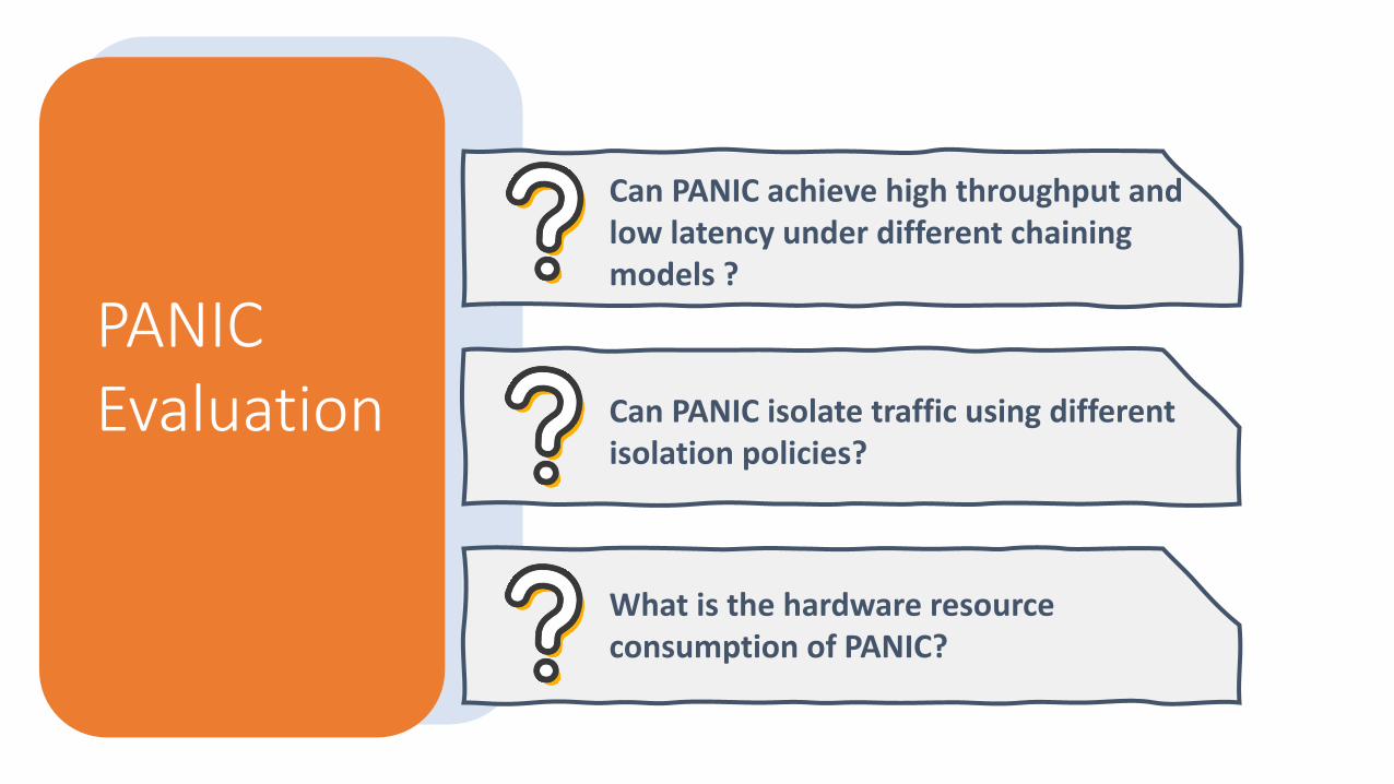
PANIC Evaluation
Can PANIC achieve high throughput and low latency under different chaining models ?
What is the hardware resource consumption of PANIC?
Can PANIC isolate traffic using differentisolation policies?

PANIC Evaluation
Can PANIC achieve high throughput and low latency under different chaining models ?
PANIC achieves 100G throughput and low latency chaining!
Chaining Model 1: Pipelined Chain
Setup: • Use delay unit emulate real compute unit.• Single line-rate delay unit for each service.• Each delay unit initially has 8 credits
A B C
100Gbps 100Gbps100Gbps
Input Output
PANIC
0
0.15
0.3
0.45
0.6
64 128 256 512 1024 1500
Late
ncy
(μ
s)
Packet Size (B)
0
20
40
60
80
100
64 128 256 512 1024 1500Thro
ugh
pu
t (G
bp
s)
Packet Size (B)

PANIC Evaluation
Can PANIC isolate traffic?
PANIC can isolate traffic using different isolation policy!
End-to-End experiment
Setup: • The sender server generate network traffic
using different traffic pattern. • 2 SHA engines and 2 AES engines are attached.• Isolation Policy: weighted fair queuing.
Traffic Group 1
SHA (S1,S2)
Traffic Group 2
AES (A1,A2)
32Gbps * 2
24Gbps * 2
Traffic Group 3
Weight = 1
Weight = 2
PANICBackground
0
20
40
60
80
100
1 3 5 7 9 11 13 15 17 19 21 23 25
Thro
ugh
pu
t (G
bp
s)
Time (s)
G1 G2 BG TOTAL
30GbpsG1G2BG
70Gbps
0Gbps
50Gbps50Gbps
0Gbps
30Gbps30Gbps40GbpsTr
affi
c P
atte
rn
Phase 1 Phase 2 Phase 3

Module Setting LUT (%) BRAM (%)
Crossbar 8 ports 5.5 0.00
Scheduler (PIFO)
PIFO size = 2565.18 (4.9)
0.07 (0.01)
Packet Buffer 256 KB 0.16 8.94
Simple RMT / 0.27 0.00
PANIC Evaluation
• Resource Usage in ADM-PCIE-9V3
• Most of the on-chip logic resources in PANIC is occupied by crossbar and PIFO.
• In total, PANIC only cost ~11% LUT resource and ~9% BRAM resource.
What is the hardware resource consumption of PANIC?
PANIC can easily fit on any middle-end FPGA without utilization or timing issues.

Conclusion
• PANIC is a full line-rate programmable NIC design that overcomes current NICs limitation in multi-tenant environments.