pap chilton 1877
TRANSCRIPT
Proceedings of the International Association for Shell and Spatial Structures (IASS) Symposium 2009, Valencia Evolution and Trends in Design, Analysis and Construction of Shell and Spatial Structures
28 September – 2 October 2009, Universidad Politecnica de Valencia, Spain Alberto DOMINGO and Carlos LAZARO (eds.)
Development of Timber Reciprocal Frame Structures in the UK
*John CHILTON
* Nottingham Trent University School of Architecture Design and Built Environment, Nottingham Trent University,
Burton Street, Nottingham, NG1 4BU, United Kingdom [email protected]
Abstract Although the structural principle of closed circuits of mutually supporting beams was known by Leonardo Da Vinci and has been used for hundreds, if not thousands of years (Popovic Larsen [8]), its rediscovery and renaming as the Reciprocal Frame, by the designer Graham Brown in 1987, has led to more structures of this type being built in the UK over the last 20 years. This paper briefly traces the development of reciprocal frames in the UK from Brown’s first simple gazebo structures, through its use in houses and commercial applications. It concludes with a description of the conception, design, analysis, manufacture and installation of a ten metre diameter reciprocal frame roof, completed in early 2009, which is composed of locally-sourced Douglas Fir roundwood trunks and constructed as part of the Woodland Community Hall at Hill Holt Wood, near Newark in the UK (Chilton et al [6]). This final project demonstrates an interesting juxtaposition of ‘low-tech’ materials (selected green de-barked timber) with ‘high-tech’ processing (CNC cutting and drilling of lap joints and fixing holes) and illustrates the collaborative processes necessary to ensure trouble-free erection of the ‘woven’ timber grid. Keywords: Reciprocal frame, timber structures
1. Introduction The author’s introduction to reciprocal frame structures came early in 1989 when approached by a designer, Graham Brown, who said that he had built some small garden pavilions with an innovative roof structure but was not exactly sure how the structure worked. As Brown had applied for a patent covering the structure’s design and use (Brown [2]) he wished to fully understand their behaviour. He also required contact with engineers who could calculate larger span structures in order to obtain requisite building permissions and assist him in defining the geometry of joints between the beams. These early gazebos, the first built in 1988, were of small diameter (approximately 4 m diameter) with a roof generally composed of seven solid timber beams placed on a heptagonal base.
1877
Proceedings of the International Association for Shell and Spatial Structures (IASS) Symposium 2009, Valencia Evolution and Trends in Design, Analysis and Construction of Shell and Spatial Structures
This enquiry prompted a curiosity in the author about the structure, which following a study at the University of Nottingham, on investigation, was discovered not to be new (Popovic [7]).
2. Houses (1990-) Following the construction of several small gazebo structures, interest in the reciprocal frame increased and requests for larger structures ensued. This manifested itself as a series of houses of increasing size, with timber roofs up to 13m diameter in plan. The first of these were built at the Findhorn Foundation (Chilton [3]).
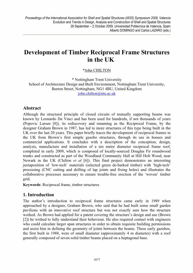
2.1. Whisky Barrel Houses, Findhorn Foundation, Scotland (1990) The first houses constructed by Graham Brown, known as the Whisky Barrel Houses, are located at the Findhorn Foundation, in Scotland, see Figure 1. Built in 1990, the walls of the houses are literally made from large wooden vats, approximately 6m diameter, used in the whisky-making process. On top of these sit seven-beam reciprocal roofs. The individual beams connect at notched joints around the centre of the roof to form a heptagonal rooflight. Of modular construction, insulated timber-framed panels sit between the beams connected to form a rigid conical shell.
Figure 1: External (left) and internal (right) views of one of the Whisky Barrel Houses at Findhorn Foundation, Scotland (1990). Photographs: John Chilton
2.2. House at Ferryhill, near Forres, Scotland (1993/4) The second house, constructed at Ferryhill, near Forres, and close to Findhorn, was of larger diameter and two storeys in height, introducing interesting architectural problems that were not fully resolved at that stage. In order to display the reciprocal frame to its full advantage there was a central hall and a wide balcony ran round most of the open upper floor. To some extent this limited the planning of the lower floor and, due to a planning constraint on the height of the building, resulted in restricted headroom around the perimeter of the upper floor.
1878
Proceedings of the International Association for Shell and Spatial Structures (IASS) Symposium 2009, Valencia Evolution and Trends in Design, Analysis and Construction of Shell and Spatial Structures
2.3. Continuing developments Muc was learnt from the the Ferryhill project and this was followed by a single-storey house at Saorsa, Ardlach, Nairn, Scotland (1995/6), which was at 13 m diameter the largest of the roofs built by Brown to date. In the same year three linked octagonal reciprocal frame roofed buildings were constructed for a small Permaculture Centre, in Bradford.
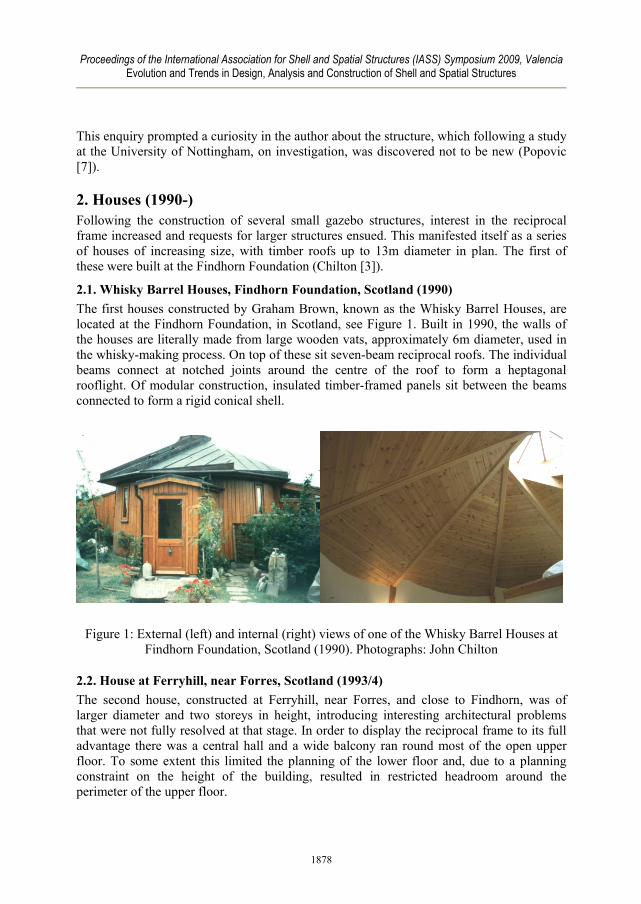
3. Colney Wood Memorial Park, Norwich (2003-) The most intense concentration of reciprocal frame buildings is at Colney Wood Memorial Park, near Norwich, which includes an office building, gathering hall, chapel and meditation pavilion/retreat. This woodland park is used for ecological burials and the group of reciprocal frame pavilions is seen to accord with the character and contemplative atmosphere of the park. The administration building (Figure 2) is different in that the reciprocal roof has beams of increasing length around the polygonal rooflight, to form a spiral in plan.
Figure 2: Administration Building at Colney Wood Memorial Park, Norwich (2003). Photograph: John Chilton
4. Woodland Community Hall, Hill Holt Wood, near Newark (2008/9) Recently a reciprocal frame roof of more complex and interesting configuration has been constructed at Hill Holt Wood, near Newark. This project was undertaken more than 20 years after Brown’s first gazebos. It was neither designed nor constructed by Brown and demonstrates several differences in design approach and manufacturing technique over those early and subsequent structures. Given its more sophisticated nature, this project will be discussed more fully here. It has also been described at length in (Chilton et al [6]). This structure covers the meeting room of the Woodland Community Hall at Hill Holt Wood, which is a social enterprise where disaffected young people are trained in woodland
1879
Proceedings of the International Association for Shell and Spatial Structures (IASS) Symposium 2009, Valencia Evolution and Trends in Design, Analysis and Construction of Shell and Spatial Structures
management. The Community Hall building was designed to allow them to participate in the construction process, wherever possible.
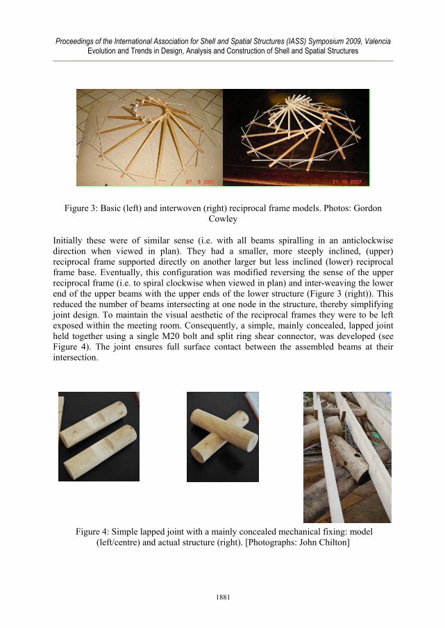
4.1. Design process Firstly the design evolved as the building was constructed rather than being defined right from start. The Woodland Community Hall was part of a UK Government financed Knowledge Transfer Partnership between Hill Holt Wood and the University of Lincoln, where the author was employed at the time. As part of that partnership, on a competitive basis, student groups from the university’s School of Architecture were asked to develop design ideas for the Community Hall for presentation to the clients, Hill Holt Wood. Although it was not initially part of their brief to include a reciprocal frame roof in the project, following a presentation and workshop conducted by the author, most groups chose to incorporate one. They were persuaded by the vibrant aesthetic which can be achieved, in particular when the structure is viewed from below. This was the case for the design selected by Hill Holt Wood, which was subsequently developed for Planning and Building Regulations approval by local architects Simons Design, Lincoln, in collaboration with the university and the client. Because of the nature of Hill Holt Wood’s business it had been decided early in the design process that simply de-barked roundwood (i.e. rough tree trunks) extracted by the client from the woods they manage would be used wherever possible. If these were to be used for the reciprocal frame roof some geometrical problems had to be resolved. As described in ( Ariza and Chilton [1], Chilton and Choo [4]; Chilton, Choo and Wilkinson [5]) several parameters in the design of reciprocal frame structures are completely interrelated. These are the number of beams in the configuration, their rise, the position of the point of support of each beam upon the next and, most importantly in this case, the shape and the cross-sectional dimensions of individual beams. Variation of these parameters precisely establishes the necessary spacing between beam centrelines at the point where they intersect. Clearly if de-barked tree trunks are to be used, the cross-section of the timber is not regular. This irregularity will vary from section to section and the trunk will also taper from base to top. Therefore, the available size of tree had consequences for both the number of beams in the configuration and the connection design. At this stage a single twelve-beam reciprocal frame structure of about 10 m diameter was proposed (Figure 3 (left)), much as in the earlier structures by Brown, but in this case it was used to support a large prismatic conical rooflight, thereby creating a dual-pitched roof. However, during design development meetings between the author, the client, the timber fabricator, Gordon Cowley, of Cowley Timberwork, Lincoln and his structural engineer John Westmuckett, of Edge Structures, London, this configuration evolved to include two reciprocal frames.
1880
Proceedings of the International Association for Shell and Spatial Structures (IASS) Symposium 2009, Valencia Evolution and Trends in Design, Analysis and Construction of Shell and Spatial Structures
Figure 3: Basic (left) and interwoven (right) reciprocal frame models. Photos: Gordon Cowley
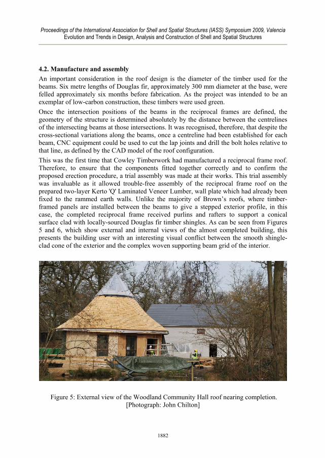
Initially these were of similar sense (i.e. with all beams spiralling in an anticlockwise direction when viewed in plan). They had a smaller, more steeply inclined, (upper) reciprocal frame supported directly on another larger but less inclined (lower) reciprocal frame base. Eventually, this configuration was modified reversing the sense of the upper reciprocal frame (i.e. to spiral clockwise when viewed in plan) and inter-weaving the lower end of the upper beams with the upper ends of the lower structure (Figure 3 (right)). This reduced the number of beams intersecting at one node in the structure, thereby simplifying joint design. To maintain the visual aesthetic of the reciprocal frames they were to be left exposed within the meeting room. Consequently, a simple, mainly concealed, lapped joint held together using a single M20 bolt and split ring shear connector, was developed (see Figure 4). The joint ensures full surface contact between the assembled beams at their intersection.
Figure 4: Simple lapped joint with a mainly concealed mechanical fixing: model
(left/centre) and actual structure (right). [Photographs: John Chilton]
1881
Proceedings of the International Association for Shell and Spatial Structures (IASS) Symposium 2009, Valencia Evolution and Trends in Design, Analysis and Construction of Shell and Spatial Structures
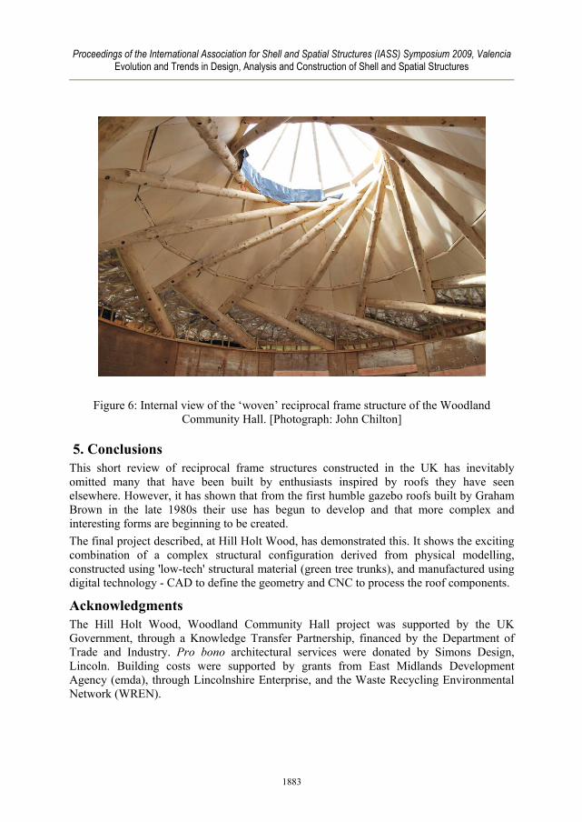
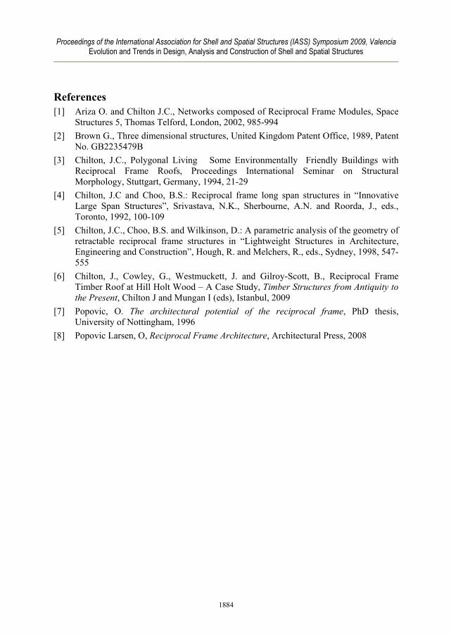
4.2. Manufacture and assembly An important consideration in the roof design is the diameter of the timber used for the beams. Six metre lengths of Douglas fir, approximately 300 mm diameter at the base, were felled approximately six months before fabrication. As the project was intended to be an exemplar of low-carbon construction, these timbers were used green. Once the intersection positions of the beams in the reciprocal frames are defined, the geometry of the structure is determined absolutely by the distance between the centrelines of the intersecting beams at those intersections. It was recognised, therefore, that despite the cross-sectional variations along the beams, once a centreline had been established for each beam, CNC equipment could be used to cut the lap joints and drill the bolt holes relative to that line, as defined by the CAD model of the roof configuration. This was the first time that Cowley Timberwork had manufactured a reciprocal frame roof. Therefore, to ensure that the components fitted together correctly and to confirm the proposed erection procedure, a trial assembly was made at their works. This trial assembly was invaluable as it allowed trouble-free assembly of the reciprocal frame roof on the prepared two-layer Kerto 'Q' Laminated Veneer Lumber, wall plate which had already been fixed to the rammed earth walls. Unlike the majority of Brown’s roofs, where timber-framed panels are installed between the beams to give a stepped exterior profile, in this case, the completed reciprocal frame received purlins and rafters to support a conical surface clad with locally-sourced Douglas fir timber shingles. As can be seen from Figures 5 and 6, which show external and internal views of the almost completed building, this presents the building user with an interesting visual conflict between the smooth shingle-clad cone of the exterior and the complex woven supporting beam grid of the interior.
Figure 5: External view of the Woodland Community Hall roof nearing completion. [Photograph: John Chilton]
1882
Proceedings of the International Association for Shell and Spatial Structures (IASS) Symposium 2009, Valencia Evolution and Trends in Design, Analysis and Construction of Shell and Spatial Structures
Figure 6: Internal view of the ‘woven’ reciprocal frame structure of the Woodland Community Hall. [Photograph: John Chilton]
5. Conclusions This short review of reciprocal frame structures constructed in the UK has inevitably omitted many that have been built by enthusiasts inspired by roofs they have seen elsewhere. However, it has shown that from the first humble gazebo roofs built by Graham Brown in the late 1980s their use has begun to develop and that more complex and interesting forms are beginning to be created. The final project described, at Hill Holt Wood, has demonstrated this. It shows the exciting combination of a complex structural configuration derived from physical modelling, constructed using 'low-tech' structural material (green tree trunks), and manufactured using digital technology - CAD to define the geometry and CNC to process the roof components.
Acknowledgments The Hill Holt Wood, Woodland Community Hall project was supported by the UK Government, through a Knowledge Transfer Partnership, financed by the Department of Trade and Industry. Pro bono architectural services were donated by Simons Design, Lincoln. Building costs were supported by grants from East Midlands Development Agency (emda), through Lincolnshire Enterprise, and the Waste Recycling Environmental Network (WREN).
1883
Proceedings of the International Association for Shell and Spatial Structures (IASS) Symposium 2009, Valencia Evolution and Trends in Design, Analysis and Construction of Shell and Spatial Structures
References [1] Ariza O. and Chilton J.C., Networks composed of Reciprocal Frame Modules, Space
Structures 5, Thomas Telford, London, 2002, 985-994 [2] Brown G., Three dimensional structures, United Kingdom Patent Office, 1989, Patent
No. GB2235479B [3] Chilton, J.C., Polygonal Living Some Environmentally Friendly Buildings with
Reciprocal Frame Roofs, Proceedings International Seminar on Structural Morphology, Stuttgart, Germany, 1994, 21-29
[4] Chilton, J.C and Choo, B.S.: Reciprocal frame long span structures in “Innovative Large Span Structures”, Srivastava, N.K., Sherbourne, A.N. and Roorda, J., eds., Toronto, 1992, 100-109
[5] Chilton, J.C., Choo, B.S. and Wilkinson, D.: A parametric analysis of the geometry of retractable reciprocal frame structures in “Lightweight Structures in Architecture, Engineering and Construction”, Hough, R. and Melchers, R., eds., Sydney, 1998, 547-555
[6] Chilton, J., Cowley, G., Westmuckett, J. and Gilroy-Scott, B., Reciprocal Frame Timber Roof at Hill Holt Wood – A Case Study, Timber Structures from Antiquity to the Present, Chilton J and Mungan I (eds), Istanbul, 2009
[7] Popovic, O. The architectural potential of the reciprocal frame, PhD thesis, University of Nottingham, 1996
[8] Popovic Larsen, O, Reciprocal Frame Architecture, Architectural Press, 2008
1884