paper-based microfluidic fuel · pdf filepaper-based microfluidic fuel cells ... on cop), a...
TRANSCRIPT

PAPER-BASED MICROFLUIDIC FUEL CELLS J.P. Esquivel1,2*, F. J. del Campo1, J.L. Gómez de la Fuente3, S. Rojas3 and N. Sabaté1
1Instituto de Microelectrónica de Barcelona, IMB-CNM (CSIC), SPAIN, 2University of Washington, USA, 3Instituto de Catálisis y Petroleoquímica, ICP (CSIC), SPAIN
ABSTRACT
This work presents a paper-based membraneless microfluidic fuel cell. The device benefits from the laminar flow occurring in a porous material by capillarity to separately react with two parallel streams, anolyte and catholyte, without a separating membrane. Unlike conventional microfluidic fuel cells, the present device does not require external pumps or any other ancillary devices to operate, as reactants flow by capillary forces alone. This work represents the starting point in the development of a power source for capillary-based autonomous sensing systems capable of harvesting the energy needed for the measurement from the biological sample to be analyzed. KEYWORDS: Fuel cell, paper microfluidics, autonomous point-of-care
INTRODUCTION
Paper-like materials have been used in medical diagnostics for decades, and the last few years have seen a revival of the classical lateral flow strips towards the highly promising field of paper microfluidics, with new applications blooming fast.[1] This recent interest in paper as thin, flexible and disposable material has led to the development of paper-based power sources such as batteries,[2] capacitors [3] or solar cells.[4]
This paper presents the first paper-based membraneless microfluidic fuel cell. Anolyte and catholyte streams flow in
parallel and react separately through the porous matrix and, thanks to capillarity, this device avoids the usual separating membrane present in other fuel cells.[5] Also unlike conventional microfluidic fuel cells, the present device does not require external pumps or any other ancillary devices to operate, as reactants flow by capillary forces alone.
The device was fabricated using a combination of paper and polymeric laminate materials, and the catalyst layers
were sprayed over evaporated gold electrodes patterned by standard photolithographic methods.
EXPERIMENTAL RESULTS AND DISCUSSION Before assembling the fuel cell, electrode and channel geometries were optimized by electrochemical techniques
using ferrocyanide solutions in the setup shown in Figure 1a. The measurement setup consisted of a micromachined acrylic piece that held a glass slide, electrical connections and a lid for an absorber, all fixed by magnets. The glass slide was used as a substrate to support the electrodes (Au-evaporated on COP), a Y-shaped paper strip (Fusion 5, Whatman) and the absorber (Kimwipe). 0.5M KNO3 (channel A) and 2mM K4Fe(CN)6 in 0.5M KNO3 (channel B) solutions were supplied into each of the inlets of the paper strip. As the solutions flowed parallel along the strip, the electrical response of each stream was measured by the electrodes. Figure 1b displays chronoamperometric data showing the lack of cross diffusion of reagents between the two parallel streams running along the paper strip.
a)
b)
Figure 1: (a) Picture of the setup for electrochemical characterization. (b) Chronoamperometry of the device using
2mM K4Fe(CN)6 in 0.5M KNO3 in one side (stream A) and 0.5M KNO3-only in the other (stream B).
After this, the device was configured as a direct methanol microfluidic fuel cell. In this case, the paper strip was laminated between layers of pressure sensitive adhesives, as shown in Figure 2. The electrodes consisted of 5mm-long pieces of COP metallized by a thin layer of Au on which catalyst layers were deposited by spray coating with a metal
978-0-9798064-6-9/µTAS 2013/$20©13CBMS-0001 1251 17th International Conference on MiniaturizedSystems for Chemistry and Life Sciences27-31 October 2013, Freiburg, Germany
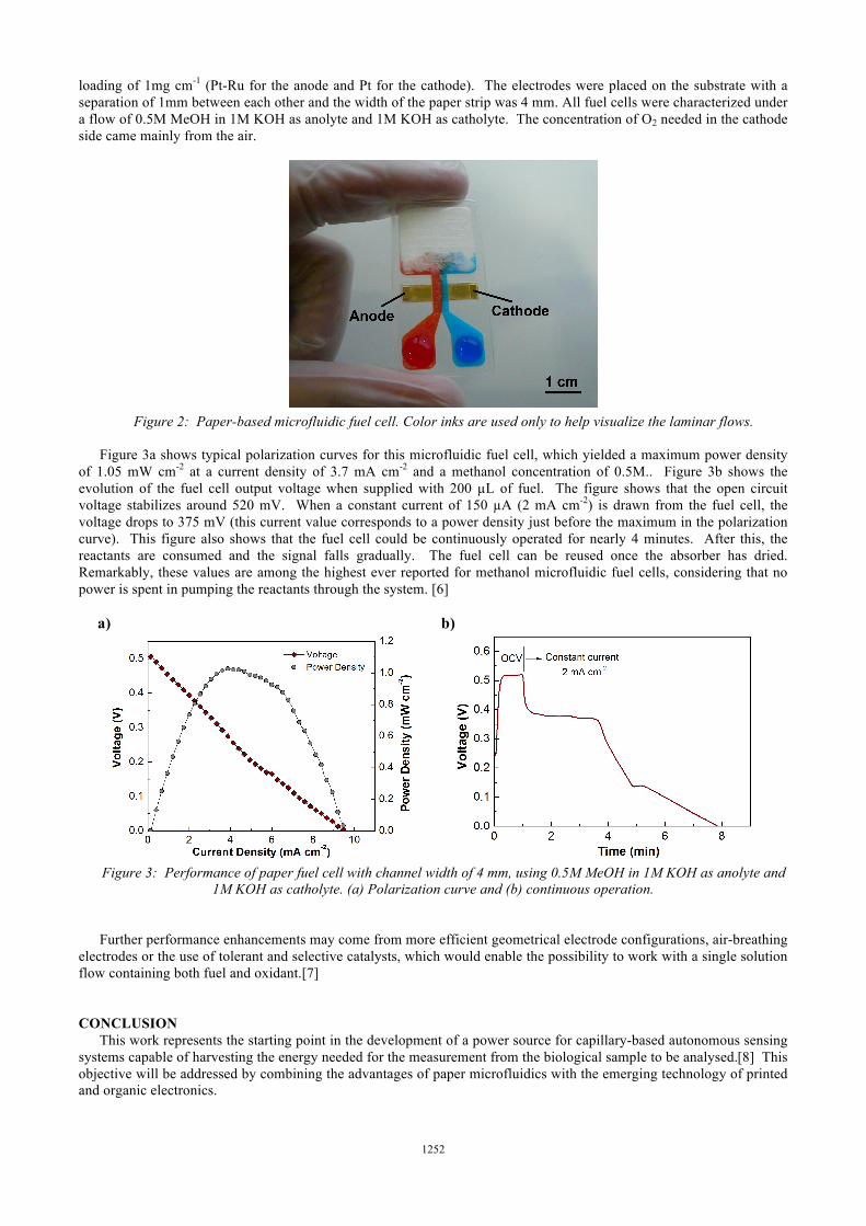
loading of 1mg cm-1 (Pt-Ru for the anode and Pt for the cathode). The electrodes were placed on the substrate with a separation of 1mm between each other and the width of the paper strip was 4 mm. All fuel cells were characterized under a flow of 0.5M MeOH in 1M KOH as anolyte and 1M KOH as catholyte. The concentration of O2 needed in the cathode side came mainly from the air.
Figure 2: Paper-based microfluidic fuel cell. Color inks are used only to help visualize the laminar flows.
Figure 3a shows typical polarization curves for this microfluidic fuel cell, which yielded a maximum power density
of 1.05 mW cm-2 at a current density of 3.7 mA cm-2 and a methanol concentration of 0.5M.. Figure 3b shows the evolution of the fuel cell output voltage when supplied with 200 µL of fuel. The figure shows that the open circuit voltage stabilizes around 520 mV. When a constant current of 150 µA (2 mA cm-2) is drawn from the fuel cell, the voltage drops to 375 mV (this current value corresponds to a power density just before the maximum in the polarization curve). This figure also shows that the fuel cell could be continuously operated for nearly 4 minutes. After this, the reactants are consumed and the signal falls gradually. The fuel cell can be reused once the absorber has dried. Remarkably, these values are among the highest ever reported for methanol microfluidic fuel cells, considering that no power is spent in pumping the reactants through the system. [6]
a)
b)
Figure 3: Performance of paper fuel cell with channel width of 4 mm, using 0.5M MeOH in 1M KOH as anolyte and
1M KOH as catholyte. (a) Polarization curve and (b) continuous operation. Further performance enhancements may come from more efficient geometrical electrode configurations, air-breathing
electrodes or the use of tolerant and selective catalysts, which would enable the possibility to work with a single solution flow containing both fuel and oxidant.[7]
CONCLUSION This work represents the starting point in the development of a power source for capillary-based autonomous sensing
systems capable of harvesting the energy needed for the measurement from the biological sample to be analysed.[8] This objective will be addressed by combining the advantages of paper microfluidics with the emerging technology of printed and organic electronics.
1252

ACKNOWLEDGEMENTS
GE Healthcare and Adhesives Research are acknowledged for their support with materials used in this work. This research was supported by a Marie Curie International Outgoing Fellowship within the 7th European Community Framework Programme. N. S. would like to thank the financial support received from her postdoctoral program Ramón y Cajal. REFERENCES [1] Ballerini D., Li X. and Shen W. Patterned paper and alternative materials as substrates for low-cost microfluidic
diagnostics Microfluidics and Nanofluidics 13 (2012) 769-87 [2] Thom N.K., Yeung K., Pillion M.B. and Phillips S.T. "Fluidic batteries" as low-cost sources of power in paper-
based microfluidic devices Lab on a Chip 12 (2012) 1768-70 [3] Nyholm L., Nyström G., Mihranyan A. and Strømme M. Toward Flexible Polymer and Paper-Based Energy
Storage Devices Advanced Materials 23 (2011) 3751-69 [4] Barr M.C., Rowehl J.A., Lunt R.R., Xu J., Wang A., Boyce C.M., Im S.G., Bulović V. and Gleason K.K. Direct
Monolithic Integration of Organic Photovoltaic Circuits on Unmodified Paper Advanced Materials 23 (2011) 3500-5
[5] Osborn J.L., Lutz B., Fu E., Kauffman P., Stevens D.Y. and Yager P. Microfluidics without pumps: reinventing the T-sensor and H-filter in paper networks Lab on a Chip 10 (2010) 2659-65
[6] Kjeang E., Djilali N. and Sinton D. Microfluidic fuel cells: A review Journal of Power Sources 186 (2009) 353-69 [7] Mousavi Shaegh S.A., Nguyen N.-T. and Chan S.H. A review on membraneless laminar flow-based fuel cells
International Journal of Hydrogen Energy 36 (2011) 5675-94 [8] Esquivel J.P., Colomer-Farrarons J., Castellarnau M., Salleras M., Del Campo F.J., Samitier J., Miribel-Catala P.
and Sabate N. Fuel cell-powered microfluidic platform for lab-on-a-chip applications: Integration into an autonomous amperometric sensing device Lab on a Chip 12 (2012) 4232-5
CONTACT *J.P. Esquivel; [email protected]
1253