paper magnetic field homogeneity of birdcage …takahashi/pdf/a112.pdfieice trans. commun.,...
TRANSCRIPT

IEICE TRANS. COMMUN., VOL.E97–B, NO.4 APRIL 2014791
PAPER
Magnetic Field Homogeneity of Birdcage Coil for 4 T MRI Systemwith No Lumped Circuit Elements
Ryotaro SUGA†a), Student Member, Kazuyuki SAITO††b), Member, Masaharu TAKAHASHI††, Senior Member,and Koichi ITO††, Fellow
SUMMARY In recent years, magnetic resonance imaging (MRI) sys-tems that operate up to under 3 T are being used in clinical practice in Japan.In order to achieve the requirements of higher image quality and shorterimaging times, devices that utilize high magnetic fields (> 3 T) and highpower electromagnetic (EM) wave pulses have been developed. The rise ofthe static magnetic field is proportional to the increase of the EM wave fre-quency which raises the issue of variation in capacitance used in the radiofrequency (RF) coil for MRI system. In addition, increasing power causesproblems of withstanding voltage and these approaches leads to generationof non-uniform magnetic field inside the RF coil. Therefore, we proposeda birdcage coil without the use of lumped circuit elements for MRI sys-tems in previous study. However, it is difficult to fabricate this birdcagecoil. Hence, simply-structured birdcage coil with no lumped circuit ele-ments is desired. In this paper, we propose a simply-structured birdcagecoil with no lumped circuit elements for a 4 T MRI system. In addition,the authors investigated the input impedance and magnetic field distribu-tion of the proposed coil by FDTD calculations and measurements. Theresults confirm that the proposed birdcage coil matches the performance ofthe conventional birdcage coil which includes several capacitors.key words: magnetic resonance imaging (MRI), birdcage coil, finite-difference time-domain (FDTD) method, biological tissue-equivalent phan-tom
1. Introduction
Magnetic resonance imaging (MRI) is being widely usedto obtain clear images inside the human body, especiallyof high water content tissues. The fundamental princi-ple of MR imaging is to receive nuclear magnetic reso-nance (NMR) signals induced by irradiating the human bodyplaced inside a strong static magnetic field with electromag-netic (EM) wave pulses. The MRI system is composedof various elements including a radio frequency (RF) coil,which plays an essential role in imaging [1]. Several typesof RF coils, such as birdcage coils, saddle coils, surfacecoils, transverse electromagnetic (TEM) coils etc. have beendeveloped and used depending on the body part to be im-aged [1]–[4]. These RF coils operate as an antenna that “ir-radiates the body with EM wave pulses in order to generateNMR signals” and “receiving the NMR signals emitted fromthe body”. This paper focuses on the birdcage coil, which is
Manuscript received August 1, 2013.Manuscript revised November 26, 2013.†The author is with the Graduate School of Engineering, Chiba
University, Chiba-shi, 263-8522 Japan.††The authors are with the Center for Frontier Medical Engi-
neering, Chiba University, Chiba-shi, 263-8522 Japan.a) E-mail: [email protected]) E-mail: kazuyuki [email protected]
DOI: 10.1587/transcom.E97.B.791
the most popular type of volume coil. Frequency to emit theNMR signal depends on nucleus properties in human body.It is necessary to use an EM wave in certain specified fre-quency to emit the NMR signal. Here, frequency of EMfields, f [Hz] is given by the following equation.
f = γ · B (1)
where f is the Lamor precession or resonant frequency ofthe nucleus [Hz], γ is the gyromagnetic ratio of nuclear[Hz/T]. In the case of water composed of hydrogen atoms,γ = 42.6 MHz/T. Additionally, B is the magnitude of thestatic magnetic flux density [T]. In this paper, the authors de-scribe magnetic flux density as magnetic field for reasons ofexpediency. Thus, frequency to emit NMR signal is directlyproportional to the strength of the static magnetic field.
Recent MRI systems that operate at up to 3 T are beingused in clinical practice in Japan [5]. In order to achievethe requirement of obtaining more high-quality images andshort imaging time, devices, which utilize high magneticfield (> 3 T) and high power EM wave pulses, have beendeveloped [6], [7]. However, some problems caused by highmagnetic field and high power EM wave pulses. For in-stance, the increase of static magnetic field strength causesa rise in the frequency of EM pulses. In such a case, smallvariability of capacitances used in the birdcage coil, whichis one of the most-used volume coils and is loaded a lotof uniform capacitances, will not be ignored. In addition,the use of high power EM pulses will induce breakdown ofthe capacitances. The improvement of the above problemswould increase costs for manufacturing of the coil. It is pre-dicted that these problems are going to become increasinglyserious problems when high magnetic field (> 3 T) is uti-lized with devices for the MRI system. Hence, if we candevelop the birdcage coil for MRI system with no lumpedcircuit elements such as capacitance, it is extremely useful.For this reason, we have developed birdcage coil for MRIsystem with no lumped circuit element [8]. This birdcagecoil has circular conductors which are two different diame-ters. These conductors were constructed on both surfaces ofdielectric cylinder. In this way, this birdcage coil can gener-ate capacitance between circular conductors which are twodifferent diameters. Due to this, birdcage coil does not needany capacitors as lumped circuit elements. However, if con-ductors on dielectric cylinder are out of position during pro-cess of manufacture, characteristics of this birdcage coil be-come depleted because capacitance changes between some
Copyright c© 2014 The Institute of Electronics, Information and Communication Engineers

792IEICE TRANS. COMMUN., VOL.E97–B, NO.4 APRIL 2014
conductors on both surfaces of dielectric cylinder. In otherwords, it is difficult to fabricate this birdcage coil. There-fore, simply-structured birdcage coil with no lumped circuitelements to reduce manufacturing error is desired.
In this paper, we proposed the simply-structured bird-cage coil with no lumped circuit elements to reduce manu-facturing error. To be more specific, conductors of the bird-cage coil with no lumped circuit elements were constructedon single side surface of dielectric cylinder. It is consideredthat proposed birdcage coil can be manufactured by tech-nique of making a single side printed circuit board.
2. Calculation Model
2.1 Head Model
Figure 1 show the head model used in the numerical calcu-lation and the experiment. This model is 180 mm in diame-ter, 250 mm in length and is made of a uniform medium ofan average brain tissue [9]. The composition of the phan-tom for experiment is listed in Table 1. The target valuesof electrical properties of the phantom are εr = 58.2 andσ = 0.49 S/m at 170 MHz [10]. At 170 MHz, the errors be-tween the target values and the measured electrical constantsare 3.4% and 4.1% for relative permittivity εr and conduc-tivity σ, respectively. Thus, there is no influence on the bird-cage coil performances with such differences.
2.2 Structure of the Birdcage Coil
The RF coil employed in this paper is a birdcage coil for 4 TMRI system. From the Eq. (1), operating frequency of thecoil is approximately 170 MHz. Figure 2(a) shows structureof the proposed birdcage coil, previous birdcage coil withno lumped circuit element in Ref. [8] is shown Fig. 2(b) and
Fig. 1 Head model.
Table 1 Composition of phantom.
the conventional birdcage coil is shown Fig. 2(c) for com-parison, respectively. Figure 3 shows sectional view of twobirdcage coils. The birdcage coil consists of two circularconductors and some conductors which make a connectionwith circular conductors. The former is called end-ring andthe latter is called element. Here, both coils consist of six-teen elements.
Moreover, in order to generate a homogenous magneticfield inside the birdcage coil and control the resonance fre-quency of the conventional birdcage coil to approximately170 MHz, a total of thirty two capacitors were attached tothe both end-rings of the conventional birdcage coil such asFig. 2(c). Resonance frequency of the birdcage coil is variedaccording to the capacitance. In addition, magnetic field dis-tribution inside the coil is varied according to current patternon elements. For example, to create a homogeneous mag-netic field inside cylindrical birdcage coils, the current pat-tern on a conducting surface should have a sinusoidal depen-dence on the azimuthal angle of the element location. Pleasesee Ref. [1] for more information about operating principleof the birdcage coil. In this paper, all capacitors have 14.4pFbased on an analysis of Birdcage Builder [11] which is com-puter program provided by Pennsylvania State University.The Birdcage Builder can be used to calculate the currentpattern on a conducting surface of element location, and thenecessary capacitances of the birdcage coil of a given ge-ometry (diameter of birdcage coil, number of elements, re-quired resonant frequency, and so on) by performing lumpedcircuit analysis using virtual ground assumptions. In capac-itance calculation, each end-ring was treated as a numberof segments located between the elements, and the requiredcapacitances were calculated as follows: (1) calculate thecurrent intensity in the leg following the desired current dis-tribution (for example, it will be a sinusoidal distribution ina circular coil design) according to elements angular posi-tion, (2) calculate current intensity in the end-ring segments
Fig. 2 Birdcage coil.

SUGA et al.: MAGNETIC FIELD HOMOGENEITY OF BIRDCAGE COIL FOR 4 T MRI SYSTEM WITH NO LUMPED CIRCUIT ELEMENTS793
Fig. 3 Sectional view of birdcage coils.
Fig. 4 Circuit model in the birdcage coil for capacitance calculation.
by Kirchhoff’s law, (3) calculate the effective inductance oflegs concerning the effect of RF shield, (4) calculate the ef-fective inductance of end-ring segments, and (5) calculatethe capacitance by performing lumped circuit analysis usingKirchhoff’s law. For example, a circuit model for birdcagecoil design is shown in Fig. 4. The Leff and Leff
ER are the ef-fective inductance of the element and end-ring segment, Cis the capacitor inserted on the end-ring segment, I is thecurrent intensity in the end-ring segment, and n is the index.
Figure 2(a) is the proposed birdcage coil without theuse of lumped circuit elements. In order to control the res-onance frequency of the proposed birdcage coil, gaps areused instead some capacitors such as Fig. 2(a). Therefore,this birdcage coil does not need the capacitor that is thelumped circuit elements. Structure of the proposed birdcagecoil is simpler than the coil in Ref. [8] because conductor ofRef. [8] was constructed on both surfaces of dielectric cylin-der. Here, end-rings and sixteen elements were constructedon the dielectric pipe (εr = 2.1), whose pipe wall thicknessis 3 mm.
In this paper, two coils and RF shield are same in sizesuch as Fig. 3(a) and (b). The diameter and the length ofboth coils are 300 mm and 330 mm each, which is suffi-ciently large for the head model to be set inside. Addition-ally, both coils are enclosed in a cylindrical RF shield. Thediameter and the length of the RF shield are 400 mm and440 mm, respectively. All these are composed of metallicsheets. Dimensions of coil and the cylindrical RF shieldwere determined by Refs. [9], [12], and [13]. In addition,two feeding points were employed in these calculations andthe phase difference between them is 90 degree. This exci-tation method is called “quadrature excitation” and can gen-erate uniform rotate magnetic field inside the birdcage coil.
Fig. 5 The numerical calculation model consisting of the birdcage coiland the head model (Coordinate origin is center of the coil).
Table 2 The parameters used in FDTD calculations.
2.3 Numerical Calculation Model and Conditionsa
In the numerical calculation, the input impedance |Z| at thefeeding point of the birdcage coil was calculated by theFDTD method [14], and the magnetic field inside the coilwas calculated for comparison with the measurements. Theparameters used in FDTD calculations are listed in Table 2.
Figure 5(a) shows the numerical calculation model ofthe birdcage coil and the head model. The head model isplaced in the center of the coil. Figure 5(b) shows enlargedview of around the feeding point of proposed birdcage coil.Feeding points are modeled such as a Fig. 5(b). For the cal-culation of the input impedance, a derivative Gaussian pulsewas excited with 50-Ω internal resistance at the feeding gapat the position φ = 0◦. In contrast, a continuous sinusoidalwave was inputted at the feeding gaps at the positions φ = 0◦and φ = 90◦ to calculate magnetic field distribution. Inorder to reduce computational resources, the non-uniform

794IEICE TRANS. COMMUN., VOL.E97–B, NO.4 APRIL 2014
grid FDTD algorithm was adopted. The absorbing bound-ary condition is 8 layers of Perfectly Matched Layer (PML).
3. Input Impedance of the Proposed Coil
In this paper, in order to adjust the resonant frequency,widths of gaps between end-rings g (see Fig. 2(a)) arechanged. Other parameters (e.g. overlap-length betweenthree end-rings, distance between element and center end-ring, and so on) are maintained constant. Figure 6 showrelationships between resonant frequency and g. In this pa-per, impedance-matching of the birdcage coil is not con-sidered because MRI system usually has matching circuit(i.e. we consider only adjust the resonant frequency of thecoil.). Moreover, birdcage coil is considered as a paral-lel resonant circuit as shown in Fig. 4. Generally, a par-allel resonant circuit has high impedance at resonant fre-quency. In other words, absolute value of impedance haslocal maximum value at resonant frequency. Therefore, ab-solute value of impedance is shown in this paper because itis only necessary to adjust the resonant frequency. As a re-sult, the resonance frequency was confirmed to be approx-imately 170 MHz, when widths of gaps are 0.2 mm. Thus,it is considered that proposed coil when widths of gaps are0.2 mm and conventional coil which are loaded with capac-itance of 14.4 pF are equivalent.
In order to compare the measured and calculated in-put impedances of the proposed birdcage coil containing thehead model, when widths of gaps are 0.2 mm are shown inFig. 7. The continuous line is the calculated result and thebroken line is the measured result. The input impedance wascalculated at the feeding point at φ = 0◦, same as the mea-sured. Here, the measuring instrument was N5230C PNA-Lnetwork analyzer by the Agilent Technologies, Santa Clara,California.
As a result, the resonance frequency is confirmed tobe approximately 170 MHz. However, slight shifts in res-onant frequency and absolute value of impedance betweenthe measured and calculated results were confirmed. Theseshifts attributed to fabrication error in, such as, the dimen-sion of gaps.
4. Magnetic Field Distribution
It is considered that magnetic field homogeneity in the cen-ter of the coil is important because the coil is placed in sucha way that target organ is positioned roughly in the centerof the coil. In addition, the direction of rotation of the nu-clear is radial direction of the coil (i.e. x-y plane). Thus, it isnecessary to generate rotate magnetic field in x-y plane. Forthese reasons, this paper describes the results of magneticfield distributions in x-y plane.
4.1 Calculated Magnetic Field Distribution
Figure 8(a) shows the magnetic field distribution of theproposed coil containing the head model in the x-y plane
Fig. 6 Input impedance.
Fig. 7 The measured and calculated input impedance of the proposedcoil.
at center of the coil (z = 0 mm). In addition, the mag-netic field distribution of the conventional coil containingthe head model is shown in Fig. 8(b) for comparison. Here,the magnetic field levels of proposed coil and conventionalcoil were normalized with equal input power. From theseresults, it was confirmed that both coils generate uniformmagnetic field inside the head model. Figure 9 shows theprofiles of magnetic field. The observation line is x axis aty = 0 mm in Fig. 8. The continuous line is the result ofproposed coil and the broken line is the result of conven-tional coil. As a result, it was confirmed that the proposedcoil has an equivalent uniformity to the conventional bird-cage coil. In addition, each component (Hx, Hy and Hz) ofmagnetic field distributions inside the proposed coil contain-ing the head model is shown in Fig. 10. From these results,we confirmed that level of Hz component, which is parallelto the axial direction of the coil, was small in comparisonwith the levels of Hx and Hy components. Thus, the spa-tial phase difference of 90 degrees caused by quadrature ex-citation between Hx and Hy components of magnetic fielddistributions were observed. These distributions were ob-served for a similar result in conventional birdcage coil andit is non-unique characteristics of proposed coil. From theseresults, it is suggested that the proposed birdcage coil can

SUGA et al.: MAGNETIC FIELD HOMOGENEITY OF BIRDCAGE COIL FOR 4 T MRI SYSTEM WITH NO LUMPED CIRCUIT ELEMENTS795
Fig. 8 Magnetic field distribution (absolute value).
Fig. 9 Profiles of magnetic field (absolute value).
use for MR imaging. Additionally, in order to compare themagnetic field uniformity inside the head, average variationof the magnetic field inside a head model were calculatedby applying the following Eq. (1). The average variation isdefined as
δave =1
SHave
�S|H − Have| ds (2)
where S denotes the circular region [m2], and Have denotesaverage value of H over the region. In this case, S is crosssection of the phantom. In addition, range of Have as de-fined from 0 to 1. Table 3 illustrates the average variationsof magnetic field in the head model for the proposed coil andthe conventional coil. The average variation of the proposedcoil is approximately δave = 0.147, the average variation ofthe conventional coil is the δave = 0.158. As a result, aver-age variation of the conventional coil is slightly larger thanthe average variation of the proposed coil. However, errorof the average variation between the conventional coil andproposed coil was negligible small in terms of practice. Ac-cordingly, it is considered that the proposed birdcage coilhas an equivalent homogeneity of magnetic field to the con-ventional birdcage coil.
Fig. 10 Magnetic field distribution.
Table 3 Comparison of the average variation δave.
Fig. 11 Setup for measurement of magnetic field distribution.
4.2 Measurement of the Magnetic Field Distribution
Here, we describe the measurement of the magnetic fielddistribution inside the human head model and thereby val-idate the calculated results. Figure 11 shows the experi-mental setup, where the arrangement of the birdcage coiland human head model is the same as that in Fig. 5. Here,gel phantom is used as a human head model. Gel phan-tom is filled in dielectric pipe (εr = 2.1) and thickness ofdielectric pipe is 3 mm. The composition of the gel phan-tom for measurement of magnetic field distribution is listed
796IEICE TRANS. COMMUN., VOL.E97–B, NO.4 APRIL 2014
Table 4 Composition of gel phantom.
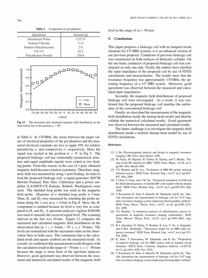
Fig. 12 The measured and calculated magnetic field distribution on theobservation line at the position ϕ = 90◦.
in Table 4. At 170 MHz, the errors between the target val-ues of electrical properties of the gel phantom and the mea-sured electrical constants are less or equal 10% for relativepermittivity εr and conductivity σ, respectively. Here, thesignal was excited at the position φ = 0◦ in Fig. 5. Theproposed birdcage coil has rotationally-symmetrical struc-ture and equal amplitude signals were exited at two feed-ing points. From this reason, in the case of 1-port, obtainedmagnetic field becomes rotation symmetry. Therefore, mag-netic field was measured by using 1-port feeding. In order tofeed the proposed birdcage coil, a signal generator (8657BHewlett Packard, Palo Alto, California) and a power am-plifier (LA100UF-CE Kalmus, Bothell, Washington) wereused. The shielded loop probe was used as the magneticfield probe. Diameter of a shielded loop probe is 5 mm.Then, Hx and Hy were measured by orienting the probe an-tenna along the x axis at y = 0 mm in Fig. 8. Here, the Hz
component is omitted because its level is very low as com-pared to Hx and Hy. A spectrum analyzer (Agilent E4403B)was used to measure the received signal level. The scanninginterval on the line was 10 mm. Figure 12 compares themeasured and calculated magnetic field distribution on theobservation line (y = z = 0 mm, −70 ≤ x ≤ 70 mm). Thelevels are normalized with the maximum value on the obser-vation lines in both cases. The continuous line is the calcu-lated result and square symbols are the measured result. Asa result, we confirmed that measurement result disagree withthe calculation result in the range of −70 mm ≤ x ≤ −50 mmbecause the range is noise floor of the spectrum analyzer.However, good agreement was observed between the mea-sured and numerical calculated results of the magnetic field
level in the range of |x| < 50 mm.
5. Conclusions
This paper proposes a birdcage coil with no lumped circuitelements for 4 T MRI systems; it is an enhanced version ofour previous proposal. Conductor of previous birdcage coilwas constructed on both surfaces of dielectric cylinder. Onthe one hand, conductor of proposed birdcage coil was con-structed on only one side. Firstly, the authors have clarifiedthe input impedance of the proposed coil by use of FDTDcalculations and measurements. The results show that theresonance frequency was approximately 170 MHz, the op-erating frequency of a 4 T MRI system. Moreover, goodagreement was observed between the measured and calcu-lated input impedances.
Secondly, the magnetic field distributions of proposedbirdcage coil were investigated. As a result, it was con-firmed that the proposed birdcage coil matches the unifor-mity of the conventional birdcage coil.
Finally, we described the measurement of the magneticfield distribution inside the human head model and therebyvalidate the numerical calculated results. Good agreementwas observed between the measured and calculated results.
The future challenge is to investigate the magnetic fielddistribution inside a realistic human head model by use ofFDTD calculations.
References
[1] J. Jin, Electromagnetic analysis and design in magnetic resonanceimaging, CRC Press, Boca Raton, 1998.
[2] M. Fujita, M. Higuchi, H. Tsuboi, H. Tanaka, and T. Misaki, “De-sign of the RF antenna for MRI,” IEEE Trans. Magn., vol.26, no.2,pp.901–904, March 1990.
[3] T.S. Ibrahim and R. Lee, “Evaluation of MRI RF probes utilizinginfrared sensors,” IEEE Trans. Biomed. Eng., vol.53, no.5, pp.963–967, May 2006.
[4] J. Chen, Z. Feng, and J.-M. Jin, “Numerical simulation of SAR andB1-field inhomogeneity of shielded RF coils loaded with the humanhead,” IEEE Trans. Biomed. Eng., vol.45, no.5, pp.650–659, May1998.
[5] T. Kawamura, K. Saito, S. Kikuchi, M. Takahashi, and K. Ito, “Spe-cific absorption rate measurement of birdcage coil for 3.0 T mag-netic resonance imaging system employing thermographic method,”IEEE Trans. Micro. Theory Tech., vol.57, no.10, pp.2508–2514,Oct. 2009.
[6] T.S. Ibrahim, “A numerical analysis of radiofrequency power re-quirements in magnetic resonance imaging experiments,” IEEETrans. Microw. Theory Tech., vol.52, no.8, pp.1999–2003, Aug.2004.
[7] B.A. Baertlein, O. Ozbay, T. Ibrahim, R. Lee, Y. Yu, A. Kangarlu,and P.-M.L. Robitaille, “Theoretical model for an MRI radio fre-quency resonator,” IEEE Trans. Biomed. Eng., vol.47, no.4, pp.535–546, 2000.
[8] K. Saito, T. Kawamura, M. Takahashi, and K. Ito, “Propositionof improve birdcage coil for MRI system with no lumped circuitelements,” IEICE Trans. Commun. (Japanese Edition), vol.J93-B,no.12, pp.1644–1650, Nov. 2010.
[9] T. Kawamura, K. Saito, S. Kikuchi, M. Takahashi, and K. Ito, “Spe-cific absorption rate measurement of birdcage coil for 3.0 T mag-netic resonance imaging system employing thermographic method,”

SUGA et al.: MAGNETIC FIELD HOMOGENEITY OF BIRDCAGE COIL FOR 4 T MRI SYSTEM WITH NO LUMPED CIRCUIT ELEMENTS797
IEEE Trans. Microw. Theory Tech., vol.57, no.10, pp.2508–2514,Oct. 2009.
[10] S. Gabriel, R.W. Lau, and C. Gabriel, “The dielectric properties ofbiological tissues: II. Measurements in the frequency range 10 Hz to20 GHz,” Phys. Med. Biol., vol.41, pp.2251–2269, April 1996.
[11] C.L. Chin, C.M. Collins, S. Li, B.J. Dardzinski, and M.B. Smith,“BirdcageBuilder: Design of specified — Geometry birdcage coilswith desired current pattern and resonant frequency,” Concepts inMagnetic Resonance, vol.15, no.2, pp.156–163, Jan. 2002.
[12] J. Chen, Z. Feng, and J.-M. Jin, “Numerical simulation of SAR andB1-field inhomogeneity of shielded RF coils loaded with the humanhead,” IEEE Trans. Biomed. Eng., vol.45, no.5, pp.650–659, May1998.
[13] U.D. Nguyen, J.S. Brown, I.A. Chang, J. Krycia, and M.S.Mirotznik, “Numerical evaluation of heating of the human head dueto magnetic resonance imaging,” IEEE Trans. Biomed. Eng., vol.51,no.8, pp.1301–1309, Aug. 2007.
[14] K.S. Yee, “Numerical solution of initial boundary value problemsinvolving Maxwell’s equation in isotropic media,” IEEE Trans. An-tennas. Propag., vol.AP-14, no.3, pp.302–307, May 1966.
Ryotaro Suga was born in Tokyo, Japan, inJune 1985. He received the B.E. and M.E. de-grees both in electrical engineering from ChibaUniversity, Chiba, Japan, in 2009 and 2011, re-spectively. He is currently working toward theD.E. degree at Chiba University. His main inter-ests include research on evaluation of the inter-action between electromagnetic (EM) field.
Kazuyuki Saito was born in Nagano, Japan,in May 1973. He received the B.E., M.E. andD.E. degrees all in electronic engineering fromChiba University, Chiba, Japan, in 1996, 1998and 2001, respectively. He is currently an As-sociate Professor with the Center for FrontierMedical Engineering, Chiba University. Hismain interest is in the area of medical appli-cations of the microwaves including the mi-crowave hyperthermia. He received the IEICEAP-S Freshman Award, the Award for Young
Scientist of URSI General Assembly, the IEEE AP-S Japan Chapter YoungEngineer Award, the Young Researchers’ Award of IEICE, and the Inter-national Symposium on Antennas and Propagation (ISAP) Paper Award in1997, 1999, 2000, 2004, and 2005 respectively. Dr. Saito is a member ofIEEE, the Institute of Image Information and Television Engineers of Japan(ITE), and the Japanese Society for Thermal Medicine.
Masaharu Takahashi was born in Chiba,Japan, on December, 1965. He received the B.E.degree in electrical engineering in 1989 fromTohoku University, Miyagi, Japan, and the M.E.and D.E. degrees both in electrical engineer-ing from Tokyo Institute of Technology, Tokyo,Japan, in 1991 and 1994 respectively. He was aResearch Associate from 1994 to 1996, an As-sistant Professor from 1996 to 2000 at MusashiInstitute of Technology, Tokyo, Japan, and anAssociate Professor from 2000 to 2004 at Tokyo
University of Agriculture and Technology, Tokyo, Japan. He is currently anAssociate Professor at the Center for Frontier Medical Engineering, ChibaUniversity, Chiba, Japan. His main interests are electrically small anten-nas, planar array antennas, and electromagnetic compatibility. He receivedthe IEEE Antennas and Propagation Society (IEEE AP-S) Tokyo chapteryoung engineer award in 1994. Dr. Takahashi is a senior member of IEEE,Japan.
Koichi Ito received the B.S. and M.S. de-grees from Chiba University, Chiba, Japan, in1974 and 1976, respectively, and the D.E. de-gree from Tokyo Institute of Technology, To-kyo, Japan, in 1985, all in electrical engineering.From 1976 to 1979, he was a Research Asso-ciate at the Tokyo Institute of Technology. From1979 to 1989, he was a Research Associate atChiba University. From 1989 to 1997, he was anAssociate Professor at the Department of Elec-trical and Electronics Engineering, Chiba Uni-
versity, and is currently a Professor at the Graduate School of Engineering,Chiba University. From 2005 to 2009, he was Deputy Vice-President forResearch, Chiba University. From 2008 to 2009, he was Vice-Dean of theGraduate School of Engineering, Chiba University. Since April 2009, hehas been appointed as Director of Research Center for Frontier MedicalEngineering, Chiba University. In 1989, 1994, and 1998, he visited theUniversity of Rennes I, France, as an Invited Professor. He has been ap-pointed as Adjunct Professor to the University of Indonesia since 2010.His main research interests include printed antennas and small antennas formobile communications, research on evaluation of the interaction betweenelectromagnetic fields and the human body by use of phantoms, microwaveantennas for medical applications such as cancer treatment, and antennasystems for body-centric wireless communications. Professor Ito is a Fel-low of the IEEE, and a member of AAAS, the Institute of Image Informa-tion and Television Engineers of Japan (ITE) and the Japanese Society forThermal Medicine. He served as Chair of the Technical Group on Radioand Optical Transmissions, ITE, from 1997 to 2001, Chair of the Tech-nical Committee on Human Phantoms for Electromagnetics, IEICE, from1998 to 2006, Chair of the Technical Committee on Antennas and Propa-gation, IEICE, from 2009 to 2011, Chair of the IEEE AP-S Japan Chapterfrom 2001 to 2002, Vice-Chair of the 2007 International Symposium onAntennas and Propagation (ISAP2007), General Chair of the 2008 IEEEInternational Workshop on Antenna Technology (iWAT2008), Co-Chair ofISAP2008, an AdCom member for the IEEE AP-S from 2007 to 2009, anAssociate Editor for the IEEE Transactions on Antennas and Propagationfrom 2004 to 2010, a Distinguished Lecturer for the IEEE AP-S from 2007to 2011, and General Chair of ISAP2012. He currently serves as Chair ofthe IEEE AP-S Committee on Man and Radiation (COMAR), and a Coun-cilor to the Asian Society of Hyperthermic Oncology (ASHO). He has beenelected as a delegate to the European Association on Antennas and Propa-gation (EurAAP) since 2012.