paper no. 648
TRANSCRIPT
Paper No.
648
GALVANIC INTERACTION BETWEEN CARBON FIBER REINFORCED PLASTIC(CFRP) COMPOSITES AND STEEL IN CHLORIDE CONTAMINATED CONCRETE
Andres A. Torres-Acosta*, Alberto A. Sagues, and Rajan SenDepartment of Civil and Environmental Engineering.
University of South Florida4202 E, Fowler Ave.Tampa, FL 33620,
ABSTRACT
Experiments were pefiormed to determine the possible extent of galvanic corrosion when CFRP andsteel are in contact in chloride contaminated concrete. Three concrete environments (water-to-cement (w/c)ratio of 0.41) at relative humidities (R.H.) of -60°/0, - 80% and -9.5’%0, and 14 kg/m3 chloride wereinvestigated. The CFRP composite potential reached between -180 and -590 mV (VSCSE) when it was incontact with steel at these environments. Results showed significant galvanic action in the 800/0RH chloridecontaminated concrete (nominal steel current densities as high as 0.3 pfdcmz).
Keywords: galvanic corrosio%CFRP, Carbon Fiber Reinforced Plastics, concrete, relative humidity, chloridecontamination.
INTRODUCTION
Pore water in concrete is alkaline typically with pH between 12.5 and 13.7.1-2 This range of pHresults in a low corrosion rate for steel because of passivity of the metal surface. The passive film acts as abarrier that protects the steel against firther corrosion. However, this barrier maybe disrupted by externalagents like chloride ions that reach the rebar depth by penetration from the external environment. Theensuing corrosion causes significant damage.3
Fiber reinforced plastics (FRP’s)are potential alternative candidates to steel for reinforcing concrete. FRP’shave high strength to weight ratio, and many of them provide excellent resistance to corrosion. CFRP is alightweight, high strength, high modulus FRP with exceptional resistance to fatigue and chemical attack.
*Permanent Aflliation CINVESTAV.IPN, Merida, Yucatan, MexicoCopyright
CJ1998by NACE International. Requests for permission to publish this manuscript in any form, in Part or in whole must be made in writing to NACEInternational, Conferences Diwsion. P.O. Box 218340, Houston, Texas 77218-8340. The material presented and the views expressed in thispaper are solely those of the author(s) and are not necessarily endorsed by the Association. Printed in the U.S.A.
CFRP is increasingly being used world wide in numerous bridge structures including one in Calgary that was
opened to traffic in 1993.4 Since CFRP is relatively brittle, some steel may still be required for stirmps or
for secondmy prestressing reinforcement. Ufl]ke aramid or glass,s carbon fibers are conductors of electricity
and can support electrochemicrdreactions. When carbon and steel are coupled in an electrolyte, such as wetconcrete, galvanic corrosion may take place with steel as the anode and carbon as the cathode. b The effectcould occur even with epoxy coated steel at breaks in the coating.
Several investigationsof the galvanicinteraction of CFRP and metals in chloride contaminated solutions havebeen conducted recently,7-10However, the galvanic effect in concrete has received little attention. 11 Thiswork intends to fln-therevaluate the extent of galvanic action arising from direct contact between CFRP andsteel in chloride contaminated concrete,
REINFORCING MATERIALS PROPERTIES
CFRP Specimens
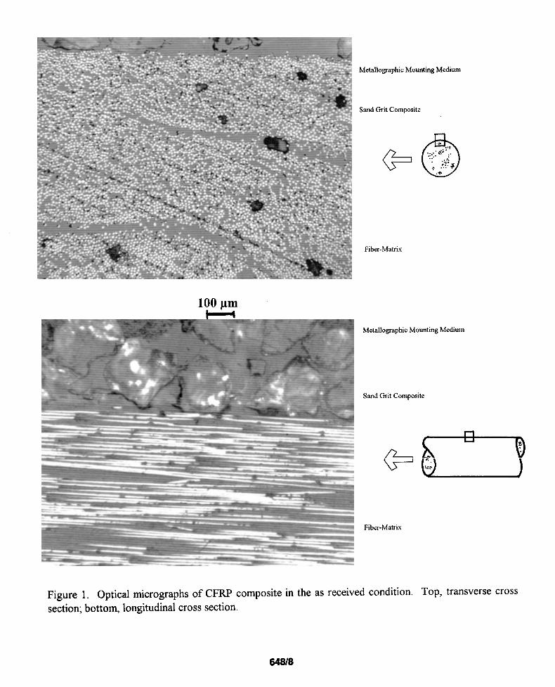
The CFRP composite used was a rod shaped pultruded carbon fiber composite -6 mm diameter. Thisrod was supplied as a 50,000 filament continuous tow by AKZO Industries, and is made from FORTAFIL@3(C) continuous carbon fiber (- 7 pm diameter). The fiber volume was approximately 53 Yo. The externalsurface of the rod was covered with a sand grit composite to enhance bond with concrete. Figure 1 showsoptical micrographs of longitudinal and transversely cross sections in the as received condition. Themechanical properties of the composite are summarized in Table 1,12
Steel Specimens
Steel used in this experiment was plain wire 5.5 mm in diameter (ASTM A 82) commonly used forspiral reinforcement in concrete. Metallographlc examination revealed a ferritic microstructure with lowcarbon (< O.10/0)content, The wire surface was sandblasted and degreased with acetone prior to casting inconcrete.
EXPERIMENTAL PROCEDURE
Sample Preparation
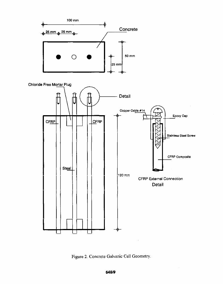
Eighteen reitiorced concrete prisms 5 x 10x 19 cm were used as galvanic cells (See Table 2 for mixdesign), All the prisms were contaminated with chloridesby adding 3% NaCl by weight of cement at the timeof mixing. Two CFRP specimens and one steel specimen were cast in each cell. Each rod (CFRP or steel)had a 19 cm length (32 cmz)in contact with the concrete. Figure 2 shows the cell configuration. Both endsof the steel wire were cast in a 2.5 cm diameter, 2.5 cm long chloride free mortar plug (w/c = O.5) to avoidcorrosion at the exit points. Furthermore, the steel and the mortar at the exit points were sealed with epoxy.The plugs were allowed to cure for 7 days before placement in the prism mold.
The CFRP specimens used in this experiment were tested in the following conditions: S1, with the sidesutface in the initial,as-received conditiory SDO1, with side sutiace mechanically degraded by filing off O.10/0
of the surface layer of the CFRP composite, and SD10 with 1°/0 of the surface layer removed. The filingmarks were typically 1 mm wide, 2 mm long and 0.5 mm deep, uniformly spaced and in sufficient numbers
648/2
to reach the percentage damage specified. These sutiace conditions were examined to determine thedifference in electrochemical action of as-received surface with grit composite vs damaged grit compositeand exposed fibers, Mechanical damage at the lateral surface may happen in actual construction practice,during handling, placing and casting of the composite in concrete structural members.
Individual electrical connections of both steel and CFRP specimens were made to external wiring. CFRPcontact resistances of< 1Q were achievedwith 9 mm long galvanized or stainless steel screws placed insidea drilled-and-tappedhole in one of the CFRP ends. A copper cable was attached to the screw, Afler placing5 mm of the screw inside the CFRP, a carbon conductive paint film was applied to the connection, to ensureelectrical continuity of the entire CFRP composite. An epoxy coating encased the connection to avoidpossible moisture-induced external galvanic effects.
The experiments (all at 22+20C) involved six consecutive stages:a. A curing stage in which the concrete prisms were cast and wet cured for 30 days (the CFRP and steel
specimens were not interconnected).b, A stabiliition stage, in which the prisms were then divided into groups and placed in three different
R.H. chambers (-95 YOR.H., -80 % R.H., and -60 % R.H.). The duration of this stage wasapproximately 40 days.
c. First coupling stage, where the prisms remained in their respective chambers and one CFRP rod waselectrically connected with the steel rod in each prism, for a period of 80 days. In this stage theCFRP/steel surface area ratio was 1:1.
d. A first uncoupling stage, from day 150 trough day 200, in which CFRP and steel were disconnectedand allowed to depolarize.
e. A second coupling stage (from day 200 through day 425) in which the two CFRP specimens in eachconcrete prism were connected to the steel. The CFRP/steel surface area ratio in this stage was 2:1.
f. A final uncoupling stage, in which the galvanic couples were permanently disconnected for fitureinvestigation.
Potential and Galvanic Current Measurements
Potential measurements were periodically made using a 200 Mt2 impedance DC voltmeter. Theywere measured versus a copper-copper sulfate electrode (CSE) with the sensing tip placed on the top surfaceof the concrete prism. During the coupling stages (c) and (e), the potentials of the CFRP and steel specimenswere measured in the “instant-off’ condition to avoid errors due to ohmic potential drop in the electrolyte.A CMS1OOCorrosion Measurement System from Gamry Instruments, Inc., configured as a zero resistanceammeter (ZRA) was used to measure the galvanic currents between the CFRP and steel specimens duringcoupling stages (c) and (e).
Cyclic Polarization Tests
During stage (e), cyclic polarization tests were performed to qualitatively evaluate the ability of theCFRP to act as a cathode at potentials as low as -700 mV vs CSE. These experiments were made with aCMS1OOfrom Gamry Instruments Inc. with a Potentiostat/Galvanostat/ZRA.
The experiment started with a forward scan rate of 0,1 mV/see, towards cathodic potentials. The potentialof the sample was swept from the open circuit potential (E~, to the apex potential (defined as 500 mV morenegative than E~, where the scan direction was reversed. The reverse scan rate was also 0.1 mV/sec. Thesamplingperiod, or spacingbetween data points, was chosen to be 10 sec. The experiments were performed
643/3
using the steel rod as the counter electrode, one of the CFRP rods as the reference electrode, and the otherCFRP rod in the concrete prism as the working electrode The scan rate used was chosen based on previousexperiments done with the same CFRP composite in saturated calcium hydroxide (Ca(OH)z) solutions andmortars.13From those results it was concluded that scan rate effects where not overwhelming at rates <0,25mV/sec.
The test results were IR compensated by subtracting the product of the effective concrete resistance14(measured at -100 Hz using the three-electrode configuration) and the applied current, from the potentialmeasured at the reference electrode.
RESULTS AND DISCUSSION
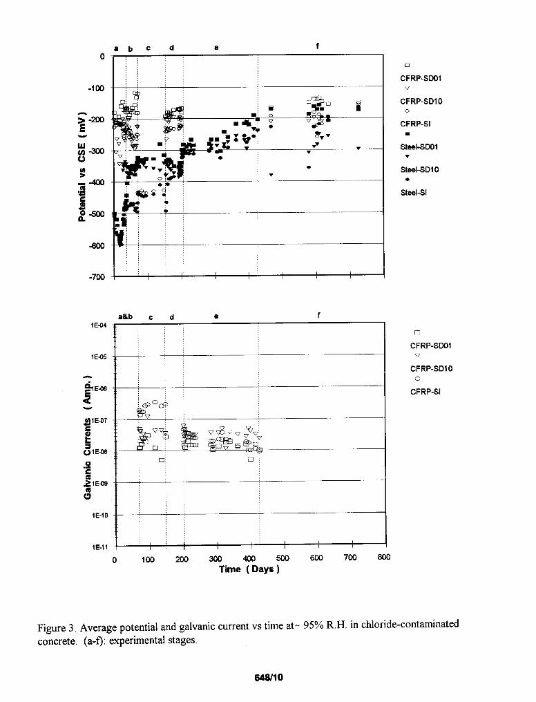
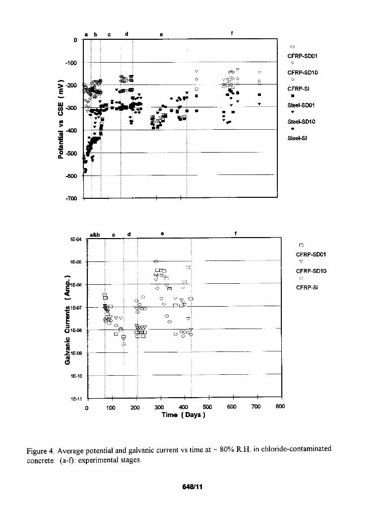
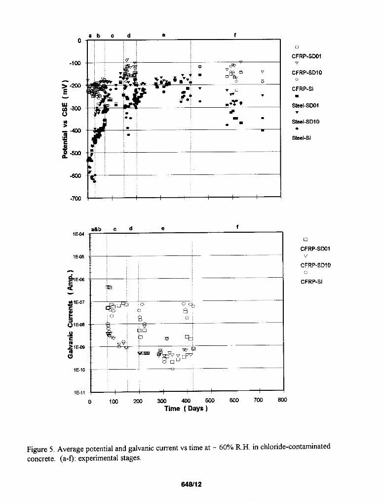
Figures 3-5 show the potentials and galvanic currents (average of two specimens) as a fhnction oftiie for each of the three R.H. environments. The vertical lines delimit the consecutive exposure stages (a)through (f) as indicated above each graph, The following observations and comments apply:
Curing, Stabilization and Uncoupled Stages
CFRP potentials before galvanic coupling with steel were typically -200 mV +100 mV CSE for allsurface conditions and R.H. regimes. Somewhat more positive potentials were observed during the laterstages of uncoupling (d,f).
Steel potentials were quite negative (=-600 mV CSE) during the curing stage and =-350 mV CSE averagein the stabilization stage. In the later uncoupled periods steel potentiak increased to more positive valuesbut still typically 100 mV to 200 mV more negative than those of the CFRP. The potential values (andspontaneous fluctuations) in all three humidity regimes were characteristic of actively corroding steel, 15asexpected from the high chloride ion content of the concrete.
Coupling Stages
In all cases, the steel acted as the anode in the galvaniccouple, The galvanic currents spanned a widerange, fi-omthe instrument detection limit (<0.1 nA) up to 10 vA. Considerable galvanic current fluctuationexisted as a fimction of time, especially in the 800/0and 60°/0R.H, regimes. When coupled, the potentials ofboth steel and CFRP were quite close, appeared to continue the trend of the steel during the uncoupledstages, and were more negative than those of the CFN during the Uncowled stages
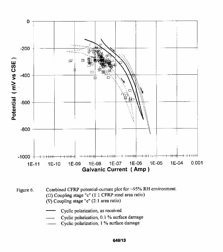
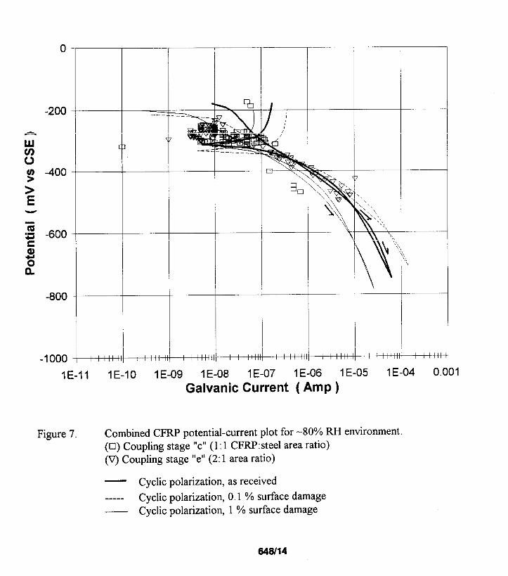
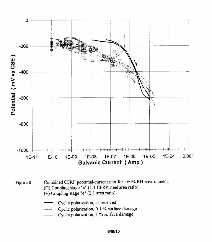
The combined graphs of Figures 6-8 were made by cross-plotting the individualpotential and galvanic currentvalues from each specimen hktory, during stage c (open rectangles) and stage e (open triangles), in themanner of a polarization diagram. The results indicate a correlation between the spontaneous variations inthe steel-composite potential and the observed galvanic currents (higher currents when the potential is morenegative). These observations, plus those mentioned earlier, strongly suggest that the steel dominated thepotential of the galvanic couple.
The highest galvanic current values (10 pA) observed were for the 80’XOR.H. environment during stage (e),when the steel potential experienced potential excursions approachkg -500 mV CSE (see Figure 7). Thehighest galvanic currents for the 95% R.H. environments (Stage (c)) was< 1 PA even though the potentialreached almost -600 mV CSE (see F@re 6). The highest currents were below 1.5 PA in the 60°/0R.H. tests
648/4
(see Figure 8), for which the potential tended not to be as negative as in the other environments (>-450 mVCSE). The magnitude of the galvanic currents may be expected to be greater during stage “e” (2:1CFRP/steel area ratio) than during stage “c” (1:1 ratio). A few results (for example for 80% R.H, atpotentials s-400 mV, Figure 7) appear to support that expectation, but the overall data set could not clearlydifferentiate between both area ratio regimes.
Cyclic Polarization
The results of the CFRP cyclic polarization tests are superimposed on the combined polarizationdiagrams of Figures 6-8, For clarity, results for only one of a duplicate set of tests are shown; the duplicatesyielded essentially the same conclusions. There was no consistent differentiation between the results fordifferent surface conditions, Relatively little hysteresis is apparent in the 95% and 80% R.H. tests. For allthe environments, the cathodic currents obtained in the cyclicpolarization tests are comparable to those fromthe combined long term behavior at the same potentials,
The tests at 95% R.H. show an apparent limiting current behavior at .1-10 wA,whereas at 80’%R.H. thelimitation (if any) develops at much higher currents, The polarization behavior suggests that the galvaniccurrent corresponded to a cathodic reaction on the CFRP surface, which in concrete is likely to result fromoxygen reduction. 1s-]6 This interpretation would agree with limiting current behavior at gs~. R.H. (sincelow oxygen diffhsivity is expected in nearly water-saturated concrete]’), and mostly activation-limitedpolarization at 80% R.H. when oxygen difisivity should be higher. The results from the tests at 60?’0R.H.,while less conclusive because of pronounced hysteresis, seem to fiuther support that view.
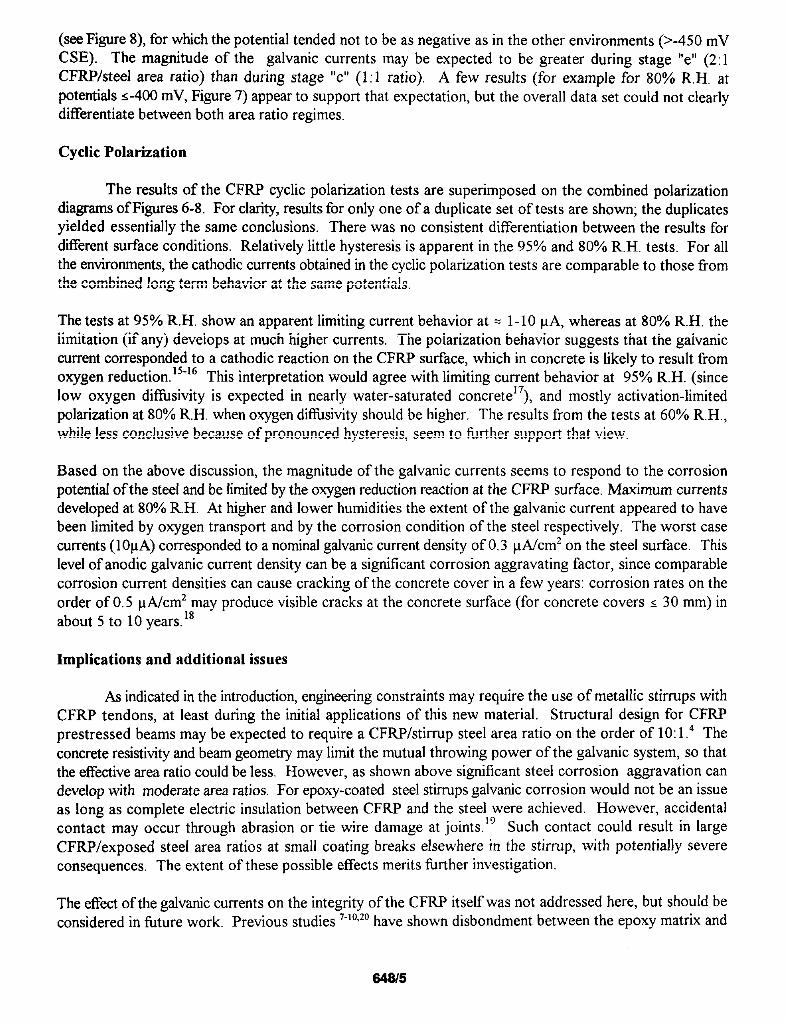
Based on the above discussion, the magnitude of the galvanic currents seems to respond to the corrosionpotentirdof the steel and be limitedby the oxygen reduction reaction at the CFRP surface, Maximum currentsdeveloped at 80% R.H. At higher and lower humidities the extent of the galvanic current appeared to havebeen limited by oxygen transport and by the corrosion condition of the steel respectively. The worst casecurrents (1OVA)corresponded to a nominalgalvanic current density of 0.3 @Jcm2 on the steel surface. Thislevel of anodic galvanic current density can be a significant corrosion aggravating factor, since comparablecorrosion current densities can cause cracking of the concrete cover in a few years: corrosion rates on theorder of 0,5 @/cm2 may produce visible cracks at the concrete surface (for concrete covers s 30 mm) inabout 5 to 10 years. 18
Implications and additional issues
As indicated in the introduction%engineering constraints may require the use of metallic stirrups withCFRP tendons, at least during the initial applications of this new material. Structural design for CFRPprestressed beams maybe expected to require a CFRP/stirrup steel area ratio on the order of 10:1.4 Theconcrete resistivityand beam geometry may limit the mutual throwing power of the galvanic system, so thatthe effective area ratio could be less. However, as shown above significant steel corrosion aggravation candevelop with moderate area ratios. For epoxy-coated steel stirrupsgalvanic corrosion would not be an issueas long as complete electric insulation between CFRP and the steel were achieved. However, accidentalcontact may occur through abrasion or tie wire damage at joints. 19 Such contact could result in largeCFRP/exposed steel area ratios at small coating breaks ekewhere in the stirrup, with potentially severeconsequences. The extent of these possible effects merits further investigation.
The effect of the galvanic currents on the integrity of the CFRP itself was not addressed here, but should beconsidered in fiture work. Previous studies 7-10’20have shown disbandment between the epoxy matrix and
&1815
the carbon fiberswhen the CFRP is catholically polarized in chloride contaminated solutions, A subsequentphase of this investigation is examining the extent of those effects in concrete.
CONCLUSIONS
1. Galvanic coupling between CFRP and steel in chloride contaminated concrete produced anodiccurrents on the steel. The galvanic current was greatest at intermediate R.H, levels. The highestnominal steel current densities were 0.3 pA/cm2, when the concrete was exposed to an 80°/0R.H.environment with a CFRP:steel area ratio of 2:1,
2. The steel dominated the potential of the galvanic couple. The cathodic current on the CFRP wasinterpreted as corresponding to oxygen reduction, showing signs of concentration polarization at 95°/0
R,H. and potentials more negative than -400 mV CSE.
ACKNOWLEDGMENTS
The authors are indebted to the University of South Florida for partial support of this investigation. Theopinions and findingsin this paper are those of the authors and not necessarily those of the funding agencies.One of the authors (A.A,T.A) acknowledges the scholarshipprovided by the National Council of Science andTechnology (CONACYT-Mexico).
1,
2,3.
4.5.
6.7,8.9.
10.11.
12.13.
14.
REFERENCES
K.K. Sagoe-Crentsil and F.P. Glasser, A4ag. Cone. Res,, 41, 149(1989): p. 205,R.S. Barneyback and S. Diamond, Cem. and Cone. Res., 11, 2(1981): p. 279.CD. Newhouse and R.E. Weyers, Techniques to Assess the Corrosion Activity of Steel ReinforcedConcrete Structures, STP 1276, (Philadelphia, PA: ASTM, 1996), p. 3.S.H, Rizkalla and G. Tadros, Concrete International, 16, 6(1994): p. 42.P.K, A4allic~Fiber-Reinforced Composites: Materials, Manufacturing md Design (New York, NY:Marcel Dekker, Inc., 1988).WC. Tucker, R, Brown and L. Russell, J. of Composite Mats., 24, (1990): p. 92.D, Kaushik, M.N. Alias and R. Brown, Corrosion, 47, 11(1991): p. 859.M.N. Alias and R. Brown, Corrosion, 48, 5(1992): p. 373.D,M. Aylor, High temperature and Environmental Effects on Polymeric Composites, STP 1174(Philadelphia PA: ASTM, 1993), p. 81.S.R. Taylor, F.D. Wall and G.L. Cahen, J. Electrochem. Sot., 143, 2(1996): p. 449.AA. Torres-Acost%A.A. Sa@es and R. Sen, Proceedings of the Second International Conferenceon Advanced Composite Materials in Bridges and Structures (Montreal, Canada: ACMBS-11, 1996),p. 141.AKZO, Technical Data Sheet 902A, Fortafil Fibers, Inc., Rockwood, TN 37854, 1994.AA. Torres-Acosta, “Polarization Behavior of Carbon Fiber-Reinforced Plastic Strands used inPrestressed Concrete,” IV International Conference on Advanced Materials, invited paper, posterpresentation, (Mexico City, Mexico, 1995).S,G. Millard, Proc. kstn. Civ. Engrs,, Part 2,91, Mar, (1991): p. 71.
646/6
15. A. Aguilar, A.A. Sagiies, and R,G. Powers, Corrosion Rates of Steel in Concrete, STP 1065,
(Philadelphia, PA: ASTM, 1990), p, 66.
16. C, Andrade, C. Alonso and A.M. Garcia, Advances in Cenr. Res., 3, 11(1990): p. 127.
17. O.E. Gjorv, O. Vennesland and A.H.S. E1-Busaidy, Mater. Pe@orm., 25, 12(1986): p. 39,18. C. Andrade, C. Alonso and F.J. Molina, Mats. and Structs., 26, (1993), p. 453,19. AA. Sagties, “Corrosion of Epoxy Coated Rebar in Florida Bridges,” Final Report to Florida D.O.T.,
WPI No. 0510603, May, 1994 (Available from FDOT Research Center, Tallahassee, FL).20. S,R. Taylor, Comp. Inter$, 2, 6(1994), p.403,
TABLE 1Carbon Fiber and Composite Properties (from manufacturer specs).
Material Properties
Tensile Strength
Tensile Modulus
Ultimate Elongation
Density
Cross Section Area
Filament Diameter
Axial Thermal Expansion
Carbon Fiber
3,800 MPa
227 GPa
1.’7’?J’o
1.8 g/cm3
4.3xI0-5 mm2
7,3 pm
-O.lpnhnl”c
Composite
TABLE 2Mix Proportions for Concrete Prisms
1,450 MPa
121 GPa
1.5?”0
29.7 mmz
25 pmlml°C
Material
Type I Portland Cement
Water
Fine Aggregate(Silica Sand)
Coarse Aggregate(Limestone, 1 cm max. size)
Calculated Total Cl-Concentration
Content (kg/m3)
391
177
776
866
14
am
MetallographicMounting Medium
Sand %]t Composite
Fiber-Matrix
MetallographicMounting Medium
Sand CM Composite
Fiber-Matrix
Figure 1. Optical micrographs of CFRP composite in the as received condition. Top, transverse cross
section; bottom, longitudinal cross section.
648/8
100 mm
I
,i.25mmA 25 mm ~
1
Concrete
/
ChlorideFreeMork—
T
1
30 mm
o- Detail
Copper Cable #l 4
%
}
f
Epoxy Cap
//.,/
//
1-Stainless Steel Straw
CFRP Compoalta
CFRPExternal Connection
Detail
Figure 2. Concrete Galvanic Cell Geometry
64819
-700
1E-04
1E-M
abed e f
,:,,
sRh . A a f
u
CFRP-SDOIv
CFRP-SDIOo
CFRP-SIm
Steel-SDOlv
Steel-SDl O.
Steel-sl
u
CFRP-SDO1v
CFRP-SDIO0
CFRP-SI
Figure 3, Average potential and galvanic current vs time at- 95% R.H, in chloride-contaminated
concrete. (a-f): experimental stages.
648/10
abc d e f
.
\&b C d e f:: :,,
:,;:r I I
o loo200300@3~Time ( Days)
Figure 4. Average potential and galvanic current vs time atconcrete, (a-~: experimental stages.
0
CFRP-SDOIv
CFRP-SD1O0
CFRP-SI■
steel-sDolv
&eel-SDIO●
Steehsl
n
CFRP-SLX31v
CFRP-SDIO0
CFRP-SI
600 7W 600
80’?AoR,H. in chloride-contaminated
648/11
o
-1co
~ -200
-700
.:9 .
.=
::
❑
CFRP-SDOIw
CFRP-SDIO0
CFRP-SIm
sted-soolv
Steel-SDl O●
Steel-sl
o
CFRP-SDOIv
CFRP-SDIOo
CFRP-SI
Time ( Days)
Figure 5, Average potential and galvanic current vs time at - 60% R.H. in chloride-contaminated
concrete. (a-f): experimental stages.
648/12
o-
-200-
nwu)c)g -400-
>E
~-600-
za5n
-800-
-1000-
.—
_______
m
[
H
T
I1 I
—
H
1E-11 IE-10 1E-09 1E-08 1E-07 1E-06 1E-05 1E-04 0.001
Galvanic Current ( Amp)
Figure 6. Combined CFRP potential-current plot for -95Y0 RH environment.(0) Coupling stage “c” (1: 1 CFRP:steel area ratio)(V) Coupling stage “e” (2: 1 area ratio)
— Cyclic polarization, as received----- Cyclic polarization, 0.1 % surface damage
Cyclic polarization, 1 % surface damage
643/13
o
-200
nuu)ug -400
>Eu
7~ -600ca)%n.
-800
-1000
I
—
it
i
IE-11 IE-10 1E-09 1E-08 1E-07 1E-06 1E-05 1E-04 0.001
Galvanic Current ( Amp)
Figure 7. Combined CFRP potential-current plot for -80% RH environment.(n) Coupling stage “c” (1: 1 CFRP:steel area ratio)(V) Coupling stage “e” (2: 1 area ratio)
— Cyclic polarization, as received----- Cyclic polarization, 0.1 % surface damage
Cyclic polarization, 1 % surface damage
848114
t+
—
+ I
1E-11 IE-10 1E-09 ‘1E-08 1E-07 1E-06 1E-05 1E-04 0.001
Galvanic Current ( Amp)
Figure 8. Combined CFRP potential-current plot for -60% RH environment(o) Coupling stage “c” (1: 1 CFRP:steel area ratio)(V) Coupling stage “e” (2: 1 area ratio)
— Cyclic polarization, as received----- Cyclic polarization, 0.1 % surface damage
Cyclic polarization, 1 % surface damage
548/15