paper recent advances in biometric recognition
TRANSCRIPT

Paper
Recent Advances in Biometric Recognition
Koichi Ito (member)†, Takafumi Aoki (member)†
Abstract This paper presents recent advances in biometric recognition, where we focus on face, fingerprint and iris
recognition, which are major research topics on biometric recognition. We summarize the research trend of face, fingerprint
and iris recognition over the past decade. This paper also presents our activities of biometric recognition. Our approach
employs the phase information obtained by Discrete Fourier Transform (DFT) of images. The phase information preserves
the inherent features of the image, and its correlation function, called phase correlation or Phase-Only Correlation (POC),
gives us both the good similarity measure for biometric recognition and the translational displacement for image registration.
Our approach of using phase information has been successfully applied to fingerprint, face, iris, palmprint, finger knuckle and
dental recognition. Among them, we present some interesting results of palmprint recognition, finger knuckle recognition and
dental recognition.
Key words: biometrics, face recognition, fingerprint recognition, iris recognition, palmprint recognition, finger knuckle recognition,
disaster victim identification, phase-only correlation
1. Introduction
Biometric authentication (or simply biometrics) is to
identify a person based on the physiological or behav-
ioral characteristics1)2) such as fingerprint, face, iris,
voice, signature, etc. Biometrics has attracted exten-
sive attention as a new authentication approach against
traditional ones such as key, password, etc. Biometric
traits are not stolen and forgotten compared with key,
card and password. Therefore, biometrics techniques
provide us better security and greater convenience than
traditional person authentication techniques. Practical
person authentication systems using fingerprint, face,
iris, etc. have been commercially available and used in
access control, ATM, etc.
Jain et al.3) summarized what biological measure-
ments qualify to be a biometric trait. They introduced
the following requirements to use physiological or be-
havioral characteristic as a biometric trait:
• Universality: each person should have the charac-
teristic.
• Distinctiveness: any two persons should be suffi-
ciently different in terms of the characteristic.
• Permanence: the characteristic should be suffi-
ciently invariant over a period of time.
• Collectability: the characteristic can be measured
Received ; Revised ; Accepted
†Graduate School of Information Sciences, Tohoku University
(6-6-05, Aramaki Aza Aoba, Sendai, 980-8579, Japan.)
quantitatively.
They also presented some issues to be considered in a
practical biometric system:
• Performance, which refers to the achievable recog-
nition accuracy and speed, the resources required to
achieve the desired recognition accuracy and speed, as
well as the operational and environmental factors that
affect the accuracy and speed.
• Acceptability, which indicates the extent to which
people are willing to accept the use of a particular bio-
metric trait in their daily lives,
• Circumvention, which reflects how easily the sys-
tem can be fooled using fraudulent methods.
Biometric techniques to be used in the practical sys-
tem depend heavily on application requirements. The
above seven factors can be used to compare biomet-
ric techniques as shown in Table 1, which was derived
on the perception of Jain et al3). This table provides
us good suggestions when we consider which biomet-
ric techniques are selected in practice. Let us focus on
performance and collectability of biometric traits. A
face has low performance due to weakness against envi-
ronmental variations, while it is easy to capture a face
by a camera. An iris has high performance due to its
distinctive texture pattern, while an iris image is cap-
tured by a special imaging device. A face is suitable
for low-security level application such as PC login be-
cause of its high collectability. On the other hand, an
iris is suitable for high-security level application such as
immigration control because of its high performance, al-
ITE Trans. on MTA Vol. 6, No. 1, pp. 64-80 (2018)
64
Copyright © 2018 by ITE Transactions on Media Technology and Applications (MTA)
Received July 19, 2017; Revised October 4, 2017; Accepted October 11,2017

Table 1 Comparison of various biometric techniques on the perception of Jain et al.3), where H, M and
L indicate High, Middle and Low, respectively.
Universality Distinctiveness Permanence Collectability Performance Acceptability Circumvention
DNA H H H L H L L
Ear M M H M M H M
Face H L M H L H H
Facial thermogram H H L H M H L
Fingerprint M H H M H M M
Gait M L L H L H M
Hand geometry M M M H M M M
Hand vein M M M M M M L
Iris H H H M H L L
Keystroke L L L M L M M
Odor H H H L L M L
Palmprint M H H M H M M
Retina H H M L H L L
Signature L L L H L H H
Voice M L L M L H H
though a special imaging device is required to capture
iris images. Performance can be complemented with
combining multiple biometric traits such as face and
iris to keep both high performance and high collectabil-
ity. This approach is known as multimodal biometrics4),
which is one of active research topics in biometrics.
Table 2 summarizes the number of papers for each
biometric trait presented in the international confer-
ences related to biometrics, where the number of pa-
pers was counted by the authors. This summary pro-
vides us the research trends in the field of biometrics
over the past 13 years. Researches on face, fingerprint
and iris are always hot, since the number of their pa-
pers is constantly large and is always more than other
biometric traits. A face is a major research topic in
many fields such as computer vision, pattern recog-
nition, image processing and biometrics. A variety
of face image processing methods has been proposed,
since the performance of face image processing is sig-
nificantly influenced by environmental changes such as
head pose, expression and illumination changes. A new
research topic on fingerprint recognition has been ex-
plored, since minutiae-based matching exhibits suffi-
cient performance on fingerprint recognition and practi-
cal fingerprint recognition systems have been developed.
Latent fingerprint recognition is one of the new topics,
which requires new preprocessing methods such as fin-
gerprint segmentation, ridge enhancement and minutiae
extraction specially designed for latent fingerprint im-
ages. A new research topic on iris recognition has been
explored as well as fingerprint recognition, since iriscode
is the first choice of iris recognition because of its high
recognition performance. The purpose of iris recogni-
tion is changed from a person to pedestrians from the
viewpoint of surveillance applications. Therefore, oc-
ular recognition, which uses the surrounding region of
the eye for biometric recognition, is considered as a new
topic instead of iris recognition, since iris recognition at
a distance is a difficult problem.
Figure 1 shows a flow diagram of a standard bio-
metrics system. Note that we assume an image-based
system for a brief description in the following. This sys-
tem consists of 5 components: (i) sensing, (ii) prepro-
cessing, (iii) feature extraction, (iv) database and (v)
matching. In the sensing step, an image of a biometric
trait is captured using a sensor. For example, a cam-
era is used in face, palmprint, finger knuckle and gait
recognition and a special sensor is used in iris, signature
and vein recognition. Preprocessing consists of a set
of image processing methods such as contrast enhance-
ment, noise removal, geometric transformation, Region
Of Interest (ROI) extraction, etc. The performance of
preprocessing is important for the subsequent step of
feature extraction, since the captured image usually in-
cludes unnecessary background components for biomet-
ric recognition. In the feature extraction step, features
to be matched are extracted from an ROI image, which
is the most active topic in biometric recognition. Local
features are designed depending on the type of biomet-
ric traits in the most cases. Database stores registered
features for the matching step. In the matching step,
a similarity or a dissimilarity between registered and
input features is calculated to make a final decision.
Each component is a major research topic on biomet-
rics. In addition, there are other research topics con-
sidered in the biometric system such as anti-spoofing,
template protection, cancelable biometrics and multi-
modal biometrics from the viewpoint of system security.
As mentioned above, biometrics is a kind of multidisci-
plinary research fields and a variety of methods of com-
65
Invited Paper » Recent Advances in Biometric Recognition

Table 2 Research trends in the international conferences on biometrics, where the number of papers
provides us the research trends in the field of biometrics. ICBA: International Conference on
Biometric Authentication, ICB: International Conference on Biometrics, IJCB: International
Joint Conference on Biometrics.
ICBA 2004 ICB 2006 ICB 2007 ICB 2009 IJCB 2011 ICB 2012 ICB 2013 IJCB 2014 ICB 2015 ICB 2016
Face 30 27 41 44 44 25 24 21 27 18
Voice 8 3 6 10 2 3 1 0 1 0
Fingerprint 23 19 21 11 14 11 11 14 14 13
Palm 3 2 4 6 3 3 2 1 5 2
Multimodal 10 7 8 24 16 4 1 3 1 0
Gait 0 3 5 6 7 2 2 2 2 3
Iris 11 18 12 12 6 16 13 16 7 9
Signature 13 4 10 4 4 0 5 1 3 0
Others 6 21 17 8 14 17 13 18 11 7
puter vision, pattern recognition and image processing
techniques are required to develop a reliable and high-
performance biometrics system, although biometrics is
essentially a pattern recognition problem.
This paper presents recent advances in biometric
recognition, where we focus on face, fingerprint and
iris recognition, which are major research topics on bio-
metric recognition. We summarize the research trend
of face, fingerprint and iris recognition over the past
decade. This paper also presents our activities of bio-
metric recognition. Our approach employs the phase
information obtained by Discrete Fourier Transform
(DFT) of images. The phase information preserves the
inherent features of the image, and its correlation func-
tion, called phase correlation or Phase-Only Correla-
tion (POC), gives us both the good similarity measure
for biometric recognition and the translational displace-
ment for image registration. Our approach of using
phase information has been successfully applied to fin-
gerprint, face, iris, palmprint, finger knuckle and dental
recognition. We provide a brief introduction of our re-
search results of palmprint recognition, finger knuckle
recognition and dental recognition, which are interest-
ing, practical and useful in the field of biometrics.
2. Face Recognition
This section describes the research trend in face
recognition. Figure 2 shows a standard flow diagram
of face recognition systems, which consists of 4 steps:
(i) face detection, (ii) normalization, (iii) feature ex-
traction and (iv) matching. We summarize the techni-
cal advances in each step and present recent research
topics on face recognition.
2. 1 Face Detection
Face detection, which is the first process of face recog-
nition, extracts a face region from an input image. The
accuracy of face detection is important especially for
face recognition at a distance such as surveillance ap-
plication, since there are multiple faces with different
size in an image captured by a surveillance camera.
The most famous method was proposed by Viola et
al.5), which is also called the Viola-Jones method. This
method first extracts Haar-like features from an image,
where the integral image is used for fast Haar-like fea-
ture extraction. Next, a variant of AdaBoost is used
to select the best features and to train classifiers. A
strong classifier is obtained by constructing a cascade of
weak classifiers to boost the classification performance
of simple classifiers. In the training, a huge number of
face and non-face images are required to make a good
face detector. The Viola-Jones method with trained
classifiers is available in OpenCV∗, which is a famous
computer vision library. The OpenCV implementation
of the Viola-Jones method is a de-facto standard, since
users do not need a time-consuming training to make a
face detector.
The use of the Viola-Jones method makes it possi-
ble to detect near frontal faces from an image. Face
detection in real-world applications has to take into ac-
count the unconstrained conditions such as large pose
and expression changes, large occlusions, illumination
changes, etc. and is still one of the most studied topics
in computer vision∗∗. We introduce one of the state-
of-the-art studies of face detection. Yang et al. cre-
ated a face detection benchmark dataset, which is called
the WIDER FACE dataset∗∗∗. The WIDER FACE
dataset consists of 393,703 labeled face bounding boxes
in 32,203 images. Images in the dataset have a high de-
gree of variability in scale, pose, occlusion, expression,
appearance (makeup) and illumination. Yang et al.
proposed the baseline face detection method using Con-
volutional Neural Network (CNN)7), where this method
employs the multi-scale cascade CNN to deal with large
∗ OpenCV: http://opencv.org/∗∗ Please refer to the literature6) for the detailed survey of the re-
cent face detection methods.∗∗∗ WIDER FACE: http://mmlab.ie.cuhk.edu.hk/projects/WIDERFace/
ITE Trans. on MTA Vol. 6, No. 1 (2018)
66

Biometric trait Sensing Preprocessing Feature
extraction Database
Matching Genuine/ImpostorBiometric trait Sensing Preprocessing Feature
extraction
Anti-spoofing
Cancelable biometricsTemplate protection
Multimodal biometrics
Enrollment
Verification
Fig. 1 Flow diagram of a standard biometrics system and research topics.
Face image
Face detection Normalization Feature
extraction MatchingGenuine
or Impostor
Database
Fig. 2 Flow diagram of a general face recognition system.
scale variations of faces. They also compared the face
detection accuracy of the proposed method with four
representative methods. Using such a large-scale face
image dataset, a lot of face detection methods using
a deep learning approach has been proposed in recent
years.
2. 2 Normalization
Face images have to be normalized in terms of head
pose and expression in order to exhibit good recogni-
tion performance. This process is important to deal
with face images under the unconstrained conditions.
In general, landmarks are detected on a face and are
used to normalize head pose and expression. One of the
famous landmark detection methods is Active Appear-
ance Model (AAM) proposed by Cootes et al.8). AAM is
a parametric face model of both landmarks and texture,
which is derived by using Principal Component Analy-
sis (PCA). The demo software is available on the web∗.AAM cannot handle a large head pose change, since
head pose changes are essentially 3D transformation.
On the other hand, a 3D face model, which is called
3D Morphable Model (3DMM), has been proposed by
Blanz et al.9). 3DMM can handle a large head pose
change, while this method requires a lot of 3D face mod-
els in the training. Nowadays, it is easy to capture 3D
face data and process them because of advances in com-
∗ aam tools: http://personalpages.manchester.ac.uk/staff/timothy.
f.cootes/software/am_tools_doc/index.html
puter technology. Large Scale Facial Model (LSFM)
has been created from a large scale dataset by Booth
et al.10), where the dataset includes face images and 3D
data captured from 9,663 subjects. LSFM is a para-
metric 3D facial model of head pose, facial expression,
age and ethnicity. The source code of LSFM is avail-
able on the web∗∗. The use of such parametric 3D face
models makes it possible to deal with faces under the
unconstrained conditions.
2. 3 Feature Extraction and Matching
Feature extraction and matching are core processes
of face recognition. The traditional methods employ
PCA, Independent Component Analysis (ICA) and
Linear Discriminant Analysis (LDA)11), where such a
feature is represented as a point on the subspace in
PCA, ICA, and LDA. PCA-based method is known
as Eigenface12) and LDA-based method is known as
Fisherface13). Other methods employ subspace meth-
ods such as CLAss-Featuring Information Compression
(CLAFIC) method14), subspace method14), mutual sub-
space method and its extensions such as constrained
mutual subspace method15), and multiple constrained
mutual subspace method16), etc., where such a fea-
ture is represented as a set of bases of the subspace.
The approaches mentioned above transform the high-
dimensional image space into the low-dimensional sub-
spaces and provide good representation and good dis-
∗∗ LSFM: https://github.com/menpo/lsfm
67
Invited Paper » Recent Advances in Biometric Recognition

crimination for face recognition by selecting effective
subspaces. The drawback of such approaches is that
position and intensity of all the face images have to be
aligned. Therefore, these approaches may exhibit good
recognition performance only for face images captured
under the desired condition.
Recently, Local Binary Patterns (LBPs) have been
proposed and applied to face recognition17). LBP is ob-
tained by thresholding neighborhoods of each pixel with
the center pixel value, and then the histogram of LBPs
is used as a texture descriptor. So far, the improved
versions of the LBP-based method have been proposed
and been applied to various biometric recognition prob-
lems. LBP has the versatility for image matching and is
applied to solve computer vision problems18), since LBP
does not need any optimization process. On the other
hand, LBP cannot handle large deformation of images
and also may not exhibit the comparable performance
with the other methods specified to each biometric trait
due to its versatility. The original implementation of
LBPs is available on the web∗.The deep learning-based approach has a significant
impact on face recognition researchers. The face im-
age dataset called Labeled Faces in the Wild (LFW)∗∗
is known as one of difficult face image datasets, since
this dataset is designed for studying the problem of un-
constrained face recognition. Taigman et al.19) employ
CNN to extract features to be matched. Their CNN
model, which is called DeepFace, is trained using a
large-scale face dataset collected from Facebook, where
the number of face images is 4.4 million captured from
4,030 persons. The recognition accuracy of DeepFace is
97.35%, while that of human is 97.53%. The deep learn-
ing approach achieved a breakthrough in face recogni-
tion, since the state-of-the-art methods exhibited the
recognition accuracy of about 90% at that time. Vari-
ous CNN models have been proposed for face recogni-
tion since DeepFace was proposed and their recognition
accuracy is comparable to a human quality.
2. 4 Face Attributes
Face recognition can be used for practical situations
because of the advent of deep learning as mentioned
above. The state-of-the-art methods of face recognition
exhibit comparable recognition performance of human
even for face images captured under the unconstrained
conditions such as large pose and expression changes,
∗ LBP software: http://www.cse.oulu.fi/wsgi/MVG/Downloads/
LBPSoftware∗∗ LFW: http://vis-www.cs.umass.edu/lfw/
large occlusions, illumination changes, etc.
Further performance improvement of face recognition
is to use face attributes. Various characteristics, i.e.,
face attributes, include in a face such as gender, hair,
skin color, eyeglass, shape, etc. The use of such infor-
mation makes it possible to classify face images accord-
ing to categories of face attributes in advance, resulting
in improving recognition performance and reducing the
computation time. This approach is known as soft bio-
metrics. Jain et al. defined that soft biometric traits as
characteristics that provide some information about the
individual, but lack the distinctiveness and permanence
to sufficiently differentiate any two individuals20).
The initial approach of predicting face attributes em-
ploys the statistical approach such as Bayesian21). It
is difficult to design feature descriptors for predicting
attributes, since there is a lot of types of attributes in-
cluded in a face, resulting in low accuracy of prediction.
Recently, the deep learning approach is applied to pre-
dict face attributes22). The use of deep learning makes
it possible to predict precise attributes from a face.
3. Fingerprint Recognition
This section describes the research trend in finger-
print recognition. Fingerprints are the most widely de-
veloped biometric traits and are used for person au-
thentication more than 100 years ago23). The finger-
print technology has already been put to practical use
in various applications from forensics to high-security
access. New issues on fingerprint recognition have been
explored until now, although the de-facto standard fin-
gerprint recognition algorithm is available.
Figure 3 shows a standard flow diagram of fingerprint
recognition systems, which consists of 4 steps: (i) seg-
mentation, (ii) enhancement, (iii) minutiae extraction
and (iv) matching. First, the area of a fingerprint is
extracted from an input image. This segmentation can
be done by simple image processing. Next, a finger-
print image is enhanced so as to extract minutiae accu-
rately. Ridges of a fingerprint can be enhanced using a
set of Gabor filters24). The Matlab code is available
on the web∗∗∗. Binarization and thinning are applied to
the enhanced fingerprint. Minutiae are extracted using
a simple coordinate model. A pixel corresponding to
minutiae is characterized by a crossing number, which
is defined by the sum of differences between pairs of
adjacent pixels in 8-neighborhood. The most common
∗∗∗ Matlab code: http://www.peterkovesi.com/matlabfns/index.
html#fingerprints
ITE Trans. on MTA Vol. 6, No. 1 (2018)
68

feature descriptor derived from minutiae information is
a triplet consisting of minutia location coordinates and
the minutia angle. In general, feature descriptor de-
fined by the geometric relationship among neighboring
minutiae is used to enhance robustness against finger-
print deformation25). The matching score is calculated
by the distance between feature descriptors of minutiae.
We present recent research topics on fingerprint
recognition in the following.
3. 1 Fingerprint Matching
A huge number of fingerprint matching algorithms
has been developed because of the existence of pub-
lic fingerprint image datasets and evaluation protocols.
One of the most famous fingerprint datasets is pro-
vided by Fingerprint Verification Competition (FVC)∗,where FVC was held in 2000, 2002, 2004 and 2006.
The book23) includes fingerprint image datasets used
in FVC2000, FVC2002 and FVC2004. FVC has been
renewed as a web-based automated evaluation system
for fingerprint recognition algorithms, which is called
FVC-onGoing∗∗. Fingerprint recognition algorithms
made rapid growing, since academic and industrial re-
searchers competed on recognition performance of fin-
gerprint recognition algorithms through FVC. Fierrez
et al.26) summarized fingerprint recognition algorithms
submitted to FVC 2004 and consider the combination
of algorithms to improve the performance of fingerprint
recognition. Recently, a new minutia matching algo-
rithms, called Minutiae Cylinder Code (MCC), was pro-
posed by Cappelli et al.27), which is used as a base-
line algorithm in FVC-onGoing. MCC describes a local
structure of each minutia. This descriptor encodes spa-
tial and directional relationships between the minutia
and its neighborhood, which is represented as a cylinder
whose base and height are related to the spatial and di-
rectional information, respectively. The SDK of MCC
is available on the web∗∗∗.3. 2 Latent Fingerprint Recognition
Latent fingerprints obtained from crime scenes have
been used in forensic identification more than a cen-
tury. The manual intervention of experts is still re-
quired for latent fingerprint verification, while the per-
formance of Automated Fingerprint Identification Sys-
∗ FVC2000: http://bias.csr.unibo.it/fvc2000/
FVC2002: http://bias.csr.unibo.it/fvc2002/
FVC2004: http://bias.csr.unibo.it/fvc2004/
FVC2006: http://bias.csr.unibo.it/fvc2006/∗∗ FVC-onGoing: https://biolab.csr.unibo.it/FVCOnGoing/UI/Form/
Home.aspx∗∗∗ MCC SDK: http://biolab.csr.unibo.it/
tems (AFISs) has been significantly improved with the
recent development of technology. The difficulty in la-
tent fingerprint recognition is mainly due to (i) poor
quality of ridge information, (ii) small finger area and
(iii) large nonlinear deformation28). Although minutiae
matching is also used in latent fingerprint matching, it
is significantly difficult to extract minutiae from latent
fingerprint images. Therefore, preprocessing methods
for latent fingerprint images such as segmentation, en-
hancement, minutiae extraction have been mainly pro-
posed29). Latent fingerprint matching has been still an
open problem in the field of fingerprint recognition be-
cause of its difficulty. There is a good survey paper for
latent fingerprint matching30). For more details, please
refer to this paper.
3. 3 Hand-based Biometrics
A hand has a lot of biometrics traits other than a
fingerprint. There are some relatively new biometric
traits in a hand such as palmprint, finger knuckle and
vein.
A palm is a large inner surface of a hand with many
features such as principle lines, ridges, minutiae, tex-
ture, etc., and is expected to be one of the distinctive
biometric traits31)32). Unlike a fingerprint, a palm image
can be captured using a camera under unconstrained
environments, resulting in realizing a user-friendly con-
tactless biometric recognition system. One of the pio-
neer researches on palmprint recognition was reported
by Zhang et al.33). They proposed a baseline palm-
print recognition method and created a palmrpint im-
age database∗4. In addition, some practical systems
using palmrpint recognition have been proposed such
as a palmprint recognition system for mobile phones34)
and a touchless palmprint recognition system35). There
is a good survey paper for palmprint recognition32)36).
For more details, please refer to these papers.
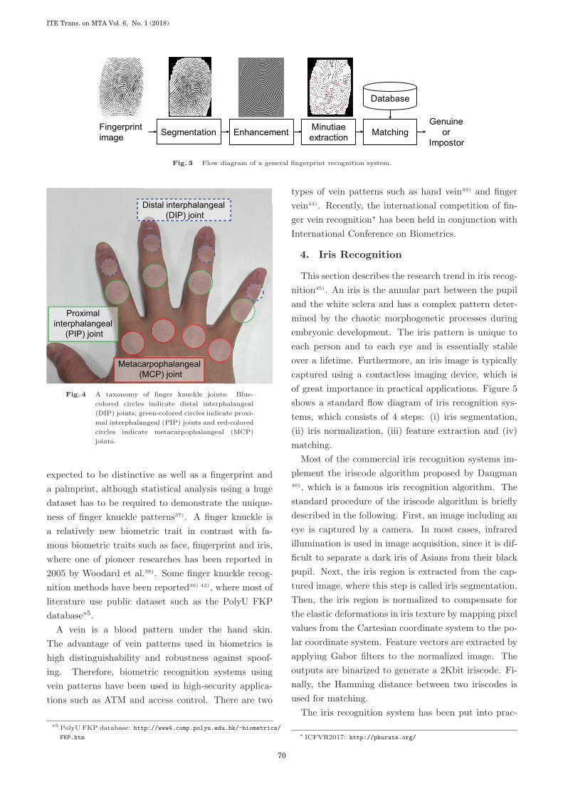
An outer surface of a finger has three knuckles: a
distal interphalangeal (DIP) joint, a proximal interpha-
langeal (PIP) joint and a metacarpophalangeal (MCP)
joint as shown in Fig. 4. Kumar et al.37) categorized
three finger joints into major and minor finger knuckles,
where a DIP joint is a first minor finger knuckle, a PIP
joint is a major finger knuckle and an MCP joint is a
second minor finger knuckle. It is easy to capture such
patterns on a finger knuckle by a camera. This advan-
tage allows us to develop a flexible and compact bio-
metric authentication system. A finger knuckle is also
∗4 PolyU Palmprint Database: http://www4.comp.polyu.edu.hk/
~biometrics/
69
Invited Paper » Recent Advances in Biometric Recognition
Fingerprint image Segmentation Enhancement Minutiae
extraction MatchingGenuine
orImpostor
Database
Fig. 3 Flow diagram of a general fingerprint recognition system.
Distal interphalangeal (DIP) joint
Proximal interphalangeal
(PIP) joint
Metacarpophalangeal (MCP) joint
Fig. 4 A taxonomy of finger knuckle joints: Blue-
colored circles indicate distal interphalangeal
(DIP) joints, green-colored circles indicate proxi-
mal interphalangeal (PIP) joints and red-colored
circles indicate metacarpophalangeal (MCP)
joints.
expected to be distinctive as well as a fingerprint and
a palmprint, although statistical analysis using a huge
dataset has to be required to demonstrate the unique-
ness of finger knuckle patterns37). A finger knuckle is
a relatively new biometric trait in contrast with fa-
mous biometric traits such as face, fingerprint and iris,
where one of pioneer researches has been reported in
2005 by Woodard et al.38). Some finger knuckle recog-
nition methods have been reported39) 42), where most of
literature use public dataset such as the PolyU FKP
database∗5.A vein is a blood pattern under the hand skin.
The advantage of vein patterns used in biometrics is
high distinguishability and robustness against spoof-
ing. Therefore, biometric recognition systems using
vein patterns have been used in high-security applica-
tions such as ATM and access control. There are two
∗5 PolyU FKP database: http://www4.comp.polyu.edu.hk/~biometrics/
FKP.htm
types of vein patterns such as hand vein43) and finger
vein44). Recently, the international competition of fin-
ger vein recognition∗ has been held in conjunction with
International Conference on Biometrics.
4. Iris Recognition
This section describes the research trend in iris recog-
nition45). An iris is the annular part between the pupil
and the white sclera and has a complex pattern deter-
mined by the chaotic morphogenetic processes during
embryonic development. The iris pattern is unique to
each person and to each eye and is essentially stable
over a lifetime. Furthermore, an iris image is typically
captured using a contactless imaging device, which is
of great importance in practical applications. Figure 5
shows a standard flow diagram of iris recognition sys-
tems, which consists of 4 steps: (i) iris segmentation,
(ii) iris normalization, (iii) feature extraction and (iv)
matching.
Most of the commercial iris recognition systems im-
plement the iriscode algorithm proposed by Daugman46), which is a famous iris recognition algorithm. The
standard procedure of the iriscode algorithm is briefly
described in the following. First, an image including an
eye is captured by a camera. In most cases, infrared
illumination is used in image acquisition, since it is dif-
ficult to separate a dark iris of Asians from their black
pupil. Next, the iris region is extracted from the cap-
tured image, where this step is called iris segmentation.
Then, the iris region is normalized to compensate for
the elastic deformations in iris texture by mapping pixel
values from the Cartesian coordinate system to the po-
lar coordinate system. Feature vectors are extracted by
applying Gabor filters to the normalized image. The
outputs are binarized to generate a 2Kbit iriscode. Fi-
nally, the Hamming distance between two iriscodes is
used for matching.
The iris recognition system has been put into prac-
∗ ICFVR2017: http://pkurate.org/
ITE Trans. on MTA Vol. 6, No. 1 (2018)
70

Iris image Segmentation Normalization Featureextraction Matching
Genuineor
Impostor
Database
Fig. 5 Flow diagram of a general iris recognition system.
tical use in high-level security applications due to the
high discrimination capability of iris texture. The im-
migration system using iris recognition has been already
introduced to provide automated clearance through UK
immigration. There are still unsolved problems in iris
recognition under unconstrained conditions and at a
distance, although the de-facto standard iris recognition
algorithm, i.e., iriscode, is available. We summarize re-
cent research topics on iris recognition in the following.
4. 1 Iris Segmentation
Iris segmentation is to extract the valid part of the iris
from the input image. The performance of iris recogni-
tion is heavily influenced by the accuracy of iris segmen-
tation. It is, however, difficult to perform accurate iris
segmentation under unconstrained conditions45). The
iris is often partially occluded by eyelids, eyelashes, and
shadows and is occluded by specular reflections when
the user wears glasses. The pupillary and limbic bound-
aries are noncircular. Other challenges of iris segmen-
tation include defocusing, motion blur, poor contrast,
oversaturation, etc. Iris segmentation needs to find the
pupillary and limbic boundaries of the iris, localize its
upper and lower eyelids if they occlude, and detect and
exclude any superimposed occlusions of eyelashes, shad-
ows, or reflections. The traditional approach of iris seg-
mentation employs circle fitting46), while this approach
cannot be used under unconstrained conditions. To
accurately segment the iris region depending on the
iris shape, Shar et al. used geodesic active contours
(GACs)47) and He et al. used an elastic model with
spline-based edge fitting48).
4. 2 Ocular Recognition
Iris recognition at a distance is considered to real-
ize high-level security in surveillance applications due
to its high discriminant capability compared with other
biometric traits. The competition for iris recognition
at a distance was held in 2008 by National Institute of
Standards and Technology (NIST), the United States,
which is called Multiple Biometric Grand Challenge
(MBGC)∗. The video sequence of a walking person cap-
tured with near-infrared illumination was used for iris
recognition in MBGC. There is no expected algorithm
submitted due to high difficulty in iris recognition such
as heavy motion blur, low resolution, poor texture, etc.
Addressing the above problem, an ocular image, which
is the surrounding region of the eye including the iris,
is used as a new biometric trait for the purpose of per-
son authentication at a distance with high-level secu-
rity49) 51). Person authentication using eye regions is
called ocular recognition or periocular recognition. In
the case of using ocular images, iris segmentation is not
required. Therefore, it is expected that ocular recogni-
tion can be used for recognizing pedestrians. NIST held
the competition of ocular recognition, which is called
Face and Ocular Challenge Series (FOCS)∗∗, to explore
new biometric recognition algorithms using ocular im-
ages. Although there has been some literature for ocu-
lar recognition52) 56), further improvement of algorithms
is required, since the recognition performance of these
algorithms is about 90% in the FOCS dataset.
5. Biometric Recognition Using Phase-
Only Correlation
This section presents our activities of biometric recog-
nition. We consider employing the phase information
obtained by DFT of images. The phase information
preserves the inherent features of the image, and its
correlation function, called phase correlation or POC,
gives us both the good similarity measure for biomet-
ric recognition and the translational displacement for
image registration. The image matching method us-
ing phase information called Band-Limited Phase-Only
Correlation (BLPOC) has been proposed57) to dedicate
POC to similarity measure. POC and BLPOC cannot
handle the nonlinear deformation of images, since the
∗ MBGC: https://www.nist.gov/programs-projects/
multiple-biometric-grand-challenge-mbgc∗∗ FOCS: https://www.nist.gov/programs-projects/
face-and-ocular-challenge-series-focs
71
Invited Paper » Recent Advances in Biometric Recognition
IrisFingerprint Dental X-ray imagePalmprint
Palmprintverification app
Iris verificationunit
2D/3D faceverification unit
Disaster victime identification software:Dental Finder
3D face2D faceFinger knuckle
Biometric recognition using phase-only correlation
Door security Fingerprint verification uint
Fig. 6 Application of phase-only correlation to biometric recognition.
phase information includes only translational displace-
ment. The approach combined with phase-based corre-
spondence matching58) and BLPOC has been proposed
to deal with nonlinear deformation59). So far, we have
applied POC techniques to various biometric recogni-
tion problems59) 63) as shown in Fig. 6. We summarize
(i) the importance of phase information in images, (ii)
fundamentals of POC, BLPOC, correspondence match-
ing and local phase features and (iii) applications to
some biometric recognition problems in palmprint, fin-
ger knuckle and dental in the following.
5. 1 The Importance of Phase Information in
Images
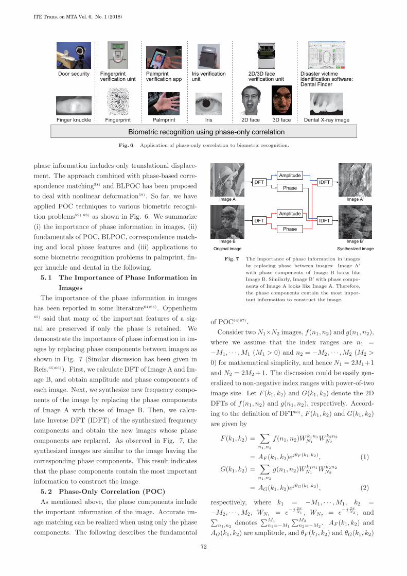
The importance of the phase information in images
has been reported in some literature64)65). Oppenheim65) said that many of the important features of a sig-
nal are preserved if only the phase is retained. We
demonstrate the importance of phase information in im-
ages by replacing phase components between images as
shown in Fig. 7 (Similar discussion has been given in
Refs.65)66)). First, we calculate DFT of Image A and Im-
age B, and obtain amplitude and phase components of
each image. Next, we synthesize new frequency compo-
nents of the image by replacing the phase components
of Image A with those of Image B. Then, we calcu-
late Inverse DFT (IDFT) of the synthesized frequency
components and obtain the new images whose phase
components are replaced. As observed in Fig. 7, the
synthesized images are similar to the image having the
corresponding phase components. This result indicates
that the phase components contain the most important
information to construct the image.
5. 2 Phase-Only Correlation (POC)
As mentioned above, the phase components include
the important information of the image. Accurate im-
age matching can be realized when using only the phase
components. The following describes the fundamental
DFT
DFT
IDFT
IDFT
Amplitude
Phase
Amplitude
Phase
Original image Synthesized image
Image B
Image A
Image B’
Image A’
Fig. 7 The importance of phase information in images
by replacing phase between images: Image A’
with phase components of Image B looks like
Image B. Similarly, Image B’ with phase compo-
nents of Image A looks like Image A. Therefore,
the phase components contain the most impor-
tant information to construct the image.
of POC64)67).
Consider twoN1×N2 images, f(n1, n2) and g(n1, n2),
where we assume that the index ranges are n1 =
−M1, · · · ,M1 (M1 > 0) and n2 = −M2, · · · ,M2 (M2 >
0) for mathematical simplicity, and hence N1 = 2M1+1
and N2 = 2M2 +1. The discussion could be easily gen-
eralized to non-negative index ranges with power-of-two
image size. Let F (k1, k2) and G(k1, k2) denote the 2D
DFTs of f(n1, n2) and g(n1, n2), respectively. Accord-
ing to the definition of DFT68), F (k1, k2) and G(k1, k2)
are given by
F (k1, k2) =∑n1,n2
f(n1, n2)Wk1n1
N1W k2n2
N2
= AF (k1, k2)ejθF (k1,k2), (1)
G(k1, k2) =∑n1,n2
g(n1, n2)Wk1n1
N1W k2n2
N2
= AG(k1, k2)ejθG(k1,k2), (2)
respectively, where k1 = −M1, · · · ,M1, k2 =
−M2, · · · ,M2, WN1= e−j 2π
N1 , WN2= e−j 2π
N2 , and∑n1,n2
denotes∑M1
n1=−M1
∑M2
n2=−M2. AF (k1, k2) and
AG(k1, k2) are amplitude, and θF (k1, k2) and θG(k1, k2)
ITE Trans. on MTA Vol. 6, No. 1 (2018)
72

are phase. The normalized cross power spectrum
RFG(k1, k2) is given by
RFG(k1, k2) =F (k1, k2)G(k1, k2)∣∣∣F (k1, k2)G(k1, k2)
∣∣∣= ejθ(k1,k2), (3)
where G(k1, k2) is the complex conjugate of G(k1, k2)
and θ(k1, k2) denotes the phase difference θF (k1, k2) −θG(k1, k2). The POC function rfg(n1, n2) is the 2D
IDFT of RFG(k1, k2) and is given by
rfg(n1, n2) =1
N1N2
∑k1,k2
RFG(k1, k2)
×W−k1n1
N1W−k2n2
N2, (4)
where∑
k1,k2denotes
∑M1
k1=−M1
∑M2
k2=−M2. When two
images are similar, their POC function gives a distinct
sharp peak. When two images are not similar, the peak
drops significantly. The height of the peak gives a good
similarity measure for image matching, and the loca-
tion of the peak shows the translational displacement
between the images.
We have proposed a high-accuracy translational dis-
placement estimation method, which employs (i) an an-
alytical function fitting technique to estimate the sub-
pixel position of the correlation peak, (ii) a windowing
technique to eliminate the effect of periodicity in 2D
DFT, and (iii) a spectrum weighting technique to re-
duce the effect of aliasing and noise67).
5. 3 Band-Limited POC (BLPOC)
We have proposed a BLPOC function dedicated to
the similarity measurement task57). The idea to im-
prove the matching performance is to eliminate mean-
ingless high-frequency components in the calculation of
normalized cross power spectrum RFG depending on
the inherent frequency components of images. Assume
that the ranges of the inherent frequency band are given
by k1 = −K1, · · · ,K1 and k2 = −K2, · · · ,K2, where
0<=K1<=M1 and 0<=K2<=M2. Thus, the effective size
of frequency spectrum is given by L1 = 2K1 + 1 and
L2 = 2K2 + 1. The BLPOC function is given by
rK1K2
fg (n1, n2) =1
L1L2
∑k1,k2
′RFG(k1, k2)
×W−k1n1
L1W−k2n2
L2, (5)
where n1 = −K1, · · · ,K1, n2 = −K2, · · · ,K2, and∑′k1,k2
denotes∑K1
k1=−K1
∑K2
k2=−K2. Note that the
maximum value of the correlation peak of the BLPOC
function is always normalized to 1 and does not depend
on L1 and L2.
I1p1 = p0 / 2
I2 J2
J1
q1 = p1 + 2 δglobal
I0 J0
p0 = ( p0,1, p0,2)
BLPOC
BLPOC
δglobal
δlocal
BLPOC
α
w1
w2
w1
w2
Global registration
Local registration
Similarity evaluationq0 = 2 (q1 + δlocal)
Fig. 8 Flow of hierarchical local block matching using
BLPOC with 3 layers.
5. 4 Phase-based correspondence matching
In order to handle the nonlinear deformation of im-
ages, we employ the approach of correspondence match-
ing using POC58), which employs (i) a coarse-to-fine
strategy using image pyramids for robust correspon-
dence search and (ii) a translational displacement es-
timation method using POC for local block matching.
Let p be a coordinate vector of a reference pixel in the
reference image I(n1, n2). The problem of correspon-
dence search is to find a real-number coordinate vector
q in the input image J(n1, n2) that corresponds to the
reference pixel p in I(n1, n2). Figure 8 shows a flow of
BLPOC-based correspondence matching for biometric
recognition. We briefly explain the procedure as fol-
lows.
Step 1: For l = 1, 2, · · · , lmax, create the l-th layer
images Il(n1, n2) and Jl(n1, n2), i.e., coarser versions
of I0(n1, n2) (= I(n1, n2)) and J0(n1, n2) (= J(n1, n2)),
recursively as follows:
Il(n1, n2) =1
4
1∑i1=0
1∑i2=0
Il−1(2n1 + i1, 2n2 + i2),(6)
Jl(n1, n2) =1
4
1∑i1=0
1∑i2=0
Jl−1(2n1 + i1, 2n2 + i2).(7)
Step 2: Estimate the displacement between Ilmax(n1, n2)
and Jlmax(n1, n2) using BLPOC-based image matching.
Let the estimated displacement vector be δlmax.
Step 3: For every layer l = 1, 2, · · · , lmax, calculate the
coordinate pl = (pl,1, pl,2) corresponding to the original
reference point p0 (= p) recursively as follows:
pl =
⌊1
2pl−1
⌋=
(⌊1
2pl−1,1
⌋,
⌊1
2pl−1,2
⌋), (8)
73
Invited Paper » Recent Advances in Biometric Recognition

Hierarchical image Extracted features
Fig. 9 Feature extraction from a finger knuckle image,
where “•” indicates the reference point.
where �z� denotes the operation to round the element
of z to the nearest integer towards minus infinity.
Step 4: We assume that qlmax= plmax
+ δlmaxin the
coarsest layer. Let l = lmax − 1.
Step 5: From the l-th layer images Il(n1, n2) and
Jl(n1, n2), extract two local image blocks fl(n1, n2) and
gl(n1, n2) with their centers on pl and 2ql+1, respec-
tively. The size of image blocks is Wc ×Wc pixels.
Step 6: Estimate the displacement between fl(n1, n2)
and gl(n1, n2) using BLPOC-based image matching.
Let the estimated displacement vector be δl. The l-th
layer correspondence ql is determined as follows:
ql = 2ql+1 + δl. (9)
Step 7: Decrement the counter by 1 as l ← l − 1 and
repeat from Step 5 to Step 7 while l >= 0.
Step 8: From the original images I0(n1, n2) and
J0(n1, n2), extract two image blocks with their centers
on p0 and q0, respectively. Calculate BLPOC functions
for all the pairs of two image blocks. The matching
score S is evaluated by
S =Nth
Nblock, (10)
where Nth is the number of image block pairs whose
peak value of the BLPOC function is over the thresh-
old and Nblock is the number of image blocks.
5. 5 Local Phase Features
We have proposed local phase features extracted from
each layer of multi-scale image pyramids, which are de-
signed for biometric recognition69). Figure 9 shows an
example of extracting local phase features from a finger
knuckle image and Fig. 10 shows an example of match-
ing local phase features and an input finger knuckle
image. Using the proposed local phase features, we
can align the global translation between images in the
Input image
−10 −5 0 5 10
−10−5
05
10−0.1
0
0.2
0.3
0.4
0.5
0.1
Registered data
BLPOC
BLPOC
BLPOC
Fig. 10 Matching between hierarchical local phase fea-
tures in Fig. 9 and the input finger knuckle
image.
Fig. 11 Screenshot of the prototype smartphone app of
palmprint recognition.
top (or coarsest) layer, align the minute translation be-
tween local block images in the middle layer, and finally
evaluate the similarity between local block images in
the bottom (or original image) layer. The size of local
phase features can also be reduced by phase quantiza-
tion without sacrificing the performance of biometric
recognition.
5. 6 Applications
We describe some our research results in the follow-
ing: (i) palmprint, (ii) finger knuckle and (iii) dental.
( 1 ) Palmprint
Palmprint recognition is one of the good applications
of POC, since a palm includes rich texture information
to be matched. We have considered a practical contact-
less palmprint recognition system70) 72) based on the re-
sult of the excellent performance of POC in palmprint
recognition69).
A palm image can be easily taken by a built-in camera
of smartphones. We have developed a user authentica-
tion app using palm images70)71) as shown in Fig. 11.
The palmprint recognition algorithm combining a set of
ITE Trans. on MTA Vol. 6, No. 1 (2018)
74

(a)
(b)
Fig. 12 Example of hand images, where it is difficult
to extract ROI using the conventional meth-
ods: (a) fingers are closed together (b) a hand
is rolled.
simple image processing, which consists of preprocess-
ing and matching steps, is used to effectively utilize the
limited computational resources of smartphones. The
preprocessing step extracts a hand from the input im-
age using skin-color thresholding and region growing,
detects keypoints and extracts an ROI. The matching
step normalizes affine transformation between ROIs ac-
cording to the correspondence between ROIs obtained
by phase-based correspondence matching and then cal-
culates the matching score. Experimental evaluation
using palmprint image databases demonstrates the effi-
cient performance of the proposed algorithm compared
with conventional algorithms.
We have addressed one of challenging issues in palm-
print recognition72). Accurate ROI extraction is indis-
pensable in contactless authentication, since the perfor-
mance of contactless palmprint recognition significantly
depends on the accuracy of ROI extraction. Therefore,
a variety of hand pose changes must be considered to re-
alize reliable and accurate palmprint recognition. The
conventional approaches of ROI extraction35)73)74) as-
sume that all fingers spread and a palm is not rolled,
since these approaches are based on binarized images to
extract a palm region from a hand image. In practical
situations, this assumption is not always satisfied from
our experience. It is trivial for some persons that fin-
gers are closed together when acquiring a hand image.
In such cases, it is difficult to detect valley points be-
tween fingers and to use a finger shape, since fingers in
the binarized hand image are not separated as shown in
Fig. 12. The public palmprint databases such as PolyU
palmprint database and CASIA palmprint database are
also constructed based on the above assumption. Ad-
dressing the above problem and realizing practical con-
tactless palmprint recognition, we proposed an accurate
and robust palm region extraction method72). The pro-
posed method employs the combination of image bi-
narization and edge detection to detect keypoints as
shown in Fig. 13. The use of the combined approach
makes it possible to detect valley points between fin-
gers accurately, even if fingers are closed and a hand
is rolled. Figure 14 shows some examples of ROI ex-
traction from palm images under unconstrained condi-
tions compared with conventional methods proposed by
Zhang et al.33), Han et al.75) and Leng et al.74). Con-
ventional methods do not extract palm regions on the
correct location or extract palm regions with different
size and location. The proposed method extracts palm
regions whose accuracy is comparable with the ground
truth, since the keypoints are accurately detected by
the proposed method.
( 2 ) Finger Knuckle
An outer surface of a finger has three knuckles: a
distal interphalangeal (DIP) joint, a proximal interpha-
langeal (PIP) joint and a metacarpophalangeal (MCP)
joint as mentioned in Sect. 3. 3. We have developed
a practical person authentication system using PIP
joints63)76) and MCP joints77) for door security. Finger
knuckle patterns can be captured by a camera when a
user takes hold of a door handle. This image acquisition
procedure is not intrusive for the user, since this proce-
dure is a trivial action for everyone to open the door.
Hence, the users do not pay attention to the authen-
tication process. Our systems also used the combined
information of the four knuckles to improve the per-
formance of finger knuckle recognition. In the case of
PIP joints, a camera is embedded into a door so as to
face the camera toward PIP joints as shown in Fig. 15
(a). In the case of MCP joints, a camera is attached
on a door handle as shown in Fig. 15 (b). PIP joints
have rich texture, resulting in better recognition accu-
racy than MCP joints, while all the PIP joints are not
always faced toward a camera due to the structure of
a hand63)76). All the MCP joints can be extracted from
the captured image, resulting in more stable than PIP
joints, while nonlinear deformation of MCP joints has
to be addressed to obtain good performance77). The
accuracy of PIP joint recognition is good, although all
the PIP joints are not always extracted from only one
still images76).
75
Invited Paper » Recent Advances in Biometric Recognition

Binarizingthe image
Extracting the contour of the hand
Detecting keypoints
Establishing the coordinate system
Extracting the central part
Binarized image Edges Contour and keypointsInput image
Fig. 13 Flow of the proposed ROI extraction method for contactless palmprint recognition.
Manual(Ground truth)
Proposed
Leng
Zhang
Han
Fig. 14 Example of ROI extraction from images under unconstrained conditions.
Door handle
Camera
Handle
NIR light Visible light source
Camera
(a) (b)
Fig. 15 Finger knuckle recognition systems for (i) PIP
joints and (ii) MCP joints.
( 3 ) Dental
Person identification using dental information is one
of the most important works in our research activities.
We summarize techniques of victim identification ac-
tually used in the Great East Japan Earthquake and
Tsunami on March 11, 2011. We also present future
prospects of advanced radiograph-based human identi-
fication techniques, which may have a significant im-
pact on reducing the time and improving the reliability
of large-scale disaster victim identification (DVI).
The Great East Japan Earthquake was a magnitude
9.0 undersea megathrust earthquake off the coast of
Japan that occurred on March 11, 2011. The epicen-
ter of the earthquake is approximately 70 km (43 mi)
east of the Oshika Peninsula in Miyagi Prefecture. The
earthquake triggered huge tsunami waves that reached
heights of up to 40.5 m (133 ft) in Miyako, Iwate Pre-
fecture, and which traveled up to 10 km (6 mi) in-
land in the Sendai area. As of April 10, 2013, the
National Police Agency of Japan has confirmed 15,883
deaths and 2,681 people missing across twelve prefec-
tures. The largest number of victims were confirmed
in Miyagi Prefecture, where 9,537 deaths (60% of the
total deaths) and 1,315 people missing. Forensic den-
tistry78)79)80) played a key role of human identification in
the Great East Japan Earthquake and Tsunami. The
authors have contributed to (A) preparation of stan-
dard instruments package for dental identification, (B)
development of dental record matching software Dental
ITE Trans. on MTA Vol. 6, No. 1 (2018)
76

Finder, and (C) design and implementation of overall
workflow of dental identification as shown in Fig. 16.
For more details, please refer to the literature81) and
the project web page∗.We briefly describe the procedure of dental record
matching. Dental record matching is done by compar-
ing each tooth status of antemortem (AM) and post-
mortem (PM) dental records. Dentists have given a
detailed description of each tooth status in AM and
PM dental records. Hence, dentists may make differ-
ent observations of tooth status each other due to a
variety of treatment statuses, even if their observations
are essentially the same. Addressing this problem, we
classify the precise tooth statuses into major classes.
Dental Finder employs 5-class expressions of individual
tooth status as shown in Table 3. The 5-class AM or
PM dental records are input into a database of Dental
Finder using the data input interface. Then, Dental
Finder evaluates the similarity between AM and PM
pairs using the following four similarities: (i) the num-
ber of completely matched teeth, (ii) the number of
matched teeth in class 2 or 3, (iii) the number of teeth
with a consistent state transition and (iv) the match-
ing score. The matching score is calculated using the
weight table for all the tooth pairs between AM and
PM, where the weights are optimized using the known
genuine pairs in advance. In addition to the above sim-
ilarities, we introduce the matching priority to Dental
Finder. The matching priority indicates the possibility
that the top-1 pair is a genuine pair, which is defined
by the difference of similarities between top-1 and top-2
pairs. Therefore, the dentists only have to check from
top-1 pairs having high matching priority. The match-
ing results are provided for all the possible combinations
denoted by “full-combination search” or for the selected
tooth denoted by “individual search.” In practice, we
find matching candidates having high matching prior-
ity using full-combination search and then confirm their
detailed matching results using individual search.
To address future crisis and DVI, we have developed a
novel and automated dental radiograph matching sys-
tem that can assist the task of forensic experts. The
system uses a highly accurate image matching tech-
nique, i.e., POC, in order to find corresponding points
between the two X-ray images, correct image distor-
tion and measure their similarity, as illustrated in Fig.
∗ DVI web page (in Japanese): http://www.aoki.ecei.tohoku.ac.
jp/dvi/
Miyagi Prefectural Police Headquarters
CPU: Core i7 3.46GHz 6 cores 12 threads
Memory: 24GB (DDR3)SSD: 256GB SATA (OS)HDD: 2TB SATA (Data)
Server
Possible candidates ofgenuine AM-PM matching pairs
Dental radiograph matching system(to be used)
Dental FinderDental chart matching systemAntemortem→Postmortem searchPostmortem→Antemortemsearch
Antemortem/Postmortem database
Dental radiographs,oral photographsand other documents
Final decision by the police(Facial appearance, clothes, belongings, fingerprints, palmprints, DNA and etc.)
Comparative identification by dentists
Portable X-ray machine(ADX4000)
Waterproof, shockproof and dust-resistant camera(RICOH G700)
Morgue(Information of dead body)
Dead body
Handwrriten dental chart
Dental records
Oral photographs
Dental radiographs
Dental clinic etc. (Information of missing person)
Dental radiographs(Digital scan)
Convert dental treatmentrecord to dental chart
Fig. 16 Proposed workflow of victim identification in
the Great East Japan Earth Quake.
17. We apply the system to a large-scale identifica-
tion problem, where the system is used to find a spe-
cific individual in a whole radiograph database actu-
ally used in a dental clinic during 2005–200882). The
database consists of 4,810 intraoral radiographs from
1,714 subjects. We randomly select 100 subjects (as
imaginary “disaster victim”) who have at least three
different pairs of radiographs, with each pair taken from
the same oral region before and after dental treatment.
The 100 × 3 radiographs taken after treatment are as-
sumed as “postmortem” (PM) images, and are removed
from the original database. Hence, our “antemortem”
(AM) database contains 4,510 images from 1,714 sub-
jects. Our problem is to search the 100 victims within
AM database using three PM images as the identity key
for every victim. We demonstrated that the proposed
system can reduce the number of pairs to be matched
by forensic experts to only 0.7% (= 33/4, 510) when
three PM radiographs are available.
6. Conclusion
This paper has presented a brief introduction of re-
cent advances in biometric recognition, especially in
face, fingerprint and iris recognition. Researchers seek
more difficult problems such as person authentication
under unconstrained conditions and also new biometric
traits to enhance the accuracy and convenience of bio-
metric recognition. We have also presented our activ-
ities of biometric recognition. Our approach employs
the phase information obtained by Discrete Fourier
Transform (DFT) of images. The correlation func-
tion of phase information, called Phase-Only Correla-
tion (POC), gives us both the good similarity measure
for biometric recognition and the translational displace-
77
Invited Paper » Recent Advances in Biometric Recognition

Table 3 Correspondence table between dental charts obtained from recovered bodies and 5-class expres-
sion of individual tooth status for Dental Finder.
Class Brief treatment status Detailed treatment status
1 Sound tooth, caries, resin filling, etc. Sealant, wedge-shaped detect, temporary splint, C1, C2, C3, resin filling, cement filling,
glass ionomer filling, root canal filling, incisal edge fracture, remaining tooth, etc.
2 Partial restoration (metal) Inlay, onlay, amalgam filling, 4/5 cast crown, 4/5 temporary crown, etc.
3 Full restoration Resin facing cast crown, metal bond crown, facing cast crown, hard resin jacket crown,
post crown, temporary crown, core, etc.
4 C4 and missing Coping, denture, pontic, missing tooth, unerupted tooth, implant, etc.
5 N/A N/A, lost postmortem, partial loss of body, impacted tooth, etc.
Input image 1 Input image 2
Contrast enhancement
Global registration(translation and rocation)
Distortion correction
Common regionsFig. 17 Dental radiograph matching using POC.
ment for image registration. POC has been success-
fully applied to fingerprint, face, iris, palmprint, fin-
ger knuckle and dental recognition. Among them, we
present some interesting results of palmprint recogni-
tion, finger knuckle recognition and dental recognition.
References
1) A. Jain, R. Bolle, and S. Pankanti, Biometrics: Personal Identi-
fication in a Networked Society, Norwell, MA: Kluwer, 1999.
2) A. Jain, P. Flynn, and A. Ross, Handbook of Biometrics,
Springer, 2008.
3) A. Jain, A. Ross, and S. Prabhakar, “An introduction to biomet-
ric recognition,” IEEE Trans. Circuits and Systems for Video
Technology, vol.14, no.1, pp.4–20, Jan. 2004.
4) A.A. Ross, K. Nandakumar, and A.K. Jain, Handbook of Multi-
biometrics, Springer, 2006.
5) P. Viola and M. Jones, “Robust real-time face detection,” Int’l
J. Computer Vision, pp.137–154, May 2004.
6) S. Zafeirioub, C. Zhanga, and Z. Zhang, “A survey on face de-
tection in the wild: Past, present and future,” Computer Vision
and Image Understanding, pp.1–24, Sept. 2015.
7) S. Yang, P. Luo, C. Loy, and X. Tang, “WIDER FACE: A face de-
tection benchmark,” Proc. IEEE Computer Society Conf. Com-
puter Vision and Pattern Recognition, pp.5525–5533, June 2016.
8) T. Cootes, G. Edward, and C. Taylor, “Active appearance mod-
els,” IEEE Trans. Pattern Anal. Machine Intell., vol.23, no.6,
pp.681–685, 2001.
9) V. Blanz and T. Vetter, “Face recognition based on fitting a 3D
morphable model,” IEEE Trans. Pattern Anal. Machine Intell.,
vol.25, no.9, pp.1063–1074, 2003.
10) J. Booth, A. Roussos, S. Zafeiriou, A. Ponniah, and D. Dunaway,
“3d morphable model learnt from 10,000 faces,” Proc. IEEE
Computer Society Conf. Computer Vision and Pattern Recog-
nition, pp.5543–5552, June 2016.
11) S. Li and A. Jain, Handbook of Face Recognition, Springer, 2011.
12) M. Turk and A. Pentland, “Eigenfaces for recognition,” J. Cog-
nitive Neurosci., vol.3, no.1, pp.71–86, 1991.
13) P. Belhumeur, J. Hespanha, and D. Kriegman, “Eigenfaces vs.
Fisherfaces: recognition using class specific linear projection,”
IEEE Trans. Pattern Anal. Machine Intell., vol.19, no.7, pp.711–
720, 1997.
14) S. Watanabe, P. Lambert, C. Kulikowski, and J. Buxton, “Eval-
uation and selection of variables in pattern recognition,” Com-
puter and Information Sciences II (J.T. Tou Ed.), Academic
Press, New York, pp.91–122, 1967.
15) K. Fukui and O. Yamaguchi, “Face recognition using multi-
viewpoint patterns for robot vision,” Proc. 11th Int’l Symp.
Robotics Research, pp.192–201, Oct. 2003.
16) M. Nishiyama, O. Yamaguchi, and K. Fukui, “Face recognition
with the multiple constrained mutual subspace method,” Proc.
Int’l Conf. Audio- and Video-Based Biometric Person Authenti-
cation, pp.71–80, July 2005.
17) T. Ahonen, A. Hadid, and M. Pietikainen, “Face description with
local binary patterns: Application to face recognition,” IEEE
Trans. Pattern Anal. Mach. Intell., vol.28, no.12, pp.2037–2041,
Dec. 2006.
18) M. Pietikainen, A. Hadid, G. Zhao, and T. Ahonen, Computer
Vision Using Local Binary Patterns, Springer, 2011.
19) Y. Taigman, M. Yang, M. Ranzato, and L. Wolf, “DeepFace:
Closing the gap to human-level performance in face verification,”
Proc. IEEE Computer Society Conf. Computer Vision and Pat-
tern Recognition, pp.1701–1708, June 2014.
20) A. Jain, S. Dass, and K. Nandakumar, “Soft biometric traits
for personal recognition systems,” Lecture Notes in Computer
Science (Proc. Int’l Conf. Biometric Authentication), vol.3072,
pp.731–738, July 2004.
21) W. Scheirer, N. Kumar, K. Ricanek, P. Belhumeur, and T. Boult,
“Fusing with context: A Bayesian approach to combining de-
scriptive attributes,” Proc. Int’l Joint Conf. Biometrics, Oct.
ITE Trans. on MTA Vol. 6, No. 1 (2018)
78

2011.
22) Y. Zhong, J. Sullivan, and H. Li, “Face attribute prediction using
off-the-shelf CNN features,” Proc. Int’l Conf. Biometrics, June
2016.
23) D. Maltoni, D. Maio, A.K. Jain, and S. Prabhakar, Handbook of
Fingerprint Recognition, Springer, 2003.
24) L. Hong, Y. Wan, and A. Jain, “Fingerprint image enhancement:
Algorithm and performance evaluation,” IEEE Trans. Pattern
Anal. Mach. Intell., vol.20, no.8, pp.777–789, Aug. 1998.
25) A. Jain, L. Hong, and R. Bolle, “On-line fingerprint verification,”
IEEE Trans. Pattern Anal. Mach. Intell., vol.19, no.4, pp.302–
314, April 1997.
26) J. Fierrez-Aguilar, L. Nanni, J. Ortega-Garcia, R. Cappelli, and
D. Maltoni, “Combining multiple matchers for fingerprint ver-
ification: A case study in FVC2004,” Lecture Notes in Com-
puter Science (Proc. Int’l Conf. Image Analysis and Processing),
vol.3617, pp.1035–1042, Sept. 2005.
27) R. Cappelli, M. Ferrara, and D. Maltoni, “Minutia Cylinder-
Code: A new representation and matching technique for finger-
print recognition,” IEEE Trans. Pattern Anal. Machine Intell.,
vol.32, no.12, pp.2128–2141, Dec. 2010.
28) A. Jain and J. Feng, “Latent fingerprint matching,” IEEE Trans.
Pattern Anal. Mach. Intell., vol.33, no.1, pp.88–100, Jan. 2011.
29) J. Feng, J. Zhou, and A. Jain, “Orientation field estimation for la-
tent fingerprint enhancement,” IEEE Trans. Pattern Anal. Mach.
Intell., vol.35, no.4, pp.925–940, April 2013.
30) A. Sankaran, M. Vatsa, and R. Singh, “Latent fingerprint match-
ing: A survey,” IEEE Access, vol.2, pp.982–1004, Aug. 2014.
31) D. Zhang, Palmprint Authentication, Kluwer Academic Publica-
tion, 2004.
32) A. Kong, D. Zhang, and M. Kamel, “A survey of palmprint recog-
nition,” Pattern Recognition, vol.42, no.7, pp.1408–1418, Jan.
2009.
33) D. Zhang, W. Kong, J. You, and M. Wong, “Online palmprint
identification,” IEEE Trans. Pattern Anal. Mach. Intell., vol.25,
no.9, pp.1041–1050, Sept. 2003.
34) Y. Han, T. Tan, Z. Sun, and Y. Hao, “Embedded palmprint
recognition system on mobile devices,” Lecture Notes in Com-
puter Science (ICB2007), vol.4642, pp.1184–1193, Aug. 2007.
35) G.K.O. Michael, T. Connie, and B.J.T. Andrew, “Touch-less
palm print biometrics: Novel design and implementation,” Image
and Vision Computing, vol.26, pp.1551–1560, July 2008.
36) D. Zhang, W. Zuo, and F. Yue, “A comparative study of palm-
print recognition algorithms,” ACM Computing Surveys, vol.44,
no.1, pp.2:1–2:37, Jan. 2012.
37) A. Kumar and Z. Xu, “Can we use second minor finger knuckle
patterns to identify humans?,” Proc. IEEE Computer Soci-
ety Conf. Computer Vision and Pattern Recognition Workshop,
pp.106–112, June 2014.
38) D. Woodard and P. Flynn, “Finger surface as a biometric iden-
tifier,” Computer Vision and Image Understanding, vol.100,
pp.357–384, Dec. 2005.
39) A. Kumar and Y. Zhou, “Personal identification using finger
knuckle orientation features,” Electronics Letters, vol.45, no.20,
pp.1023–1025, Sept. 2009.
40) L. Zhang, L. Zhang, D. Zhang, and H. Zhu, “Online finger-
knuckle-print verification for personal authentication,” Pattern
Recognition, vol.43, pp.2560–2571, July 2010.
41) L. Zhang, L. Zhang, D. Zhang, and H. Zhu, “Ensemble of lo-
cal and global information for finger-knuckle-print recognition,”
Pattern Recognition, vol.44, pp.1990–1998, Sept. 2011.
42) L. Zhang, L. Zhang, D. Zhang, and Z. Guo, “Phase congruency
induced local features for finger-knuckle-print recognition,” Pat-
tern Recognition, vol.45, pp.2522–2531, July 2012.
43) A. Shahin, A. Badawi, and M. Kamel, “Biometric authentication
using fast correlation of near infrared hand vein patterns,” Int’l
Journal of Biological and Medical Sciences, vol.2, no.3, pp.141–
148, Nov. 2007.
44) N. Miura, A. Nagasaka, and T. Miyatake, “Feature extraction
of finger-vein patterns based on repeated line tracking and its
application to personal identification,” Machine Vision and Ap-
plications, vol.15, no.4, pp.194–203, Oct. 2004.
45) K. Bowyer and M. Burge, Handbook of Iris Recognition,
Springer, 2016.
46) J. Daugman, “High confidence visual recognition of persons by
a test of statistical independence,” IEEE Trans. Pattern Anal.
Mach. Intell., vol.15, no.11, pp.1148–1161, Nov. 1993.
47) S. Shah and A. Ross, “Iris segmentation using geodesic active
contours,” IEEE Trans. Information Frensics and Security, vol.4,
no.4, pp.824–836, Dec. 2009.
48) Z. He, T. Tan, Z. Sun, and X. Qiu, “Toward accurate and fast
iris segmentation for iris biometrics,” IEEE Trans. Pattern Anal.
Mach. Intell., vol.31, no.9, pp.1670–1684, Sept. 2009.
49) A. Ross, “Iris recognition: The path forward,” Computer, vol.2,
no.43, pp.30–35, Feb. 2010.
50) K. Ricanek, M. Savvides, D. Woodard, and G. Dozier, “Uncon-
strained biometric identification: Emerging technologies,” Com-
puter, vol.2, no.43, pp.56–62, Feb. 2010.
51) V. Pauca, M. Forkin, X. Xu, R. Plemmons, and A. Ross, “Chal-
lenging ocular image recognition,” Proc. SPIE 8029, Sensing
Technologies for Global Health, Military Medicine, Disaster Re-
sponse, and Environmental Monitoring; and Biometric Technol-
ogy for Human Identification VIII, no.80291V, May 2011.
52) V. Boddeti, J. Smereka, and B. Kumar, “A comparative evalua-
tion of iris and ocular recognition methods on challenging ocular
images,” Proc. Int’l Joint Conf. Biometrics, pp.1–8, Oct. 2011.
53) S. Crihalmeanu and A. Ross, “Multispectral scleral patterns
for ocular biometric recognition,” Pattern Recognition Letters,
vol.14, no.33, pp.1860–1869, Oct. 2012.
54) A. Ross, R. Jillela, J. Smereka, V. Boddeti, B. Kumar,
R. Barnard, X. Hu, P. Pauca, and R. Plemmons, “Matching
highly non-ideal occular images: An information fusion ap-
proach,” Proc. Int’l Conf. Biometrics, pp.446–453, April 2012.
55) L. Xiao, Z. Sun, and T. Tan, “Fusion of iris and periocular bio-
metrics for cross-sensor identification,” Lecture Notes in Com-
puter Sciences (Proc. 7th Chinese Conf. Biometric Recognition),
vol.7701, pp.202–209, Dec. 2012.
56) M. Monwar, B. Vijayakumar, V. Boddeti, and J. Smereka, “Rank
information fusion for challenging ocular image recognition,”
Proc. IEEE Int’l Conf. Cognitive Informatics & Cognitive Com-
puting, pp.175–181, July 2013.
57) K. Ito, H. Nakajima, K. Kobayashi, T. Aoki, and T. Higuchi,
“A fingerprint matching algorithm using phase-only correlation,”
IEICE Trans. Fundamentals, vol.E87-A, no.3, pp.682–691, March
2004.
58) K. Takita, M.A. Muquit, T. Aoki, and T. Higuchi, “A sub-pixel
correspondence search technique for computer vision applica-
tions,” IEICE Trans. Fundamentals, vol.E87-A, no.8, pp.1913–
1923, Aug. 2004.
59) K. Ito, S. Iitsuka, and T. Aoki, “A palmprint recognition algo-
rithm using phase-based correspondence matching,” Proc. Int’l
Conf. Image Processing, pp.1977–1980, Nov. 2009.
60) K. Ito, T. Aoki, T. Hosoi, and K. Kobayashi, “Face recognition
using phase-based correspondence matching,” Proc. IEEE Conf.
Automatic Face and Gesture Recognition, pp.173–178, March
2011.
61) K. Miyazawa, K. Ito, T. Aoki, K. Kobayashi, and H. Nakajima,
“An effective approach for iris recognition using phase-based im-
age matching,” IEEE Trans. Pattern Anal. Mach. Intell., vol.30,
no.10, pp.1741–1756, Oct. 2008.
62) S. Aoyama, K. Ito, and T. Aoki, “A finger-knuckle-print recog-
nition algorithm using phase-based local block matching,” Infor-
mation Sciences, vol.268, pp.53–64, June 2014.
63) D. Kusanagi, S. Aoyama, K. Ito, and T. Aoki, “Multi-finger
knuckle recognition from video sequence: Extracting accurate
multiple finger knuckle regions,” Proc. Int’l Joint Conf. Biomet-
rics, Sept. 2014.
64) C.D. Kuglin and D.C. Hines, “The phase correlation image
alignment method,” Proc. Int’l Conf. Cybernetics and Society,
pp.163–165, 1975.
65) A.V. Oppenheim, “The importance of phase in signals,” Proc.
IEEE, vol.69, no.5, pp.529–541, May 1981.
66) M. Savvides, B.V.K.V. Kumar, and P.K. Khosla, “Eigenphases
vs eigenfaces,” Proc. 17th Int’l Conf. Pattern Recognition, vol.3,
pp.810–813, Aug. 2004.
67) K. Takita, T. Aoki, Y. Sasaki, T. Higuchi, and K. Kobayashi,
“High-accuracy subpixel image registration based on phase-
only correlation,” IEICE Trans. Fundamentals, vol.E86-A, no.8,
pp.1925–1934, Aug. 2003.
68) A. Oppenheim, R. Schafer, and J. Buck, Discrete-Time Signal
Processing (2nd Edition), Prentice Hall, 1999.
69) S. Aoyama, K. Ito, and T. Aoki, “Similarity measure using lo-
cal phase features and its application to biometric recognition,”
Proc. IEEE Computer Society Conf. Computer Vision and Pat-
tern Recognition Workshop, pp.180–187, June 2013.
70) S. Aoyama, K. Ito, T. Aoki, and H. Ota, “A contactless palmprint
79
Invited Paper » Recent Advances in Biometric Recognition

recognition algorithm for mobile phones,” Proc. Int’l Workshop
on Advanced Image Technology, no.6A-5, pp.409–413, Jan. 2013.
71) H. Ota, S. Aoyama, R. Watanabe, K. Ito, Y. Miyake, and
T. Aoki, “Implementation and evaluation of a remote authentica-
tion system using touchless palmprint recognition,” Multimedia
Systems, vol.19, no.2, pp.117–129, March 2013.
72) K. Ito, T. Sato, S. Aoyama, S. Sakai, S. Yusa, and T. Aoki,
“Palm region extraction for contactless palmprint recognition,”
Proc. Int’l Conf. Biometrics, pp.334–340, May 2015.
73) W. Jia, R. Hu, J. Gui, Y. Zhao, and X. Ren, “Palmprint recog-
nition across different devices,” Sensors, vol.12, no.6, pp.7938–
7964, 2012.
74) L. Leng, G. Liu, and M. Li, “Logical conjunction of triple-
perpendicular-directional translation residual for contactless
palmprint preprocessing,” Proc. Int’l Conf. Information Technol-
ogy: New Generations, pp.523–528, April 2014.
75) H. Han, Z. Sun, F. Wang, and T. Tan, “Palmprint recognition
under unconstrained scenes,” Lecture Notes in Computer Science
(ACCV2007), vol.4844, no.2, pp.1–11, Nov. 2007.
76) S. Aoyama, K. Ito, and T. Aoki, “A multi-finger knuckle recog-
nition system for door handle,” Proc. IEEE Sixth Int’l Conf.
Biometrics: Theory, Applications and Systems, no.O-18, Sept.
2013.
77) D. Kusanagi, S. Aoyama, K. Ito, and T. Aoki, “A practical per-
son authentication system using second minor finger knuckles for
door security,” IPSJ Trans. Computer Vision and Applications,
vol.9, no.8, pp.1–13, March 2017.
78) D. Senn and P. Stimson, Forensic Dentistry, CRC Press, 2010.
79) I. Pretty and D. Sweet, “A look at forensic dentistry — Part 1:
The role of teeth in the determination of human identity,” British
Dental J., vol.190, no.7, pp.359–366, April 2001.
80) D. Sweet and I. Pretty, “A look at forensic dentistry — Part 2:
Teeth as weapons of violence — identification of bitemark per-
petrators,” British Dental J., vol.190, no.8, pp.415–418, April
2001.
81) T. Aoki and K. Ito, “What is the role of universities in disaster
response, recovery, and rehabilitation? Focusing on our disaster
victim identification project,” IEEE Comm. Magazine, vol.52,
no.3, pp.30–37, March 2014.
82) E. Kosuge, K. Ito, Y. Hanzawa, and T. Aoki, “Large-scale per-
formance evaluation of a dental radiograph matching system
for forensic human identification,” Proc. Radiological Society of
North America 2009, pp.1069–1070, Nov. 2009.
Koichi Ito received the B.E. degree in elec-tronic engineering, and the M.S. and Ph.D. de-gree in information sciences from Tohoku Univer-sity, Sendai, Japan, in 2000, 2002 and 2005, respec-tively. He is currently an Assistant Professor of theGraduate School of Information Sciences at TohokuUniversity. From 2004 to 2005, he was a ResearchFellow of the Japan Society for the Promotion ofScience. His research interest includes signal andimage processing, and biometric authentication.
Takafumi Aoki received the BE, ME, andDE degrees in electronic engineering from TohokuUniversity, Sendai, Japan, in 1988, 1990, and 1992,respectively. He is currently a professor in theGraduate School of Information Sciences (GSIS)at Tohoku University. Since April 2012, he hasalso served as the Vice President of Tohoku Uni-versity. His research interests include theoreticalaspects of computation, computer design and orga-nization, LSI systems for embedded applications,digital signal processing, computer vision, imageprocessing, biometric authentication, and securityissues in computer systems. He received more than20 academic awards as well as distinguished serviceawards for his contributions to victim identificationin the 2011 Great East Japan Disaster.
ITE Trans. on MTA Vol. 6, No. 1 (2018)
80