paper title (use style: paper title) · web viewstress analysis on fiber reinforced composite beam...
TRANSCRIPT
International Journal of Enhanced Research Publications, ISSN: XXXX-XXXXVol. 2 Issue 4, April-2013, pp: (1-4), Available online at: www.erpublications.com
Stress Analysis on Fiber Reinforced Composite Beam by Numerical Method Dr. Dinesh Shringi1 ,S.R.Kotak2, Piyush Sharma3
1. Associate Professor in Mechanical Engineering department, M.B.M. engineering college in JNV University, Jodhpur, PH-+919413957457. E-mail: [email protected]
2. Pursuing master’s degree program in Mechanical Engineering ,M.B.M. engineering college in JNV University, Jodhpur PH-+919979722297
3. Pursuing Doctoral program in Mechanical Engineering ,M.B.M. engineering college in JNV University, Jodhpur PH-+919829233504
Abstract: The need to understand the composite materials drives the researches in this field into the micro-mechanics of this type of materials. Theoretical and experimental methods are usually applied in micromechanical analysis in order to tackle such problems. The theoretical methods can be either numerical which provides more or less exact solutions or analytical which makes use of comparatively crude models which enable the problem to be treated in a more general manner and to attain finally some mathematical expression which contain all parameters under consideration. In this proposed method a unit cell method in micromechanical analysis based on the finite element method is used to define the state and distribution of the stresses induced in transverse sections. Hexagonal fiber-matrix packing system is idealized for the problem. In this proposed method finite element simulation was done by finite element analysis package ANSYS . This is used to perform the modeling of the fiber reinforced composite beam. The package of ANSYS 14 is used to solve for the macro- and micromechanical analyses. To examine the validity of the presented method, it is applied to analyze a beam made of matrix and fibers with the same elastic properties. The results are then compared with those obtained using the method followed for materials considering the same values of the elastic properties.
Keywords: — Fiber Reinforced Composite, Numerical Simulation, Micromechanical Analysis, Finite Element Method, Stress, Strain
1. INTRODUCTION A composite material is a combination of two or more distinct phases, which are called the matrix and reinforcements. The
purpose for making composites is to provide materials having low weight, high strength, and other desirable physic properties. Materials with low density and high strength are considered as reinforcements. In engineering applications, reinforcements are used to improve the characteristics of matrix which are common materials such as metals, ceramics, and polymers [1]. Matrix materials typically have two important functions: transfer the load to reinforcement materials and protect the reinforcement materials from corrosion, chemicals, and others. According to the type of matrix phases, composites can be classified as ceramic matrix composites (CMCc), polymer matrix composites (PMCs), and metal matrix composites (MMCs) and recently Bio decomposable matrix
The need for reinforcement comes from the demand that engineers require light weight materials which can provide the same mechanical properties as common materials used in military and aerospace industries. Therefore, they tried to make light materials by putting some reinforcements into materials (see Figure 1.) [2].
Reinforcements are typically made in the forms of continuous fibers, short fibers, whiskers, or particulates. Continuous fibers provide the most effective improvement in strength for structural materials. On the other hand, short fibers, whiskers, and particulates give only a range of sufficient improvement. The aspect ratio of the reinforcement is a factor used to determine the efficiency of load transfer from the matrix to the reinforcement.
Page | 1

International Journal of Enhanced Research Publications, ISSN: XXXX-XXXXVol. 2 Issue 4, April-2013, pp: (1-4), Available online at: www.erpublications.com
Fig 1: The relation for reinforcements and common materials. [1]The larger the aspect ratio, the more efficient the load transfer. In most applications, the reinforcement phase can be idealized as
an ellipsoidal inclusion. The aspect ratio is, therefore, defined as the ratio of the major axis to the minor axis or, alternatively, the effective length to the diameter of the inclusion (see Figure 2).
Fig 2: The length and diameter of ellipsoidal inclusion
The ranges of aspect ratio for various reinforcements used in metal matrix composites are generally summarized below
Type Aspect Ratio
Diameter (μm)
Fibers
Continuous fibers
1000~∞ 3~150 SiC, Al2O3, C, B,W, Nb-Ti, Nb3Sn
Short fibers (or whiskers)
10~1000 1~5 C, SiC, Al2O3, Al2O3+SiO2
Particulates 1~4 1~25 SiC, Al2O3, BN,B4C, WC
Table 1: Ranges of aspect ratio for various reinforcements[1]
Generally, the aspect ratio tends to be infinity for continuous fibers and around one for particulates. As a result, the efficiency to improve the strength of structural materials is much better for continuous fibers than for short fibers, whiskers, or particulates
2. MICROMECHANICS OF COMPOSITE MATERIALSThe physical behavior of composite materials is quite different from that of most common engineering materials that are
homogeneous and isotropic. Metals will generally have similar composition regardless of where or in what orientation a sample is taken. On the other hand, the makeup and physical properties of composites will vary with location and orientation of the principal axes. These materials are termed anisotropic, which means they exhibit different properties when tested in different directions. Some composite structures are, however, quasi-orthotropic, in their primary plane.
Page | 2

International Journal of Enhanced Research Publications, ISSN: XXXX-XXXXVol. 2 Issue 4, April-2013, pp: (1-4), Available online at: www.erpublications.com
The mechanical behavior of composites is traditionally evaluated on both microscopic and macroscopic scale to take into account inhomogeneity. Micromechanics attempts to quantify the interactions of fiber and matrix (reinforcement and resin) on a microscopic scale on par with the diameter of a single fiber. Macro mechanics treats composites as homogeneous materials, with mechanical properties representative of the laminate as a whole[3]. The latter analytical approach is more realistic for the study of marine laminates that are often thick and laden with through-laminate inconsistencies. However, it is instructive to understand the concepts of micromechanics as the basis for macro mechanic properties. The designer is again cautioned to verify all analytical work by testing builder's specimens
2.1 Micro-mechanics Theory
The theory of micromechanics was developed to help explain the complex mechanisms of stress and strain transfer between fiber and matrix within a composite. [4] Mathematical relationships have been developed whereby knowledge of constituent material properties can lead to composite behavior predictions. Theoretical predictions of composite stiffness have traditionally been more accurate than predictions of ultimate strength. Table 3.1 describes the input and output variables associated with micromechanics.
Input Output
Fiber Properties Uniaxial Strengths
Matrix Properties Fracture Toughness
Environmental Conditions Impact Resistance
Fabrication Process VariablesGeometric Configuration
Hygrothermal Effects
Table 2: Micromechanics Concepts [4]
The basic principles of the theory can be illustrated by examining a composite element under a uni-axial force. Figure 3.1 shows the state of stress and transfer mechanisms of fiber and matrix when subjected to pure tension. On a macroscopic scale, the element is in simple tension, while internally a number of stresses can be present. Represented in Figure 3 are compressive stresses (vertical arrows pointing inwards) and shear stresses (thinner arrows along the fiber/matrix interface). This combined stress state will determine the failure point of the material.
Fig 3- State of Stress and Stress Transfer to Reinforcement [4]
2.2 Micromechanics Analytical Models
A large number of analytical models with varying degrees of accuracy are available for predicting the mechanical properties of unidirectional composites. They range from the simple rule of mixtures (ROM) to methods based upon the use of elastic energy principles. In general, they incorporate certain simplifications of the physical state of materials that resulted in theories which do not satisfactorily correlate with the experimental data[5].
Page | 3

International Journal of Enhanced Research Publications, ISSN: XXXX-XXXXVol. 2 Issue 4, April-2013, pp: (1-4), Available online at: www.erpublications.com
Unlike ROM that works perfectly for predicting longitudinal Young’s modulus, the inverse ROM (IROM) fails to give satisfactory results for transverse Young’s modulus (referred as transverse modulus ) in all cases. This may be one of the reasons why researchers worked on developing several models for predicting the transverse modulus.
It is demonstrated that a combination of ROM and IROM can be adapted to suit theoretical modeling of a composite material by considering a combination of parallel and series orientation of rectangular elements of fibers scattered over entire area of representative volume element (RVE) and proposed two models: a horizontal and a vertical models to predict transverse modulus[5].
Halpin-Tsai and Kardos (1976) have developed a semi-empirical equation to determine the transverse modulus by taking the shape of the fiber cross section into consideration as reinforcing efficiency factor[6].
2.2.1. The IROM The classical ROM predicts the longitudinal Young’s modulus (EL) of a composite material accurately but the IROM [7,8,9] fails
to predict transverse modulus (ET) in general and particularly at higher fiber volume fractions. The IROM fails in the case of voids as well. Equation (1) works perfectly for those slab models (with negligible Poisson’s effect) that are placed in series which is not the case with fiber reinforced composites in reality and hence the inevitable failure.
(1)
2.2.2. Modified IROM (MIROM) Modifications to IROM are suggested by various researchers based on specific assumptions. The MIROM as suggested by
Ekvall [10-11] and given as Equation (2) considers the Poisson’s effect of matrix and the relation does not attempt to take care of the actual geometry of the composite. Even then the equation fails in fiber dominated and fiber like void cases.
(2)Where
2.2.3. Jacquet’s Horizontal And Vertical Models (Ja-H And Ja-V) Jacquet et al. [12] made an attempt to assess the transverse modulus of a unidirectional composite by using two novel models
(horizontal and vertical) based on classical ROM. The horizontal (JA-H) and vertical (JA-V) models are given as Equations (3.) and (4).
Though the treatment is simple, the assumption such as decomposing of fiber of any shape into small rectangular elements that are scattered in matrix in a regular array is unrealistic and correct results can never be expected from such models.
(3)
(4)
2.2.4. Halpin-Tsai Model (H-Tsai) The semi-empirical relation for transverse modulus suggested by Halpin –Tsai [13] is given as Equation (5)
(5)Where
Page | 4
International Journal of Enhanced Research Publications, ISSN: XXXX-XXXXVol. 2 Issue 4, April-2013, pp: (1-4), Available online at: www.erpublications.com
and ξ is reinforcing efficiency factor for transverse loading that depends on the fiber cross section and the kind of packing geometry. The value of ξ is suggested as lying between 1 and 2 by several authors [14-15]
2.2.5. Morais Model Morais [16] derived a closed-form micromechanical expression for predicting the transverse modulus of a square RVE. He
claims that his results match with 3-D FE result of a hexagonal unit cell. It is observed that Morais’ expression is a modification of Jacquet’s vertical model by introducing Poisson’s effect of matrix into the relation.
(6)
2.3 Micro-mechanical Analysis of Unidirectional Fiber Composites
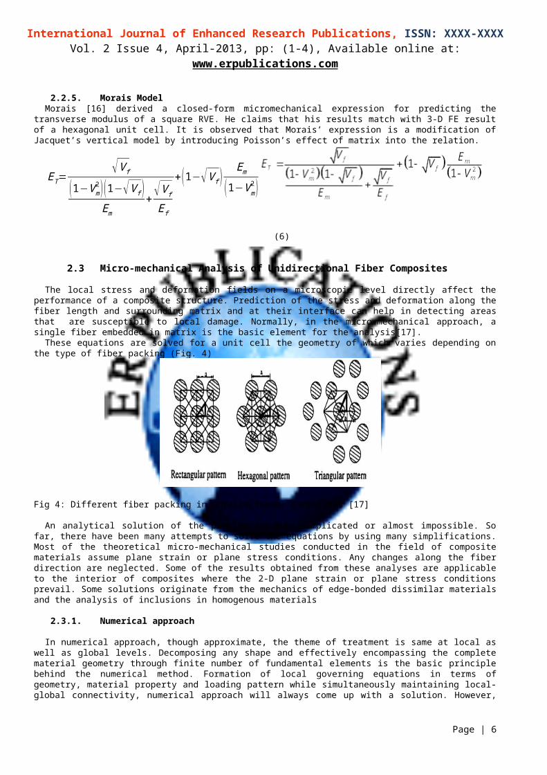
The local stress and deformation fields on a microscopic level directly affect the performance of a composite structure. Prediction of the stress and deformation along the fiber length and surrounding matrix and at their interface can help in detecting areas that are susceptible to local damage. Normally, in the micro-mechanical approach, a single fiber embedded in matrix is the basic element for the analysis[17].
These equations are solved for a unit cell the geometry of which varies depending on the type of fiber packing (Fig. 4)
Fig 4: Different fiber packing in unidirectional composites [17]
An analytical solution of the problem is very complicated or almost impossible. So far, there have been many attempts to solve the equations by using many simplifications. Most of the theoretical micro-mechanical studies conducted in the field of composite materials assume plane strain or plane stress conditions. Any changes along the fiber direction are neglected. Some of the results obtained from these analyses are applicable to the interior of composites where the 2-D plane strain or plane stress conditions prevail. Some solutions originate from the mechanics of edge-bonded dissimilar materials and the analysis of inclusions in homogenous materials
2.3.1. Numerical approach
In numerical approach, though approximate, the theme of treatment is same at local as well as global levels. Decomposing any shape and effectively encompassing the complete material geometry through finite number of fundamental elements is the basic principle behind the numerical method. Formation of local governing equations in terms of geometry, material property and loading pattern while simultaneously maintaining local-global connectivity, numerical approach will always come up with a solution. However, validation of this solution requires bench marking that forms the basis of the present work. Numerical errors are reduced by proper choice of the element and its size and the accuracy of the outcome can be checked by testing for convergence [18].
An RVE in the form of a square unit cell in cross-section is adapted for analysis and a one eighth unit cell (one-fourth in cross-section and half in longitudinal direction) is modeled by taking the advantage of symmetry. The geometry of FE model and the composite’s constituent properties are so selected to cover sufficiently a large range of fiber volume fractions (V f = 0.2 to 0.6) in order to compare FE results with available analytical results.
2.3.2. FEM Modeling
In order to reduce the cost of FEM calculations it is necessary to assume a regular pattern for the fiber distribution in the matrix. Among the different patterns the rectangular and hexagonal patterns are widely used four micro-mechanical models to analyze
Page | 5
International Journal of Enhanced Research Publications, ISSN: XXXX-XXXXVol. 2 Issue 4, April-2013, pp: (1-4), Available online at: www.erpublications.com
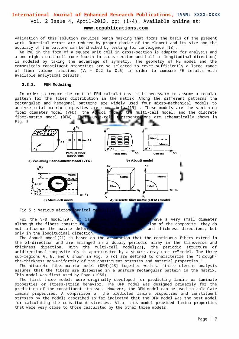
metal matrix composites are shown below[19] . These models are the vanishing fiber diameter model (VFD), the Aboudi model, the multi-cell model, and the discrete fiber-matrix model (DFM). Their unit-cell representations are schematically shown in Fig. 5
Fig 5 : Various micromechanical models[19]
For the VFD model[20], it is assumed that the fibers have a very small diameter although the fibers constitute an appreciable volume fraction of the composite, they do not influence the matrix deformation in the transverse and thickness directions, but only in the longitudinal direction.
The Aboudi model[21] is based on the assumption that the continuous fibers extend in the xl-direction and are arranged in a doubly periodic array in the transverse and thickness direction. With the multi-cell model[22], the periodic structure of unidirectional composite ply is approximated by a square array unit cell model. The three sub-regions A, B, and C shown in Fig. 5 (c) are defined to characterize the "through-the-thickness non-uniformity of the constituent stresses and material properties."
The discrete fiber-matrix model (DFM)[23] together with a finite element analysis assumes that the fibers are dispersed in a uniform rectangular pattern in the matrix. This model was first used by Foye (1966).
The first three models were originally developed for predicting lamina or laminate properties or stress-strain behavior. The DFM model was designed primarily for the prediction of the constituent stresses. However, the DFM model can be used to calculate lamina properties. A comparison of the predicted lamina properties and constituent stresses by the models described so far indicated that the DFM model was the best model for calculating the constituent stresses. Also, this model provided lamina properties that were very close to those calculated by the other three models.
2.3.3. Stress analysis through beam cross-section:
The fiber-matrix packing system is adopted for the idealization of the material of the composite beam under consideration due to its advantages, as it has more symmetry transformations, and it preserves the property of transverse isotropy, and it is characterized by its compactness compared with other packing systems. The layout has what so called the periodic element translations of which in y- and z-direction can cover the whole area of the cross section . The size of this periodic element can be reduced to quarter of it, which can also be further reduced to a unit cell size by virtue of the translational and reflectional symmetry transformations existed in the system.
3. MODELING OF BEAM FOR MICROMECHANICAL ANALYSIS
For a realistic computer simulation of a physical problem by the FEM an accurate modeling of the geometry, the material, and the loads involved is necessary. On the other hand, the FEM model must be numerically manageable and optimized in order to avoid excessive computer time and storage space requirements.
3.1. FEM Analysis of Composites
The finite element simulation was done by finite element analysis package ANSYS (14). The FEA software ANSYS includes time-tested, industrial leading applications for structural, thermal, mechanical, computational fluid dynamics and electromagnetic analysis. ANSYS software solves for the combined effects of multiple forces, accurately modeling combined behaviors resulting from “metaphysics interaction”.
The purpose of the finite element package was utilized to model the fiber reinforced polymer composite in three dimensions as SOLID. This package enables the user to investigate the physical and mechanical behavior of the beam.
Page | 6
International Journal of Enhanced Research Publications, ISSN: XXXX-XXXXVol. 2 Issue 4, April-2013, pp: (1-4), Available online at: www.erpublications.com
3.2. Model Development
The analysis deals with the evaluation of the in plane transverse Young’s modulus ET, Poison’s ratios and determination of the stresses at the fiber matrix interfaces for a complete possible range of fiber volume fractions using 3-D finite element analysis based on theory of elasticity.
In finite element model the 1-2-3 coordinate system shown in Fig. 6 is used to study the behavior of unit cell. The isolated unit cell behaves as a part of large array of unit cells by satisfying the conditions that the boundaries of the isolated unit cell remain plane.
Fig. 6 — Concept of unit cells [19]
It is assumed that the geometry, material and loading of unit cell are symmetric with respect to 1-2- 3 coordinate system. Therefore, a one-fourth portion of the unit cell is modeled for the analysis (Fig. 7).
Fig 7 : Isolated unit cell of square packed array[19]
The dimensions of the finite element model are taken as(i) X=250 units (in-plane Transverse direction),(ii) Y=250 units (out-of-plane transverse direction) (iii) Z=10 units (fiber direction).
The radius of fiber is varied corresponding to the volume fraction. For example, the radius of the fiber is calculated as 175.6 units, so that the fiber volume fraction becomes 0.40.
Fig 8: Quarter of unit cell
Due to the symmetry of the problem, the following symmetric boundary conditions are used
Page | 7

International Journal of Enhanced Research Publications, ISSN: XXXX-XXXXVol. 2 Issue 4, April-2013, pp: (1-4), Available online at: www.erpublications.com
at x = 0, Ux = 0at y = 0, Uy = 0at z = 0, Uz = 0
In addition the following multi point constraints are used.The Ux of all the nodes on the line at x =250 is sameThe Uy of all the nodes on the line at y =250 is sameThe Uz of all the nodes on the line at z = 10 is same
Fig 9 :Mesh Model of Micro Beam
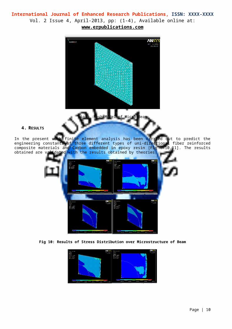
4. RESULTS
In the present work finite element analysis has been carried out to predict the engineering constants of three different types of uni-directional fiber reinforced composite materials and Carbon embedded in epoxy resin [Fig .-10,11]. The results obtained are validated with the results obtained by theories.
Fig 10: Results of Stress Distribution over Microstructure of Beam
Page | 8

International Journal of Enhanced Research Publications, ISSN: XXXX-XXXXVol. 2 Issue 4, April-2013, pp: (1-4), Available online at: www.erpublications.com
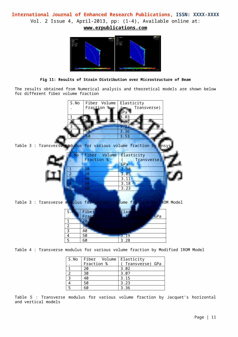
Fig 11: Results of Strain Distribution over Microstructure of Beam
The results obtained from Numerical analysis and theoretical models are shown below for different fiber volume fraction
S.No. Fiber Volume Fraction %
Elasticity ( Transverse) GPa
1 20 3.032 30 3.123 40 3.274 50 3.365 60 3.53
Table 3 : Transverse modulus for various volume fraction by Ansys
S.No. Fiber Volume Fraction %
Elasticity ( Transverse) GPa
1 20 2.982 30 3.053 40 3.114 50 3.185 60 3.23
Table 3 : Transverse modulus for various volume fraction by IROM Model
S.No. Fiber Volume Fraction %
Elasticity ( Transverse) GPa
1 20 2.952 30 3.023 40 3.114 50 3.195 60 3.28
Table 4 : Transverse modulus for various volume fraction by Modified IROM Model
S.No. Fiber Volume Fraction %
Elasticity ( Transverse) GPa
1 20 3.022 30 3.073 40 3.154 50 3.235 60 3.36
Table 5 : Transverse modulus for various volume fraction by Jacquet’s horizontal and vertical models
S.No. Fiber Volume Fraction %
Elasticity (Transverse) GPa
1 20 3.042 30 3.113 40 3.21
Page | 9
International Journal of Enhanced Research Publications, ISSN: XXXX-XXXXVol. 2 Issue 4, April-2013, pp: (1-4), Available online at: www.erpublications.com
4 50 3.335 60 3.46
Table 6 : Transverse modulus for various volume fraction by Halpin-Tsai model (H-TSAI)
S.No. Fiber Volume Fraction %
Elasticity ( Transverse) GPa
1 20 2.742 30 2.963 40 3.094 50 3.225 60 3.37
Table 7 : Transverse modulus for various volume fraction by Morais model
Fig 8 : Comparative Results observed by analytical and numerical methods
5. CONCLUSION
The analytical models predict values of ET with increasing Vf in comparison to FE model. IROM model predicts the least value for ET, while FE model predicts the highest and the rest of the models are positioned in between
It is also observed that the magnitude of ET has not been affected by the variation of 20 to 50 in analytical models as much as it has been in FE model. Rather, it could be stated that FE model responds more sensitively to variation of Ef compared to all analytical models referred here in case of transverse modulus.
It is also observed that the differences in values of ET between each of these models and FE model is progressively increasing with increasing Vf.
It is observed that Halpin-Tsai predicts higher values than all other analytical models considered so far here.Relative closeness of experimental and FE results confirms the dependability of FEM in predicting transverse modulus of
fiber reinforced compositesThis proposed work enables the authors to state that FEM can be extended in micromechanical analysis of composites to
study those cases where conventional analytical models are unable to address.The proposed modeling framework for p composites can be used as a platform to implement different matrix constitutive
behaviors, such as visco-elastic and hygrothermal models. Furthermore, large--scale analysis of structures and connections can be achieved using the current micro-models. This should help in the simulation of the structural response and enhance the design of these structures.
REFERENCES
[1] Asp, L.E, Berglund. L.A., “Effects of fiber and interface on matrix-initiated transverse failure in polymer composites.” Composites Science and Technology, vol. 56, pages 657-665. 1996,
Page | 10
International Journal of Enhanced Research Publications, ISSN: XXXX-XXXXVol. 2 Issue 4, April-2013, pp: (1-4), Available online at: www.erpublications.com
[2] Vihari.N.K., Prasanthi.P and Murthy .V,B.K. “Micromechanical Analysis of FRP Composites Subjected to Thermal Loading” International Journal of Mechanics and Solids, vol. 8, (2) pp. 199-206. 2012,
[3] Chen C. H. & Cheng S., Transaction of ASME Journal of Applied Mechanics, 37 186-189.(2010).[4] HussainS.A., Reddy.B.S., and Reddy.V,N,, “prediction of elastic properties of FRM composite lamina for Longitudinal loading” Asian Research Publishing Network
(ARPN), vol. 3(6), , pp. 70-75. (2008)[5] Wang, Q. and Chiang, F.P., “Experimental characterization of interface mechanical properties of composites.” Composites, part: B, vol. 27B, pp. 123-128. 2006,[6] Halpin-Tsai JC, Kardos JL (1976). The Halpin-Tsai equations: A review. Polymer Eng. Sci. 16(5). [7] Autar KK (1997). Mechanics of Composite Materials, CRC Press. [8] Asp, L.E, Berglund. L.A., “Effects of fiber and interface on matrix-initiated transverse failure in polymer composites.” Composites Science and Technology, vol. 56, pages
657-665. 1996,[9] Hui-Zu S, Tsu-Wei C (1995). Transverse elastic moduli of unidirectional fiber composite with fiber/matrix interfacial debonding. Compos. Sci. Technol. 53:383- [10] Alfredo BM (2000). Transverse moduli of continuous fiber reinforced polymers, Compos. Sci. Technol. 60:997-1002. [11] Halpin-Tsai JC, Kardos JL (1976). The Halpin-Tsai equations: A review. Polymer Eng. Sci. 16(5). [12] Jacquet E, Trivaudey F, Varchon D (2000). Calculation of the transverse modulus of a unidirectional composite material and of the modulus of an aggregate: Application of
rule of mixtures. Compos. Sci. Technol. 60:345-350. [13] Timoshinko, S. P. and J. N. Goodier, 1970 “Theory of Elasticity”, 3rd Ed. McGraw-Hill, New York, U.S.A.,.[14] Aghdam M.M., Smith D.J. and Pavier M.J. “Finite element micromechanical modelling of yield and collapse behaviour of metal matrix composites”. Journal of the
Mechanics and Physics of Solids, Vol. 48, pp 499-528, 2000.[15] Li,S., Zuo Z., "Unit cell And Micromechanical Finite Element Analysis Of Unidirectional Fiber-Reinforced Composites", ECCM9, Composites: From Fundamentals To
Exploitation, 4-7 June, Brighton, U.K. 2000,[16] Babu,P.E.J., Savithri S., Pillai,U.T.S. Pai,B.C., "Application Of Generalized Method Of Cells Principle To Particulate-Reinforced Metal Matrix Composites",
http://www.Google.com, Regional Research Laboratory, Kerala, India. 2004,[17] Alfredo BM (2000). Transverse moduli of continuous fiber reinforced polymers, Compos. Sci. Technol. 60:997-1002. [18] Huang, Z.M., “Simulation of the mechanical properties of fibrous composites by the bridging micromechanics model,” Composites: Part A, vol. 32, pages 143-173. 2001,[19] Anifantis, N.K., “Micromechanical stress analysis of closely packed fibrous composites”, Composites science and technology, vol. 60, pages 2281-2295. 2000,[20] Bigelow, C. A, Johnson, W. S., and Naik, R A. 'A comparison of various micromechanics models for metal matrix composites' Mechanics of Composite Materials and
Structures, Reddy. J. N. and Teply, J. L ASME, New York, p. 2 1, (1989).[21] Hashin Z., "Analysis Of Composite Material A survey", ASME., J. Appl. Mech., Vol. 50, pp. 481-505. 1983[22] Aboudi J., "Micromechanical Analysis Of Composites By The Method Of Cells", ASME., J. Appl. Mech., Rev. 42, pp. 193-221. 1989.[23] Foye, R L. 'An evaluation of various engineering estimates of the transverse properties ofunidirectional composites' Proceedings of the Tenth National SAMP E
Symposiwn-Advanced Fibrous Reinforced Composites, p. 155, (1966).[24] ANSYS Reference Manuals, 2012.[25] Robertson, D.D., and Mall, S., “Micromechanical relations for Fiber-Reinforced composites using the free transverse shear approach” Journal of Composites Technology
and Research, JCTRER, vol. 15, no: 3, fall pages 181-192. 1993,
Page | 11