papercraft panoramas - the bridges...
TRANSCRIPT
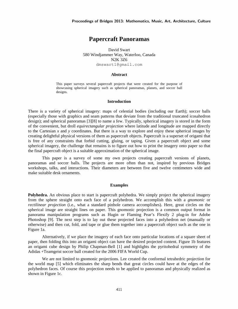
Papercraft Panoramas
David Swart
580 Windjammer Way, Waterloo, Canada N2K 3Z6
Abstract
This paper surveys several papercraft projects that were created for the purpose of showcasing spherical imagery such as spherical panoramas, planets, and soccer ball designs.
Introduction
There is a variety of spherical imagery: maps of celestial bodies (including our Earth); soccer balls (especially those with graphics and seam patterns that deviate from the traditional truncated icosahedron design); and spherical panoramas [3][8] to name a few. Typically, spherical imagery is stored in the form of the convenient, but droll equirectangular projection where latitude and longitude are mapped directly to the Cartesian x and y coordinates. But there is a way to explore and enjoy these spherical images by creating delightful physical versions of them as papercraft objects. Papercraft is a superset of origami that is free of any constraints that forbid cutting, gluing, or taping. Given a papercraft object and some spherical imagery, the challenge that remains is to figure out how to print the imagery onto paper so that the final papercraft object is a suitable approximation of the spherical image.
This paper is a survey of some my own projects creating papercraft versions of planets, panoramas and soccer balls. The projects are more often than not, inspired by previous Bridges workshops, talks, and interactions. Their diameters are between five and twelve centimeters wide and make suitable desk ornaments.
Examples Polyhedra. An obvious place to start is papercraft polyhedra. We simply project the spherical imagery from the sphere straight onto each face of a polyhedron. We accomplish this with a gnomonic or rectilinear projection (i.e., what a standard pinhole camera accomplishes). Here, great circles on the spherical image are straight lines on paper. This gnomonic projection is a common output format in panorama manipulation programs such as Hugin or Flaming Pear’s Flexify 2 plug-in for Adobe Photoshop [9]. The next step is to lay out these projected faces into a polyhedron net (manually or otherwise) and then cut, fold, and tape or glue them together into a papercraft object such as the one in Figure 1a.
Alternatively, if we place the imagery of each face onto particular locations of a square sheet of paper, then folding this into an origami object can have the desired projected content. Figure 1b features an origami cube design by Philip Chapman-Bell [1] and highlights the pyritohedral symmetry of the Adidas +Teamgeist soccer ball created for the 2006 FIFA World Cup.
We are not limited to gnomonic projections. Lee created the conformal tetrahedric projection for the world map [5] which eliminates the sharp bends that great circles could have at the edges of the polyhedron faces. Of course this projection needs to be applied to panoramas and physically realized as shown in Figure 1c.
Proceedings of Bridges 2013: Mathematics, Music, Art, Architecture, Culture
411

At Bridges 2009, I encountered a simple modular origami octahedron made from six origami
“waterbomb bases” shown in Figure 2a. We cannot project our sphere onto this figure the same way as above since each face is coincident with the center of projection. Instead, we “pop out” the faces from concave to convex resulting in an octahedron with eight cube-corners glued to each face. See Figure 2b. We project the imagery onto this polyhedron, and then pop the faces back in to get the papercraft object shown in Figure 2c. Although it is difficult to appreciate the spherical imagery from our vantage, it is interesting to know that the imagery is uninterrupted and an ant would have a continuous experience as it crawls over each edge.
Figure 2: a) The original origami octahedron; b) the polyhedron obtained by ‘popping out’ the concave sections; c) the final result after projecting the world map and popping the faces back in
Slide-togethers. An interesting class of papercraft is called slide-togethers and was described by George Hart [4]. Briefly, a slide-together is constructed by placing a rectangular piece of paper over each face of an isohedral polyhedron and then adding slots at the polyhedron’s edges to slide the rectangles together. In order to project imagery onto each of these faces, we need more versatile tools than the straightforward gnomonic projections described above.
To project spherical imagery onto a slide-together face, we first overlay the designed rectangle onto one face of a polyhedron (see Figure 3 for a diagram). To render a given pixel at location P, we need to find its 3D position. Consider the pixel location (i, j) of P as coordinates in a rectangular vector space (i.e., P = O + iU + jV). Using linear algebra to do a translation and a change of basis, we can calculate the location of P instead as P = O' + i'U' + j'V' where O' is a vertex on the polyhedron’s face, and U' and V' are vectors along the coincident edges. Using known properties of the polyhedron, we calculate (or look up) the values of O', U', and V' in 3D space and plug them into this equation to get the 3D coordinates of P and from there the appropriate pixel color from the source spherical imagery. Repeating this process for every pixel of each rectangle gives us the interior content for our slide-together puzzle.
Figure 1: a) A dodecahedron Jupiter, b) an origami soccer ball cube, c) Lee’s conformal tetrahedric
projection applied to a San Francisco panorama
× 6 =
a) b) c)
a) b) c)
Swart
412

Figure 4 shows a slide-together globe that was generated this way based on the pentagonal hexecontahedron; but also, a modified version which incorporates some folds and heart shaped panels.
Figure 3: Locating a pixel on one panel of a pentagonal
hexecontahedron slide-together
Figure 4: a) A slide-together globe; b) a modified slide-together globe with a heart motif
Globemaker. My own personal software–informally called Globemaker [7]–is a versatile way to map spheres to planes for the purpose of creating paper objects such as the wiggly version shown in Figure 5. It works by mapping the imagery in Voronoi regions around a set of line segments on the sphere (a skeleton) to a corresponding set of line segments on the plane.
The papercraft object in Figure 5 was assembled using lots of small squares of tape. Chris K. Palmer created a tapeless method of joining two pieces of paper along an edge called SlideTabs [6]. We incorporate version 1.0 of this SlideTab system by modifying the Globemaker output to “bleed” the content outwards, and then manually masking in the tab shapes, resulting in the design shown in Figure 6 that uses only one piece of tape. The panorama featured here is taken from within the Zometool construction at Bridges 2009.
Figure 5: Globemaker output and the constructed sphere, assembled with tape
Figure 6: Globemaker output augmented with Chris K. Palmer’s SlideTab system.
Now in Bridges 2011, Kelly Delp presented among other things, a papercraft version of a
rounded octahedron [2]. See Figure 7a. Notice that each set of interleaved fingers could correspond to a face of a rhombic dodecahedron. This fact helped inform the structure of the Globemaker skeleton based on this design. Figure 7b shows one of eight panels used to create the papercraft object in Figure 7c.
a) b)
Papercraft Panoramas
413
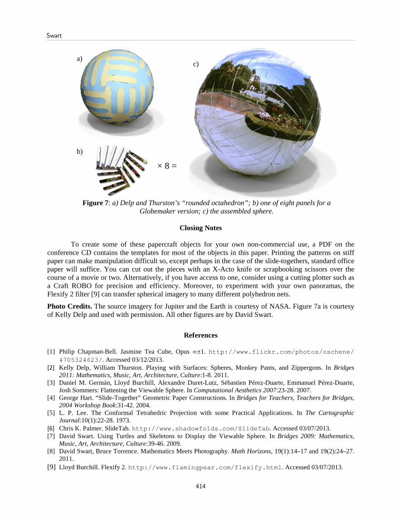
Figure 7: a) Delp and Thurston’s “rounded octahedron”; b) one of eight panels for a
Globemaker version; c) the assembled sphere.
Closing Notes
To create some of these papercraft objects for your own non-commercial use, a PDF on the conference CD contains the templates for most of the objects in this paper. Printing the patterns on stiff paper can make manipulation difficult so, except perhaps in the case of the slide-togethers, standard office paper will suffice. You can cut out the pieces with an X-Acto knife or scrapbooking scissors over the course of a movie or two. Alternatively, if you have access to one, consider using a cutting plotter such as a Craft ROBO for precision and efficiency. Moreover, to experiment with your own panoramas, the Flexify 2 filter [9] can transfer spherical imagery to many different polyhedron nets.
Photo Credits. The source imagery for Jupiter and the Earth is courtesy of NASA. Figure 7a is courtesy of Kelly Delp and used with permission. All other figures are by David Swart.
References [1] Philip Chapman-Bell. Jasmine Tea Cube, Opus ∞±1. http://www.flickr.com/photos/oschene/
4705324623/. Accessed 03/12/2013. [2] Kelly Delp, William Thurston. Playing with Surfaces: Spheres, Monkey Pants, and Zippergons. In Bridges
2011: Mathematics, Music, Art, Architecture, Culture:1-8. 2011. [3] Daniel M. Germán, Lloyd Burchill, Alexandre Duret-Lutz, Sébastien Pérez-Duarte, Emmanuel Pérez-Duarte,
Josh Sommers: Flattening the Viewable Sphere. In Computational Aesthetics 2007:23-28. 2007. [4] George Hart. “Slide-Together” Geometric Paper Constructions. In Bridges for Teachers, Teachers for Bridges,
2004 Workshop Book:31-42. 2004. [5] L. P. Lee. The Conformal Tetrahedric Projection with some Practical Applications. In The Cartographic
Journal:10(1):22-28. 1973. [6] Chris K. Palmer. SlideTab. http://www.shadowfolds.com/SlideTab. Accessed 03/07/2013.
[7] David Swart. Using Turtles and Skeletons to Display the Viewable Sphere. In Bridges 2009: Mathematics, Music, Art, Architecture, Culture:39-46. 2009.
[8] David Swart, Bruce Torrence. Mathematics Meets Photography. Math Horizons, 19(1):14–17 and 19(2):24–27. 2011.
[9] Lloyd Burchill. Flexify 2. http://www.flamingpear.com/flexify.html. Accessed 03/07/2013.
a)
b)
c)
× 8 =
Swart
414