paradox communicator module gprs edition pcs100 v1
TRANSCRIPT

Paradox Communicator ModuleGPRS EditionPCS100 V1.6
Installation and User Manual

WarrantyFor complete warranty information on this product please refer to the Limited Warranty Statement found on the website www.paradox.com/terms. Your use of the Paradox product signifies your acceptance of all warranty terms and conditions.
PatentsOne or more of the following US patents may apply: 7046142, 6215399, 6111256, 6104319, 5920259, 5886632, 5721542, 5287111, 5119069, 5077549 and RE39406. Canadian and international patents may also apply.
© 2008 Paradox Security Systems Ltd. All rights reserved. Specifications may change without prior notice. Digiplex EVO is a trademark or registered trademarks of Paradox Security Systems Ltd. or its affiliates in Canada, the United States and/or other countries.

INCLUDED ITEMS• PCS100 Communicator Module• Metal box• Antenna• Serial cable
IMPORTANT BEFORE STARTING• Requires active SIM Card (sold by your GSM network provider)
OPTIONAL ACCESSORIESAntenna Extension: An antenna extension can be used if the reception at the PCS100 installation location is not satisfactory. The use of antenna extensions greater than 7m (24ft) can cause a loss of signal quality between the antenna and the PCS100 module. Signal loss is proportionate to the length of the antenna extension. Try to locate the best antenna location while using the shortest possible extension to avoid losing signal quality. Refer to page 8 for antenna connection information. The following is a list of available antenna extensions’.EXT2: 2m(6ft) EXT15: 14.5m(48ft)EXT4: 4m(12ft) EXT18: 18m(60ft)EXT7: 7m(24ft)
12 Vdc External Power Supply: The PCS100 is designed to be powered by the control panel. However, if you want the PCS100 to function even if the control panel’s battery is low, or if power failures are anticipated, an external power supply with a backup battery (such as the PS-817, sold separately) is highly recommended. Also, the current draw increases as the signal quality diminishes. If the signal strength is weak, the PCS100 will use more power during transmission. Refer to page 6 for power supply connection information.


1
Table of Contents
Chapter 1: Product Overview.................................................................3
Technical Specifications......................................................................... 4
Chapter 2: Installation............................................................................. 5
Step 1: Preparing the Installation ............................................................5Step 2: Insert the active SIM Card ..........................................................5Step 3: Connections............................................................................... 6Step 4: Mounting the Metal Box ..............................................................8Step 5: Connect the Antenna ..................................................................8Frequency Bandwidth Selection............................................................. 9LED Status Display ...............................................................................10
Chapter 3: Configuring the PCS100 Module.......................................11
Step 1: Connecting to the GPRS Network ............................................11Step 2: Configuring WinLoad Access....................................................13Step 3: Programming and Registering the Control Panel for GPRS Re-porting ...................................................................................................14
Chapter 4: Text Message (SMS) Notification ......................................26
Text Message Language.......................................................................27End User SMS Programming................................................................28View GSM IP Information......................................................................29Cancel SMS Communications ..............................................................30
Chapter 5: Upgrading the Firmware ....................................................31
On-Site Firmware Upgrade ...................................................................31Remote Firmware Upgrade.................................................................. 32
Chapter 6: Supervision Options ..........................................................34
GSM No Service Trouble Options.........................................................34GSM RF Jamming Supervision.............................................................34Control Panel Supervision.....................................................................35

2
Chapter 7: Private Networks ................................................................36
Trouble Connecting to the PCS100 Module..........................................36
Appendix: .......................................................................... 38SMS Message Information....................................................................38Event Groups ........................................................................................38List of SMS Phone Numbers.................................................................42Entering Special Characters .................................................................44

Product Overview 3
Chapter 1Product OverviewThe PCS100 Communicator Module provides Paradox control panels with wireless communication capabilities to report system events to a monitoring station and remotely upload/download with WinLoad software via GPRS. All of this is achieved through proprietary communication via simple 4-wire serial connection between the control panel and the PCS100 module.
• Upload/Download via GPRS: The PCS100 provides fast upload/download via a GPRS connection. GPRS allows internet communications through a GSM (cell phone) network at data rates of up to 38.8 Kbit/s. Refer to Chapter 3 “Configuring the PCS100 Module” on page 11.
• GPRS Reporting: Control panels with a PCS100 module can report system events to a monitoring station via GPRS. Refer to Chapter 3 “Configuring the PCS100 Module” on page 11.
• Control panel communication supervision: The PCS100 will report to the monitoring station should there be a loss of communication with the control panel. Refer to Chapter 6 “Supervision Options” on page 34.
• GSM RF jamming detection: When detected, the control panel will generate a trouble as well as report it to the monitoring station. Refer to Chapter 6 “Supervision Options” on page 34.
• In-field upgradeable: The PCS100 is in-field firmware upgradeable. The firmware upgrade can be conducted remotely using the WinLoad software or upgraded directly on-site. Refer to Chapter 5 “Upgrading the Firmware” on page 31.
• Simple installation: The PCS100 can be installed with a simple 4-wire serial connection up to 2m (8ft) from the panel. The module antenna can be installed up to 18m (60ft) from the module using optional antenna cable extensions depending on the local signal strength. Refer to Chapter 2 “Installation” on page 5.
4 Product Overview
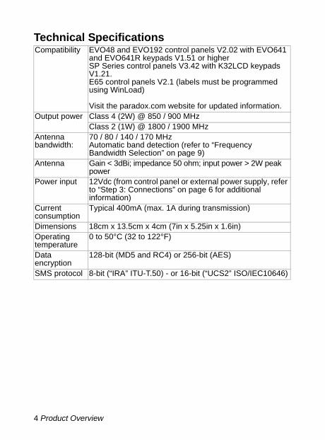
Technical SpecificationsCompatibility EVO48 and EVO192 control panels V2.02 with EVO641
and EVO641R keypads V1.51 or higherSP Series control panels V3.42 with K32LCD keypads V1.21.E65 control panels V2.1 (labels must be programmed using WinLoad)
Visit the paradox.com website for updated information.Output power Class 4 (2W) @ 850 / 900 MHz
Class 2 (1W) @ 1800 / 1900 MHz Antenna bandwidth:
70 / 80 / 140 / 170 MHz Automatic band detection (refer to “Frequency Bandwidth Selection” on page 9)
Antenna Gain < 3dBi; impedance 50 ohm; input power > 2W peak power
Power input 12Vdc (from control panel or external power supply, refer to “Step 3: Connections” on page 6 for additional information)
Current consumption
Typical 400mA (max. 1A during transmission)
Dimensions 18cm x 13.5cm x 4cm (7in x 5.25in x 1.6in) Operating temperature
0 to 50°C (32 to 122°F)
Data encryption
128-bit (MD5 and RC4) or 256-bit (AES)
SMS protocol 8-bit (“IRA” ITU-T.50) - or 16-bit (“UCS2” ISO/IEC10646)

Installation 5
Chapter 2InstallationThis chapter describes the basic hardware installation steps.
Step 1: Preparing the InstallationOpen the metal box, then remove the screws holding the PCB in place to facilitate wire connection.
Step 2: Insert the active SIM CardThe SIM card contains all information concerning your cell phone account. It is sold by GSM network provider that support GSM. To activate your SIM card, contact your GSM network provider.
Open the SIM card tray slowly to avoid damage to the tray.
Note: The International Mobile Equipment Identity (IMEI) number is located on the white sticker placed next to the antenna connection on the PCS100 board.
1. Slide the SIM card tray towards the bottom of the board to unlock it.
2. Flip the SIM card tray open then insert the SIM card in the tray with the cut-off corner at the bottom left.
3. Close the SIM card tray; the cut-off corner should be in the top left. Slide the SIM card tray up to lock it into place.
Step 1 Preparing the Installation page 5Step 2 Inserting the SIM Card page 5Step 3 Connecting the Module page 6Step 4 Mounting the Metal Box page 8Step 5 Connecting the Antenna page 8
+ -12 VDC
A+ B- RS485
J3
J2
IN-FIELDPROGRAM
SERIAL (UART)
1
2
3

6 Installation
Step 3: ConnectionsThe PCS100 is connected from the In-Field connector directly to the control panel using a serial cable, as shown in Figure 2 on page 7. The connection to the PCS100 GPRS editor is different from the connection used with the GSM edition.
External Power SupplyThe PCS100 is designed to be powered by the control panel via the serial cable. However, if you want the PCS100 to function even if the control panel’s battery is low, or if power failures are anticipated, an external power supply with a backup battery (such as the PS817) is highly recommended. The optional external power supply connection is also explained in the connection diagram on page 7.
Note: The current draw increases as the signal quality diminishes; if the signal strength is weak, the PCS100 will use more power during transmission.
Connection with External Power SupplyIf your PCS100 is powered by an external power supply such as the PS817, the serial cable’s wires need to be modified prior to connection onto the PCS100 Module and the control panel. This modification is necessary to maintain proper voltage readings on the control panel.Serial Cable Modifications1. Ensure that one end of the serial cable’s white wire is cut prior to
connecting it to the PCS100’s In-Field Program connector.2. Connect the other end directly to the control panel’s Serial
connector.Figure 1: Serial Cable Modifications
WhiteGreenRedBlack
WhiteGreen
RedBlack
Cut White Wire

Installation 7
Figure 2: GPRS Serial Connection
+ -12 VDC
A+ B- RS485
J3
J2
IN-FIELDPROGRAM
AC AC + - TSTSERIAL (UART)
SERI
AL
Transformer
Control Panel
SIM CardRefer to “Step 2: Insert the active SIM Card” on page 5 for instructions on how to insert the SIM Card.
PS817OptionalPowerSupply
Serial ConnectionConnect the Serial Cable to the PCS100’sIn-Field Programmer connector and to thecontrol panel’s serial connector.
PCS100
Up to 2 m
Ensure that the whitewire is cut when usingan external power supply.
NOTE: The connection for the PCS100 GPRS edition is different from the connection used with the GSM edition.

8 Installation
Step 4: Mounting the Metal BoxMount the metal box as far away as possible from any electronic equipment and as high as possible to ensure protection from interference and to maximize the signal quality.
Step 5: Connect the AntennaThe antenna connects to the antenna cable connector located on the PCS100’s PCB. The antenna cable’s connector is outside of the metal box.
Antenna Extension (Optional)Antenna extensions are available to improve reception by moving the antenna. Refer to “Optional Materials” on the inside cover for the list of extensions. The antenna extension is sold with a wall mounting bracket. Insert the antenna extension in the bracket until it snaps in and mount the bracket to the wall using the two screw holes.
J3
J2
IN-FIELDPROGRAM
The antenna cable connector is outside the metal box
Screw Holes
Mounting Bracket

Installation 9
Frequency Bandwidth SelectionThe PCS100 automatically detects the bandwidth that must be used for GSM communications. If you wish to manually select the bandwidth:1. Press and hold the bandwidth selection switch for 10 seconds. The
Module Online LED will flash rapidly. 2. The Signal Strength and GPRS LEDs will light up to indicate the
bandwidth.
3. Press the bandwidth selection switch to change between automatic band detection and specific bandwidths.
4. Press and hold the bandwidth selection switch for at least 5 seconds until the module reboots (the selections will be saved and all 4 LEDs will turn off during the reboot process). If the bandwidth selection switch is not pressed for more than 5 seconds, the module will exit bandwidth selection mode without saving any changes.
J3
J2
IN-FIELDPROGRAM
Bandwidth Selection Switch
Signal Strength and GPRS LEDs.All on: Automatic Bandwidth DetectionGSM 850 MHz, PCS 1900 MHzGSM 850 MHz, DCS 1800 MHzGSM 900 MHz, PCS 1900 MHzGSM 900 MHz, DCS 1800 MHz
Module Online LED

10 Installation
LED Status Display
1 GSM Connection (Green)Flashes once every 3 seconds: Connected to GSM networkFlashes every second: Not connected to GSM network
2 Signal Strength Indicators (Green)These LEDs indicate the quality of the GSM Signal. 1 LED lit indicates a weak signal, 3 LEDs indicate a strong signal.
3 GPRS Connection Status (Green)On: Communication enabledFlashes: Communication in progress
4 Module Online LED (Green)Flash once every second = Normal operationSlow Flash:With GSM Connection LED flashing = No SIM card insertedWith GSM Connection LED off = On-board GSM power supply failure
5 Status LEDsError (Red): Lights up to indicate problems with the communications with the control panelRX (Green): Flashes when receiving information from the panelTX (Green): Flashes when transmitting information to the panel
6 RF Jamming (Red)On: Indicates jamming of the GSM network communications
+ -12 VDC
A+ B- RS485
J3
J2
IN-FIELDPROGRAM
SERIAL (UART)
1: GSMConnection
2: SignalStrength
3: GPRSConnection
4: ModuleOnline
5: Status
6: RFJamming

Configuring the PCS100 Module 11
Chapter 3Configuring the PCS100 ModuleThe following sections describe how to configure the PCS100 module for WinLoad access via GPRS, GPRS reporting, and how to program and register the control panel to the monitoring station.
This chapter describes the configuration steps for the PCS100 module.
Step 1: Connecting to the GPRS Network To connect the PCS100 Module to the GPRS network, certain registration parameters must be set (supplied by your GSM network provider). These parameters include:
• Access Point Name (APN)• APN User Name• APN Password
Note: The Access Point Name, APN User Name and APN password are determined by your GSM network provider; contact them to get that information.
GSM Network Provider InformationTo begin the configuration of your GSM network provider information, enter the section required for your control panel, as detailed below.
Note: When entering into GSM network provider information sections, the LCD screen of the control panel’s keypad will display “Messages”.
Step 1 Connecting to the GPRS Network page 11Step 2 Configuring WinLoad Access page 13Step 3 Programming and Registering the
Control Panel for GPRS Reportingpage 14
Introduction page 14EVO Sections page 14 to page 20SP/E65 Sections page 20 to page 25

12 Configuring the PCS100 Module
Access Point Name (APN)This information can be obtained from your GSM network provider. For APNs over 16 characters, use the second section to enter characters 17 to 32.Default: Blank
APN Part 1 (Characters 1 to 16) Digiplex EVO Section [2960]SP Series / E65 Section [921] _ / _ / _ / _ / _ / _ / _ / _ / _ / _ / _ / _ / _ / _ / _ / _ /Note: Use the numeric keys on the control panel’s keypad to enter letters. APN Part 2 (Characters 17 to 32)Digiplex EVO Section [2961]SP Series E65 Section [922] _ / _ / _ / _ / _ / _ / _ / _ / _ / _ / _ / _ / _ / _ / _ / _ /Example: wap.provider.com
Note: Refer to “Entering Special Characters” on page 44 for information on how to enter characters and special characters. It is possible to program the PCS100 with any compatible keypad, refer to “Technical Specifications” on page 4 for more information. To enter text without a K32LCD when programming with an SP Series or E65, use WinLoad.
APN User NameThis information can be obtained from your GSM network provider. For user names over 16 characters, use the second section to enter characters 17 to 32.Default: Blank
User Name Part 1 (Characters 1 to 16)Digiplex EVO Section [2962] SP Series / E65 Section [923] _ / _ / _ / _ / _ / _ / _ / _ / _ / _ / _ / _ / _ / _ / _ / _ /
User Name Part 2 (Characters 17 to 32)Digiplex EVO Section [2963] SP Series / E65 Section [924]_ / _ / _ / _ / _ / _ / _ / _ / _ / _ / _ / _ / _ / _ / _ / _ /
Example: userAPN PasswordThis information can be obtained from your GSM network provider. For passwords over 16 characters, use the second section to enter characters 17 to 32.Default: Blank

Configuring the PCS100 Module 13
Password Part 1 (Characters 1 to 16)Digiplex EVO Section [2964] SP Series / E65 Section [925]_ / _ / _ / _ / _ / _ / _ / _ / _ / _ / _ / _ / _ / _ / _ / _ /
Password Part 2 (Characters 17 to 32)Digiplex EVO Section [2965] SP Series / E65 Section [926]_ / _ / _ / _ / _ / _ / _ / _ / _ / _ / _ / _ / _ / _ / _ / _ /Example: password
Step 2: Configuring WinLoad AccessThe PCS100 provides remote access for upload and download withWinLoad via a GPRS connection at data rates of up to 38.8 Kbit/s. Thefollowing site specific information must be configured for WinLoadaccess.Site Specific InformationThe following information is determined by the installer and is specific to the installation site.Software PortThe Software Port must match the port entered in the WinLoad or NEware software’s GPRS Connection Settings for that site’s account. This is the port that the module will listen on for incoming GPRS communication.
Default: 10000
Port Digiplex EVO Section [2966] SP Series / E65 Section [920]_ / _ / _ / _ / _ Installer Software PasswordThe Installer Software Password is used to access installer software through TCP/IP and GPRS networks. The password is case sensitive. This password is entered in WinLoad’s GPRS Connection Settings for that site’s account.
Default: admin
WinLoad TCP/IP/GPRS Password (default “admin”)Digiplex EVO Section [3013] SP Series / E65 Section [927] _ / _ / _ / _ / _ / _ / _ / _ / _ / _ / _ / _ / _ / _ / _ / _ /

14 Configuring the PCS100 Module
Step 3: Programming and Registering the Control Panel for GPRS ReportingControl panels with a PCS100 module can report system events to a monitoring station over an IP network. The process of setting up reporting through a PCS100 is similar to that of standard telephone reporting, however the PCS100 module must first be registered with IP receivers located at the monitoring station.Before registering the PCS100, the following information must be obtained from the monitoring station:
• Account number(s) - One account number for each partition used. IP/GPRS reporting uses a different set of account numbers than those used for dialer reporting. The specific section numbers for the IP/GPRS Account Numbers are listed in this document.
• IP address(es) - The IP address(es) indicates which of the monitoring station’s IP receivers will be used for IP reporting. The IP address is a 12-digit number for e.g. 195.4.8.250 must be entered as 195.004.008.250.
• IP port(s) - The IP port refers to the port used by the monitoring station’s IP Receiver. The IP port is a 5-digit number. For 4-digit numbers, enter 0 before the first digit.
• Receiver password(s) - The receiver password is used to encrypt the PCS100 registration process. The Receiver password can be up to 32-digits.
• Security profile(s) - The security profile indicates how frequently the monitoring station is polled by the PCS100. Security profile numbers and polling frequency are defined by the monitoring station. The security profile is a 2-digit number.
DIGIPLEX EVOThis section provides you with the minimum requirements to set up GPRS reporting with your PCS100 module.
Setting up a PCS100 Module and Registering with a Monitoring Station1. Ensure that the panel’s report code format is set to either Ademco
Contact ID (default) or SIA (refer to section [3070] in the control panel’s programming guide). The settings, event call direction, and reporting formats will be shared by the telephone reporting and IP reporting. Telephone number 1 will share settings with IP Receiver

Configuring the PCS100 Module 15
1, telephone number 2 with IP receiver 2, telephone number 3 with IP receiver 3 and telephone number 4 with IP receiver 4.
2. If the PCS100 module is not already connected, connect the PCS100 as described in “Step 3: Connections” on page 6.
3. Enter the account numbers (one for each partition). The account numbers are used to register the PCS100 to the IPR512 Receiver.
Note: To enter letters A-F, use the function keys on the control panel’skeypad. For more information, refer to the control panel’s programming guide.
4. Ensure IP reporting is enabled in section [2975], option [8]:
Section Data Description[2976] ___/___/___/___ IP/GPRS Reporting Partition 1 /
Account 1 number[2977] ___/___/___/___ IP/GPRS Reporting Partition 2 /
Account 2 number[2978] ___/___/___/___ IP/GPRS Reporting Partition 3 /
Account 3 number[2979] ___/___/___/___ IP/GPRS Reporting Partition 4 /
Account 4 number[2980] ___/___/___/___ IP/GPRS Reporting Partition 5 /
Account 5 number[2981] ___/___/___/___ IP/GPRS Reporting Partition 6 /
Account 6 number[2982] ___/___/___/___ IP/GPRS Reporting Partition 7 /
Account 7 number[2983] ___/___/___/___ IP/GPRS Reporting Partition 8 /
Account 8 number
[2975] OFF ON
[7] Use dialer reporting (telephone)
As backup for IP/GPRS reporting
In addition to IP/GPRS reporting
[8] IP/GPRS reporting Disabled Enabled

16 Configuring the PCS100 Module
5. Enter the monitoring station’s IP address(es), IP port(s), receiver password(s), and security profile(s):Use the up and down arrow to navigate in the displays. The data is saved every time a new page is accessed.
.
Receiver 1
[2984] __/__/__. __/__/__. __/__/__. __/__/__ WAN1 IP address
__/__/__/__/__WAN1 IP port (default: 10000)
NOTE: For 1- or 2-digit numbers, add “0”s before the digit(s) e.g. 138.002.043.006
__/__/__. __/__/__. __/__/__. __/__/__ WAN2 IP address
__/__/__/__/__WAN2 IP port (default: 10000)
__/__/__/__/__/__/__/__/__/__/__/__/__/__/__/__/__/__ Receiver password NOTE: [MEM] = blank space
__/__Security profile
Note: The IPR512 Monitoring Receiver provides two ethernet ports for Internet Service Provider (ISP) redundancy. If you wish to use this feature, configure the WAN ports through two different Internet Service Providers. For more information on how to configure the WAN Ports, refer to the “IPR512 Monitoring Receiver” document.

Configuring the PCS100 Module 17
Receiver 2
[2986] __/__/__. __/__/__. __/__/__. __/__/__ WAN1 IP address
__/__/__/__/__ WAN1 IP port (default: 10000)
__/__/__. __/__/__. __/__/__. __/__/__ WAN2 IP address
__/__/__/__/__ WAN2 IP port (default: 10000)
__/__/__/__/__/__/__/__/__/__/__/__/__/__/__/__/__/__ Receiver password __/__ Security profile
Receiver 3
[2988] __/__/__. __/__/__. __/__/__. __/__/__ WAN1 IP address
__/__/__/__/__ IP port (default: 10000)
__/__/__. __/__/__. __/__/__. __/__/__ WAN2 IP address
__/__/__/__/__ WAN2 IP port (default: 10000)
__/__/__/__/__/__/__/__/__/__/__/__/__/__/__/__/__/__ Receiver password __/__ Security profile

18 Configuring the PCS100 Module
6. Register the PCS100 module with the monitoring station.The following sections also displays IP Receiver registration status and any registration errors. If a registration error occurs, use the arrows keys and scroll to see the type of trouble.
.
Once the module has been successfully registered, the keypad’s LCD screen will display the message “Registered”. To ensure that GPRS has been set up, verify the GPRS connection status LED. For more information, refer to “LED Status Display” on page 10.
Receiver 4
[2990] __/__/__. __/__/__. __/__/__. __/__/__ WAN1 IP address
__/__/__/__/__ WAN1 IP port (default: 10000)
__/__/__. __/__/__. __/__/__. __/__/__ WAN2 IP address
__/__/__/__/__ WAN2 IP port (default: 10000)
__/__/__/__/__/__/__/__/__/__/__/__/__/__/__/__/__/__ Receiver password __/__ Security profile
Receiver 1[2985] To register IP/GPRS Module, press [ARM].
Receiver 2[2987] To register IP/GPRS Module, press [ARM].
Receiver 3[2989] To register IP/GPRS Module, press [ARM].
Receiver 4[2991] To register IP/GPRS Module, press [ARM].

Configuring the PCS100 Module 19
The following sections and options have been added to support the IP Receiver (IPR512):
• New IP Troubles
• New GPRS PGM Events
Trouble Group Trouble[9] [5] Fail to communicate with IP receiver 1
[6] Fail to communicate with IP receiver 2[7] Fail to communicate with IP receiver 3[8] Fail to communicate with IP receiver 4[9] IP Receiver Unregistered
Event Group Event Feature
Group Feature Start End
004 Non-reportable Event
000 IPR512 1 Registration Status
021 021
IPR512 2 Registration Status
022 022
IPR512 3 Registration Status
023 023
IPR512 4 Registration Status
024 024
038 Module Trouble
001 Fail to Com. IPR512 1 004 004Fail to Com. IPR512 2 005 005Fail to Com. IPR512 3 006 006Fail to Com. IPR512 4 007 007
039 Module Trouble Restore
001 Fail to Com. IPR512 1 004 004Fail to Com. IPR512 2 005 005Fail to Com. IPR512 3 006 006Fail to Com. IPR512 4 007 007
20 Configuring the PCS100 Module
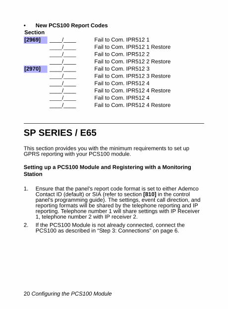
• New PCS100 Report Codes
SP SERIES / E65This section provides you with the minimum requirements to set up GPRS reporting with your PCS100 module.
Setting up a PCS100 Module and Registering with a Monitoring Station
1. Ensure that the panel’s report code format is set to either Ademco Contact ID (default) or SIA (refer to section [810] in the control panel’s programming guide). The settings, event call direction, and reporting formats will be shared by the telephone reporting and IP reporting. Telephone number 1 will share settings with IP Receiver 1, telephone number 2 with IP receiver 2.
2. If the PCS100 Module is not already connected, connect the PCS100 as described in “Step 3: Connections” on page 6.
Section[2969] ____/____ Fail to Com. IPR512 1
____/____ Fail to Com. IPR512 1 Restore ____/____ Fail to Com. IPR512 2 ____/____ Fail to Com. IPR512 2 Restore
[2970] ____/____ Fail to Com. IPR512 3 ____/____ Fail to Com. IPR512 3 Restore ____/____ Fail to Com. IPR512 4 ____/____ Fail to Com. IPR512 4 Restore ____/____ Fail to Com. IPR512 4 ____/____ Fail to Com. IPR512 4 Restore

Configuring the PCS100 Module 21
3. Enter the account numbers (one for each partition). The account numbers are used to register the PCS100 to the IPR512 Receiver.
Note: To enter letters A-F, use the function keys on the control panel’s keypad. For more information, refer to the control panel’s programming guide..
4. Ensure IP reporting is enabled in section [806] option [8]:
5. Enter the monitoring station’s IP address(es), IP port(s), receiver password(s), and security profile(s):Use the up and down arrow to navigate in the displays. The data is saved every time a new page is accessed.
Section Data Description[918] ___/___/___/___ GPRS Reporting Partition 1 / Account
1 number[919] ___/___/___/___ GPRS Reporting Partition 2 / Account
2 number
[806] OFF ON
[7] Use dialer reporting (telephone)
As backup for IP reporting
In addition to IP reporting
[8] IP reporting Disabled Enabled
Receiver 1
[929] __/__/__. __/__/__. __/__/__. __/__/__ IP addressNOTE: For 1- or 2-digit numbers, add “0”s before the
digit(s) e.g. 138.002.043.006
[930] __/__/__/__/__IP port (default: 10000)
[933] __/__/__/__/__/__/__/__/__/__/__/__/__/__/__/__/__/__ Receiver password
NOTE: [MEM] = blank space

22 Configuring the PCS100 Module
[934] __/__Security profile
Receiver 2
[936] __/__/__. __/__/__. __/__/__. __/__/__ IP address
[937] __/__/__/__/__IP port (default: 10000)
[940] __/__/__/__/__/__/__/__/__/__/__/__/__/__/__/__/__/__ Receiver password
[941] __/__Security profile
Receiver 3
[943] __/__/__. __/__/__. __/__/__. __/__/__ IP address
[944] __/__/__/__/__IP port (default: 10000)
[947] __/__/__/__/__/__/__/__/__/__/__/__/__/__/__/__/__/__ Receiver password
[948] __/__Security profile
Configuring the PCS100 Module 23
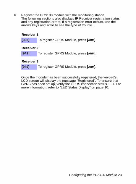
6. Register the PCS100 module with the monitoring station.The following sections also displays IP Receiver registration status and any registration errors. If a registration error occurs, use the arrows keys and scroll to see the type of trouble.
Once the module has been successfully registered, the keypad’s LCD screen will display the message “Registered”. To ensure that GPRS has been set up, verify the GPRS connection status LED. For more information, refer to “LED Status Display” on page 10.
Receiver 1[935] To register GPRS Module, press [ARM].
Receiver 2[942] To register GPRS Module, press [ARM].
Receiver 3[949] To register GPRS Module, press [ARM].

24 Configuring the PCS100 Module
The following sections and options been added to support the IP Receiver (IPR512):
• New IP Troubles
• New IP PGM Events
Trouble Group Trouble[4] Communication Trouble
[7] Fail to communicate with IP Receiver 1 or 2 (GPRS)[9] GSM Network Failure[STAY] GSM RF Interference[OFF] IP Receiver Unregistered (IP/GPRS)
Trouble Group Trouble[10] Module supervision loss
[9] GSM Module
Event Group Event Feature
Group Feature
44 Non-reportable EventNewTrouble
26 GPRS Registration Status
NewTrouble
16 Failure to communicate with IP Receiver 1 (GPRS)
New Trouble
17 Failure to communicate with IP Receiver 2 (GPRS)
45 Trouble Restore
16 Failure to communicate restore with IP Receiver 1 (GPRS)
17 Failure to communicate restore with IP Receiver 2 (GPRS)
Configuring the PCS100 Module 25
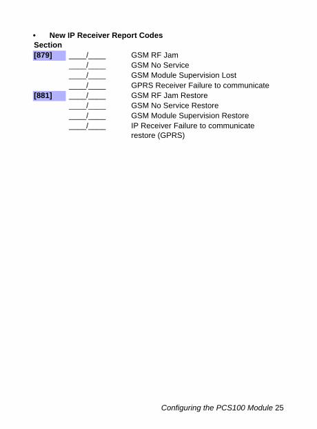
• New IP Receiver Report CodesSection[879] ____/____ GSM RF Jam
____/____ GSM No Service ____/____ GSM Module Supervision Lost ____/____ GPRS Receiver Failure to communicate
[881] ____/____ GSM RF Jam Restore ____/____ GSM No Service Restore ____/____ GSM Module Supervision Restore ____/____ IP Receiver Failure to communicate
restore (GPRS)

26 Text Message (SMS) Notification
Chapter 4Text Message (SMS) NotificationIn addition to reporting control panel events via a GSM cell phone network through GPRS, the PCS100 can also send text messages (SMS) to the end user on up to 16 cell phones. The PCS100 can send text messages for any control panel event due to its proprietary communication through the panel’s serial port. Each text message contains a detailed description of the event including site name, date and time, and any associated labels, such as area, zone and serial number. The detailed description of each system event is pre-programmed and hardcoded into the PCS100 module.
Installer Programming:• Select SMS Language• Enter Site Name
Master (End-User) Programming:• Set up to 16 cell phone
numbers • Assign areas per phone number• Select event group per phone
number• View GSM IP information

Text Message (SMS) Notification 27
Text Message LanguageSelect the language that will be used by the PCS100 when reporting system events via text message (SMS).
SMS LanguageDigiplex EVO Section [2953]SP Series / E65 Section [856]_ / _ / _ (000 - 255)
Some languages are not currently supported. If an unsupported language is selected messages will be sent in English. Some languages, like Hungarian or Romanian, will generate 2 SMS messages per event reported and other languages will use special LCD characters not supported on all cell phones. Refer to the paradox.com website for the list of languages that are supported, that generate 2 SMS messages or that use special characters.
Site NameThe site name will be included in every SMS notifications to indicate at what site the event was generated. (e.g., Paradox Headquarters).
Note: Refer to page 38 for information on how to enter characters and special characters. It is possible to program the PCS100 with any compatible keypad. To enter text without a K32LCD when programming with an SP Series, / E65 use WinLoad.
SMS Site NameDigiplex EVO Section [2954]SP Series / E65[780]_ / _ / _ / _ / _ / _ / _ / _ / _ / _ / _ / _ / _ / _ / _ / _ /Default: “Your Alarm Site”
Table 1: SMS Language
Language Value Language Value Language ValueEnglish* 000 Turkish 008 Bulgarian 016French 001 Hungarian 009 Romanian 017Spanish 002 Czech 010 Slovak 018Italian 003 Dutch 011 Chinese 019Swedish 004 Croatian 012 Serbian 020Polish 005 Greek 013 * Default valuePortuguese 006 Hebrew 014German 007 Russian 015

28 Text Message (SMS) Notification
End User SMS ProgrammingWith Master Programming, you can:• Set which phone numbers (up to 8 with SP Series / E65 or 16 with
Digiplex EVO) will receive text messages sent by the PCS100 to report system events.
• Select from which area the PCS100 will send text messages (per phone number).
• Select which event groups (alarm, arm/disarm, trouble and trouble restore) will generate text messages.
End User SMS Programming with Digiplex EVO1. To access Master Programming, enter the control panel [MASTER
CODE] then press [0].2. Press [1] to enter the SMS settings menu.3. Select which phone number you wish to program ([01] to [16]). 4. Enter or modify the phone number (up to 32 characters). To go to
the next screen press [ENTER].5. Select which partitions are enabled for that SMS number by
enabling options [1] to [8]. Press [ENTER] to go to the next screen.6. To select which events generate a SMS message, enable or disable
options [1] to [4]. (see Table 2 on page 29)7. To save press [ENTER].After saving or in the main SMS settings menu press [ ] to see which SMS numbers ([01] to [16]) are programmed. To program the SMS number currently displayed, press [ACC].End User SMS Programming with SP Series / E651. To access Master Programming, press the [ ] key.2. Enter [MASTER CODE].3. To enter SMS Setup, press [ARM]. 4. Using the [ ] and [ ]* or [STAY] keys, select one of the eight
telephone number you wish to program and press [ENTER].*With K10LEDV/H or K636 keypads, use [SLEEP] for [ ] and [STAY] for [ ].
5. Enter the telephone number and press [ENTER].6. Select the SMS Event Call Options (see Table 2 on page 29) you
wish to apply to the telephone number7. To save press [ENTER].8. Select which areas are assigned to this telephone number.9. To save press [ENTER].

Text Message (SMS) Notification 29
View GSM IP InformationIt is possible to view the following GSM IP information in Master Programming:• IP Address: Access this to determine what IP address to enter in
WinLoad or NEware’s GPRS connection settings. The IP address is determined automatically when the PCS100 connects to the GSM network. In order to properly read the IP address assigned, the GPRS LED must be on.
• IP Port: Access this to determine what IP port to enter in WinLoad or NEware’s GPRS connection settings. This is the port that the module will listen on for incoming GPRS communication. This port is programmed in section [2966] with Digiplex EVO or [920] with SP Series / E65.
• User PC Software Password: This password is needed to connect to the control panel using the NEware software. This password is determined in the NEware software.
View GSM IP Information With Digiplex EVO1. To access Master Programming, enter the [MASTER CODE] then press
[0].2. In Master Programming, press [2] to display the PCS100’s IP
information.3. The first screen displays the PCS100’s IP Address, press [ ] to
access the next screen. 4. The second screen displays the PCS100’s IP Port. Press [ ] to
access the third screen. 5. The third screen displays the PCS100 User PC Software Password.
If you press [ ] again, the Exit Message will be displayed.
Table 2: Event Call Options
Option Events that send SMS[1] Any Alarm (See Table 4 on page 38)[2] Arming and Disarming (See Table 5 on page 39)[3] Any Trouble (See Table 6 on page 40)[4] Any Trouble Restore (See Table 7 on page 41)[5] to [8] Future Use

30 Text Message (SMS) Notification
Viewing GSM IP Information With Magellan Spectra SP and E65 Control PanelsTo view IP Address, IP Port, and Site Name settings:1. Press the [ ] key.2. Enter [MASTER CODE].3. To enter SMS Setup, press [ARM].4. Using the [ ] key, scroll up to [9] GSM IP Address and press
[ENTER]. To return to the GSM menu, press [ENTER].5. Using the [ ] key, scroll up to [10] GSM IP Port and press [ENTER].
To return to the GSM menu, press [ENTER].6. Using the [ ] key, scroll up to [11] GSM PC Password (Future use).
To return to the GSM menu, press [ENTER].7. Using the [ ] key, scroll up to [12] Site Name. To return to the GSM
menu, press [ENTER].8. To exit the GSM menu, press [CLEAR].
Cancel SMS CommunicationsCancel SMS Communication With Digiplex EVOTo cancel all text messages notifications waiting to be sent, press [DISARM] on the keypad in Installer or Master programming.Cancel SMS Communication with SP Series / E65To cancel all text messages notifications waiting to be sent, use the Installer Quick MenuStep Action Details
1 + [INSTALLER CODE] = flash. [MAINTENANCE CODE] may also be used.
2
3 [9] Cancels all communication with WinLoad / GSM module.

Upgrading the Firmware 31
Chapter 5Upgrading the FirmwareThe PCS100 Module’s firmware can be upgraded using the WinLoad software application. Firmware can be upgraded either on-site, where a physical connection is required to the PCS100 module or remotely via the GPRS network.
On-Site Firmware UpgradeTo upgrade the firmware of the PCS100 module, connect a 307USB to the In-Field Program connector and to a PC with WinLoad. Start WinLoad and click on the “In-Field Firmware Programmer” button. Select the type of connection, select the product and the firmware then press “Start Transfer”. For detailed firmware upgrade instructions, visit paradox.com (paradox.com > Software > Winload > Firmware Upgrade Instructions).
Note: Ensure that the module is powered either by the panel or by the external power supply.
+ -12 VDC
A+ B- RS485
J3
J2
IN-FIELDPROGRAM
SERIAL (UART)
PC Link (USB)
RX/TX
Product Link
To PC with WinLoad V4.22 or higher

32 Upgrading the Firmware
Remote Firmware UpgradeThe firmware of the PCS100 module can be upgraded remotely using the WinLoad software application via the GPRS network.
To upgrade the firmware of the PCS100 module remotely1. Start WinLoad.2. Enter your Login Name and Password.3. Click on the In-Field Firmware Programmer button. 4. Select the type of connection.5. Select the product and the firmware then press Start Transfer.
For detailed firmware upgrade instructions, go to www.paradox.com.(paradox.com > Software > WinLoad > Firmware Upgrade Instructions)
Note: If you receive an error message, refer to “Trouble Connecting to the PCS100 Module” on page 36 for information on how to upgrade firmware on a PCS100 module that uses a private IP address.

Upgrading the Firmware 33
IP InformationIn order for WinLoad to establish a connection with the PCS100 module that you wish to upgrade, you must first know the module’s IP address.
To receive the IP address of the PCS100 Module via Text Message
1. Using a cellular phone, enter the SMS text message using the below format.
P[TCP/IP password].IP.[phone number to answer back]
Example: Padmin.IP.5551231234
2. Wait until the PCS100 sends a response to the specified phone number displaying the IP address of the PCS100 Module.
3. Enter this information in the WinLoad application. The IP address can then be used to configure remote software access. For more information, refer to “Configuring the PCS100 Module” on page 11.

34 Supervision Options
Chapter 6Supervision OptionsThe PCS100 provides several supervision and protection options to ensure you or your monitoring station is notified of problems such as RF jamming, loss of GSM service or loss of communication with the control panel.
GSM No Service Trouble OptionsThe PCS100 module verifies the presence of the GSM cell phone network approximately every 20 seconds. If it is lost, the panel can generate an alarm or trouble after the delay has elapsed (programmed in section [2952] or [855]). When the GSM Network connection is lost, the green GSM Connection LED will flash every second.
GSM No Service TimerThe delay before a GSM No Service trouble is reported.Digiplex EVO Section [2952] SP Series / E65 Section [855]_ / _ / _ (000 - 255 x 2 seconds)Default: 016 (32 seconds)
GSM RF Jamming SupervisionThis option determines if the control panel generates a trouble when RF Jamming on the GSM network is detected. This trouble can then be reported to the monitoring station. When RF Jamming is detected, the red RF Jamming LED will light up.Digiplex EVO Section [2950] Option [8]SP Series / E65 Section [805] Option [8]ON: RF Jamming Supervision enabled (Default)OFF: RF Jamming Supervision disabled
Table 3: GSM No Service Trouble Feedback
Digiplex EVO Section [2950]; options [5] & [6]SP Series / E65 Section [805]; options [5] & [6]
[5] [6]OFF OFF Disabled OFF ON When armed: Generates a trouble (default)ON OFF When armed: Generates an audible alarmON ON Silent alarm becomes and audible alarm

Supervision Options 35
Control Panel SupervisionUnique to Paradox, the PCS100 can supervise the presence of the control panel. If the communication with the control panel is lost, the PCS100 will send the report code programmed in section [2951] or [884]. When communication with the control panel is lost, the red Error LED will light up.
Reports are sent to Monitoring Station / Pager Telephone #1 using Account Number 1Digiplex EVO Section [2951]SP Series / E65 Section [884]_ / _ Panel Supervision Lost (GSM) _/ _ N/U_/ _ N/U_/ _ N/U
Default: FF
When this section is programmed with FF, the following report codes are sent:With ContactID, the code is 551 (Dialer Disabled) with a 099 ID.With SIA, the code is “IA” (Equipment failure condition) with a 099 ID.
36 Private Networks
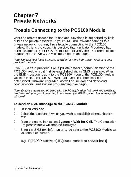
Chapter 7Private NetworksTrouble Connecting to the PCS100 ModuleWinLoad remote access for upload and download is supported by both public and private networks. If your SIM Card Provider belongs to a private network, you may have trouble connecting to the PCS100 module. If this is the case, it is possible that a private IP address has been assigned to your PCS100 module. To verify the IP address of your module, refer to “View GSM IP Information” on page 29.
Note: Contact your local SIM card provider for more information regarding your provider’s network.
If your SIM card provider is on a private network, communication to the PCS100 module must first be established via an SMS message. When the SMS message is sent to the PCS100 module, the PCS100 module will then initiate contact with WinLoad. Once communication is established, firmware upgrades, as well as, upload and download configurations, and system programming can begin.
Note: Ensure that the router, used with the PC application (Winload and NeWare), has been setup for port forwarding to ensure proper IP100 system functionality with WinLoad.
To send an SMS message to the PCS100 Module1. Launch Winload.2. Select the account in which you wish to establish communication
with.3. From the menu bar, select System > Wait for Call. The Connection
Progress window will then be displayed.4. Enter the SMS text information to be sent to the PCS100 Module as
you see it on screen.
e.g., P[TCP/IP password].IP.[phone number to answer back]

Private Networks 37
The Connection Progress window will then be displayed on your screen displaying the SMS text information to be sent to the PCS100 module.
Figure 3: Connection Progress
To upgrade the firmware using the In-Field Firmware Programmer, refer to “Upgrading the Firmware” on page 31.
SMS

38 Appendix
Appendix
SMS Message Information
Event GroupsThe following tables list all pre-defined text messages that can be sent (see Chapter 4 on page 26). These messages follow the 8-bit or 16-bit SMS protocol and include the elements from the information column. The message will also use the labels programmed in the system for the Site Name, Area Name, Zone Name, User Name and Module Name.
* 1: Site Name2: Date and Time3: Area Name4: Zone / User / Module Name5: ID6: Module Serial Number
Table 4: Alarm MessagesMessage Information*Alarm cancelled 1-2-3-4Alarm cancelled with remote 1-2-3-4Alarm cancelled through Internet 1-2-3-4Alarm cancelled through End-User PC Software 1-2-3-4Alarm cancelled through Voice Module (Phone) 1-2-3-4Alarm cancelled through SMS 1-2-3-4Alarm cancelled with keyswitch 1-2-3-5Alarm cancelled through Installer PC Software 1-2-3ALARM 1-2-3-4FIRE ALARM 1-2-3-4DURESS ALARM 1-2-3-4PANIC ALARM 1-2-3-4MEDICAL PANIC ALARM 1-2-3-4FIRE PANIC ALARM 1-2-3-4PARAMEDIC PANIC ALARM 1-2-3-4

Appendix 39
* 1: Site Name2: Date and Time3: Area Name4: Zone / User / Module Name5: ID6: Module Serial Number
Table 5: Arming Disarming MessagesMessage Information*Arming 1-2-3-4Arming with remote 1-2-3-4Arming through Internet 1-2-3-4Arming through End-User PC Software 1-2-3-4Arming through Voice Module (Phone) 1-2-3-4Arming through SMS 1-2-3-4Arming with keyswitch 1-2-3-5Arming through Installer PC Software 1-2-3One-Touch Arming 1-2-3Auto-Arming 1-2-3Disarming 1-2-3-4Disarming with remote 1-2-3-4Disarming through Internet 1-2-3-4Disarming through End-User PC Software 1-2-3-4Disarming through Voice Module (Phone) 1-2-3-4Disarming through SMS 1-2-3-4Disarming with keyswitch 1-2-3-5Disarming through Installer PC Software 1-2-3
40 Appendix
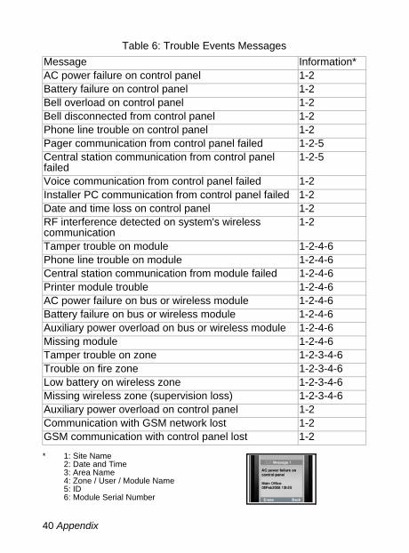
* 1: Site Name2: Date and Time3: Area Name4: Zone / User / Module Name5: ID6: Module Serial Number
Table 6: Trouble Events MessagesMessage Information*AC power failure on control panel 1-2Battery failure on control panel 1-2Bell overload on control panel 1-2Bell disconnected from control panel 1-2Phone line trouble on control panel 1-2Pager communication from control panel failed 1-2-5Central station communication from control panel failed
1-2-5
Voice communication from control panel failed 1-2Installer PC communication from control panel failed 1-2Date and time loss on control panel 1-2RF interference detected on system's wireless communication
1-2
Tamper trouble on module 1-2-4-6Phone line trouble on module 1-2-4-6Central station communication from module failed 1-2-4-6Printer module trouble 1-2-4-6AC power failure on bus or wireless module 1-2-4-6Battery failure on bus or wireless module 1-2-4-6Auxiliary power overload on bus or wireless module 1-2-4-6Missing module 1-2-4-6Tamper trouble on zone 1-2-3-4-6Trouble on fire zone 1-2-3-4-6Low battery on wireless zone 1-2-3-4-6Missing wireless zone (supervision loss) 1-2-3-4-6Auxiliary power overload on control panel 1-2Communication with GSM network lost 1-2GSM communication with control panel lost 1-2

Appendix 41
* 1: Site Name2: Date and Time3: Area Name4: Zone / User / Module Name5: ID6: Module Serial Number
Table 7: Trouble Restore MessagesMessage Information*AC power restored on control panel 1-2Battery power restored on control panel 1-2Bell restored on control panel 1-2Bell connected on control panel 1-2Phone line restored on control panel 1-2Central station communication from control panel restored
1-2-5
Date and time restored on control panel 1-2System wireless communication restored 1-2Tamper restored on module 1-2-4-6Phone line restored on module 1-2-4-6Central station communication from module restored 1-2-4-6Printer module restored 1-2-4-6AC power restored on bus or wireless module 1-2-4-6Battery power restored on bus or wireless module 1-2-4-6Auxiliary power restored on bus module 1-2-4-6Missing module restored 1-2-4-6Tamper restored on module 1-2-3-4-6Fire zone restored 1-2-3-4-6Battery on wireless zone restored 1-2-3-4-6Wireless zone restored 1-2-3-4-6Auxiliary power restored on control panel 1-2Communication with GSM network restored 1-2GSM communication with control panel restored 1-2

42 Appendix
List of SMS Phone NumbersSee “End User SMS Programming” on page 28.
Table 8: SMS Phone Numbers# Phone
NumberPartition Options
01 1: Any Alarm 2: Arming/Disarming3: Any Trouble 4: Any Trouble Restore
02 1: Any Alarm 2: Arming/Disarming3: Any Trouble 4: Any Trouble Restore
03 1: Any Alarm 2: Arming/Disarming3: Any Trouble 4: Any Trouble Restore
04 1: Any Alarm 2: Arming/Disarming3: Any Trouble 4: Any Trouble Restore
05 1: Any Alarm 2: Arming/Disarming3: Any Trouble 4: Any Trouble Restore
06 1: Any Alarm 2: Arming/Disarming3: Any Trouble 4: Any Trouble Restore
07 1: Any Alarm 2: Arming/Disarming3: Any Trouble 4: Any Trouble Restore
08 1: Any Alarm 2: Arming/Disarming3: Any Trouble 4: Any Trouble Restore
09 1: Any Alarm 2: Arming/Disarming3: Any Trouble 4: Any Trouble Restore
10 1: Any Alarm 2: Arming/Disarming3: Any Trouble 4: Any Trouble Restore
11 1: Any Alarm 2: Arming/Disarming3: Any Trouble 4: Any Trouble Restore
12 1: Any Alarm 2: Arming/Disarming3: Any Trouble 4: Any Trouble Restore
13 1: Any Alarm 2: Arming/Disarming3: Any Trouble 4: Any Trouble Restore
14 1: Any Alarm 2: Arming/Disarming3: Any Trouble 4: Any Trouble Restore
15 1: Any Alarm 2: Arming/Disarming3: Any Trouble 4: Any Trouble Restore
16 1: Any Alarm 2: Arming/Disarming3: Any Trouble 4: Any Trouble Restore

Appendix 43
Programming Sections Quick ReferenceFor more detailed information on programming sections, refer to “Configuring the PCS100 Module” on page 11.
Table 9: Installer Programming SectionsDigiplex EVO
SP Series / E65
Value
WinLoad Access Via GPRS [2960] [921] Access Point Name Part 1
[2961] [922] Access Point Name Part 2
[2962] [923] User Name Part 1
[2963] [924] User Name Part 2
[2964] [925] GPRS Password Part 1
[2965] [926] GPRS Password Part 2
[2966] [920] Software Port
[3013] [927] WinLoad TCP/IP/GPRS Password
Text Message (SMS) Notification[2953] [856] SMS Language
[2954] [780] SMS Site Name
Supervision Options[2950] [805] GSM No Service Trouble
Feedback
[2952] [855] GSM No Service Timer
[2950] [805] GSM RF Jamming Supervision
[2951] [884] Control Panel Supervision

44 Appendix
Entering Special CharactersTo enter special characters, press the [mem] key on the EVO641 or EVO641R keypad. The line will turn to a square, then enter the digit code for the character you wish to enter.

45
IndexA
Access Point Name ..................... 12Account Number(s) ..................... 14Alarm Messages ......................... 38Antenna .....................................4, 8Antenna Extension ........................ 8APN Password ............................ 12APN User Name ......................... 12Arming Disarming Messages ....... 39
B
Bandwidth ..................................4, 9
C
Cancel SMS ................................ 30Configuring WinLoad Access ....... 13Connecting to the GPRS Network 11Connections .................................. 6Control Panel Supervision ........... 35Current consumption ..................... 4
D
Data encryption ............................. 4Digiplex Evo ................................ 14
E
End User SMS Programming ....... 28
F
Firmware .................................... 31Firmware Upgrade ...................... 31Firmware upgrade ....................... 31
G
GPRS ..................................... 3, 10GPRS Connection Settings .......... 13GPRS Reporting .......................... 38GSM Network Provider Information 11GSM No Service Trouble ............. 34GSM RF Jamming Supervision ..... 34
I
IMEI .............................................. 5In-field firmware programmer ........ 37In-field firmware upgrade ............. 31Installation ..................................... 5Installer Software Password ......... 13IP Address .................................. 14IP Information .............................. 29IP Port(s) ..................................... 14IP Receiver registration status 18, 23IP Reporting .......................... 15, 21IP Troubles ............................ 19, 24IP/GPRS Reporting partitions ....... 15
J
Jamming ........................... 3, 10, 34
L
Language .................................... 27LED ............................................ 10
M
Master Programming ................... 28Mounting ....................................... 8

46
N
Notification .................................. 26
O
On-site firmware upgrade ............. 31On-Site Upgrade ......................... 31Operating temperature ................... 4Output power ................................ 4
P
PGM Events .......................... 19, 24Private Network ........................... 36Programming and Registration 14, 20Public Network ............................ 36
R
Receiver Password(s) .................. 14Registration ........................... 14, 20Remote firmware upgrade ............ 32Report .................................... 3, 26Report code format ...................... 14
S
Security Profile(s) ........................ 14Signal Strength Indicators ............ 10SIM Card ................................ 5, 36Site Name ................................... 27SMS ..................................... 26, 37SMS Language ........................... 27SMS protocol ................................ 4SMS Site Name ........................... 27SMS Text Message ..................... 37Software Port .............................. 13SP Series .................................... 20Special Characters ...................... 44Status LED .................................. 10
Supervision ....................... 3, 34, 35
T
Technical Specifications .................4Text Message ..............................26Trouble Events Messages ............40Trouble Restore Messages ...........41
U
Upgrade ..................................3, 31
W
WinLoad ................................11, 36

47
NOTES__________________________________________________________________________________________________________________________________________________________________________________________________________________________________________________________________________________________________________________________________________________________________________________________________________________________________________________________________________________________________________________________________________________________________________________________________________________________________________________________________________________________________________________________________________________________________________________________________________________________________________________________________________________________________________________________________________________________________________

We hope this product performs to your complete satisfaction. Should you have any questions or comments, please us at visit www.paradox.com.
PARADOX.COM
Printed in Canada 10/2008 PCS100G-EI01