paragon gas injector installation and performance … gas injector installation and performance...
TRANSCRIPT

Paragon Gas Injector Installation and Performance Report
International SEMATECH Technology Transfer #03084423A-TR

© 2003 International SEMATECH, Inc.
International SEMATECH and the International SEMATECH logo are registered service marks of International
SEMATECH, Inc., a wholly-owned subsidiary of SEMATECH, Inc.
Product names and company names used in this publication are for identification purposes only and may be trademarks or service marks of their respective companies.

Paragon Gas Injector Installation and Performance Report Technology Transfer #03084423A-TR
International SEMATECH December 12, 2003
Abstract: This document reports an evaluation of the Paragon gas injector at International SEMATECH. The Paragon gas injector was installed in 1994 to support a metal etch process. Details of the pilot test installation and a history of its 9-year performance are presented.
Keywords: Boron Compounds, Nitrogen, Yield, Moisture, Vacuum, Pumps, Equipment Performance, Gas Pressure
Authors: Robert Sherman
Approvals: Robert Sherman, Author Walter Worth, ESH Project Manager Paul Fowler, ISMT Facilities Engineering Manager Tom Wear, ISMT Facilities Manager Laurie Modrey, Technical Information Transfer Team Leader


iii
International SEMATECH Technology Transfer #03084423A-TR
Table of Contents
1 EXECUTIVE SUMMARY .................................................................................................1
2 INSTALLATION BACKGROUND....................................................................................1
3 OVERVIEW.......................................................................................................................2
4 PARAGON GAS INJECTOR DESIGN AND THEORY OF OPERATION.........................5 4.1 Technical Problem.....................................................................................................5 4.2 Mechanism of Ductwork Deposition..........................................................................5 4.3 Effects of Ductwork Deposition.................................................................................6 4.4 Design .......................................................................................................................6 4.5 Theory of Operation ..................................................................................................7
5 CONVENTIONS..............................................................................................................10
6 ISMT PILOT TEST .......................................................................................................... 11 6.1 Installation............................................................................................................... 11 6.2 Performance and Observations.................................................................................13
7 COST, ENERGY EFFICIENCY, AND RESOURCE CONSERVATION CONSIDERATIONS ........................................................................................................15 7.1 Point of Use Control Systems ..................................................................................15 7.2 Resource Consumption Comparison ........................................................................16 7.3 Effect on Corporate Energy Consumption................................................................17 7.4 Test Conclusions .....................................................................................................18
7.4.1 Lessons Learned: Installation Practices ........................................................18

iv
Technology Transfer #03084423A-TR International SEMATECH
List of Figures
Figure 1 Conventional Vacuum Pump Exhaust Installation...................................................2
Figure 2 Conventional Vacuum Pump Exhaust Installation with Post Treatment ...................2
Figure 3 Flow Profile ...........................................................................................................6
Figure 4 Basic Gas Injector Design ......................................................................................7
Figure 5 Paragon Duct Injector.............................................................................................8
Figure 6 High Flow Back Pressures of Gas Injector..............................................................9
Figure 7 Line Clogging Back Pressure Drop ......................................................................10
Figure 8 ISMT Pilot Test Diagram...................................................................................... 11
Figure 9 Duct Injector Installation Diagram .......................................................................12
Figure 10 ISMT Pilot Test Installation..................................................................................12
Figure 11 Particle Fouling of Duct Injector ..........................................................................13
Figure 12 Particle Build-up in Duct Injector.........................................................................14
Figure 13 Exhaust Duct Particle Accumulation ....................................................................15
Figure 14 Annual Costs of EOP Abatement Systems ............................................................16
Figure 15 Annual Water Use and CO2 Generation of EOP Abatement Systems.....................17

v
International SEMATECH Technology Transfer #03084423A-TR
List of Tables
Table 1 LPCVD and PECVD Processes .................................................................................4
Table 2 Comparison of Corporate Energy Consumption .......................................................18
vi
Technology Transfer #03084423A-TR International SEMATECH
Acknowledgments
John C. Schumacher Schumacher Technology, CEO
Dennis Hanslik International SEMATECH, Maintenance Technician
Tommy Crayton International SEMATECH, Facilities Operations
1
International SEMATECH Technology Transfer #03084423A-TR
1 EXECUTIVE SUMMARY
This document reports the pilot test installation and evaluation of the Paragon gas injector designed to eliminate clogging caused by moisture backstreaming into the vacuum exhaust line of a semiconductor device fabrication tool. The Paragon gas injector was installed at International SEMATECH (ISMT) in 1994 to support a metal etch process. In the 9 years since it was installed, there have been no reports of particle contamination or exhaust clogging interrupting the metal etch process. Most observations suggest that using proper installation practices will ensure the device’s successful operation.
Compared to a point of use (POU) abatement device, the Paragon gas injector can reduce capital cost by as much as $120,000 and operating cost by up to $32,000. Mean time between maintenance (MTBM) and/or tool shutdown can also exceed 12 months.
By eliminating moisture backstreaming, the gas injector avoids the deposition thought to cause particle shower contamination in process reaction chambers. As a result, it can enhance process control and device yield. Thus, the Paragon can potentially lower installation costs and post-installation maintenance, resource consumption, and operating costs while improving efficiency and reliability.
2 INSTALLATION BACKGROUND
About 1991, SEMATECH’s etch vacuum pump exhaust piping systems started to clog with increasing frequency. An all-inclusive remedy for the problem was not easily found.
The etch vacuum pump exhaust lines connect the process exhaust to a common lateral header containing exhaust from a number of disparate processes. This header in turn is connected to a main acid exhaust line, which is then routed to the plant scrubber/fan systems. The chemical reactions in such an interconnected system are varied and complex, hindering identification of the source of the clogging.
In 1991, clogging was not the only exhaust system problem. Oil was also being discharged into the exhaust laterals and main headers. Typically, valves were installed on the vacuum exhaust lines to stop this oil migration. This increased line pressure drop and slowed pumping speeds. An inadvertent closing of these valves would have been catastrophic.
One remedy was to install an “air gap” on the vacuum pump exhaust line just before the connection to the exhaust lateral to provide self-balancing. The design mimicked the air gap on an acid drain system used for drain venting to the acid exhaust system. But in 1991, with wet vacuum pumps gradually being replaced by dry vacuum pumps without oil and hard vacuum valving being replaced with soft valving, air gaps were no longer implemented; however, many were still in place.
In 1993, a vacuum pump exhaust line supporting a metal plasma etch system clogged at the point where it entered the exhaust air gap. The vacuum pump went into back pressure alarm, shut down the process, blew boron oxide particulate throughout the maintenance space, and emitted boron trichloride and chlorine odors, sounding the gas alarm to evacuate the entire fab. This occurred without any warning that the system was experiencing problems.
Almost immediately after this incident, the Paragon gas injector became available. SEMATECH pilot tested the device with the hope of eliminating its line clogging problem. The decision was

2
Technology Transfer #03084423A-TR International SEMATECH
made to install the Paragon on the vacuum pump exhaust system of the troubled metal plasma etch reaction chamber.
3 OVERVIEW
The Paragon gas injector (USP 6,432,372) was designed to eliminate clogging caused by moisture backstreaming into the vacuum exhaust line of a semiconductor device fabrication tool. Table 1 is a partial list of processes carried out in such tools, along with process chemistries and post-pump abatement systems typically employed.
Candidate gas injector applications include conductor deposition and etch processes such as metal/poly/tungsten etch and deposition. These processes are Paragon candidates because (1) they use moisture-sensitive but not flammable or explosive reactants, and (2) they exhibit the greatest negative impact of particulate contamination on device yield of all processes on the list.
Both moisture backstreaming and the resultant clogging occur at the vacuum exhaust system’s point of entry into moisture sources such as depicted in Figure 1 and Figure 2. Such sources include the facilities scrubbed exhaust as well as point of use (POU) wet scrubbers and dynamic or thermal oxidation units.
Figure 1 Conventional Vacuum Pump Exhaust Installation
Figure 2 Conventional Vacuum Pump Exhaust Installation with Post Treatment

3
International SEMATECH Technology Transfer #03084423A-TR
POU scrubber units have often been used to mitigate vacuum exhaust clogging and particulate contamination. However, because of cost penalties and inefficient consumption of scarce resources, they should be restricted to only those applications requiring scrubbing or converting highly toxic and flammable gas mixtures.
By eliminating moisture backstreaming, the gas injector avoids the deposition thought to cause particle shower contamination in process reaction chambers. As a result, it can enhance process control and device yield. Thus, the Paragon can potentially lower installation costs and post-installation maintenance, resource consumption, and operating costs while improving efficiency and reliability.

International SEMATECH Technology Transfer #03084423A-TR 4
Table 1 LPCVD and PECVD Processes*
# Temp oC Physics OEM Process Deposition Chemistry (sccm) Etch Chemistry (sccm) POU (97093364) Facility VET
1 1000 ASM Epi SiH4 (1000) H2 (200 SLM) NA WS + Vent or TO Dilution
2 AMT Eat Implant AsH3 PH3 B2H6 BF3 NA DS CRCS
3 550–650 LPCVD SVG ASM Poly SiH4 (200) NA Not Covered WS
4 425 Max PECVD Novellus Poly SiH4 (200) C2F6 TO +WS WS
5 425 Max PECVD Novellus Doped Poly SiH4 (120) PH3 (15) ClF3 TO +WS WS
6 PE Lam AMT SWR Poly Etch HBr (200) Cl2 (200) SF6 (100)CF4(100)HeO2 (20) DS or WS WS
7 PE Lam AMT SWR Al Etch BCl3 (100) Cl2(100) SF6 (200) CF4 (50) DS or WS WS
8 Lam Al Etch BCl3 (52) Cl2 (93) SF6 (30) He (19) DS or WS WS
9 350 PECVD Genus WSi WF6 (100) SiH4 (300) H2 (2000) NA Not Covered WS
10 350 PECVD Novellus WSi WF6 (300) SiH4 (40) H2 (17000) Ar C2F6 (1200) O2 (1200) Not Covered WS
11 350 PECVD Genus W WF6 (100) H2 (2000) NA Not Covered WS
12 350 PECVD Novellus W WF6 (100) H2 (2000) Ar C2F6 O2 DS or TO+WS WS
13 PE Novellus W Etchback C2F6 O2 Not Covered WS
14 750 LPCVD SVG ASM SWR Nitride SiH4 (600) NH3 (300) NA TO +WS WS
15 750 LPCVD SVG ASM Batch Nitride SiH2Cl2 (100) NH3 (600) NA DS or TO+WS Dilution
16 450 Max PECVD Novellus Nitride SiH4 (600) NH3 (5000) C2F6 (1600) O2 (1600) TO +WS WS
17 450 Max PECVD AMT Nitride SiH4 (600) NH3 (300) N2O CF4 TO +WS WS
18 700–725 LPCVD ASM Oxynitride SiH4 (650) O2 (500) NH3 (8000) C2F6 O2 Not Covered WS
19 725 LPCVD SVG ASM Oxide TEOS (2.5 gpm) NA DS or TO+WS Dilution
20 340 PECVD Novellus Oxide TEOS (1.2 gpm) O2 (2000) C2F6 DS or TO+WS WS
21 375–425 PECVD AMT Oxide TEOS (1.2 gpm) O2 (1500) Ar CHF3 CF4 DS or TO+WS WS
22 375–400 LPCVD SVG ASM LTO SiH4 (120) N2O (60) NA DS or TO+WS Dilution
23 325 PECVD Novellus LTO SiH4 (220) N2O (5000) C2F6 (1600) O2 (1600) Not Covered
24 325 PECVD Novellus LTO SiH4 (120) O2 (2000) C2F6 DS or TO+WS WS
25 325 PECVD Novellus LTO SiH4 (120) O2 (240) C2F6 DS or TO+WS WS
26 325 PECVD AMT LTO SiH4 (120) O2 (350) NF3 O2 DS or TO+WS WS
27 725 LPCVD SVG ASM BPSG TEOS (2.5 gpm) O2 (400) PH3 (30) TMB (30) NA DS or TO+WS WS
28 400 LPCVD ASM LTPSG SiH4 (120) O2 (240) PH3 (15) C2F6 O2 Not Covered WS
* Source: J.C. Schumacher, inventor

5
International SEMATECH Technology Transfer #03084423A-TR
4 PARAGON GAS INJECTOR DESIGN AND THEORY OF OPERATION
4.1 Technical Problem
Solutions to the vacuum exhaust clogging problem in semiconductor device fabrication deposition and etch tools, especially metal etch, began to be sought1 in the late 1980s. According to industry experts2, a solution was needed because MTBM on such tools was too short. In fact, the 2-inch piping between the vacuum pump and the house-scrubbed exhaust had to be replaced after every 1000 wafers processed because it became so clogged that pump backpressure approached 1 psi. Overpressure alarms would trigger at 3 psi, causing unscheduled shut downs and lost wafers.
4.2 Mechanism of Ductwork Deposition
Reactants cause extensive ductwork deposition in process such as dichlor-nitride in which unreacted source materials (dichlorosilane) SiCl2H2 and (ammonia) NH3 form ammonium chloride deposits and in TEOS oxide deposition in which thermal decomposition of unreacted TEOS source material and reaction with moisture cause SiO2 or polymerized TEOS formation and deposition, respectively. Ductwork deposition for these processes is initiated just downstream of the process tool by the following reactions:
1. Dichlor-Nitride Process
3 SiCl2H2 + 10 NH3 ↔ Si3N4 + 6 NH4Cl + 6 H2
2. TEOS Oxide Deposition Process3
Si(OEt)4 ↔ SiO2 + 2 H2O + 4 C2H4
Si(OEt)4 + H2O → (Si(OEt)2)n
In conductor deposition and etch processes, however, ductwork deposition occurs from the condensation of reaction product as well as the backstreaming of moisture vapor from a downstream source. Condensable reaction products for these processes include solid AlCl3 as well as liquid SiHBr3 and WF6.
Moisture sources include water scrubbers, burn boxes, or the house-scrubbed exhaust duct; deposits form just upstream of such moisture sources.
Duct deposition chemical reactions based on backstreaming from such sources include the following:
1. Aluminum Etch Process
1.5 Cl2 + Al +2 BCl3 + 3 H2O ↔ AlCl3(↓ ) + B2O3(↓ )
2. Poly Etch Process
Si + 3 HBr + 2 H2O ↔ SiHBr3 + H2 + 2 H2O ↔ SiO2(↓ ) + 3 HBr
3. Tungsten Etch or Etch Back Process
3 W + 2 CF4 + 6 H2O ↔ WOF4(↓ ) + CxFyHz + WO2F2(↓ ) + WO3(↓ )
1 J.C. Schumacher, CEMI Sergeant Burn Box Sales Meetings at DEC, TI, IBM and Hyundai 2 Karl Koch, DEC 3 For a more detailed discussion see
http://www.batnet.com/enigmatics/semiconductor_processing/CVD_Fundamentals/films/TEOS_O2_thermal.html

6
Technology Transfer #03084423A-TR International SEMATECH
4. Tungsten Deposition Process
3 WF6 + 6 H2O ↔ WOF4(↓ ) + CxFyHz + WO2F2(↓ ) + WO3(↓ )
Such backstreaming moisture reactions occur when certain molecules (H2O, Cl2, etc.) move upstream in the exhaust system duct from a moisture or other source (scrubbed exhaust, combustion system etc.) countercurrent to the predominant flow of gas moving downstream (i.e., called “backstreaming” because of the countercurrent nature of flow). The electrochemical potential driven “need” of chemical species to equalize their concentration throughout all space to which they are connected is the driving force for the countercurrent flow. This upstream flow occurs by molecular diffusion in the slowly moving boundary layer seen in Figure 3, which represents the transition between the high velocity turbulent gas stream and the stationary pipe wall.
Figure 3 Flow Profile
Deposition (clogging) subsequently occurs when species upstream in the vapor phase process exhaust form a solid by reacting with those in the boundary layer as a result of backstreaming.
4.3 Effects of Ductwork Deposition
When the vacuum exhaust clogs, two major problems appear:
1. Over time, clogging of lines creates system backpressure, increased pressure drop and vacuum pumpdown time, frequent “clean up” maintenance, loss of product, process downtime, and increased costs. In some cases, vacuum pump alarms are initiated because of increased backpressure and entire production areas, even entire manufacturing factories, are evacuated. This contributes significantly to loss of time and money.
2. Particulate showers can also occur in the process chamber, degrading product yield and resulting in product loss, cross-contamination with other process equipment, clean up maintenance, process downtime, and increased costs. This is a top contributor to yield degradation in processes that use moisture-sensitive materials and are prone to severe vacuum exhaust line clogging.
4.4 Design
According to its designer (Schumacher Technology), the Paragon gas injector (USP 6,432,372) prevents moisture backstreaming by eliminating turbulence at the periphery of flow where the vacuum exhaust enters the moisture source. It also simultaneously provides a nitrogen blanket diffusion barrier that surrounds non-reacted gases in the vacuum pump exhaust while they enter the moisture source. Solids are therefore formed in the moisture source rather than upstream from it, preventing clogging of the vacuum exhaust.
7
International SEMATECH Technology Transfer #03084423A-TR
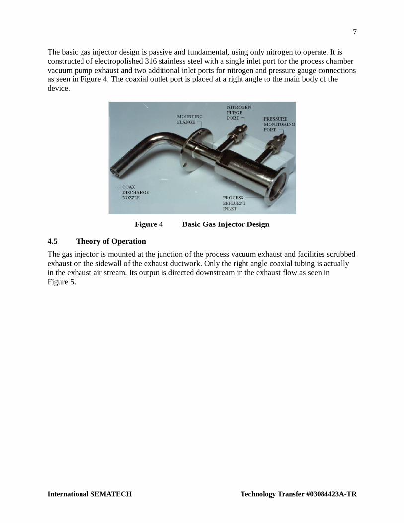
The basic gas injector design is passive and fundamental, using only nitrogen to operate. It is constructed of electropolished 316 stainless steel with a single inlet port for the process chamber vacuum pump exhaust and two additional inlet ports for nitrogen and pressure gauge connections as seen in Figure 4. The coaxial outlet port is placed at a right angle to the main body of the device.
Figure 4 Basic Gas Injector Design
4.5 Theory of Operation
The gas injector is mounted at the junction of the process vacuum exhaust and facilities scrubbed exhaust on the sidewall of the exhaust ductwork. Only the right angle coaxial tubing is actually in the exhaust air stream. Its output is directed downstream in the exhaust flow as seen in Figure 5.

8
Technology Transfer #03084423A-TR International SEMATECH
Figure 5 Paragon Duct Injector
The process effluent discharges from the internal coax tubing while nitrogen is discharged between the inside and outside coaxial tubes (the annulus).
Delayed reactions between elements of the process effluent and scrubbed exhaust are caused by the laminar flow of nitrogen between the two streams in the coaxial annular area. The nitrogen effectively surrounds the process effluent gases upon exit from the Paragon injector while entering the exhaust air stream, thus creating a diffusion barrier to reaction.
The distance from the end of the injector to the point of initial reaction between process effluent and exhaust stream is called the “stand-off” distance inside the exhaust stream. This distance is a function of the nitrogen, process effluent and exhaust flow type, and velocity. Schumacher testing using a process effluent of 500 sccm of BCl3 has shown effective stand-off distances ranging from 1 to 3 inches with nitrogen velocity between 22 and 44 feet per second, (i.e., 1 to 2 standard cubic feet per minute) and an exhaust velocity between 900 and 1800 feet per minute. Figure 11 shows the actual Paragon installation and “stand off” at ISMT.
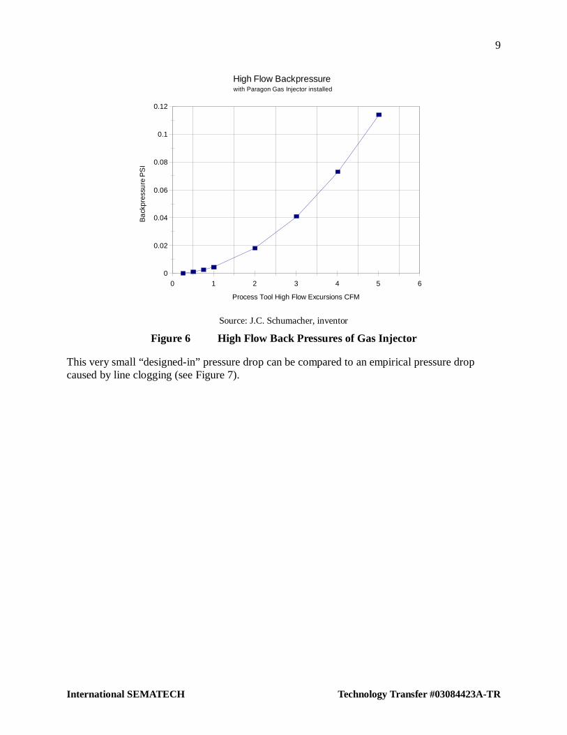
The Paragon gas injector restricts the flow entering into the vacuum exhaust (as can be seen in Figure 5) to control relative duct, barrier, and process effluent velocities. However, the resultant pressure drop is too small to cause overpressure as seen from calculations summarized in Figure 6.
9
International SEMATECH Technology Transfer #03084423A-TR
0
0.02
0.04
0.06
0.08
0.1
0.12
Ba
ckpr
essu
re P
SI
0 1 2 3 4 5 6
Process Tool High Flow Excursions CFM
High Flow Backpressurewith Paragon Gas Injector installed
Source: J.C. Schumacher, inventor
Figure 6 High Flow Back Pressures of Gas Injector
This very small “designed-in” pressure drop can be compared to an empirical pressure drop caused by line clogging (see Figure 7).

10
Technology Transfer #03084423A-TR International SEMATECH
AME04_PP(psi)3
2
1
0
39 Exhaust pressure (psi)
9/1/0000:00:00
9/3/0000:00:00
9/5/0000:00:00
9/7/0000:00:00
9/9/0000:00:00
9/11/0000:00:00
9/13/0000:00:00
Source: J.C. Schumacher, inventor
Figure 7 Line Clogging Back Pressure Drop
One final designed-in pressure drop concern was the high flow rates seen during pumpdown. An analysis using the Paragon pressure drop and a vacuum pump having an initial capacity of 48 cubic feet and a pumping speed of 15 cubic feet per minute showed that back pressures created by the installation was less than 0.1 inch water column (wc). However, in simulated large volume high speed pumpdowns, back pressures up to 10 psi were seen, although for very short times. The supplier, Schumacher Technology, states that Paragon injectors can be manufactured in larger sizes, as required, with less pressure drop to ensure normal operations when using higher speed vacuum pumps.
5 CONVENTIONS
Many semiconductor installations typically route the reaction chamber vacuum pump exhaust directly to their facilities scrubbed (acid) exhaust system. This is sometimes done without considering the potential reactions between species in the effluent and those in the exhaust system.
When incompatible chemistries raise concerns, POU post-pump treatment devices are installed on the vacuum line between the vacuum pump and the facility exhaust system. This may be done without studying the chemistries involved. Although POU abatement devices may resolve many reactions possible in the exhaust duct, they have capital, installation, and operating costs.
11
International SEMATECH Technology Transfer #03084423A-TR
6 ISMT PILOT TEST
6.1 Installation
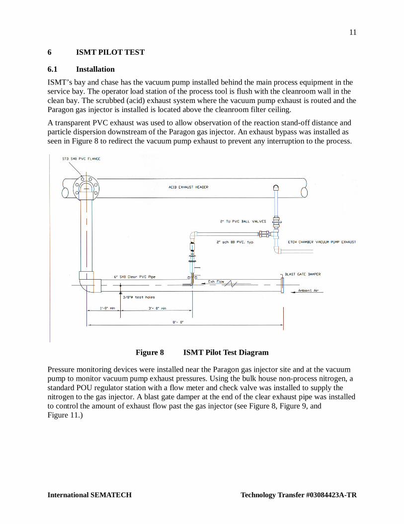
ISMT’s bay and chase has the vacuum pump installed behind the main process equipment in the service bay. The operator load station of the process tool is flush with the cleanroom wall in the clean bay. The scrubbed (acid) exhaust system where the vacuum pump exhaust is routed and the Paragon gas injector is installed is located above the cleanroom filter ceiling.
A transparent PVC exhaust was used to allow observation of the reaction stand-off distance and particle dispersion downstream of the Paragon gas injector. An exhaust bypass was installed as seen in Figure 8 to redirect the vacuum pump exhaust to prevent any interruption to the process.
Figure 8 ISMT Pilot Test Diagram
Pressure monitoring devices were installed near the Paragon gas injector site and at the vacuum pump to monitor vacuum pump exhaust pressures. Using the bulk house non-process nitrogen, a standard POU regulator station with a flow meter and check valve was installed to supply the nitrogen to the gas injector. A blast gate damper at the end of the clear exhaust pipe was installed to control the amount of exhaust flow past the gas injector (see Figure 8, Figure 9, and Figure 11.)

12
Technology Transfer #03084423A-TR International SEMATECH
Figure 9 Duct Injector Installation Diagram
Figure 10 ISMT Pilot Test Installation
Schumacher Technology, the supplier of the Paragon gas injector, determined that the exhaust velocity should be approximately 1000 feet per minute and nitrogen fed to the injector should be 1 cubic foot per minute regulated to 5–10 psig. The nitrogen flow rate was critical. Laminar flow needed to be maintained at the exit of the gas injector for correct operation. Turbulent eddy currents would disrupt the nitrogen boundary layer, resulting in moisture reaction and rendering the gas injector useless. The vacuum pump exhaust effluent from the metal plasma etch process was typically 0.1 to 2 liters per minute.

13
International SEMATECH Technology Transfer #03084423A-TR
Pressure was monitored using Dwyer magnahelics with a range of 0–3-inch wc. The “Lo” side connections were piped to the Paragon gas injector and the “Hi” sides opened to ambient. The indicated pressures read were negative gauge pressures.
The pilot test installation was ready for service in early Q3/94.
6.2 Performance and Observations
The magnahelic exhaust pressure was benchmarked, keeping the exhaust on by-pass, before placing the gas injector on line. The magnahelic readings indicated a total static pressure of negative 2.75-inch wc in the 6-inch clear exhaust pipe without any flow. The nitrogen flow and pressures were set and the exhaust blast gate damper was balanced to 1050 fpm velocity. The magnahelic reading was negative 2.6-inch wc exhaust pressure.
With the vacuum pump operating and the Paragon gas injector online, the magnahelic reading dropped to 2-inches wc. Within an hour, a visible particulate dispersion began depositing on the inside wall of the clear exhaust pipe approximately 4–5 inches downstream of the end of the gas injector nozzle, as expected.
Figure 11 Particle Fouling of Duct Injector
However, oil residue combined with boron oxide then began discharging from the exit nozzle of the gas injector and dripping into the clear exhaust duct, fouling the duct injector with a substance similar in look and consistency to Elmer’s Glue see (Figure 11). The magnahelic pressure readings also showed a pressure decay. After bypassing to the exhaust system, the gas injector was removed and cleaned. The vacuum pump was determined to have bad seals and was replaced, and the vacuum pump exhaust piping, which had contained a previous buildup of boron oxide, was also replaced.
Several days later (Q4/1994), a steady decay in exhaust pressure was noticed. Thereafter, performance of the gas injector was as specified. Some white powder buildup could be seen inside the tip of the Paragon gas injector discharge. The gas injector was therefore bypassed and removed for inspection. An outboard moisture leak was suspected in the pressure gauge mechanical fittings or in the pressure gauge itself. Boron oxide deposits hazed the inside of the gas injector with most particle buildup near and inside the pressure port (see Figure 12). The Paragon gas injector was cleaned and the duct injector pressure port was capped.

14
Technology Transfer #03084423A-TR International SEMATECH
Figure 12 Particle Build-up in Duct Injector
Several years later, a huge amount of boron oxide buildup was seen at the discharge nozzle of the gas injector. On inspection, the entire internal surface of the Paragon gas injector was found to be coated and the discharge nozzle was 95% plugged with hardened boron oxide. When the exhaust piping was inspected, it was found to be almost entirely coated from a slight haze to approximately a ¼-inch buildup near the vacuum pump. All exhaust piping was either cleaned or replaced. An informal investigation concluded that a gradual leak had occurred. However, no information about chamber particles, vacuum pumping speeds, or back pressures had been logged or discussed during this time. A new Paragon gas injector was installed, again leaving the pressure port capped.
Operation without interruption continued until Q3/2000. At this time, the ISMT-fabricated Paragon gas injector mounting flange attached to the clear exhaust duct became loose and outboard ambient air began leaking into the scrubbed exhaust at the gas injector connection. This did not pose a threat to the process or require that the gas injector be removed for cleaning.4 The Paragon gas injector has remained in operation since.
Finally, dispersions of the B2O3 particles that formerly clogged the vacuum exhaust were expected on the inner walls of the exhaust duct. The internal coating can be seen in Figure 13. This represents 8 to 9 years of particle buildup starting just downstream of the gas injector discharge nozzle. Initial particle pluming dispersions on the inner duct walls can be seen in Figure 11.
4 Schumacher Technology currently provides a duct adapter for each installation that avoids this problem

15
International SEMATECH Technology Transfer #03084423A-TR
Figure 13 Exhaust Duct Particle Accumulation
Each potential user must evaluate the relative consequences of total obstruction of the smaller vacuum exhaust pipe vs. the thin particle coatings in the larger exhaust duct as a result of Paragon use. Large exhaust ducts will take much longer to become clogged by particle buildup (if they clog at all), and preventative maintenance can be scheduled with much less frequency. The rate of particle build up is a function of the process production time.
7 COST, ENERGY EFFICIENCY, AND RESOURCE CONSERVATION CONSIDERATIONS
Energy efficiency and resource conservation have become critical issues in the semiconductor industry from both a public relations and financial competitive advantage perspective. Consequently, alternative methods of solving the metal deposition and etch MTBM issue were compared after studying the ductwork deposition question.
Technology Transfer #95022713A-ENG, Global Warming Studies: Global Warming Impact Model, evaluates resource consumption by POU effluent treatment systems used to abate perfluorocarbon (PFC) emissions.
Based on corporate information in the public domain and this document, POU abatement systems used extensively throughout the device fabrication process represent a sizable fraction (1% to 2%) of total corporate energy and resource consumption.
7.1 Point of Use Control Systems
POU control systems were first used for semiconductor device fabrication at HP in the early 1980s. Before then, end-of-pipe (EOP) abatement systems, typically composed of a large water scrubber fed by a house exhaust system that collected effluent from an entire facility, controlled air pollution and protected in-house personnel. At HP, Innovative Engineering Corporation of San Jose, CA, introduced its POU controlled oxidation and decomposition (CDO) reactor. They claimed improved POU destruction of flammable and explosive hydride gases, SiH4, PH3 and B2F6, over EOP facility type wet scrubber technology.

16
Technology Transfer #03084423A-TR International SEMATECH
Local air quality management organizations and fire marshals were quick to seize upon the reduced air pollution potential and improved facility safety features of the POU devices and to require them, through UFC Article 80, in new construction projects planned by the semiconductor industry as part of their environment, safety, and health (ESH) mission.
7.2 Resource Consumption Comparison
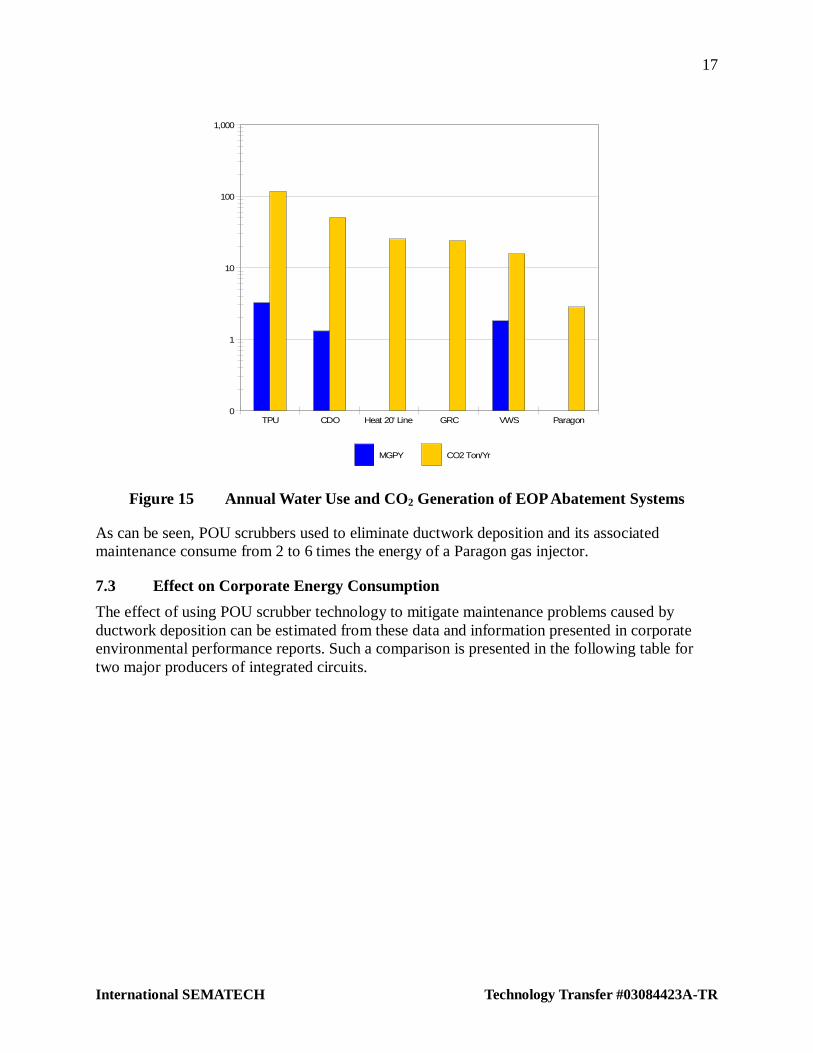
The methodology and data in Technology Transfer #95022713A-ENG allow one to compare annual energy and operating costs (Figure 14), and water consumption and global warming gas generation (Figure 15) for various schemes used to minimize exhaust ductwork deposition.
0
10,000
20,000
30,000
40,000
50,000
60,000
70,000
TPU CDO Heat 20' Line GRC VWS Paragon
Annual KWH/Yr Annual Operating Cost $
Figure 14 Annual Costs of EOP Abatement Systems
17
International SEMATECH Technology Transfer #03084423A-TR
0
1
10
100
1,000
TPU CDO Heat 20' Line GRC VWS Paragon
MGPY CO2 Ton/Yr
Figure 15 Annual Water Use and CO2 Generation of EOP Abatement Systems
As can be seen, POU scrubbers used to eliminate ductwork deposition and its associated maintenance consume from 2 to 6 times the energy of a Paragon gas injector.
7.3 Effect on Corporate Energy Consumption
The effect of using POU scrubber technology to mitigate maintenance problems caused by ductwork deposition can be estimated from these data and information presented in corporate environmental performance reports. Such a comparison is presented in the following table for two major producers of integrated circuits.

18
Technology Transfer #03084423A-TR International SEMATECH
Table 2 Comparison of Corporate Energy Consumption*
Company A Company B
GWh 1774 2600
Tons CO2/Year 1,000,000 1,465,614
6"wafers 5,656,233 10,148,046
KWh/6"wafer 314 256
Metal Etch POU Units 237 425
Units/wafer 0.00004 0.00004
KWh/Unit 69,407 69,407
KWh 16,441,341 29,497,986
% kWh 0.93% 1.13%
Tons of CO2 12,084 21,681
% Tones of CO2 1.21% 1.48%
* Source: J.C. Schumacher, inventor
7.4 Test Conclusions
In the last 9 years since the Paragon gas injector was installed, there have been no reports of process interruption because of metal etch tool particle contamination or exhaust clogging. Most observations suggest that using proper installation practices will provide and maintain a successful Paragon gas injector installation.
7.4.1 Lessons Learned: Installation Practices
Use a post-pump destructive or scrubber abatement device(s) if effluent gases are highly toxic and/or flammable non-reacted byproducts. Check resident ESH guidelines, local fire marshal rulings, local and state codes, National Fire Protection Association (NFPA), Hazardous Occupancy Code (H6), and consult the authority having jurisdiction for the fab.
Install the Paragon gas injector on process chamber vacuum pump exhaust lines using any moisture reactive gases. Install either at the junction of the exhaust duct or (if highly toxic or flammable gas destruction is required) at the inlet to the post-pump abatement device.
All piping connected to the Paragon gas injector should be free of leakage: 1. Use low grade thin wall stainless steel tubing with welded joints on the vacuum pump
exhaust. Using a minimum of mechanical connections will minimize outboard ambient moisture leakage. Assure that all systems are leak-checked.
2. Use VCR mechanical fittings on the pressure gauge and nitrogen port piping. Minimize mechanical fitting use as much as practical. Assure that all systems are leak-checked (note: Paragon units are now supplied with welded VCR fittings from the factory).
3. Use a non-permeable pressure monitoring device. Some devices use elastometer diaphragms and will be prone to outboard moisture permeation.
19
International SEMATECH Technology Transfer #03084423A-TR
To ensure a stand-off distance of 1”–6” from the end of the Paragon gas injector discharge nozzle in the exhaust stream,
1. Assure that the exhaust stream across the gas injector is operating in the velocity range of 900 to 1800 feet per minute.
2. Assure that the nitrogen flow is operating at 1 standard cubic foot per minute and regulated to 5–10 pounds per square inch gauge pressure.
3. Set the vacuum pump reaction chamber effluent exhaust gas flow nominally between 0.5–2.5 standard cubic feet per minute (14 to 71 standard liters per minute). This includes all combined gas flow mixtures being evacuated from the chamber, inert, reacted, and non-reacted byproducts.
4. Avoid use of existing vacuum pump exhaust piping when retrofitting the Paragon gas injector to an existing system. Replace all piping.
5. Check reliability and operation of existing vacuum pump systems. Review past maintenance records.


International SEMATECH Technology Transfer 2706 Montopolis Drive
Austin, TX 78741
http://www.sematech.org e-mail: [email protected]