parallax360: stereoscopic 360° scene representationfor ... › publications › parallax360 ›...
TRANSCRIPT
Parallax360: Stereoscopic 360° Scene Representationfor Head-Motion Parallax
Bicheng Luo, Feng Xu, Christian Richardt and Jun-Hai Yong
(a)
(b) (c)
(d) (e)
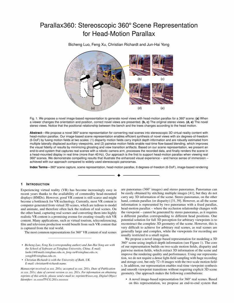
Fig. 1. We propose a novel image-based representation to generate novel views with head-motion parallax for a 360° scene: (a) Whena viewer changes the orientation and position, correct novel views are presented. (b, c) The original stereo views. (d, e) The novelstereo views. Notice that the positional relationship between the bench and the trees changes according to the head motion.
Abstract—We propose a novel 360° scene representation for converting real scenes into stereoscopic 3D virtual reality content withhead-motion parallax. Our image-based scene representation enables efficient synthesis of novel views with six degrees-of-freedom(6-DoF) by fusing motion fields at two scales: (1) disparity motion fields carry implicit depth information and are robustly estimated frommultiple laterally displaced auxiliary viewpoints, and (2) pairwise motion fields enable real-time flow-based blending, which improvesthe visual fidelity of results by minimizing ghosting and view transition artifacts. Based on our scene representation, we present anend-to-end system that captures real scenes with a robotic camera arm, processes the recorded data, and finally renders the scene ina head-mounted display in real time (more than 40 Hz). Our approach is the first to support head-motion parallax when viewing real360° scenes. We demonstrate compelling results that illustrate the enhanced visual experience – and hence sense of immersion –achieved with our approach compared to widely-used stereoscopic panoramas.
Index Terms—360° scene capture, scene representation, head-motion parallax, 6 degrees-of-freedom (6-DoF), image-based rendering
1 INTRODUCTION
Experiencing virtual reality (VR) has become increasingly easy inrecent years thanks to the availability of commodity head-mounteddisplays (HMDs). However, good VR content is still scarce and mightbecome a bottleneck for VR technology. Currently, most VR content iscomputer-generated from virtual 3D scenes, which are tedious to modeland animate, and therefore often lack the realism of real scenes. Onthe other hand, capturing real scenes and converting them into highlyrealistic VR content is a promising avenue for creating visually rich VRcontent. Many applications, such as virtual tourism, teleconferencing,film and television production would benefit from such VR content thatis captured from the real world.
The most common representations for 360° VR content of real scenes
• Bicheng Luo, Feng Xu (corresponding author) and Jun-Hai Yong are withthe School of Software at Tsinghua University, China. E-mail:[email protected], [email protected],[email protected].
• Christian Richardt is with the University of Bath, UK.E-mail: [email protected].
Manuscript received xx xxx. 201x; accepted xx xxx. 201x. Date of Publicationxx xxx. 201x; date of current version xx xxx. 201x. For information on obtainingreprints of this article, please send e-mail to: [email protected]. Digital ObjectIdentifier: xx.xxxx/TVCG.201x.xxxxxxx
are panoramas (360° images) and stereo panoramas. Panoramas canbe easily obtained by stitching multiple images [41], but they do notcarry any 3D information of the scene. Stereo panoramas, on the otherhand, contain parallax (or disparity) [31, 39]. However, as all the sceneinformation is represented by two panoramas with a fixed parallax,head-motion parallax – where the occlusion relationship changes withthe viewpoint – cannot be generated by stereo panoramas, as it requiresa different parallax corresponding to different head positions. Onepotential solution for full 3D perception for arbitrary viewpoints is toreconstruct the complete 3D geometry of the scene. However, this isvery difficult to achieve for arbitrary real scenes, as real scenes aregenerally large and complex, while the viewpoints for recording areusually restricted to a small region.
We propose a novel image-based representation for modeling a 3D360° scene using implicit depth information (see Figure 1). The coreof our representation builds on two-scale motion fields, disparity andpairwise motion fields, which extract 3D information of the scene andimprove the rendering quality and performance. Using our representa-tion, we do not require a dense light-field sampling with huge recordingand storage cost, but only 72×8 images with the two-scale motion field-s. In addition, our representation enables real-time viewpoint synthesisand smooth viewpoint transitions without requiring explicit 3D scenegeometry. Our approach makes the following contributions:
• A novel image-based representation for 360° real scenes. Basedon this representation, we propose an end-to-end system that
(a) (b) (c)
(1)
(2)(3)
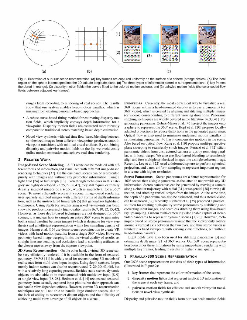
Fig. 2. Illustration of our 360° scene representation: (a) Key frames are captured uniformly on the surface of a sphere (orange circles). (b) The localregion on the sphere is remapped into the 2D latitude-longitude plane. (c) The three types of information stored in our representation: (1) key frames(bordered in orange), (2) disparity motion fields (the curves fitted to the colored motion vectors), and (3) pairwise motion fields (the color-coded flowfields between adjacent key frames).
ranges from recording to rendering of real scenes. The resultsshow that our system enables head-motion parallax, which ismissing from existing panorama-based approaches.
• A robust curve-based fitting method for estimating disparity mo-tion fields, which implicitly conveys depth information for aviewpoint. Disparity motion fields are estimated more robustlycompared to traditional stereo matching-based depth estimation.
• Novel-view synthesis with real-time flow-based blending betweensynthesized images from different viewpoints produces smoothviewpoint transitions with minimal visual artifacts. By combiningdisparity and pairwise motion fields on the fly, we avoid costlyonline motion estimation and achieve real-time rendering.
2 RELATED WORK
Image-Based Scene Modeling A 3D scene can be modeled with dif-ferent forms of information,and visualized with different image-basedrendering techniques [37]. On the one hand, scenes can be representedpurely with images and without any geometric information, using alight field [24] or lumigraph [13]. Even though techniques in this cate-gory are highly developed [23,25,27,36,47], they still require extremelydensely sampled images of a scene, which is impractical for a 360°scene. To more efficiently represent a scene, image-based renderinguses sparsely sampled images with different forms of depth informa-tion, such as the unstructured lumigraph [5] that generalizes light-fieldtechniques. Using depth for synthesizing novel viewpoints has beenshown to produce increasingly high-quality results [6, 7, 10, 12, 15, 42].However, as these depth-based techniques are not designed for 360°scenes, it is unclear how to sample an entire 360° scene to guaranteeboth a small baseline between images (which is desirable for view syn-thesis) and an efficient representation with a low sampling density ofimages. Huang et al. [16] use dense scene reconstruction to create VRvideos with head-motion parallax from a single 360° video. However,geometry-based image warping limits the visual quality of results, asstraight lines are bending, and occlusions lead to stretching artifacts, asthe viewer moves away from the capture viewpoint.3D Scene Reconstruction On the other hand, a virtual 3D scene canbe very efficiently rendered if it is available in the form of texturedgeometry. PMVS [11] is widely used for reconstructing 3D models ofreal scenes from multi-view input images. Using depth sensors, larger,mostly indoor, scenes can also be reconstructed [2, 29, 30, 43, 46], butwith a relatively long capturing process. Besides static scenes, dynamicobjects are also able to be reconstructed with multiview input [8, 9]or single-view input [18, 28]. Hedman et al. [14] reconstruct texturedgeometry from casually captured input photos, but their approach can-not handle view-dependent effects. However, current 3D reconstructiontechniques are still not able to handle large outdoor scenes, due tothe lack of ability to reconstruct distant objects and the difficulty ofachieving multi-view coverage of all objects in a scene.
Panoramas Currently, the most convenient way to visualize a real360° scene within a head-mounted display is to use a panorama (or360° video), which is created by aligning and stitching multiple images(or videos) corresponding to different viewing directions. Panoramastitching techniques are widely covered in the literature [4, 33, 41]. Forgenerating panoramas, Zelnik-Manor et al. [45] project the images ontoa sphere to represent the 360° scene. Kopf et al. [20] propose locally-adapted projections to reduce distortions in the generated panoramas.Optical flow is also used to minimize undesired motion parallax insynthesizing panoramas [40], as it compensates motions in the scene.Also based on optical flow, Kang et al. [19] propose multi-perspectiveplane sweeping to seamlessly stitch images. Perazzi et al. [32] stitchpanoramic videos from unstructured camera arrays by removing paral-lax with local warps. We also use flow-based blending to seamlesslyalign and fuse multiple synthesized images into a single coherent image.Recently, Lee et al. [22] used a deformed sphere to perform sphericalprojection, and a non-uniform sampling to represent important regionsin a scene with higher resolution.Stereo Panoramas Stereo panoramas are a better representation for360° scenes than a single panorama, as the latter do not provide any 3Dinformation. Stereo panoramas can be generated by moving a cameraalong a circular trajectory with radial [31] or tangential [38] viewing di-rection, and stitching vertical stripes from the images. At the same time,the depth of a panorama can also be estimated, and thus stereo visioncan be achieved [39]. Recently, Richardt et al. [35] proposed a practicalsolution for creating high-quality stereo panoramas by stabilizing andcorrecting input images, and seamless stitching them using flow-basedray upsampling. Custom multi-camera rigs also enable capture of stereovideo panorama to represent dynamic scenes [1, 26]. However, tech-niques based on stereo panoramas assume that the viewer only rotatesaround a vertical axis between the two eyes, and thus stereo vision islimited to a fixed viewpoint with varying view directions, but withouthead-motion parallax.
Light fields have also been used for stitching panoramas [3] andestimating depth maps [21] of 360° scenes. Our 360° scene representa-tion overcomes these limitations by using image-based rendering withmultiple key frames, leading to results of higher visual quality.
3 PARALLAX360 SCENE REPRESENTATION
Our 360° scene representation consists of three types of information(illustrated in Figure 2):
1. key frames that represent the color information of the scene,
2. disparity motion fields that represent implicit 3D information ofthe scene at each key frame, and
3. pairwise motion fields for efficient and smooth viewpoint transi-tions in novel-view synthesis.
Disparity and pairwise motion fields form our two-scale motion fields.
(a) (b)
𝐼𝑘
(c)
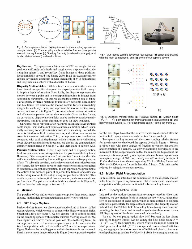
Fig. 3. Our capture scheme: (a) Key frames on the sampling sphere, asorange points. (b) The sampling circle of relative frames (blue points)around one key frame. (c) One key frame Ik (bordered in orange), andits six relative frames (bordered in blue).
Key Frames To capture a complete scene in 360°, we sample discretepositions uniformly in latitude and longitude on a sphere (called the‘sampling sphere’), and record key frame images at these positionslooking radially outward (see Figure 2a,b). In all our experiments, wecapture key frames at uniform angular increments of 5° in both latitudeand longitude on a sphere with a diameter of 1.25 m.
Disparity Motion Fields While a key frame describes the visual in-formation of one specific viewpoint, the disparity motion field conveysits implicit depth information. Specifically, the disparity represents themotion between a point and its corresponding points in images fromsurrounding viewpoints. For this, we extend the common case of binoc-ular disparity in stereo matching to multiple viewpoints surroundingone key frame. We estimate the motion vectors for six surroundingimages for each key frame, and represent the motion vectors usingcurves, as illustrated in Figure 2c, for more robust motion estimationand efficient computation during view synthesis. Given the key frames,the curve-based disparity motion fields can be used to synthesize nearbyviewpoints, similar to depth information used for view synthesis.
Our curve-based representation has three advantages over explicitdepth maps. First, it does not require camera calibration which is nor-mally necessary for depth estimation with stereo matching. Second, thecurve is fitted to multiple motion vectors, and is thus more robust toerrors in the motion estimation. Third, our representation is redundantcompared with explicit depth maps, which is useful for synthesizingnovel viewpoints in different directions. We discuss the computation ofdisparity motion fields in Section 4.2, and their usage in Section 4.3.1.
Pairwise Motion Fields Given a key frame and its disparity motionfield, we can render novel viewpoints near the position of the key frame.However, if the viewpoint moves from one key frame to another, thesudden switch between key frames will generate noticeable popping ar-tifacts. To solve this problem, and achieve a smooth transition betweenkey frames, the flow fields between their respective results are requiredto synthesize a smooth interpolation. In our approach, we precomputethe optical flow between pairs of adjacent key frames, and calculatethe blending motion fields online using simple flow arithmetic. Thisavoids expensive online optical flow estimation, and ensures real-timeperformance. The pairwise motion fields are visualized in Figure 2c,and we describe their usage in Section 4.3.
4 METHOD
The pipeline of our end-to-end system comprises three steps: imagecapture, motion field precomputation and novel-view synthesis.
4.1 360° Image CaptureBesides the key frames, we also capture another kind of frames, calledrelative frames, which we use to compute the disparity motion fields.Specifically, for a key frame Ik, we first capture it at its defined positionon the sampling sphere with radially outward viewing direction. Wethen capture six relative frames at positions close to the key frame. Inour approach, relative frames are captured on a circle centered at thekey frame position, with a fixed radius of 25 mm in our experiments.Figure 3b shows the sampling pattern of relative frames in our approach.Finally, these seven images (shown in Figure 3c) are grouped together
Stepper motors
Camera
Robotic arm
Fig. 4. Our robotic capture device for real scenes: (a) Schematic drawingwith the main components, and (b) photo of our capture device.
(a) (b) (c)
……
……
{𝐶𝑃|𝑃 ∈ 𝐼𝑘}
𝑓1
𝑓2
𝑓6
Fig. 5. Disparity motion fields: (a) Relative frames. (b) Motion fields{ f 1, f 2, . . . , f 6} between the key frame and each relative frame. (c) Dis-parity motion curves {CP} for each image patch P in the key frame Ik.
for the next steps. Note that the relative frames are discarded after themotion field computation, and only the key frames are kept.
To capture the key frames and the corresponding relative framesfor a real scene, we developed the capture device in Figure 4. We usea robotic arm with three degrees-of-freedom to control the positionand orientation of a camera. We convert sampling coordinates to themovement of the stepper motors, so that the camera can be placed at thecamera position required by our capture scheme. In our experiments,we capture a range of 360° horizontally and 40° vertically in steps of5°. Our device captures the corresponding 72×8=576 key frames and576×6=3,456 relative frames in less than 2 hours. This time can bereduced by using faster stepper motors.
4.2 Motion Field PrecomputationIn this section, we introduce the computation of the disparity motionfields from the captured key frames and relative frames, and then discusscomputation of the pairwise motion fields between key frames.
4.2.1 Disparity Motion FieldsInspired by the motion compensation techniques used in video com-pression, we use motion fields to synthesize new views, rather thanrely on an estimate of scene depth, which is more difficult to estimateaccurately, particularly for large outdoor scenes. The disparity motionfield defines the 2D flow field from a key frame to any viewpoint sur-rounding the key frame, and is used to synthesize these novel views.All disparity motion fields are computed independently.
We start by computing optical flow [44] between the key frameand all its relative frames. Let us denote the flow fields using F ={ f 1, f 2, . . . , f 6} (see Figure 5b), where f i(p) is the motion vector forpixel p in the flow field f i. For storage and computational efficien-cy, we aggregate the motion vectors of individual pixels p into non-overlapping image patches P of size 8×8 pixels by averaging them. As
(b)
𝑟2
𝑟1
𝑟6
𝑟5
𝑟4
𝑟3
𝑟𝑡
(a)
𝑣𝑃1
𝑣𝑃2
𝑣𝑃3
𝑣𝑃4
𝑣𝑃5
𝑣𝑃6
𝑣𝑃𝑡
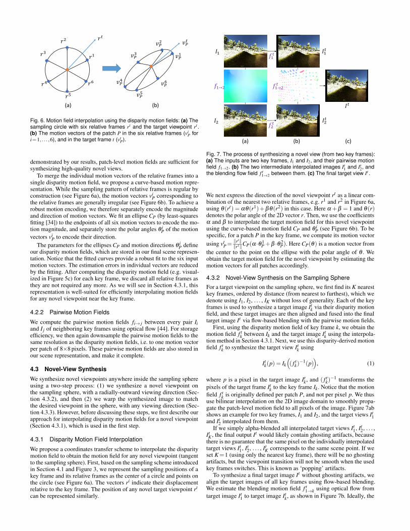
Fig. 6. Motion field interpolation using the disparity motion fields: (a) Thesampling circle with six relative frames ri and the target viewpoint rt .(b) The motion vectors of the patch P in the six relative frames (vi
P fori=1, . . . ,6), and in the target frame t (vt
P).
demonstrated by our results, patch-level motion fields are sufficient forsynthesizing high-quality novel views.
To merge the individual motion vectors of the relative frames into asingle disparity motion field, we propose a curve-based motion repre-sentation. While the sampling pattern of relative frames is regular byconstruction (see Figure 6a), the motion vectors vi
P corresponding tothe relative frames are generally irregular (see Figure 6b). To achieve arobust motion encoding, we therefore separately encode the magnitudeand direction of motion vectors. We fit an ellipse CP (by least-squaresfitting [34]) to the endpoints of all six motion vectors to encode the mo-tion magnitude, and separately store the polar angles θ i
P of the motionvectors vi
P to encode their direction.The parameters for the ellipses CP and motion directions θ i
P defineour disparity motion fields, which are stored in our final scene represen-tation. Notice that the fitted curves provide a robust fit to the six inputmotion vectors. The estimation errors in individual vectors are reducedby the fitting. After computing the disparity motion field (e.g. visual-ized in Figure 5c) for each key frame, we discard all relative frames asthey are not required any more. As we will see in Section 4.3.1, thisrepresentation is well-suited for efficiently interpolating motion fieldsfor any novel viewpoint near the key frame.
4.2.2 Pairwise Motion Fields
We compute the pairwise motion fields fi→ j between every pair Iiand I j of neighboring key frames using optical flow [44]. For storageefficiency, we then again downsample the pairwise motion fields to thesame resolution as the disparity motion fields, i.e. to one motion vectorper patch of 8×8 pixels. These pairwise motion fields are also stored inour scene representation, and make it complete.
4.3 Novel-View Synthesis
We synthesize novel viewpoints anywhere inside the sampling sphereusing a two-step process: (1) we synthesize a novel viewpoint onthe sampling sphere, with a radially-outward viewing direction (Sec-tion 4.3.2), and then (2) we warp the synthesized image to matchthe desired viewpoint in the sphere, with any viewing direction (Sec-tion 4.3.3). However, before discussing these steps, we first describe ourapproach for interpolating disparity motion fields for a novel viewpoint(Section 4.3.1), which is used in the first step.
4.3.1 Disparity Motion Field Interpolation
We propose a coordinates transfer scheme to interpolate the disparitymotion field to obtain the motion field for any novel viewpoint (tangentto the sampling sphere). First, based on the sampling scheme introducedin Section 4.1 and Figure 3, we represent the sampling positions of akey frame and its relative frames as the center of a circle and points onthe circle (see Figure 6a). The vectors ri indicate their displacementrelative to the key frame. The position of any novel target viewpoint rt
can be represented similarly.
𝐼1
𝐼2
𝑓1→2
𝐼1𝑡
𝐼2𝑡
𝑓1→2𝑡
𝐼𝑡
(a) (b) (c)
𝑓1𝑡
𝑓2𝑡
Fig. 7. The process of synthesizing a novel view (from two key frames):(a) The inputs are two key frames, I1 and I2, and their pairwise motionfield f1→2. (b) The two intermediate interpolated images It
1 and It2, and
the blending flow field f t1→2 between them. (c) The final target view It .
We next express the direction of the novel viewpoint rt as a linear com-bination of the nearest two relative frames, e.g. r1 and r2 in Figure 6a,using θ(rt) = αθ(r1)+βθ(r2) in this case. Here α +β = 1 and θ(r)denotes the polar angle of the 2D vector r. Then, we use the coefficientsα and β to interpolate the target motion field for this novel viewpointusing the curve-based motion field CP and θ i
P (see Figure 6b). To bespecific, for a patch P in the key frame, we compute its motion vectorusing vt
P=‖rt‖‖r1‖CP(α ·θ 1
P +β ·θ 2P). Here CP(θ) is a motion vector from
the center to the point on the ellipse with the polar angle of θ . Weobtain the target motion field for the novel viewpoint by estimating themotion vectors for all patches accordingly.
4.3.2 Novel-View Synthesis on the Sampling SphereFor a target viewpoint on the sampling sphere, we first find its K nearestkey frames, ordered by distance (from nearest to furthest), which wedenote using I1, I2, . . . , IK without loss of generality. Each of the keyframes is used to synthesize a target image It
k via their disparity motionfield, and these target images are then aligned and fused into the finaltarget image It via flow-based blending with the pairwise motion fields.
First, using the disparity motion field of key frame k, we obtain themotion field f t
k between Ik and the target image Itk using the interpola-
tion method in Section 4.3.1. Next, we use this disparity-derived motionfield f t
k to synthesize the target view Itk using
Itk(p) = Ik
(( f t
k)−1(p)
), (1)
where p is a pixel in the target image Itk, and ( f t
k)−1 transforms the
pixels of the target frame Itk to the key frame Ik. Notice that the motion
field f tk is originally defined per patch P, and not per pixel p. We thus
use bilinear interpolation on the 2D image domain to smoothly propa-gate the patch-level motion field to all pixels of the image. Figure 7abshows an example for two key frames, I1 and I2, and the target views It
1and It
2 interpolated from them.If we simply alpha-blended all interpolated target views It
1, It2, . . . ,
ItK , the final output It would likely contain ghosting artifacts, because
there is no guarantee that the same pixel on the individually interpolatedtarget views It
1, It2, . . . , It
K corresponds to the same scene point. If weset K=1 (using only the nearest key frame), there will be no ghostingartifacts, but the viewpoint transition will not be smooth when the usedkey frames switches. This is known as ‘popping’ artifacts.
To synthesize a final target image It without ghosting artifacts, wealign the target images of all key frames using flow-based blending.We estimate the blending motion field f t
1→k using optical flow fromtarget image It
1 to target image Itk, as shown in Figure 7b. Ideally, the
Stereo Panorama Our Method
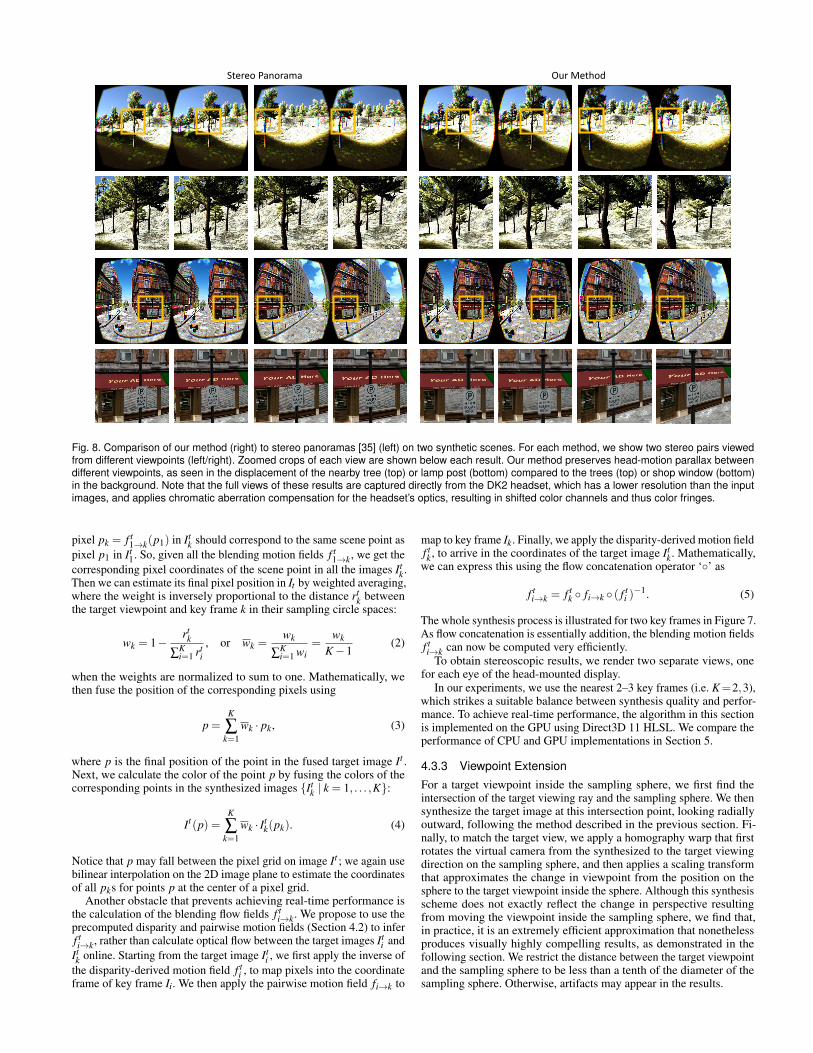
Fig. 8. Comparison of our method (right) to stereo panoramas [35] (left) on two synthetic scenes. For each method, we show two stereo pairs viewedfrom different viewpoints (left/right). Zoomed crops of each view are shown below each result. Our method preserves head-motion parallax betweendifferent viewpoints, as seen in the displacement of the nearby tree (top) or lamp post (bottom) compared to the trees (top) or shop window (bottom)in the background. Note that the full views of these results are captured directly from the DK2 headset, which has a lower resolution than the inputimages, and applies chromatic aberration compensation for the headset’s optics, resulting in shifted color channels and thus color fringes.
pixel pk = f t1→k(p1) in It
k should correspond to the same scene point aspixel p1 in It
1. So, given all the blending motion fields f t1→k, we get the
corresponding pixel coordinates of the scene point in all the images Itk.
Then we can estimate its final pixel position in It by weighted averaging,where the weight is inversely proportional to the distance rt
k betweenthe target viewpoint and key frame k in their sampling circle spaces:
wk = 1−rt
k
∑Ki=1 rt
i, or wk =
wk
∑Ki=1 wi
=wk
K−1(2)
when the weights are normalized to sum to one. Mathematically, wethen fuse the position of the corresponding pixels using
p =K
∑k=1
wk · pk, (3)
where p is the final position of the point in the fused target image It .Next, we calculate the color of the point p by fusing the colors of thecorresponding points in the synthesized images {It
k | k = 1, . . . ,K}:
It(p) =K
∑k=1
wk · Itk(pk). (4)
Notice that p may fall between the pixel grid on image It ; we again usebilinear interpolation on the 2D image plane to estimate the coordinatesof all pks for points p at the center of a pixel grid.
Another obstacle that prevents achieving real-time performance isthe calculation of the blending flow fields f t
i→k. We propose to use theprecomputed disparity and pairwise motion fields (Section 4.2) to inferf ti→k, rather than calculate optical flow between the target images It
i andItk online. Starting from the target image It
i , we first apply the inverse ofthe disparity-derived motion field f t
i , to map pixels into the coordinateframe of key frame Ii. We then apply the pairwise motion field fi→k to
map to key frame Ik. Finally, we apply the disparity-derived motion fieldf tk , to arrive in the coordinates of the target image It
k. Mathematically,we can express this using the flow concatenation operator ‘◦’ as
f ti→k = f t
k ◦ fi→k ◦ ( f ti )−1. (5)
The whole synthesis process is illustrated for two key frames in Figure 7.As flow concatenation is essentially addition, the blending motion fieldsf ti→k can now be computed very efficiently.
To obtain stereoscopic results, we render two separate views, onefor each eye of the head-mounted display.
In our experiments, we use the nearest 2–3 key frames (i.e. K=2,3),which strikes a suitable balance between synthesis quality and perfor-mance. To achieve real-time performance, the algorithm in this sectionis implemented on the GPU using Direct3D 11 HLSL. We compare theperformance of CPU and GPU implementations in Section 5.
4.3.3 Viewpoint Extension
For a target viewpoint inside the sampling sphere, we first find theintersection of the target viewing ray and the sampling sphere. We thensynthesize the target image at this intersection point, looking radiallyoutward, following the method described in the previous section. Fi-nally, to match the target view, we apply a homography warp that firstrotates the virtual camera from the synthesized to the target viewingdirection on the sampling sphere, and then applies a scaling transformthat approximates the change in viewpoint from the position on thesphere to the target viewpoint inside the sphere. Although this synthesisscheme does not exactly reflect the change in perspective resultingfrom moving the viewpoint inside the sampling sphere, we find that,in practice, it is an extremely efficient approximation that nonethelessproduces visually highly compelling results, as demonstrated in thefollowing section. We restrict the distance between the target viewpointand the sampling sphere to be less than a tenth of the diameter of thesampling sphere. Otherwise, artifacts may appear in the results.
Stereo Panorama Our Method
Note flower behind vase
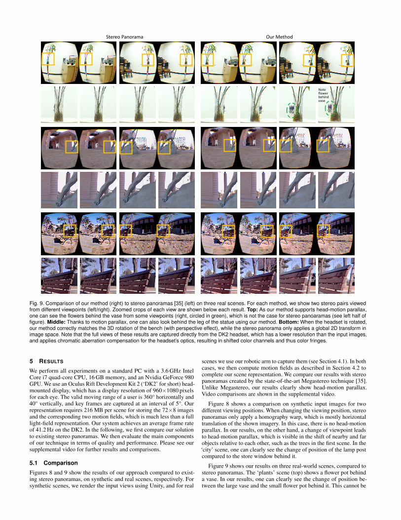
Fig. 9. Comparison of our method (right) to stereo panoramas [35] (left) on three real scenes. For each method, we show two stereo pairs viewedfrom different viewpoints (left/right). Zoomed crops of each view are shown below each result. Top: As our method supports head-motion parallax,one can see the flowers behind the vase from some viewpoints (right, circled in green), which is not the case for stereo panoaramas (see left half offigure). Middle: Thanks to motion parallax, one can also look behind the leg of the statue using our method. Bottom: When the headset is rotated,our method correctly matches the 3D rotation of the bench (with perspective effect), while the stereo panorama only applies a global 2D transform inimage space. Note that the full views of these results are captured directly from the DK2 headset, which has a lower resolution than the input images,and applies chromatic aberration compensation for the headset’s optics, resulting in shifted color channels and thus color fringes.
5 RESULTS
We perform all experiments on a standard PC with a 3.6 GHz IntelCore i7 quad-core CPU, 16 GB memory, and an Nvidia GeForce 980GPU. We use an Oculus Rift Development Kit 2 (‘DK2’ for short) head-mounted display, which has a display resolution of 960×1080 pixelsfor each eye. The valid moving range of a user is 360° horizontally and40° vertically, and key frames are captured at an interval of 5°. Ourrepresentation requires 216 MB per scene for storing the 72×8 imagesand the corresponding two motion fields, which is much less than a fulllight-field representation. Our system achieves an average frame rateof 41.2 Hz on the DK2. In the following, we first compare our solutionto existing stereo panoramas. We then evaluate the main componentsof our technique in terms of quality and performance. Please see oursupplemental video for further results and comparisons.
5.1 Comparison
Figures 8 and 9 show the results of our approach compared to exist-ing stereo panoramas, on synthetic and real scenes, respectively. Forsynthetic scenes, we render the input views using Unity, and for real
scenes we use our robotic arm to capture them (see Section 4.1). In bothcases, we then compute motion fields as described in Section 4.2 tocomplete our scene representation. We compare our results with stereopanoramas created by the state-of-the-art Megastereo technique [35].Unlike Megastereo, our results clearly show head-motion parallax.Video comparisons are shown in the supplemental video.
Figure 8 shows a comparison on synthetic input images for twodifferent viewing positions. When changing the viewing position, stereopanoramas only apply a homography warp, which is mostly horizontaltranslation of the shown imagery. In this case, there is no head-motionparallax. In our results, on the other hand, a change of viewpoint leadsto head-motion parallax, which is visible in the shift of nearby and farobjects relative to each other, such as the trees in the first scene. In the‘city’ scene, one can clearly see the change of position of the lamp postcompared to the store window behind it.
Figure 9 shows our results on three real-world scenes, compared tostereo panoramas. The ‘plants’ scene (top) shows a flower pot behinda vase. In our results, one can clearly see the change of position be-tween the large vase and the small flower pot behind it. This cannot be
𝑡 𝑡 + 1 𝑡 𝑡 + 1 𝑡 𝑡 + 1
Nearest Key Frame (NKF) Alpha Blending (AB) Flow Based Blending (FBB)
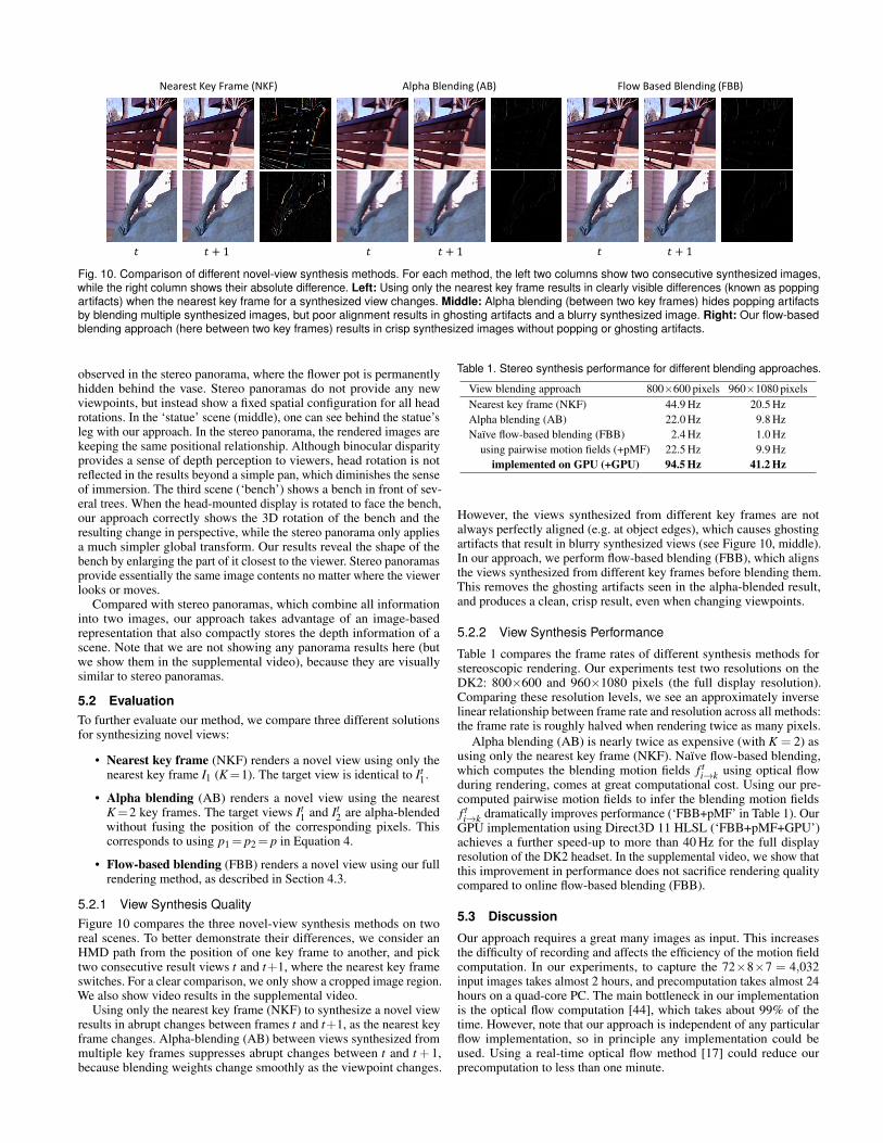
Fig. 10. Comparison of different novel-view synthesis methods. For each method, the left two columns show two consecutive synthesized images,while the right column shows their absolute difference. Left: Using only the nearest key frame results in clearly visible differences (known as poppingartifacts) when the nearest key frame for a synthesized view changes. Middle: Alpha blending (between two key frames) hides popping artifactsby blending multiple synthesized images, but poor alignment results in ghosting artifacts and a blurry synthesized image. Right: Our flow-basedblending approach (here between two key frames) results in crisp synthesized images without popping or ghosting artifacts.
observed in the stereo panorama, where the flower pot is permanentlyhidden behind the vase. Stereo panoramas do not provide any newviewpoints, but instead show a fixed spatial configuration for all headrotations. In the ‘statue’ scene (middle), one can see behind the statue’sleg with our approach. In the stereo panorama, the rendered images arekeeping the same positional relationship. Although binocular disparityprovides a sense of depth perception to viewers, head rotation is notreflected in the results beyond a simple pan, which diminishes the senseof immersion. The third scene (‘bench’) shows a bench in front of sev-eral trees. When the head-mounted display is rotated to face the bench,our approach correctly shows the 3D rotation of the bench and theresulting change in perspective, while the stereo panorama only appliesa much simpler global transform. Our results reveal the shape of thebench by enlarging the part of it closest to the viewer. Stereo panoramasprovide essentially the same image contents no matter where the viewerlooks or moves.
Compared with stereo panoramas, which combine all informationinto two images, our approach takes advantage of an image-basedrepresentation that also compactly stores the depth information of ascene. Note that we are not showing any panorama results here (butwe show them in the supplemental video), because they are visuallysimilar to stereo panoramas.
5.2 EvaluationTo further evaluate our method, we compare three different solutionsfor synthesizing novel views:
• Nearest key frame (NKF) renders a novel view using only thenearest key frame I1 (K=1). The target view is identical to It
1.
• Alpha blending (AB) renders a novel view using the nearestK=2 key frames. The target views It
1 and It2 are alpha-blended
without fusing the position of the corresponding pixels. Thiscorresponds to using p1= p2= p in Equation 4.
• Flow-based blending (FBB) renders a novel view using our fullrendering method, as described in Section 4.3.
5.2.1 View Synthesis QualityFigure 10 compares the three novel-view synthesis methods on tworeal scenes. To better demonstrate their differences, we consider anHMD path from the position of one key frame to another, and picktwo consecutive result views t and t+1, where the nearest key frameswitches. For a clear comparison, we only show a cropped image region.We also show video results in the supplemental video.
Using only the nearest key frame (NKF) to synthesize a novel viewresults in abrupt changes between frames t and t+1, as the nearest keyframe changes. Alpha-blending (AB) between views synthesized frommultiple key frames suppresses abrupt changes between t and t + 1,because blending weights change smoothly as the viewpoint changes.
Table 1. Stereo synthesis performance for different blending approaches.
View blending approach 800×600 pixels 960×1080 pixelsNearest key frame (NKF) 44.9 Hz 20.5 HzAlpha blending (AB) 22.0 Hz 9.8 HzNaïve flow-based blending (FBB) 2.4 Hz 1.0 Hz
using pairwise motion fields (+pMF) 22.5 Hz 9.9 Hzimplemented on GPU (+GPU) 94.5 Hz 41.2 Hz
However, the views synthesized from different key frames are notalways perfectly aligned (e.g. at object edges), which causes ghostingartifacts that result in blurry synthesized views (see Figure 10, middle).In our approach, we perform flow-based blending (FBB), which alignsthe views synthesized from different key frames before blending them.This removes the ghosting artifacts seen in the alpha-blended result,and produces a clean, crisp result, even when changing viewpoints.
5.2.2 View Synthesis Performance
Table 1 compares the frame rates of different synthesis methods forstereoscopic rendering. Our experiments test two resolutions on theDK2: 800×600 and 960×1080 pixels (the full display resolution).Comparing these resolution levels, we see an approximately inverselinear relationship between frame rate and resolution across all methods:the frame rate is roughly halved when rendering twice as many pixels.
Alpha blending (AB) is nearly twice as expensive (with K = 2) asusing only the nearest key frame (NKF). Naïve flow-based blending,which computes the blending motion fields f t
i→k using optical flowduring rendering, comes at great computational cost. Using our pre-computed pairwise motion fields to infer the blending motion fieldsf ti→k dramatically improves performance (‘FBB+pMF’ in Table 1). Our
GPU implementation using Direct3D 11 HLSL (‘FBB+pMF+GPU’)achieves a further speed-up to more than 40 Hz for the full displayresolution of the DK2 headset. In the supplemental video, we show thatthis improvement in performance does not sacrifice rendering qualitycompared to online flow-based blending (FBB).
5.3 Discussion
Our approach requires a great many images as input. This increasesthe difficulty of recording and affects the efficiency of the motion fieldcomputation. In our experiments, to capture the 72×8×7 = 4,032input images takes almost 2 hours, and precomputation takes almost 24hours on a quad-core PC. The main bottleneck in our implementationis the optical flow computation [44], which takes about 99% of thetime. However, note that our approach is independent of any particularflow implementation, so in principle any implementation could beused. Using a real-time optical flow method [17] could reduce ourprecomputation to less than one minute.
𝑡 𝑡 + 1 𝑡 + 2 𝑡 + 3
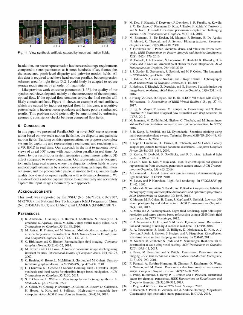
Fig. 11. View-synthesis artifacts caused by incorrect motion fields.
In addition, our scene representation has increased storage requirementscompared to stereo panoramas, as it stores hundreds of key frames plusthe associated patch-level disparity and pairwise motion fields. Allthis data is required to achieve head-motion parallax, but compressionschemes used for light fields [5, 24] could likely be adapted to reducestorage requirements by an order of magnitude.
Like previous work on stereo panoramas [1, 35], the quality of oursynthesized views depends mainly on the correctness of the computedoptical flow. If the optical flow contains errors, the final results willlikely contain artifacts. Figure 11 shows an example of such artifacts,which are caused by incorrect optical flow. In this case, a repetitivepattern leads to incorrect correspondence and hence poorly synthesizedresults. This problem could potentially be ameliorated by enforcinggeometric consistency checks between computed flow fields.
6 CONCLUSION
In this paper, we presented Parallax360 – a novel 360° scene represen-tation based on two-scale motion fields, i.e. the disparity and pairwisemotion fields. Building on this representation, we propose a completesystem for capturing and representing a real scene, and rendering it ina VR HMD in real time. Our approach is the first to generate novelviews of a real 360° scene with head-motion parallax in real time. Asshown by our results, our system generates a much more realistic 3Deffect compared to stereo panoramas. Our representation is designedto handle large real scenes, where the disparity motion fields achieveimplicit depth estimation by a robust curve-fitting technique that filtersout noise, and the precomputed pairwise motion fields guarantee high-quality flow-based viewpoint synthesis with real-time performance. Wealso developed a robotic capture device to automatically and accuratelycapture the input images required by our approach.
ACKNOWLEDGMENTS
This work was supported by the NSFC (No. 61671268, 61672307,61727808), the National Key Technologies R&D Program of China(No. 2015BAF23B03) and EPSRC grant CAMERA (EP/M023281/1).
REFERENCES
[1] R. Anderson, D. Gallup, J. T. Barron, J. Kontkanen, N. Snavely, C. H-ernández, S. Agarwal, and S. M. Seitz. Jump: virtual reality video. ACMTransactions on Graphics, 35(6):198, 2016.
[2] M. Arikan, R. Preiner, and M. Wimmer. Multi-depth-map raytracing forefficient large-scene reconstruction. IEEE Transactions on Visualizationand Computer Graphics, 22(2):1127–1137, 2016.
[3] C. Birklbauer and O. Bimber. Panorama light-field imaging. ComputerGraphics Forum, 33(2):43–52, 2014.
[4] M. Brown and D. G. Lowe. Automatic panoramic image stitching usinginvariant features. International Journal of Computer Vision, 74(1):59–73,2007.
[5] C. Buehler, M. Bosse, L. McMillan, S. Gortler, and M. Cohen. Unstruc-tured lumigraph rendering. In SIGGRAPH, pp. 425–432, 2001.
[6] G. Chaurasia, S. Duchene, O. Sorkine-Hornung, and G. Drettakis. Depthsynthesis and local warps for plausible image-based navigation. ACMTransactions on Graphics, 32(3):30, 2013.
[7] S. E. Chen and L. Williams. View interpolation for image synthesis. InSIGGRAPH, pp. 279–288, 1993.
[8] A. Collet, M. Chuang, P. Sweeney, D. Gillett, D. Evseev, D. Calabrese,H. Hoppe, A. Kirk, and S. Sullivan. High-quality streamable free-viewpoint video. ACM Transactions on Graphics, 34(4):69, 2015.
[9] M. Dou, S. Khamis, Y. Degtyarev, P. Davidson, S. R. Fanello, A. Kowdle,S. O. Escolano, C. Rhemann, D. Kim, J. Taylor, P. Kohli, V. Tankovich,and S. Izadi. Fusion4D: real-time performance capture of challengingscenes. ACM Transactions on Graphics, 35(4):114, 2016.
[10] M. Eisemann, B. De Decker, M. Magnor, P. Bekaert, E. De Aguiar,N. Ahmed, C. Theobalt, and A. Sellent. Floating textures. ComputerGraphics Forum, 27(2):409–418, 2008.
[11] Y. Furukawa and J. Ponce. Accurate, dense, and robust multiview stere-opsis. IEEE Transactions on Pattern Analysis and Machine Intelligence,32(8):1362–1376, 2010.
[12] M. Goesele, J. Ackermann, S. Fuhrmann, C. Haubold, R. Klowsky, D. S-teedly, and R. Szeliski. Ambient point clouds for view interpolation. ACMTransactions on Graphics, 29(4):95, 2010.
[13] S. J. Gortler, R. Grzeszczuk, R. Szeliski, and M. F. Cohen. The lumigraph.In SIGGRAPH, pp. 43–54, 1996.
[14] P. Hedman, S. Alsisan, R. Szeliski, and J. Kopf. Casual 3D photography.ACM Transactions on Graphics, 36(6):234:1–15, 2017.
[15] P. Hedman, T. Ritschel, G. Drettakis, and G. Brostow. Scalable inside-outimage-based rendering. ACM Transactions on Graphics, 35(6):231:1–11,2016.
[16] J. Huang, Z. Chen, D. Ceylan, and H. Jin. 6-DOF VR videos with a single360-camera. In Proceedings of IEEE Virtual Reality (VR), pp. 37–44,2017.
[17] E. Ilg, N. Mayer, T. Saikia, M. Keuper, A. Dosovitskiy, and T. Brox.FlowNet 2.0: Evolution of optical flow estimation with deep networks. InCVPR, 2017.
[18] M. Innmann, M. Zollhöfer, M. Nießner, C. Theobalt, and M. Stamminger.VolumeDeform: Real-time volumetric non-rigid reconstruction. In ECCV,2016.
[19] S. B. Kang, R. Szeliski, and M. Uyttendaele. Seamless stitching usingmulti-perspective plane sweep. Technical Report MSR-TR-2004-48, Mi-crosoft Research, 2004.
[20] J. Kopf, D. Lischinski, O. Deussen, D. Cohen-Or, and M. Cohen. Locallyadapted projections to reduce panorama distortions. Computer GraphicsForum, 28(4):1083–1089, 2009.
[21] B. Krolla, M. Diebold, B. Goldlücke, and D. Stricker. Spherical lightfields. In BMVC, 2014.
[22] J. Lee, B. Kim, K. Kim, Y. Kim, and J. Noh. Rich360: optimized sphericalrepresentation from structured panoramic camera arrays. ACM Transac-tions on Graphics, 35(4):63, 2016.
[23] A. Levin and F. Durand. Linear view synthesis using a dimensionality gaplight field prior. In CVPR, 2010.
[24] M. Levoy and P. Hanrahan. Light field rendering. In SIGGRAPH, pp.31–42, 1996.
[25] K. Marwah, G. Wetzstein, Y. Bando, and R. Raskar. Compressive light fieldphotography using overcomplete dictionaries and optimized projections.ACM Transactions on Graphics, 32(4):46, 2013.
[26] K. Matzen, M. F. Cohen, B. Evans, J. Kopf, and R. Szeliski. Low-cost 360stereo photography and video capture. ACM Transactions on Graphics,36(4):148, 2017.
[27] K. Mitra and A. Veeraraghavan. Light field denoising, light field super-resolution and stereo camera based refocussing using a GMM light fieldpatch prior. In CVPR Workshops, 2012.
[28] R. A. Newcombe, D. Fox, and S. M. Seitz. DynamicFusion: Reconstruc-tion and tracking of non-rigid scenes in real-time. In CVPR, 2015.
[29] R. A. Newcombe, S. Izadi, O. Hilliges, D. Molyneaux, D. Kim, A. J.Davison, P. Kohi, J. Shotton, S. Hodges, and A. Fitzgibbon. KinectFusion:Real-time dense surface mapping and tracking. In ISMAR, 2011.
[30] M. Nießner, M. Zollhöfer, S. Izadi, and M. Stamminger. Real-time 3D re-construction at scale using voxel hashing. ACM Transactions on Graphics,32(6):169:1–11, 2013.
[31] S. Peleg, M. Ben-Ezra, and Y. Pritch. Omnistereo: Panoramic stereoimaging. IEEE Transactions on Pattern Analysis and Machine Intelligence,23(3):279–290, 2001.
[32] F. Perazzi, A. Sorkine-Hornung, H. Zimmer, P. Kaufmann, O. Wang,S. Watson, and M. Gross. Panoramic video from unstructured cameraarrays. Computer Graphics Forum, 34(2):57–68, 2015.
[33] S. Philip, B. Summa, J. Tierny, P.-T. Bremer, and V. Pascucci. Distributedseams for gigapixel panoramas. IEEE Transactions on Visualization andComputer Graphics, 21(3):350–362, 2015.
[34] L. Piegl and W. Tiller. The NURBS book. Springer, 2012.[35] C. Richardt, Y. Pritch, H. Zimmer, and A. Sorkine-Hornung. Megastereo:
Constructing high-resolution stereo panoramas. In CVPR, 2013.
[36] L. Shi, H. Hassanieh, A. Davis, D. Katabi, and F. Durand. Light fieldreconstruction using sparsity in the continuous Fourier domain. ACMTransactions on Graphics, 34(1):12, 2014.
[37] H.-Y. Shum, S.-C. Chan, and S. B. Kang. Image-Based Rendering.Springer, 2007.
[38] H.-Y. Shum and L.-W. He. Rendering with concentric mosaics. In SIG-GRAPH, pp. 299–306, 1999.
[39] H.-Y. Shum and R. Szeliski. Stereo reconstruction from multiperspectivepanoramas. In ICCV, 1999.
[40] H.-Y. Shum and R. Szeliski. Systems and experiment paper: Constructionof panoramic image mosaics with global and local alignment. InternationalJournal of Computer Vision, 36(2):101–130, 2000.
[41] R. Szeliski. Image alignment and stitching: A tutorial. Foundations andTrends® in Computer Graphics and Vision, 2(1):1–104, 2006.
[42] S. Wanner and B. Goldluecke. Variational light field analysis for disparityestimation and super-resolution. IEEE Transactions on Pattern Analysisand Machine Intelligence, 36(3):606–619, 2014.
[43] K. Xu, H. Huang, Y. Shi, H. Li, P. Long, J. Caichen, W. Sun, and B. Chen.Autoscanning for coupled scene reconstruction and proactive object analy-sis. ACM Transactions on Graphics, 34(6):177, 2015.
[44] L. Xu, J. Jia, and Y. Matsushita. Motion detail preserving optical flow esti-mation. IEEE Transactions on Pattern Analysis and Machine Intelligence,34(9):1744–1757, 2012.
[45] L. Zelnik-Manor, G. Peters, and P. Perona. Squaring the circle in panora-mas. In ICCV, 2005.
[46] Y. Zhang, W. Xu, Y. Tong, and K. Zhou. Online structure analysis forreal-time indoor scene reconstruction. ACM Transactions on Graphics,34(5):159, 2015.
[47] Z. Zhang, Y. Liu, and Q. Dai. Light field from micro-baseline image pair.In CVPR, 2015.