parallel fan powered variable air volume (vav)...
TRANSCRIPT
2010 McQuay International
Installation Manual IM 1102
Group: Controls
Part Number: IM 1102
Date: October 2010
Supersedes: New
Parallel Fan Powered Variable Air Volume (VAV) Terminal Boxes
Model(s): MQFVI5
Table of Contents
Table of Contents.................................................................................................................. 2 Revision History ................................................................................................................................... 3 Limited Warranty .................................................................................................................................. 3 Installation ............................................................................................................................. 4 Receiving Inspection............................................................................................................................. 4 Hanging/Installation Requirements....................................................................................................... 4 Connecting Ductwork ........................................................................................................................... 6 Minimum clearance For Access............................................................................................................ 6 Field Electrical Wiring.......................................................................................................................... 6
Fan Powered Air Terminal Units with Electric Heat ........................................................................ 7 Fan Powered Air Terminal Units with Hot Water Coils ................................................................... 7
Controls................................................................................................................................................. 8 Labeling ................................................................................................................................................ 8 Initial Start-up / Adjustment of Fan Flow Rate..................................................................................... 9 Troubleshooting.................................................................................................................. 10
Investigating Noise Complaints ...................................................................................................... 10 Discharge Noise .............................................................................................................................. 11 Radiated Noise ................................................................................................................................ 11 Controls........................................................................................................................................... 11 Electric Duct Heater........................................................................................................................ 11 Specific Electric Heat Troubleshooting Procedures:....................................................................... 12
2 IM 1102
Revision History
Manual Date
IM 1102 October 2010 Initial release
Limited Warranty Consult your local McQuay Representative for warranty details. Refer to Form 933-43285Y. To find your local McQuay Representative, go to www.mcquay.com.
Hazardous Information Messages
Familiarize yourself with the hazard identification messages used in this manual.
! DANGER
Dangers indicate a hazardous situation which will result in death or serious injury if not avoided.
! WARNING
Warnings indicate potentially hazardous situations, which can result in property damage, severe personal injury, or death if not avoided.
! CAUTION
Cautions indicate potentially hazardous situations, which can result in personal injury or equipment damage if not avoided.
Notice
Copyright © 2010 McQuay International, Minneapolis MN. All rights reserved throughout the world. McQuay International reserves the right to change any information contained herein without prior notice. The user is responsible for determining whether this software is appropriate for his or her application. ® ™ The following are trade names or registered trademarks of their respective companies: BACnet from the American Society of Heating, Refrigerating and Air-Conditioning Engineers, Inc.; Windows from Microsoft Corporation; McQuay and MicroTech from McQuay International.
IM 1102 3
Installation
Receiving Inspection Prior to removing the shipping material, visually inspect the packing materials. There should be a black plastic strip wrapped in the clear plastic shrink wrap. If this black plastic strip is missing, the shipment may have been repacked by the shipper and you should make note of this on the shipping documents and inform the delivering carrier. After unpacking the terminal, check it for shipping damage. If any shipping damage is found, report it immediately to the delivering carrier. Store units in a clean, dry location prior to installation. Units with controls are not recommended for use in ambient temperatures greater than 95°F. For protection of controls, do not store in ambient temperatures greater than 135°F. Caution: Do not use the flow sensor, connecting tubing, or damper shaft as a lift point. Damage to the flow sensor or controls may result.
Hanging/Installation Requirements The Fan Powered Air Terminal should be suspended from the building structure in a horizontal plane with the two bottom access panels facing downward. Do not obstruct the bottom access panels or control panel enclosure cover. At both ends of the air terminal unit, a three inch wide mounting lip provides easy installation of either trapeze type hangers or hanging straps. • Use the required mounting support method prescribed for the rectangular duct per the job specifications, or • Use hanging straps located at both ends of the fan powered unit (Figure 1), or • Use trapeze mounts located at both ends of the fan powered terminal unit (Figure 2), or • Fan powered air terminals may be suspended with optional hanging brackets and hanger rod. (See Figure 3) The Fan Powered Air Terminal is not suitable for outdoor use.
! CAUTION If equipped with pneumatic controls, the orientation of the terminal is critical. The pneumatic controls must be mounted right side up. The fan powered unit must be level within + or – 10 degrees of horizontal, both parallel to the air flow and at the right angle of air flow. The control side of the terminal is labeled with an arrow indicating UP. Unless otherwise noted, most analog and digital controls may be installed in any orientation. Check with the local McQuay representative for verification.
4 IM 1102
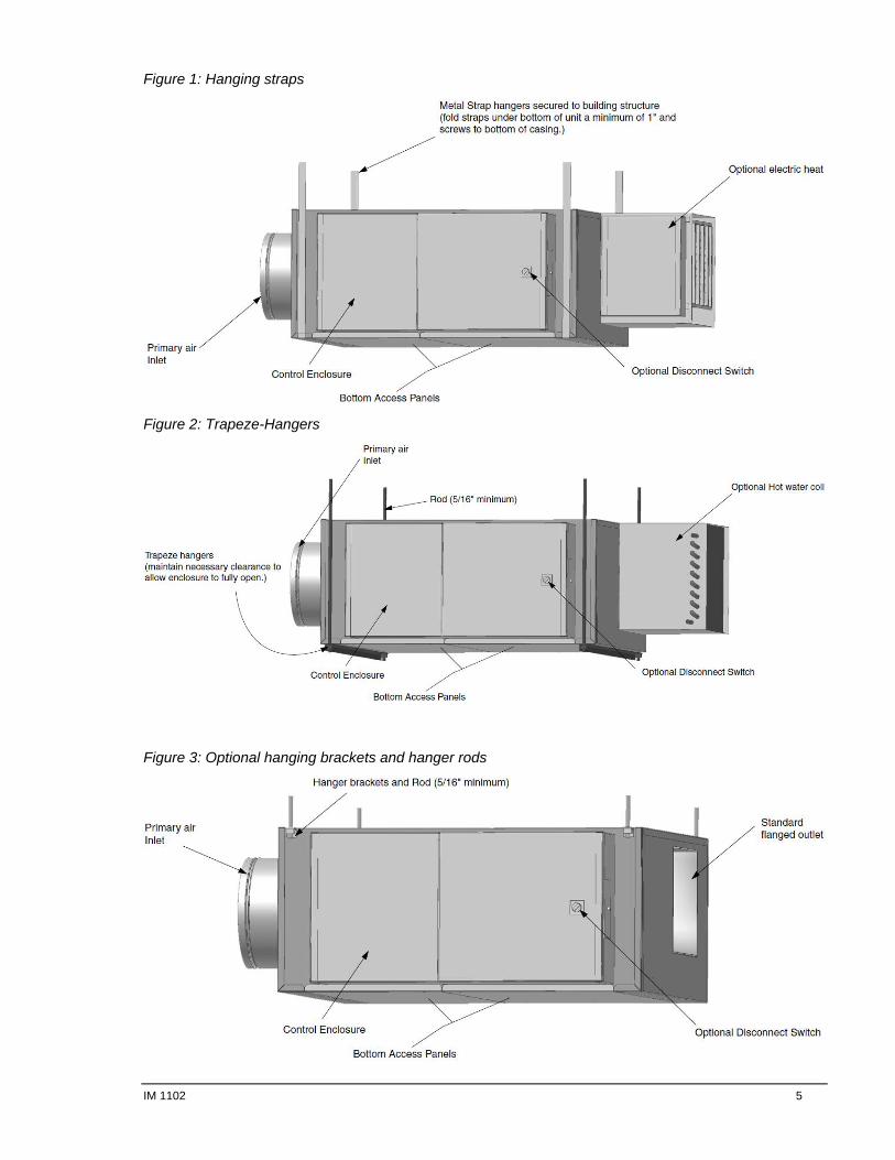
Figure 1: Hanging straps
Figure 2: Trapeze-Hangers
Figure 3: Optional hanging brackets and hanger rods
IM 1102 5
! CAUTION
The equipment is heavy and mounted in the ceiling. Use caution and follow OSHA or SMACNA installation guidelines.
Connecting Ductwork Slip each inlet duct over the inlet collar of the terminal. Fasten and seal the connection by the method prescribed by the job specification. The diameter of the inlet duct "D" in inches must be equal to the listed inlet size of the terminal; e.g. a duct that actually measures 8 inches must be fitted to a terminal with a size 8 inlet. The inlet collar of the terminal is made 1/8 inch smaller than listed size in order to fit inside the duct. Note: Do not insert ductwork inside the inlet collar of the assembly. Inlet duct should be installed in accordance with SMACNA guidelines. If a single point electronic velocity sensor is installed, it is recommended that the installer provide three to five diameters of straight duct at the terminal inlet. The outlet end of the fan powered terminal is designed for use with flanged ductwork (slip and drive duct connections optional). A rectangular duct the size listed in the catalog for the fan powered case size should be attached. Ductwork should be fastened and sealed per the job specifications.
Minimum clearance For Access Fan Powered Air Terminals require sufficient clearance to allow servicing of the motor, blower, actuator, controls and single point electric power hook-up. A minimum of 3 inches of vertical clearance is required below the bottom of the unit and sufficient horizontal clearance to the side to allow the bottom access panels to clear the bottom of the fan powered air terminal unit. Horizontal clearance requirements are dependent upon access panel dimensions which are indicated on the appropriate submittals. For control panel enclosure access a minimum of 18" is recommended. Do not block access to control panel enclosure. See the appropriate submittal for control panel location. NOTE: These clearance recommendations are not meant to preclude NEC requirements or local building codes that may be applicable, which are the responsibility of the installing contractor.
Field Electrical Wiring
! WARNING
Electric shock hazard. Can cause personal injury or equipment damage.
This equipment must be properly grounded. Connections and service to the MicroTech® III Chiller Unit Controller must be performed only by personnel knowledgeable in the operation of the equipment being controlled.
All field wiring must comply with the local codes and with the National Electrical Code (ANSI/NFPA 70-2002).
When applicable, electrical, control and piping diagrams are shown on labels attached to the exterior of the fan powered terminal, or to the inside cover of the control
Use copper conductors only!
All fan powered air terminal units are factory wired for a single point electrical connection to the fan and the optional electric heater.
6 IM 1102

All electric heaters if provided by McQuay are balanced by kW per stage. The installing electrician should rotate these heater stages by phase in order to help balance the building electric load.
All fan powered air terminal units must be properly grounded per NEC 424-14 and 250.
Always check product label for voltage and current data to determine the proper wire size and current protection.
The control cabinet contains live electrical parts! Contacting these parts with the power applied may cause serious injury or death. The control cover must be closed prior to applying electric power to the unit.
Disconnect switches are optional equipment. Caution: Provide a safety disconnect per NEC 424-19, 20 & 21.
Unless ordered with electric heaters, motor fusing is optional. Caution: If multiple fan powered units are connected to one branch circuit breaker, factory motor fusing is required.
These recommendations are not meant to preclude NEC requirements or local building codes that may be applicable, which are the responsibility of the installing contractor.
! WARNING
Electric shock hazard. Can cause personal injury or equipment damage.
This equipment must be properly grounded. Connections and service to the MicroTech® III Chiller Unit Controller must be performed only by personnel knowledgeable in the operation of the equipment being controlled.
Fan Powered Air Terminal Units with Electric Heat
Always inspect the electric coils for damage prior to installing the single duct unit.
See above wiring instructions.
! WARNING
Electric shock hazard. Can cause personal injury or equipment damage.
This equipment must be properly grounded. Connections and service to the MicroTech III Chiller Unit Controller must be performed only by personnel knowledgeable in the operation of the equipment being controlled.
Fan Powered Air Terminal Units with Hot Water Coils Always inspect the hot water coils for damage prior to installing the single duct unit. CAUTION: The copper tubing should not be used as lift points. The hot water coil casing is field insulated. The hot water coils do not have a drip pan and are not suitable for use as cooling coils.
IM 1102 7
Controls Detailed information regarding connection, start-up and operating procedures for controls provided by McQuay are available from your local McQuay representative. For information on controls by other manufacturers, contact that manufacturer’s local branch or dealer.
! CAUTION Static sensitive components. Can cause equipment damage. Discharge any static electrical charge by touching the bare metal inside the control panel before performing any service work. Never unplug cables, circuit board terminal blocks, or power plugs while power is applied to the panel.
Important: Units with digital controls, if factory programmed, incorporate specific communication addresses. Installing the terminal in a different location than noted on unit label and building plans may result in excessive start-up labor.
Labeling Fan Powered Air Terminals are shipped from the factory with up to seven different information labels (not all labels pertain to all fan powered units depending upon the type of insulation and the final ship to state).
1) Control Label – affixed to the fan powered terminal casing or the inside of the control panel cover. Shows piping/wiring diagram and control sequence number and fusing (if applicable).
2) Calibration Label – affixed to the fan powered terminal casing. Shows air flow calibration data and control settings (if applicable).
3) I.D. Label – affixed to the fan powered terminal casing. Shows tagging information, customer order number, ETL Logo, McQuay Logo, etc.
4) ARI Certification Label on Fan Powered Terminal Unit – identifies applicable industry test standard and certifies unit is in compliance.
5) ARI Certification Label on Hot Water Coils – identifies applicable industry test standard and certifies hot water coil compliance (if hot water coils is ordered as an accessory).
6) Fiberglass Label – identifies insulation type for units shipped to California.
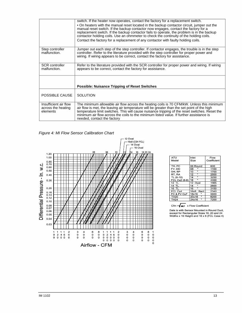
7) Orientation label – identifies the proper air flow direction and the top of the unit. Flow Sensor Fan Powered Air Terminals are shipped with a factory installed pressure differential flow sensor installed. See (Figure 4) for the calibration curve.
8 IM 1102
Initial Start-up / Adjustment of Fan Flow Rate
1. Check that the discharge duct work is connected. The minimum recommended discharge static pressure is 0.2 inches of w.g.
2. Make certain that the electrical connection is properly installed and that all safety covers and access panels are in place.
3. Inspect the fan box and duct work for the presence of any packing / foreign materials and remove if found.
4. Motor is shipped from the factory set at full speed. Allow the motor to warm up for a period greater than 10 minutes prior to adjusting speed control. During this warm up period, inspect the ductwork for leaks and make any necessary repairs. CAUTION: Do not operate the fan box if the downstream ductwork is not present.
5. Flow adjustment: Turn the speed control counterclockwise to reduce the fan speed. Clockwise rotation will increase the fan speed.
6. Set the unit to full heating (maximum induction). Adjust the downstream balancing dampers (if present). Adjust the speed control to deliver the desired air flow rate by measuring the air delivered to the room outlets using a flow hood or other instruments.
7. Set the unit to full cooling (maximum primary air). (Refer to controls literature for detailed control installation information.) The fan may need to be readjusted with the primary air and ventilation air at maximum set point to insure that no supply air is discharged at the plenum air intake port, then recheck full heating.
! WARNING Solid state speed controls cause all electric motors to run hotter and speed reduction should never be below 700 RPM for proper lubrication of motor bearings.
Fan Maintenance Procedure The motor is equipped with permanently lubricated bearings. Inspect the motor, fan and terminal unit for the buildup of dust or other foreign material. Clean as required by the operating environment and type of insulation installed.
IM 1102 9
Troubleshooting
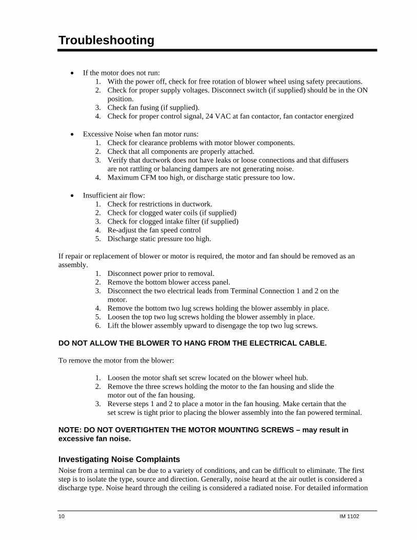
If the motor does not run:
1. With the power off, check for free rotation of blower wheel using safety precautions. 2. Check for proper supply voltages. Disconnect switch (if supplied) should be in the ON
position. 3. Check fan fusing (if supplied). 4. Check for proper control signal, 24 VAC at fan contactor, fan contactor energized
Excessive Noise when fan motor runs:
1. Check for clearance problems with motor blower components. 2. Check that all components are properly attached. 3. Verify that ductwork does not have leaks or loose connections and that diffusers
are not rattling or balancing dampers are not generating noise. 4. Maximum CFM too high, or discharge static pressure too low.
Insufficient air flow:
1. Check for restrictions in ductwork. 2. Check for clogged water coils (if supplied) 3. Check for clogged intake filter (if supplied) 4. Re-adjust the fan speed control 5. Discharge static pressure too high.
If repair or replacement of blower or motor is required, the motor and fan should be removed as an assembly.
1. Disconnect power prior to removal. 2. Remove the bottom blower access panel. 3. Disconnect the two electrical leads from Terminal Connection 1 and 2 on the
motor. 4. Remove the bottom two lug screws holding the blower assembly in place. 5. Loosen the top two lug screws holding the blower assembly in place. 6. Lift the blower assembly upward to disengage the top two lug screws.
DO NOT ALLOW THE BLOWER TO HANG FROM THE ELECTRICAL CABLE. To remove the motor from the blower:
1. Loosen the motor shaft set screw located on the blower wheel hub. 2. Remove the three screws holding the motor to the fan housing and slide the
motor out of the fan housing. 3. Reverse steps 1 and 2 to place a motor in the fan housing. Make certain that the
set screw is tight prior to placing the blower assembly into the fan powered terminal. NOTE: DO NOT OVERTIGHTEN THE MOTOR MOUNTING SCREWS – may result in excessive fan noise.
Investigating Noise Complaints Noise from a terminal can be due to a variety of conditions, and can be difficult to eliminate. The first step is to isolate the type, source and direction. Generally, noise heard at the air outlet is considered a discharge type. Noise heard through the ceiling is considered a radiated noise. For detailed information
10 IM 1102
concerning noise transmission in buildings see ARI Standard 885-98, PROCEDURE FOR ESTIMATING OCCUPIED SPACE SOUND LEVELS IN THE APPLICATION OF AIR TERMINALS AND AIR OUTLETS.
Discharge Noise Discharge noise is usually caused by high static or little to no internal duct lining downstream of the terminal, or it can sometimes be caused by the air outlet itself. Air outlet generated sounds can be reduced by reducing flow or increasing air outlet size. Reducing static pressure, or flow, or adding additional attenuation materials will reduce discharge sounds from the terminal unit. Sometimes, moving the flex duct between the terminal and air outlet so the air must make an additional turn will help with the discharge sound.
Radiated Noise Radiated noise is most commonly associated with fan powered terminal units. Proper suspension, isolation and ducting of these terminals are critical to minimize any vibrations from being transmitted through the suspension or ductwork. Severe vibrations, or any sounds of knocking or rubbing should be immediately investigated and the terminal shut off. Occasionally, shipping/handling/installing can unbalance a blower.
Controls Contact your McQuay representative for information concerning controls provided by McQuay. For controls provided by others, contact the local control representative for assistance.
! WARNING
Electric shock hazard. Can cause personal injury or equipment damage.
This equipment must be properly grounded. Connections and service to the MicroTech III Chiller Unit Controller must be performed only by personnel knowledgeable in the operation of the equipment being controlled.
! CAUTION
Static sensitive components. Can cause equipment damage. Discharge any static electrical charge by touching the bare metal inside the control panel before performing any service work. Never unplug cables, circuit board terminal blocks, or power plugs while power is applied to the panel.
Electric Duct Heater If the heater does not operate:
Check electric power into the unit, and verify that the wiring agrees with the label diagram located on the terminal unit casing.
Verify that the unit is installed properly (i.e., according to the air flow orientation label). Review the wiring diagram supplied with the heater to verify the field wiring is correct and of the proper gauge and that the heater is properly grounded.
If the heater cycles on and off:
Verify that the airflow is uniformly distributed across the face of the heater. Check for obstructions in the duct, or insufficient air flow (CFM) (see label for minimum CFM).
IM 1102 11
If conditioned space fails to warm-up: Make certain that the heater controls and the thermostat are compatible and wired properly.
Relocate the thermostat if it is located in a position that is too warm. If conditioned space overheats:
Make certain that the heater controls and the thermostat are compatible and wired properly. Relocate the thermostat if it is located in a position that is too cool. Verify that the air distribution to the space is appropriate for the required thermal load.
! WARNING
Electric shock hazard. Can cause personal injury or equipment damage.
This equipment must be properly grounded. Connections and service to the MicroTech III Chiller Unit Controller must be performed only by personnel knowledgeable in the operation of the equipment being controlled.
Specific Electric Heat Troubleshooting Procedures:
Warning: On all troubleshooting that requires you to work inside the heater wiring casing, disconnect power first! Jumpers are used for diagnostic purposes only – remove all jumpers prior to returning unit to operation.
Possible Cause Solution Power not properly connected to the heater.
With a voltmeter, check the power wiring terminals to insure the proper voltage is available to the element side of the power terminal block or to the field side of the disconnect switch, power fusing, or circuit breakers. If proper voltage is not present, check the terminal studs for proper wiring and check the power source for power.
Disconnect switch, toggle switch, or circuit breaker set to OFF
Set switch circuit breakers to the ON position.
Power fuses are blown or circuit breakers have tripped.
Replace fuses with the same type and amperage as those provided with the heater, or reset circuit breaker by first setting the breaker to the OFF position, and then resetting it to the ON position. With an ammeter, check amperage draw on the power lines. For heaters with fusing, amperage draw should not exceed the fuse. For heaters with circuit breakers, amperage should not exceed the rated value. If the amperage draw is excessive, check the power supply as described above for proper voltage. If the fuse/circuit breaker trips upon application of power, check for a short. If no short is present and the power supply wiring/voltage is correct, contact the factory for further assistance.
Manual reset switch has been tripped.
Push manual reset button. Manual reset is usually located in the control cabinet near the bottom of the been tripped. element header.
Air static switch is not engaging.
Jumper out the air static switch by connecting the lead attached to the normally open stud, to the normally closed stud. If heater operates, the problem may be the air static switch. Disconnect the pneumatic tubing from the pitot tube located in the control cabinet. Attach a magnehelic gauge to the pitot tube. Available static pressure at the pitot tube should be <= -0.03" S.P. or >= +0.03" S.P. If the available static pressure is in the dead band between these two ranges, the switch will not engage and some method must be devised to increase the available static pressure. If sufficient static pressure is available, check to insure the pneumatic tube is connected to the correct port of the switch. For negative pressure, connect to the low port. For positive pressure, connect to the high port. If the air static switch still fails to operate, contact the factory for a replacement switch.
Automatic reset switch bad.
Allow the duct temperature to cool below 90°F. If the heater does not operate, jumper out the automatic reset switch. If the heater now operates, contact the factory for a replacement switch. Manual reset switch Allow the duct temperature to cool below 90°F. If the heater does not operate, do the following: • On heaters with the manual reset installed in the power wiring, jumper out the manual reset
12 IM 1102
switch. If the heater now operates, contact the factory for a replacement switch. • On heaters with the manual reset located in the backup contactor circuit, jumper out the manual reset switch. If the backup contactor now engages, contact the factory for a replacement switch. If the backup contactor fails to operate, the problem is in the backup contactor holding coils. Use an ohmmeter to check the continuity of the holding coils. Contact the factory for a replacement of any contactor with faulty holding coils.
Step controller malfunction.
Jumper out each step of the step controller. If contactor engages, the trouble is in the step controller. Refer to the literature provided with the step controller for proper power and wiring. If wiring appears to be correct, contact the factory for assistance.
SCR controller malfunction.
Refer to the literature provided with the SCR controller for proper power and wiring. If wiring appears to be correct, contact the factory for assistance.
Possible: Nuisance Tripping of Reset Switches
POSSIBLE CAUSE
SOLUTION
Insufficient air flow across the heating elements
The minimum allowable air flow across the heating coils is 70 CFM/kW. Unless this minimum air flow is met, the leaving air temperature will be greater than the set point of the high temperature limit switches. This will cause nuisance tripping of the reset switches. Reset the minimum air flow across the coils to the minimum listed value. If further assistance is needed, contact the factory
Figure 4: MI Flow Sensor Calibration Chart
IM 1102 13
This document contains the most current product information as of this printing. For the most current product information, please go to www.mcquay.com. All McQuay equipment is sold pursuant to McQuay’s Standard Terms and Conditions of Sale and Limited Warranty.
www.mcquay.com
800-432-1432
14 IM 1102