parametric design of grapes elevators in solidworks using
TRANSCRIPT

Parametric design of grapes elevators
in Solidworks using Application
Programming Interface
Sideris Vougioukakis
SCHOOL OF ECONOMICS, BUSINESS ADMINISTRATION & LEGAL STUDIES / SCIENCE AND TECHNOLOGY
A thesis submitted for the degree of Master of Science (MSc) in Strategic Product Design
January 2020 Thessaloniki – Greece
Student Name: Sideris Name Surname:Vougioukakis
SID: 1106180027

Supervisor: Prof. Panagiotis Kyratsis
I hereby declare that the work submitted is mine and that where I have made use of another’s work, I have attributed the source(s) according to the Regulations set in the Student’s Handbook.
January 2020 Thessaloniki - Greece
Abstract
This dissertation was written as part of the MSc in Strategic Product Design at the International Hellenic University. The core use of SolidWorks in industry is to create CAD parts (SolidWorks Part mode), assemble the parts to create products (SolidWorks Assembly mode), and create drawings of the parts and assemblies for production and manufacturing (SolidWorks Drawing mode). The main purpose of this study is to design a machine in Solidworks Software(Elevator for grapes)and next to automate as possible all the processes from assembly and production drawings to parts lists and codification of components using macros and Solidworks Application Programming Interface (API). The dissertation can be separated in two main fields. First in the model design with usual Solidworks tools and methods and secondly design automation with the API programming methods and VBA tools.
ACKNOWLEDGMENTS
I would like to express thanks to my wife Olga , my daughter Maria and my son Giannis without whom I would be incomplete. Although sometimes we had disagreements, your presence provided me with the motivation I so desperately needed through the entire thesis process. I also give thanks to my Supervisor Dr.Panagiotis Kyratsis.Thank you for your patience and assistance, dedication and support. I would also like to acknowledge Dr.Dimitrios Tzetzis for his efforts and support to take up the subject of the Dissertation and Keith Rice for the power access in his valuable video API tutorials. Finally, I would like to thank all International Hellenic University Academic and student community for the completion of one year of expedient experience in this postgraduate programme.
Sideris Vougioukakis 24/01/2020
-i-
Preface
LIST OF FIGURES
Picture 1.Zampelli Enotech Elevator……………………………………………………PAGE 2 Picture 2 BUCHER VASLIN DELTA Elevator…………………………………………..PAGE 3 Picture 3 Main elevator components......................................................PAGE 8 Picture 4 Inlet Tank……………………………………………………………………………..PAGE 9 Picture 5 Parts of Inlet tank with hopper……………………………………………..PAGE 9 Picture 6.Pulley design Considerations………………………………………………..PAGE 10 Picture 7.Base weldment part……………………………………………………………..PAGE 11 Picture 8.Base structure assembly……………………………………………………….PAGE 11 Picture 9.Lifting mechanism main parts………………………………………………PAGE 12 Picture 10.Belt support stable part………………………………………………………PAGE 13 Picture 11.Belt Support changed part………………………………………………….PAGE 14 Picture 12.Conveyor Belt……………………………………………………………………..PAGE 15 Picture 13. Outlet with motor………………………………………………………………PAGE 16 Picture 14. Initial Userform VBA automation Macro..............................PAGE 17 Picture 15.Userform with correct selections...........................................PAGE 18 Picture 16.Userform with wrong selections.............................................PAGE 18 Picture 17.Base Flange Feature Interface Solidworks API……………………..PAGE 19 Picture 18.Modification of part 021………………………………………………………PAGE 21 Picture 19.Modification of part 023………………………………………………………PAGE 21 Picture 20 Modification of base weldment part ……………………………………PAGE 22 Picture 21 Angle mate automatic creation...............................................PAGE 25 Picture 22.First click (run) completed)......................................................PAGE 26 Picture 23 Automatic Belt Creation result.................................................PAGE 31 Picture 24 locate the belt in the Assembly and create the final model....PAGE 32 Picture 25.Final Assembly Drawing............................................................PAGE 42 Picture 26.Weldment base part drawing...................................................PAGE 44 Picture 27.Upper changed belt support drawing.......................................PAGE 46 Picture 28.Down changed part belt support drawing................................PAGE 48 Picture 29.Belt drawing..............................................................................PAGE 50

-ii-
-iii-
Contents
ABSTRACT ...........................................................................................................................
ACKNOWLEDGMENTS ........................................................................................................
PREFACE ............................................................................................................................ I
LIST OF FIGURES ............................................................................................................... I
CONTENTS ...................................................................................................................... III
INTRODUCTION ................................................................................................................ 1
DESIGN USING USUAL SOLIDWORKS METHODS ............................................................. 8
MACHINE DESCRIPTION ..................................................................................................... 8
DESIGN OF THE INLET TANK WITH HOPPER ............................................................................. 8
DESIGN OF THE BASE STRUCTURE ....................................................................................... 11
DESIGN OF THE WELDMENT PART ...................................................................................... 11
Design of the lifting mechanism ....................................................................... 12
BELT SUPPORT STABLE PART ............................................................................................. 13
BELT SUPPORT CHANGED PART .......................................................................................... 13
BELT WITH FLIGHTS ........................................................................................................ 14
OUTLET WITH MOTOR ..................................................................................................... 15
MODEL DESIGN AUTOMATION USING SOLIDWORKS API ............................................ 17
USERFORM PRESENTATION .............................................................................................. 17
BASEFLANGEFEATURE INTERFACE ...................................................................................... 19
MODIFICATION OF THE BASE PART ..................................................................................... 22
MODIFICATION OF INCLINATION ........................................................................................ 23
Automatic creation of the model folder ........................................................... 25
Belt Creation .................................................................................................... 26
PACK AND GO AND BILL OF MATERIALS ................................................. 32
DRAWING AUTOMATION .............................................................................................. 39
CONCLUSIONS ................................................................................................................ 51
BIBLIOGRAPHY ............................................................................................................... 53

-iv-
APPENDIX ......................................................................................................................... 1
-1-
Introduction
Design automation offers two benefits. First, it enhances productivity. Second, it helps with repetitive tasks that are mundane. For example, if we follow the same design process over and over, automating it would be the logical thing to do. A higher level of automation than using macros is to use Visual Basic (VB) or another programming language to perform full automation and have better control of the automation. As a matter of fact, VB is the programming engine behind macros. Instead of writing the macro VB code, the SolidWorks macro interface enables us to generate the code automatically while we perform the design tasks as usual. It is this VB code that we save in a file when we save the macro. We can use the VB editor to edit and tweak the VB code. The SOLIDWORKS Application Programming Interface (API) is a COM programming interface to the SOLIDWORKS software. Functions in the API provide programmers with direct access to SOLIDWORKS functionality. The API contains hundreds of functions that somebody can call from Visual Basic (VB), Visual Basic for Applications (VBA), VB.NET, C++, C#, or SOLIDWORKS macro files. Although multiple programming languages offer a lot of possibilities in this study we will focus in Solidworks API capabilities using the initially installed VBA editor. Initially a literature research in the field and the information of multiple sources is vast important and also the repetitive effort and practice in VBA code programming.
Key References
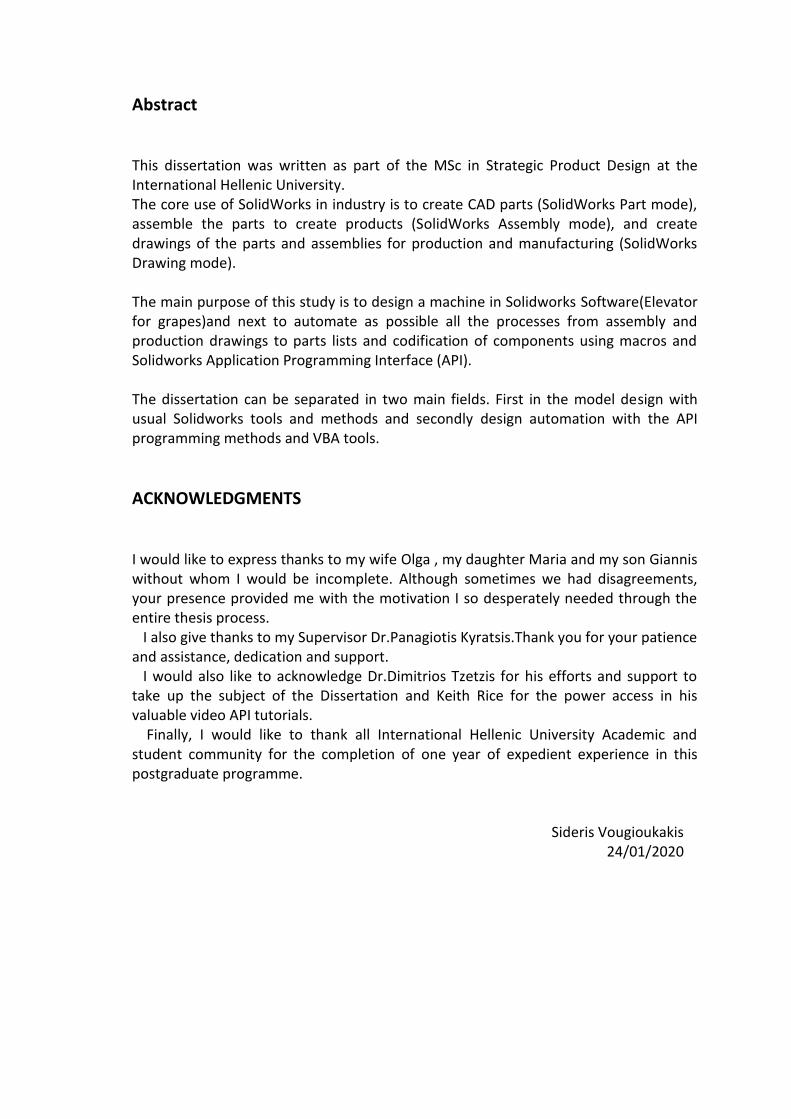
The machine element to be designed is a belt elevator for grapes. Although in Greece and especially in Northern Greece there are a lot of high class wineries, the relative manufacturing firms to support this development are inadequate. For this reason machines like a belt elevator are imported from other European countries like Italy or France. In the following pictures two such machines are presented with their characteristics one Italian and one French. 1.Zampelli Enotech conveyor belt elevator With a strong tradition of over 100 years ZAMBELLI ENOTECH (founded in 1888) is a reliable reference point in the Italian market and abroad, for machinery and equipment of the highest quality in the industry wine, fruit and oil.

-2-
Picture 1.Zampelli Enotech Elevator source: http://www.zambellienotech.it
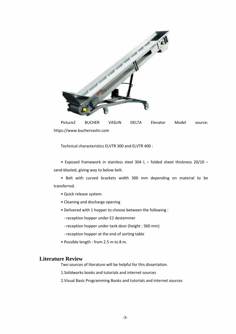
Characteristics: Mechanical Variable Speed Hydraulic Lift Hopper Width: 39" (S Series) or 47" (M Series) Conveyor Width: 12" (S Series) or 20" (M Series) Belt is food-grade PVC Hopper, Chute, and Frame constructed entirely of AISI 304 Stainless Steel 220v, 3 Phase Motor Italian Made by Zambelli 2.BUCHER VASLIN grapes Elevators Mobile belt elevators Delta ELVTR & TRE The mobile belt elevator enables to feed presses, destemmers, sorting tables, maceration tanks… with fresh grapes, to feed presses with macerated grapes and to evacuate stems and dried pomace. Bucher Vaslin designs, manufactures, and sells, only or through its network of exclusive distributors, processes and materials exclusively intended for the transformation of grapes to wine ready for marketing. From the first Joseph Vaslin presses in 1856 and Johann Bucher presses in 1874, to today’s extensive range, they have been providing an unique service to wine-makers and oenologist.
-3-
Picture2 BUCHER VASLIN DELTA Elevator Model source:
https://www.buchervaslin.com
Technical characteristics ELVTR 300 and ELVTR 400 :
• Exposed framework in stainless steel 304 L – folded sheet thickness 20/10 –
sand-blasted, giving way to below belt.
• Belt with curved brackets width 300 mm depending on material to be
transferred.
• Quick release system.
• Cleaning and discharge opening
• Delivered with 1 hopper to choose between the following :
- reception hopper under E2 destemmer
- reception hopper under tank door (height : 360 mm)
- reception hopper at the end of sorting table
• Possible length : from 2.5 m to 8 m.
Literature Review Two sources of literature will be helpful for this dissertation.
1.Solidworks books and tutorials and internet sources
2.Visual Basic Programming Books and tutorials and internet sources
-4-
Some useful book sources for Solidworks effective Cad Design are:
1.Parametric modeling with Solidworks 2015, [Paul_Schilling,_Randy_Shih],SDC
Publications 2015
2.Mastering Solidworks, Matt Lombart, Copyright © 2019 by John Wiley & Sons,
Inc., Indianapolis, Indiana
Some valuable book sources for Solidworks API and VBA programming are:
Automating SolidWorks 2011 Using Macros, Mike Spens, Schroff Development
Corporation,2010
Mike Spens other book versions are Automating SolidWorks 2014,2015,2017,2019
Solidworks 2008 API Programming and Automation ,Luke Malpass
,Angelsix.com,2008 ,Second Edition
Solidworks 2009 API,Advanced Product development, Luke Malpass,
Angelsix.com,2008 ,Second Edition
Visual Basic and Visual Basic Net for Scientists and Engineers, Christopher M.Frenz.
A valuable source for learning VBA and VB.net with examples and implementations
in engineering applications.
Internet offers a wide range of tutorials in the subject and a research concludes to
the following as the most valuable:
1)https://www.cadsharp.com Solidworks API and PDM API Training and Services
2) http://www.angelsix.com/solidworks Automation software , macros and add ins
for Solidworks.
3).https://help.solidworks.com/2019/English/api/sldworksapiprogguide
Solidworks API Help
4).https://my.solidworks.com/training/elearning/68/api-fundamentals
An interesting book in engineering documentation and work management is:
Engineering DOCUMENTATION CONTROL HANDBOOK CONFIGURATION
MANAGEMENT AND PRODUCT LIFECYCLE MANAGEMENT,Frank B.Watts
,Elsevier,Fourth Edition 2012.
Some useful articles on the subject are:
Towards modeling of assemblies for product design, Rajneet Sodhi and Joshua U
Turner,1994 Butter worth Heinemann Ltd
Functional understanding of Assembly Modelling Jin-Kang Gui and Martti Mäntylä,
1994 Butter worth Heinemann Ltd
-5-
Automated Tool Selection for Computer-Aided Process Planning in Sheet Metal
Bending, J. R. Duflou’ (2), T. H. M. Nguyen’, J.-P. Kruth’ ( I ) , D. Cattrysse2, Department
of Mechanical Engineering, Centre for Industrial Management, Katholieke Universiteit
Leuven, Celestijnenlaan 300, 3001 Leuven, Belgium.
Intelligent dimensioning of Mechanical parts based on feature extraction,Ke-Zhang
Chen,Xin An Feng,Quan-Sheng Lu,Department of Mechanical Engineering ,The
University of Hong-Kong,31 August 2000.
Intelligent aproaches for generating assembly drawings from 3-D computer models
of mechanical parts, Ke-Zhang Chen,Xin An Feng,Lan Ding,Department of Mechanical
Engineering ,The University of Hong-Kong,31 February 2001.
4. Research Design & Methodology
1. Research of all available topics and literature resources on the subject.
Research and study off most of the accessible sources on the subject indicates that
Solidworks API is an Application with a lot of features to examine and to be familiar
with it needs a lot of practice and preservance. Although studying the available
literature you get a general idea it takes time to write your own code and you must
understand the cause and result of each letter ,word and line you write.
2.Study and practice with Solidworks AP interface and macros design.
Keith Rice of Cadsharp ( a master in the field) wrote (2012) an article about the
common mistakes that API programmers doing. I think it is the most interesting
approach of all that I have read so far and it can be used as a guide for the study
procedure in order to have a useful result. Some of the advices from this text are:
VB.NET, C#, and C++ are languages with a lot of possibilities. However, if the applied
macros are relatively not so complex,these possibilities are completely unuseful. A
novice API programmer, probably cares only about to automate his work. If someone
tries to implement Solidworks API methods using other Languages than VBA ,then
spends a lot of time in learning the programming language and less time in
understanding the Solidworks API issues.If someone is familiar with Solidworks API
interface then is ready to try a more more powerful language like VB NET,or C#.
-6-
For a new API user , it is more preferable to use the macro recorder. Although the
recorder is a tool that it seems able to give access to all the API specific solutions,it can
not record for example custom properties like changing an angle in an angle mate.
Secondly, the macro recorder usually prompts the user to perform tasks using the API
with the same manner that someone would perform with traditional Solidworks
methods, for example the procedure required to create a section view or change a
face’s color, is totally different when using the Solidworks API than the required steps
with usual Solidworks tools for the same tasks. Finally, the produced code from the
recorder is sometimes messy and contains code information and code lines that is
completely unnecessary. A more successful approach is to use the macro recorder to
locate the API argument or interface and then to use the API Help to discover all the
possibilities of the specific API tool. Additionally the API help contains information
about the up-to-date methods and the obsolete methods and also useful examples for
each method.
The API Help is not just a valuable source for advanced developers. If someone is not
able to navigate through the API Help in order to find the desired method to apply his
macro production will be poor and will be in the same level with macro recorder or the
copy and paste from the code that someone else created. With the index tab of API
Help someone can find easily the desired API tool or interface and every tool or call
have its own specific page and in most of the cases an example that describes
accurately the tool implementation.
The deep understanding of the Soliworks API Object Model is the key knowledge that
someone can have to be in an advanced level as an API programmer.Every interaction
within Solidworks is taken as an object by the Solidworks API,for example an edge, a
drawing view ,a part or an assembly and so on. It is important to know that these
objects are hierarchically arranged. Thus,if you need to change the color of a face you
must first have access to the face’s body, to have access to the body you must first
have access to the part document and before this someone must have access to the
Solidworks Application.
Modular programming code helps someone to easily use again or debug the code.
For example if a macro requires to use a specific value of a custom property in a code

-7-
called “Partmaterial”.Instead of writing the same lines of code many times you can
create a module called for example “Getpartmaterial” that is called by the main
module code.
In order someone to become a Solidworks Api programmer requires persistence. As a
programmer, you are called to overcome barriers often. Every barrier, is the
opportunity for another success. Learn to adore these small victories. Practicing will
make you day by day better. Once you understand the API Help and Object Model,
you’ll truly be amazed at how quickly you can write macros.You will very often enjoy
your work results.

-8-
Design using usual Solidworks Methods
In this chapter the design of the elevator machine will be implemented and described using Solidworks traditional tools
Machine Description
The designed machine will be used to convey grapes in an upper level with a capacity of 12-15 tons per hour.The Belt moving mechanism is consisted of two rollers and a driving motor in the upper part. The main parts of the machine is shown in the following picture.
Picture 3.Main elevator components(Designed with Solidworks 2018 Educational version) For presentation reasons is created a special drawing sheet template which will be used for automation in next chapters.
Design of the inlet tank with hopper
The inlet tank which is the entrance of the product to the machine and placed in the down part of the belt elevator with the innovative design of the mechanism of the pulley for easy cleaning and maintenance is shown in the following figure:

-9-
Picture 4.Inlet tank (Designed with Solidworks 2018 Educational version)
Picture 5.Parts of inlet tank with hopper.(Designed with Solidworks Educational version 2018)

-10-
The tank is liquid proof and in the lower point there is a tapped exit for draining and cleaning purposes. The innovation in this design approach is that the pulley does not mounted in bearings but in a bracket. The hopper design depends in the needs of the client and the current design is only indicative. All parts are from stainless steel AISI 304 or from polyethylene FDA approved, for example the part N.009 is the pulley and is made from polyethylene. Design considerations for the pulley which is a critical element for the machine function are shown in the following picture:
Picture 6.Pulley design Considerations .Source: Habasit AG Conveyor Belts Engineering guide. For the tracking of conveyor belts cylindrical-conically formed (trapezoidal crowned) or simple crowned pulleys are effective for use. As the belt tries to run to the highest point of a pulley diameter, it is constantly directed towards the center of the pulley by the conical ends. If the belt has the tendency to run to one side, e.g. to the left, the belt centering forces on the left increase as the contact area increases and, conversely, the tracking forces on right end of pulley decrease. The resultant force consequently directs the belt back toward its centered (neutral) location on the pulley where the centering forces become balanced on each side.(5)
-11-
Design of the base structure
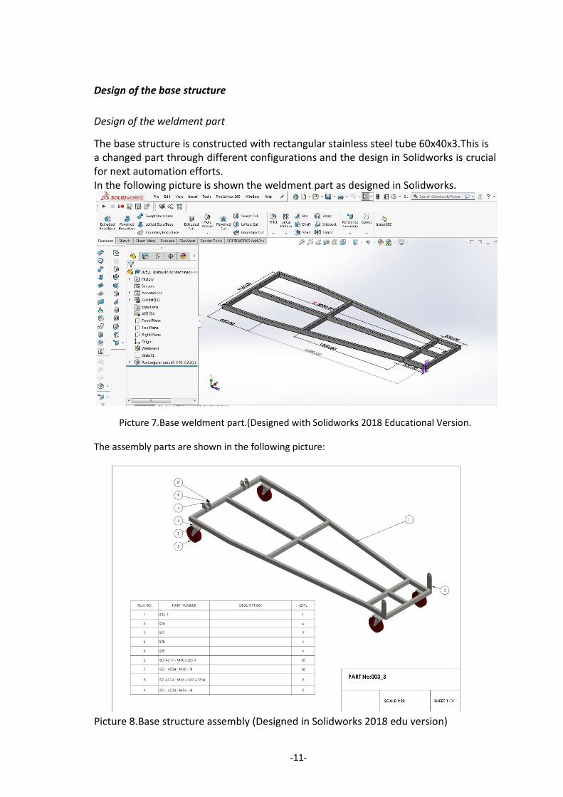
Design of the weldment part
The base structure is constructed with rectangular stainless steel tube 60x40x3.This is a changed part through different configurations and the design in Solidworks is crucial for next automation efforts. In the following picture is shown the weldment part as designed in Solidworks.
Picture 7.Base weldment part.(Designed with Solidworks 2018 Educational Version.
The assembly parts are shown in the following picture:
Picture 8.Base structure assembly (Designed in Solidworks 2018 edu version)

-12-
The base is mounted in four caster Φ200 stainless steel base wheels.
Design of the lifting mechanism
For the lifting mechanism is used a mechanical trapezoidal screw M32.The structure is based in rectangular tubes 60x60x3 and 50x50x2 all in stainless steel as shown in the following picture:
Picture 9.Lifting mechanism main parts (Designed with Solidworks 2018 educational version)

-13-
Belt Support stable part
The belt support part that is stable has 2500 mm length and is constructed from 2 mm sheet metal stainless steel. The upper part has the section form as shown in the following picture for better belt durability and functional reasons.
Picture 10.Belt support stable part.(Designed with Solidworks 2019 Educational version.)
Belt support changed part
This part has the same structure with the stable part the different is that this part will take different lengths in order to have multiple machine configurations. The support of rectangular tube 60x40 is placed in the middle of parts length and it has the connectors with the lifting mechanism.

-14-
Picture 11.Belt Support changed part(Design with Solidworks 2018 Educational Version.
Belt With Flights
The conveyor belt is from pvc and it has width of 600 mm,it has flights of 60 mm height in a distance of 300 mm between them. The flights hold the product from rolling back in the inclined conveyor.

-15-
Picture 12.Conveyor Belt (Designed with Solidworks 2018 Educational Version) In later chapter we will examine how this belt will be created automatically with VBA.
Outlet with motor
The upper part of the machine is the outlet and it has the driving motor with chain mechanism. The chain is designed in a realistic approach using the fill path tool of Solidworks program. The driving pulley is made from stainless steel with rubber coat knurled in order to have better fit with the belt.The motor selection procedure is a matter of the torque applied in pulleys and it depends from the product weight and other factors and it comes from a sequence of calculations which will not be analytically presented in the study. The motor Model is courtesy of Motovario Group from Italy as it is offered their worldwide customers.Motovario Group has 3D models for the most of its products.

-16-
Picture 13 Outlet with motor (Designed with Solidworks 2018 Educational Version)

-17-
MODEL DESIGN AUTOMATION USING SOLIDWORKS API
In this chapter we will use the Solidworks application programming Interface in order to automate the design procedure of the 3D model. In order to create an amount of models we will create a VBA macro that changes the changed parts according to specific selections and also the user should have the ability to select inclination of the model.
Userform Presentation
The Automation macro initiates with a userform in which the user can type the length of changed parts according to the model that he desires to create.The changed distance has a variation from 300 to 2000 mm.If the user types a value that is not between these limits a pop up message prompts the user to select the correct values.The code convert the typed number to the next hundrened number.For exampe if the user types 1287 the changed length A will be 1300.Additionally the changed parts length B of the base weldment part will automatically changed to the half of the distance A.The user also can select inclination from 32o to 37o and the code creates a limit angle mate in the assembly. The model Automation macro,created in VBA,has the capability to create 17 models X 6 different inclinations,in total 105 different models. In the following pictures these steps are shown one by one.
Picture 14.Initial Userform VBA automation Macro. The Next picture shows the case that the user selects a value between limits The user types the value 1030 and a message box prompts the user to continue. If the user clicks ok the macro runs.

-18-
Picture 15.Userform with correct selections
Picture 16.Userform with wrong selections
-19-
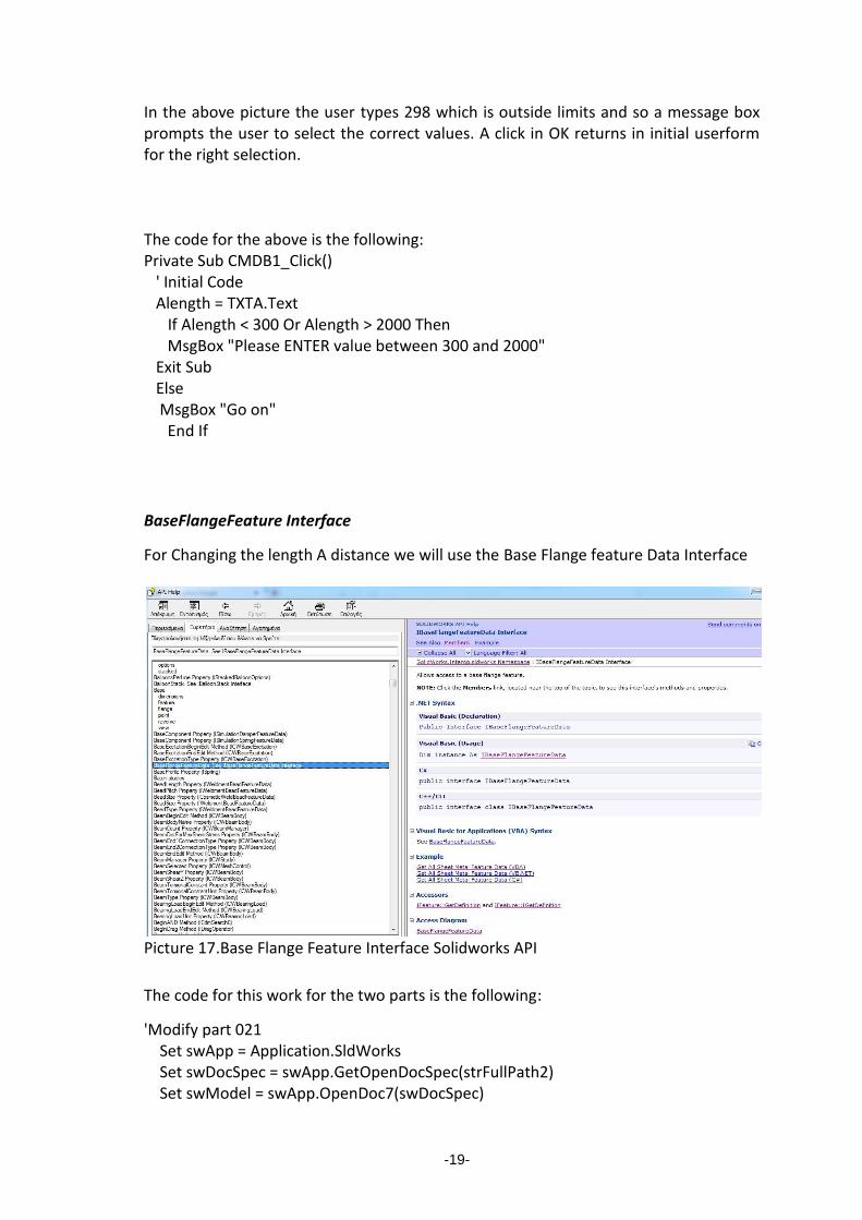
In the above picture the user types 298 which is outside limits and so a message box prompts the user to select the correct values. A click in OK returns in initial userform for the right selection. Τhe code for the above is the following: Private Sub CMDB1_Click() ' Initial Code Alength = TXTA.Text If Alength < 300 Or Alength > 2000 Then MsgBox "Please ENTER value between 300 and 2000" Exit Sub Else MsgBox "Go on" End If
BaseFlangeFeature Interface
For Changing the length A distance we will use the Base Flange feature Data Interface
Picture 17.Base Flange Feature Interface Solidworks API
The code for this work for the two parts is the following:
'Modify part 021 Set swApp = Application.SldWorks Set swDocSpec = swApp.GetOpenDocSpec(strFullPath2) Set swModel = swApp.OpenDoc7(swDocSpec)

-20-
'modify base flange Set swselmgr = swModel.SelectionManager boolstatus = swModel.Extension.SelectByID2("Base-Flange1", "BODYFEATURE", 0, 0, 0, False, 0, Nothing, 0) 'change the selection Set swFeat = swselmgr.GetSelectedObject6(1, -1) Set swBaseFlange = swFeat.GetDefinition swBaseFlange.AccessSelections swModel, Nothing swBaseFlange.D1OffsetType = 1 swBaseFlange.D1OffsetDistance = ((Int(TXTA.Text / 100) - (TXTA.Text / 100 - Int(TXTA.Text / 100) > 0)) * 100) / 1000 swFeat.ModifyDefinition swBaseFlange, swModel, Nothing Dim strNewPath As String strNewPath = Replace(swModel.GetPathName, "021", "021_1") swModel.Extension.SaveAs strNewPath, 0, 1 + 2, Nothing, lngErrors, lngWarnings Debug.Print lngErrors Debug.Print lngWarnings swApp.CloseDoc swModel.GetTitle 'Modify part 023 Set swApp = Application.SldWorks Set swDocSpec2 = swApp.GetOpenDocSpec(strFullPath3) Set swModel2 = swApp.OpenDoc7(swDocSpec2) 'modify base flange Set swselmgr = swModel2.SelectionManager boolstatus = swModel2.Extension.SelectByID2("Base-Flange2", "BODYFEATURE", 0, 0, 0, False, 0, Nothing, 0) 'change the selection Set swFeat = swselmgr.GetSelectedObject6(1, -1) Set swBaseFlange = swFeat.GetDefinition swBaseFlange.AccessSelections swModel2, Nothing swBaseFlange.D1OffsetType = 1 swBaseFlange.D1OffsetDistance = ((Int(TXTA.Text / 100) - (TXTA.Text / 100 - Int(TXTA.Text / 100) > 0)) * 100) / 1000 swFeat.ModifyDefinition swBaseFlange, swModel2, Nothing Dim strNewPath2 As String strNewPath2 = Replace(swModel2.GetPathName, "023", "023_1") swModel2.Extension.SaveAs strNewPath2, 0, 1 + 2, Nothing, lngErrors, lngWarnings Debug.Print lngErrors Debug.Print lngWarnings swApp.CloseDoc swModel2.GetTitle
The result of the above is shown in the following pictures The entered value for distance A is 1030 mm

-21-
Picture 18.Modification of part 021
Picture 19.Modification of Part 023
-22-
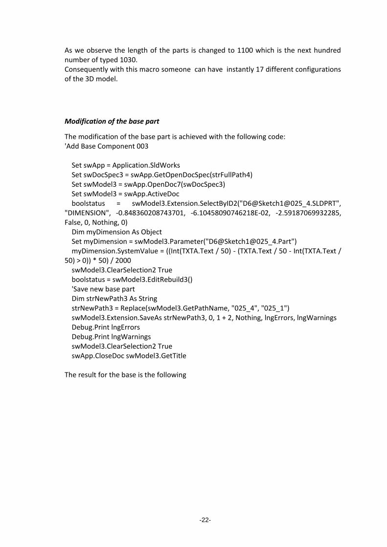
As we observe the length of the parts is changed to 1100 which is the next hundred number of typed 1030. Consequently with this macro someone can have instantly 17 different configurations of the 3D model.
Modification of the base part
The modification of the base part is achieved with the following code: 'Add Base Component 003 Set swApp = Application.SldWorks Set swDocSpec3 = swApp.GetOpenDocSpec(strFullPath4) Set swModel3 = swApp.OpenDoc7(swDocSpec3) Set swModel3 = swApp.ActiveDoc boolstatus = swModel3.Extension.SelectByID2("D6@Sketch1@025_4.SLDPRT", "DIMENSION", -0.848360208743701, -6.10458090746218E-02, -2.59187069932285, False, 0, Nothing, 0) Dim myDimension As Object Set myDimension = swModel3.Parameter("D6@Sketch1@025_4.Part") myDimension.SystemValue = ((Int(TXTA.Text / 50) - (TXTA.Text / 50 - Int(TXTA.Text / 50) > 0)) * 50) / 2000 swModel3.ClearSelection2 True boolstatus = swModel3.EditRebuild3() 'Save new base part Dim strNewPath3 As String strNewPath3 = Replace(swModel3.GetPathName, "025_4", "025_1") swModel3.Extension.SaveAs strNewPath3, 0, 1 + 2, Nothing, lngErrors, lngWarnings Debug.Print lngErrors Debug.Print lngWarnings swModel3.ClearSelection2 True swApp.CloseDoc swModel3.GetTitle The result for the base is the following

-23-
Picture 20 Modification of base weldment part As we onserve the value of distance B is changed to 525 which is the half of 1050 according to the following function: myDimension.SystemValue = ((Int(TXTA.Text / 50) - (TXTA.Text / 50 - Int(TXTA.Text / 50) > 0)) * 50) / 2000
Modification of Inclination
The following code creates a limit angle mate to 3D model assembly: 'Open assembly 007_4 Set swApp = Application.SldWorks Set swDocSpec = swApp.GetOpenDocSpec(strFullPath) Set swModel = swApp.OpenDoc7(swDocSpec) swModel.ForceRebuild3 True boolstatus = swModel.Extension.SelectByID2("003_3-1@007_4", "COMPONENT", 0, 0, 0, False, 0, Nothing, 0) swModel.EditAssembly swModel.ClearSelection2 True boolstatus = swModel.Extension.SelectByID2("003_3-1@007_4/025_1-1@003_3", "COMPONENT", 0, 0, 0, False, 0, Nothing, 0) swModel.EditPart swModel.ClearSelection2 True boolstatus = swModel.Extension.SelectByID2("Sketch1@003_3-1@007_4/025_1-1@003_3", "SKETCH", 0, 0, 0, False, 0, Nothing, 0) swModel.EditSketch swModel.ClearSelection2 True boolstatus = swModel.Extension.SelectByID2("Sketch1@003_3-1@007_4/025_1-1@003_3", "SKETCH", 0, 0, 0, False, 0, Nothing, 0) swModel.ClearSelection2 True

-24-
swModel.SketchManager.InsertSketch True swModel.ClearSelection2 True swModel.AssemblyPartToggle swModel.EditAssembly 'Modify inclination Set swApp = Application.SldWorks Set model = swApp.ActiveDoc boolstatus = swModel.Extension.SelectByID2("Top Plane@020-1@007_4", "PLANE", 0, 0, 0, True, 1, Nothing, 0) boolstatus = swModel.Extension.SelectByID2("PLANEAM1@003_3-1@007_4", "PLANE", 0, 0, 0, True, 1, Nothing, 0) ' Redraw swModel.GraphicsRedraw2 ' Mate Dim swMate As Mate2 ' Create AngleMateFeatureData Dim MateData As AngleMateFeatureData Set MateData = swModel.CreateMateData(6) ' Set the Entities To Mate Dim EntitiesToMate(1) As Object Set EntitiesToMate(0) = swModel.SelectionManager.GetSelectedObject6(1, -1) Set EntitiesToMate(1) = swModel.SelectionManager.GetSelectedObject6(2, -1) Dim EntitiesToMateVar As Variant EntitiesToMateVar = EntitiesToMate MateData.EntitiesToMate = (EntitiesToMateVar) ' Set the Mate Alignment MateData.MateAlignment = 0 ' Set the Limit Angles If Optb32.Value = True Then MateData.Angle = 0.558505360638187 If Optb33.Value = True Then MateData.Angle = 0.575958653158129 If Optb34.Value = True Then MateData.Angle = 0.593411945678072 If Optb35.Value = True Then MateData.Angle = 0.610865238198015 If Optb36.Value = True Then MateData.Angle = 0.628318530717959 If Optb37.Value = True Then MateData.Angle = 0.645771823237902 'If Optb38.Value = True Then MateData.Angle = 0.663225115757845 MateData.MaximumAngle = 0.663225115757847 MateData.MinimumAngle = 0.558505360638187 ' Set the Flip Dimension MateData.FlipDimension = False

-25-
' Create the mate Dim MateFeature As Feature Set MateFeature = swModel.CreateMate(MateData) swModel.ClearSelection2 True swModel.EditRebuild3 swModel.ForceRebuild3 True strNewPath3 = Replace(swModel.GetPathName, "007_4", "007_6") swModel.Extension.SaveAs strNewPath3, 0, 1 + 2, Nothing, lngErrors, lngWarnings Debug.Print lngErrors Debug.Print lngWarnings swApp.CloseDoc swModel.GetTitle the result is shown in the following picture:
Picture 21 Angle mate automatic creation
Automatic creation of the model folder
The macro code creates a new model name and with this name creates a new directory inside the current model creation directory. The codification for this action is as follows: 1.The first three letters are the initials of the phrase Grapes Elevator (GEL)

-26-
2.The next four digits is the added length in mm of the stable and changed belt support part.For example if the distance A is 1030 then is changed to 1100 as described above and adding the length of the stable which is 2500 the total length will be 3600 3.The last two digits is the angle value that is selected in the initial userform. For example if we choose 32o then the folder name will be GEL360032. The folder name is typed in the right hand upper corner of the model figure in the userform as shown in the following figure.
Picture 22.First click (run) completed)
Belt Creation
The following code opens the assembly ,calculates the distance between axes of pulleys and creates the conveyor belt then locates the belt to the assembly with the suitable mates.Additionally selects the correct material for the belt and creates the flights. Dim swApp As SldWorks.SldWorks Dim swModel As SldWorks.ModelDoc2 Dim boolstatus As Boolean Dim swModelDocExt As SldWorks.ModelDocExtension Dim swMeasure As SldWorks.Measure Dim lngErrors As Long Dim lngWarnings As Long Dim swSketchMgr As SldWorks.SketchManager
-27-
Dim swSketchSeg As SldWorks.SketchSegment Dim swFeatMgr As SldWorks.FeatureManager Const strFullPath As String = "C:\SID\Msc STRATEGIC PRODUCT DESIGN\DISSERTATION\3D CAD\007_6.SLDASM" Const strTemplate As String = "C:\ProgramData\SolidWorks\SOLIDWORKS 2018\templates\Part.prtdot" Sub main() Set swApp = Application.SldWorks Set swModel = swApp.OpenDoc6(strFullPath, swDocASSEMBLY, 1, "", lngErrors, lngWarnings) 'select the two axes Set part = swApp.ActiveDoc Set swModelDocExt = swModel.Extension boolstatus = swModel.Extension.SelectByID2("Axis1@000-1@007_6/009-1@000", "AXIS", 0, 0, 0, False, 0, Nothing, 0) oolstatus = swModel.Extension.SelectByID2("Axis2@012-1@007_6/009-1@012/050-1@009", "AXIS", 0, 0, 0, True, 0, Nothing, 0) boolstatus = swModel.Extension.SelectByID2("Axis2@012-1@007_6/009-1@012/050-1@009", "AXIS", 0, 0, 0, False, 0, Nothing, 0) boolstatus = swModel.Extension.SelectByID2("Axis2@012-1@007_6/009-1@012/050-1@009", "AXIS", 0, 0, 0, False, 0, Nothing, 0) 'Measure distance between axes Set swMeasure = swModelDocExt.CreateMeasure 'Can set this to 0 ' 0 = center to center boolstatus = swMeasure.Calculate(Nothing) If (Not (swMeasure.NormalDistance = -1)) Then Debug.Print "Normal distance: " & swMeasure.NormalDistance End If 'Open new part "conveyor belt" Set swModel = swApp.NewDocument(strTemplate, 0, 0, 0) Set swModel = swApp.ActiveDoc Set swSketchMgr = swModel.SketchManager 'select Front plane and insert sketch swModel.Extension.SelectByID2 "Front Plane", "PLANE", 0, 0, 0, False, 0, Nothing, 0 swSketchMgr.InsertSketch True 'turn on direct addition to database swSketchMgr.AddToDB = True 'create sketch entities Set swSketchSeg = swSketchMgr.CreateCenterLine(0, 0, 0, swMeasure.NormalDistance, 0, 0) Set swSketchSeg = swSketchMgr.CreateArc(0, 0, 0, 0.0005, 0.095, 0, 0.0005, -0.095, 0, 1) Set swSketchSeg = swSketchMgr.CreateLine(0.0005, 0.095, 0, swMeasure.NormalDistance + 0.000377789, 0.0715, 0)
-28-
Set swSketchSeg = swSketchMgr.CreateArc(swMeasure.NormalDistance, 0, 0, swMeasure.NormalDistance + 0.000377789, -0.0715, 0, swMeasure.NormalDistance + 0.000377789, 0.0715, 0, 1) Set swSketchSeg = swSketchMgr.CreateLine(0.0005, -0.095, 0, swMeasure.NormalDistance + 0.000377789, -0.0715, 0) swModel.ClearSelection2 True Set swModelDocExt = swModel.Extension boolstatus = swModel.Extension.SelectByID2("Arc1", "SKETCHSEGMENT", -8.34190373480239E-02, -4.03973191584217E-02, 0, True, 0, Nothing, 0) boolstatus = swModel.Extension.SelectByID2("Line2", "SKETCHSEGMENT", 1.03894397726365, 6.67946541471873E-02, 0, True, 0, Nothing, 0) boolstatus = swModel.Extension.SelectByID2("Arc2", "SKETCHSEGMENT", 4.31145186818194, -8.87026818618364E-03, 0, True, 0, Nothing, 0) boolstatus = swModel.Extension.SelectByID2("Line3", "SKETCHSEGMENT", 3.78179741184834, -8.45351905195546E-02, 0, True, 0, Nothing, 0) boolstatus = swSketchMgr.SketchOffset2(0.003, False, True, swSkOffsetCapEndType_e.swSkOffsetNoCaps, swSkOffsetMakeConstructionType_e.swSkOffsetDontMakeConstruction, True) 'Fully define sketch swModel.Extension.SelectByID2 "", "EXTSKETCHPOINT", 0, 0, 0, False, 6, Nothing, 0 swSketchMgr.FullyDefineSketch True, True, 1023, True, 1, Nothing, 1, Nothing, 0, 0 'create extrude feature for belt Set swFeatMgr = swModel.FeatureManager swFeatMgr.FeatureExtrusion2 True, False, False, 0, 0, 0.6, 0.01, False, False, False, False, 1.74532925199433E-02, 1.74532925199433E-02, False, False, False, False, True, True, True, 0, 0, False swModel.SelectionManager.EnableContourSelection = False 'create belt's flights boolstatus = swModel.Extension.SelectByRay(3.64328870651076, 0.077661359525564, 0.278647649400909, -0.499999999999997, -0.707106781186554, -0.499999999999995, 2.05346553271193E-02, 2, False, 0, 0) swSketchMgr.InsertSketch True Set swSketchSeg = swSketchMgr.CreateLine(0, 0, 0, 0.015, 0, 0) Set swSketchSeg = swSketchMgr.CreateLine(0.015, 0, 0, 0.015, -0.6, 0) Set swSketchSeg = swSketchMgr.CreateLine(0.015, -0.6, 0, 0, -0.6, 0) Set swSketchSeg = swSketchMgr.CreateLine(0, -0.6, 0, 0, 0, 0) swModel.Extension.SelectByID2 "", "EXTSKETCHPOINT", 0, 0, 0, False, 6, Nothing, 0 swSketchMgr.FullyDefineSketch True, True, 1023, True, 1, Nothing, 1, Nothing, 0, 0 'turn off direct addition to database swSketchMgr.AddToDB = False 'create extrude feature for belt Set swFeatMgr = swModel.FeatureManager swFeatMgr.FeatureExtrusion2 True, False, False, 0, 0, 0.06, 0.01, False, False, False, False, 1.74532925199433E-02, 1.74532925199433E-02, False, False, False, False, True, True, True, 0, 0, False swModel.SelectionManager.EnableContourSelection = False swModel.ActivateSelectedFeature

-29-
boolstatus = swModel.Extension.SelectByRay(4.03114011126439, 7.60216698471936E-02, -7.46493079589072E-04, -0.499999999999997, -0.707106781186554, -0.499999999999995, 1.82180805746601E-03, 1, True, 1, 0) 'Linear pattern Dim swLinearPattern As Feature Set swLinearPattern = swModel.FeatureManager.FeatureLinearPattern5(1 + swMeasure.NormalDistance / 0.3, 0.3, 1, 0.01, True, False, "NULL", "NULL", False, False, False, False, False, False, True, True, False, False, 0, 0, False, False) boolstatus = swModel.Extension.SelectByID2("Top Plane", "PLANE", 0, 0, 0, True, 0, Nothing, 0) swModel.ClearSelection2 True boolstatus = swModel.Extension.SelectByID2("LPattern1", "BODYFEATURE", 0, 0, 0, False, 1, Nothing, 0) boolstatus = swModel.Extension.SelectByID2("Top Plane", "PLANE", 0, 0, 0, True, 2, Nothing, 0) Set myFeature = swModel.FeatureManager.InsertMirrorFeature(False, False, False, False) Debug.Print lngErrors Debug.Print lngWarnings swModel.SetMaterialPropertyName2 "Default", "C:/Program Files/SOLIDWORKS Corp/SOLIDWORKS/lang/english/sldmaterials/SOLIDWORKS Materials.sldmat", "PVC Rigid" ' Save As Dim strNewPath As String strNewPath = ("C:\SID\Msc STRATEGIC PRODUCT DESIGN\DISSERTATION\3D CAD\BELT\065.01.SLDPRT") swModel.Extension.SaveAs strNewPath, 0, 1 + 2, Nothing, lngErrors, lngWarnings Debug.Print lngErrors Debug.Print lngWarnings swApp.CloseDoc swModel.GetTitle ' Insert Component Dim AssemblyTitle As String AssemblyTitle = "007_6.sldasm" Dim tmpObj As ModelDoc2 Dim errors As Long Set tmpObj = swApp.OpenDoc6("C:\SID\Msc STRATEGIC PRODUCT DESIGN\DISSERTATION\3D CAD\BELT\065.01.SLDPRT", 1, 32, "", lngErrors, lngWarnings) Set part = swApp.ActivateDoc3(AssemblyTitle, True, 0, errors) Dim swInsertedComponent As Component2 Set swInsertedComponent = part.AddComponent5("C:\SID\Msc STRATEGIC PRODUCT DESIGN\DISSERTATION\3D CAD\BELT\065.01.SLDPRT", 0, "", False, "", -2.27655580660212, -1.46274679352064, 1.61716853186954)

-30-
swApp.CloseDoc "C:\SID\Msc STRATEGIC PRODUCT DESIGN\DISSERTATION\3D CAD\BELT\065.01.SLDPRT" Debug.Print lngErrors Debug.Print lngWarnings Set part = swApp.ActiveDoc boolstatus = part.Extension.SelectByID2("Axis2@012-1@007_6/009-1@012/050-1@009", "AXIS", 0, 0, 0, True, 1, Nothing, 0) boolstatus = part.Extension.SelectByRay(-4.42510255236644, -1.53967265337457, 1.66684123565199, -0.326791161063303, -0.343056866154896, -0.880635863245916, 3.49577249577984E-02, 2, True, 1, 0) ' Mate Dim Longstatus As Long Dim swMate As Mate2 Set swMate = part.AddMate5(1, 1, False, 2.39516181751023, 0.001, 0.001, 0.001, 0.001, 0.5235987755983, 0.5235987755983, 0.5235987755983, False, False, 0, Longstatus) part.ClearSelection2 True part.EditRebuild3 boolstatus = part.Extension.SelectByID2("Axis1@000-1@007_6/009-1@000", "AXIS", 0, 0, 0, True, 1, Nothing, 0) boolstatus = part.Extension.SelectByRay(0.860076110863986, 0.594946085540052, 9.61989323349712E-02, 0.577378381272357, 2.05595099932773E-02, 0.816217808791348, 1.26248150536053E-02, 2, False, 0, 0) ' Mate Set swMate = part.AddMate5(1, 0, False, 0.071500999710426, 0.001, 0.001, 0.001, 0.001, 0.5235987755983, 0.5235987755983, 0.5235987755983, False, False, 0, Longstatus) part.ClearSelection2 True part.EditRebuild3 'Set Part = swApp.ActiveDoc boolstatus = part.Extension.SelectByID2("Front [email protected]@007_6", "PLANE", 0, 0, 0, True, 1, Nothing, 0) boolstatus = part.Extension.SelectByRay(-0.881810075782198, 0.790938530200947, 0.711038661719044, -0.768387446773871, -0.589805937475062, -0.248414346927659, 1.97761346254929E-02, 2, True, 1, 0) ' Mate 'Dim swMate As Mate2 Set swMate = part.AddMate5(0, 0, False, 0.642536314778711, 0.001, 0.001, 0.001, 0.001, 0, 0.5235987755983, 0.5235987755983, False, False, 0, Longstatus) part.ClearSelection2 True part.EditRebuild3 part.ForceRebuild3 True
-31-
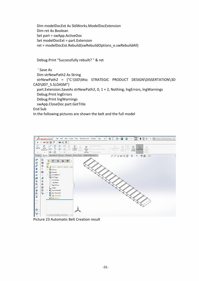
Dim modelDocExt As SldWorks.ModelDocExtension Dim ret As Boolean Set part = swApp.ActiveDoc Set modelDocExt = part.Extension ret = modelDocExt.Rebuild(swRebuildOptions_e.swRebuildAll) Debug.Print "Successfully rebuilt? " & ret ' Save As Dim strNewPath2 As String strNewPath2 = ("C:\SID\Msc STRATEGIC PRODUCT DESIGN\DISSERTATION\3D CAD\007_5.SLDASM") part.Extension.SaveAs strNewPath2, 0, 1 + 2, Nothing, lngErrors, lngWarnings Debug.Print lngErrors Debug.Print lngWarnings swApp.CloseDoc part.GetTitle End Sub In the following pictures are shown the belt and the full model
Picture 23 Automatic Belt Creation result

-32-
Picture 24 locate the belt in the Assembly and create the final model
PACK AND GO AND BILL OF MATERIALS
After the succesful creation of the belt the next step is to save all the parts of the assembly in the final model folder and in same folder must saved a bill of materials as an .xls file for further processing. With clicking in PACK AND GO button a browse window appears and the user selects the model folder that is created later.Then the code runs and saves all the parts and subassemblies in the final model folder and creates the .xls BOM. The code for browsing window (CADSharp video tutorials) is as follows #End If Private Const BIF_RETURNONLYFSDIRS = &H1 Public Function BrowseFolder(szDialogTitle As String) As String Dim szPath As String, wPos As Integer With bi .hOwner = hWndAccessApp .lpszTitle = szDialogTitle .ulFlags = BIF_RETURNONLYFSDIRS End With dwIList = SHBrowseForFolder(bi) szPath = Space$(512) X = SHGetPathFromIDList(ByVal dwIList, ByVal szPath) If X Then wPos = InStr(szPath, Chr(0))

-33-
BrowseFolder = Left$(szPath, wPos - 1) Else BrowseFolder = vbNullString End If End Function The code for the PACK AND GO AND BOM is as follows: Private Sub CommandButton3_Click() 'Option Explicit Dim swapp As SldWorks.SldWorks Dim swModelDoc As SldWorks.ModelDoc2 Dim swModelDocExt As SldWorks.ModelDocExtension Dim swPackAndGo As SldWorks.PackAndGo Dim openFile As String Dim pgFileNames As Variant Dim pgFileStatus As Variant Dim pgGetFileNames As Variant Dim pgDocumentStatus As Variant Dim status As Boolean Dim warnings As Long Dim errors As Long Dim i As Long Dim namesCount As Long Dim myPath As String Dim statuses As Variant Dim strFolder As String Dim strFile As Variant 'Sub main() Set swapp = Application.SldWorks 'Browse for folder strFolder = BrowseFolder("") & "\" Debug.Print strFolder TxtLocation.Text = strFolder ' Open assembly openFile = "C:\SID\Msc STRATEGIC PRODUCT DESIGN\DISSERTATION\3D CAD\007_5.sldasm" Set swModelDoc = swapp.OpenDoc6(openFile, swDocASSEMBLY, swOpenDocOptions_Silent, "", errors, warnings) Set swModelDocExt = swModelDoc.Extension ' Get Pack and Go object

-34-
Debug.Print "Pack and Go" Set swPackAndGo = swModelDocExt.GetPackAndGo ' Get number of documents in assembly namesCount = swPackAndGo.GetDocumentNamesCount Debug.Print " Number of model documents: " & namesCount ' Include any drawings, SOLIDWORKS Simulation results, and SOLIDWORKS Toolbox components swPackAndGo.IncludeDrawings = False Debug.Print " Include drawings: " & swPackAndGo.IncludeDrawings swPackAndGo.IncludeSimulationResults = False Debug.Print " Include SOLIDWORKS Simulation results: " & swPackAndGo.IncludeSimulationResults swPackAndGo.IncludeToolboxComponents = True Debug.Print " Include SOLIDWORKS Toolbox components: " & swPackAndGo.IncludeToolboxComponents ' Get current paths and filenames of the assembly's documents status = swPackAndGo.GetDocumentNames(pgFileNames) Debug.Print "" Debug.Print " Current path and filenames: " If (Not (IsEmpty(pgFileNames))) Then For i = 0 To UBound(pgFileNames) Debug.Print " The path and filename is: " & pgFileNames(i) Next i End If ' Get current save-to paths and filenames of the assembly's documents status = swPackAndGo.GetDocumentSaveToNames(pgFileNames, pgFileStatus) Debug.Print "" Debug.Print " Current default save-to filenames: " If (Not (IsEmpty(pgFileNames))) Then For i = 0 To UBound(pgFileNames) Debug.Print " The path and filename is: " & pgFileNames(i) Next i End If ' Set folder where to save the files myPath = (strFolder) status = swPackAndGo.SetSaveToName(True, myPath) ' Flatten the Pack and Go folder structure; save all files to the root directory swPackAndGo.FlattenToSingleFolder = True

-35-
' Add a prefix and suffix to the new Pack and Go filenames swPackAndGo.AddPrefix = "GEL" swPackAndGo.AddSuffix = "01" ' Verify document paths and filenames after adding prefix and suffix ReDim pgGetFileNames(namesCount - 1) ReDim pgDocumentStatus(namesCount - 1) status = swPackAndGo.GetDocumentSaveToNames(pgGetFileNames, pgDocumentStatus) Debug.Print "" Debug.Print " My Pack and Go path and filenames after adding prefix and suffix: " For i = 0 To (namesCount - 1) Debug.Print " My path and filename is: " & pgGetFileNames(i) Next i ' Pack and Go statuses = swModelDocExt.SavePackAndGo(swPackAndGo) swapp.CloseDoc swModelDoc.GetTitle Dim swModel2 As SldWorks.ModelDoc2 Dim swBOMTable As SldWorks.BomTableAnnotation Dim swTable As SldWorks.TableAnnotation Dim swAnn As SldWorks.Annotation Const BOMTemplate As String = "C:\Program Files\SolidWorks Corp\SolidWorks\lang\english\bom-weight.sldbomtbt" Dim OutputPath As String Dim ConfigName As String ' Open assembly OutputPath = TxtLocation.Text & "\GEL007_501.sldasm" openFile = OutputPath Set swModelDoc = swapp.OpenDoc6(openFile, swDocASSEMBLY, swOpenDocOptions_Silent, "", errors, warnings) Set swModelDocExt = swModelDoc.Extension 'Create XLS BOM Set swapp = Application.SldWorks Set swModel2 = swapp.ActiveDoc ConfigName = swModel2.GetActiveConfiguration.Name Set swBOMTable = swModel2.Extension.InsertBomTable(BOMTemplate, 0, 0, swBomType_e.swBomType_PartsOnly, ConfigName) Set swTable = swBOMTable swTable.SaveAsText OutputPath & "BOMTable_" & txtFolderName.Text & ".xls", vbTab Set swAnn = swTable.GetAnnotation swAnn.Select3 False, Nothing swModel2.EditDelete

-36-
swModel2.ForceRebuild3 True swapp.CloseDoc swModelDoc.GetTitle End Sub The Excel .xls file that is created is the GEL007_501.sldasmBOMTable_GEL360032.xls and contains the following data: ITEM NO. PART NUMBER DESCRIPTION WEIGHT QTY.
1 GEL00301 17108.52 1
2 GEL00001 10963.31 1
3 GEL00001 10935.61 1
4 GEL00401 55.83 2
5 GEL00501 150.91 1
6 GEL00601 264.00 1
7 GEL00801 1465.19 1
8 GEL00701 19478.83 1
9 GEL00901 8596.40 1
10 GEL01101 215.74 1
11 GEL01201 90.48 1
12 GEL01401 98.96 2
13 GEL01501 23.06 2
14 GEL01301 114.93 1
15 GEL01001 508.45 1
16 GEL01601 52.80 2
17 GEL01701 313.83 1
18 GEL01901 3888.62 1
19 GEL01801 691.70 1
20 GEL03001 530.60 2
21 GEL03201 1524.69 2
22 GEL03101 1940.25 1
23 GEL06801 4775.40 1
24 GEL06901 4775.43 1
25 GEL067_101 8226.62 1
26 ISO 7380 - M8 x 10 - 10N 6
27 ISO - 8673 - M8 x 1.0 - W - N 6
28 ISO 7380 - M6 x 10 - 10N 3
29 ISO 10642 - M6 x 8 - 8N 8
30 ISO 1207 - M6 x 8 - 8N 3
31 ISO 4162 - M8 x 25 x 25-N 1
32 GEL02001 50518.15 1
33 GEL02201 34880.74 1
34 GEL021_101 22229.50 1
35 GEL023_101 15347.53 1

-37-
36 GEL04601 11558.66 1
37 GEL04701 11559.74 1
38 GEL05201 5718.62 1
39 GEL04901 12187.49 1
40 GEL05001 9719.48 1
41 GEL04801 1153.04 2
42 GEL05101 3226.14 1
43 GEL05301 1475.11 1
44 GEL06101 311.64 2
45 GEL06201 49.10 8
46 GEL05501 1050.94 2
47 GEL05601 332.16 2
48 GEL06001 29.92 8
49 GEL05901 208.78 2
50 GEL05701 195.44 2
51 GEL05801 Hexagon nuts, style 2 - Product grades A and B 2
52 GEL06301 9477.36 1
53 GEL05401 3981.73 1
54 GEL06601 8017.57 1
55 GEL064_201 4.66 78
56 GEL064_301 7.33 78
57 GEL064_101 6.11 156
58 ISO 4162 - M10 x 20 x 20-N 2
59 ISO 4014 - M10 x 80 x 26-N 4
60 ISO - 4034 - M10 - N 36
61 ISO 4162 - M6 x 12 x 12-N 12
62 ISO 4017 - M10 x 20-N 6
63 GEL010.0101 23919.21 1
64 GEL010.0401 5168.25 1
65 GEL010.0301 831.96 1
66 GEL010.1001 6020.23 1
67 GEL010.0701 19196.13 1
68 GEL010.0801 339.97 1
69 GEL010.0901 2306.41 1
70 GEL010.1101 5709.23 1
71 GEL010.0601 266.22 1
72 GEL010.0201 511.14 1
73 GEL010.0501 545.34 1
74 GEL04501 7774.61 2
75 GEL025_101 55709.36 1
76 GEL02601 850.72 4
77 GEL02701 1227.39 2

-38-
78 GEL02801 338.36 10
79 GEL02901 1457.30 4
80 ISO 4017 - M10 x 25-N 16
81 ISO 4014 - M16 x 100 x 38-N 2
82 ISO - 4034 - M16 - N 4
83 GEL04001 6594.62 2
84 GEL03901 2630.40 2
85 GEL03301 1658.55 1
86 GEL04401 86.60 1
87 GEL03701 882.22 1
88 GEL03501 167.04 3
89 GEL03401 1275.71 1
90 GEL04301 7121.61 1
91 GEL04101 6476.27 2
92 GEL04201 2531.05 1
93 GEL03601 1236.03 1
94 ISO 7412 - M16 x 85 --- 31-WN 2
95 GEL065.0101 1
In a second from Excel we can have the mass of all parts and the number of parts of the assembly which is 549 parts including bolts.
-39-
DRAWING AUTOMATION
Clicking the CREATE DRAWINGS command button runs a code that creates five drawings.
1) First a full Assembly drawing with Bill of Materials for Top level parts and autoballon for the main assemby parts.
The code for the first drawing is: Private Sub CommandButton2_Click() Const strFormatPath As String = "C:\ProgramData\SOLIDWORKS\SOLIDWORKS 2018\lang\english\sheetformat\A3SHEETFORMATSID.slddrt" Const strBOMTemplatePath As String = "C:\Program Files\SolidWorks Corp\SolidWorks\lang\english\bom-standard.sldbomtbt" Const WeldmentTableTemplate As String = "C:\Program Files\SOLIDWORKS Corp\SOLIDWORKS\lang\english\cut list.sldwldtbt" Dim swapp As SldWorks.SldWorks Dim swModel As SldWorks.ModelDoc2 Dim swDraw As SldWorks.DrawingDoc Dim strPath As String Dim vComps As Variant Set swapp = Application.SldWorks 'Create new drawing Dim strTemplatePath As String strTemplatePath = swapp.GetUserPreferenceStringValue(swUserPreferenceStringValue_e.swDefaultTemplateDrawing) Set swModel = swapp.NewDocument(strTemplatePath, swDwgPapersUserDefined, 0.42, 0.297) Set swDraw = swModel Dim strFolder As String strFolder = Left(TxtLocation.Text, InStrRev(TxtLocation.Text, "\")) 'Setup sheet format swDraw.SetupSheet5 "Sheet1", 12, 12, 1, 4, False, strFormatPath, 0.42, 0.297, "Default", True 'Add a new Sheet swDraw.NewSheet3 "Sheet2", 12, 12, 1, 1, False, strFormatPath, 0.42, 0.297, "Default" 'Add a new Sheet swDraw.NewSheet3 "Sheet3", 12, 12, 1, 1, False, strFormatPath, 0.42, 0.297, "Default" 'Add a new Sheet swDraw.NewSheet3 "Sheet4", 12, 12, 1, 1, False, strFormatPath, 0.42, 0.297, "Default" 'Add a new Sheet

-40-
swDraw.NewSheet3 "Sheet5", 12, 12, 1, 1, False, strFormatPath, 0.42, 0.297, "Default" 'Change name of sheets Dim swSheet As SldWorks.Sheet Dim vSheetNames As Variant Dim i As Integer vSheetNames = swDraw.GetSheetNames For i = 0 To UBound(vSheetNames) Set swSheet = swDraw.Sheet(vSheetNames(i)) If i = 0 Then swSheet.SetName "007_5f" If i = 1 Then swSheet.SetName "025" If i = 2 Then swSheet.SetName "021" If i = 3 Then swSheet.SetName "023" If i = 4 Then swSheet.SetName "065" Next i 'Activate first sheet vSheetNames = swDraw.GetSheetNames swDraw.ActivateSheet vSheetNames(0) 'Add isometric view of assembly on first sheet Dim swView As SldWorks.view Dim swIsoView As SldWorks.view Set swView = swDraw.CreateDrawViewFromModelView3(strFolder & "GEL007_501.SLDASM", "*Isometric", 0.14, 0.16, 0) Set swIsoView = swView swDraw.ViewDisplayShaded 'Change view scale to 1:25 Dim dblScale(1) As Double dblScale(0) = 1 dblScale(1) = 25 swView.ScaleRatio = dblScale 'Add BOM to first sheet Dim swBOMAnn As SldWorks.BomTableAnnotation Set swBOMAnn = swIsoView.InsertBomTable3(False, 0.4, 0.25, swBOMConfigurationAnchor_TopRight, swBomType_TopLevelOnly, "Default", strBOMTemplatePath, False) 'Change BOM column to reference Part No custom property swBOMAnn.SetColumnCustomProperty 2, "weight" 'Change BOM column name and column widths Dim swTableAnn As SldWorks.TableAnnotation Set swTableAnn = swBOMAnn
-41-
swTableAnn.Text(0, 2) = "MASS" swTableAnn.SetColumnWidth 1, 0.04, swTableRowColChange_TableSizeCanChange swTableAnn.SetColumnWidth 2, 0.03, swTableRowColChange_TableSizeCanChange 'Rebuild swModel.ForceRebuild3 True 'Create Auto baloon Set swModel = swapp.ActiveDoc Dim vNotes As Variant Dim boolstatus As Boolean Dim autoballoonParams As SldWorks.AutoBalloonOptions boolstatus = swModel.ActivateView("Drawing View1") boolstatus = swModel.Extension.SelectByID2("Drawing View1", "DRAWINGVIEW", 0, 0, 0, False, 0, Nothing, 0) boolstatus = swView.SetKeepLinkedToBOM(True, "Bill of Materials1") Set autoballoonParams = swModel.CreateAutoBalloonOptions() autoballoonParams.Layout = swDetailingBalloonLayout_Left autoballoonParams.ReverseDirection = False autoballoonParams.IgnoreMultiple = True autoballoonParams.InsertMagneticLine = False autoballoonParams.LeaderAttachmentToFaces = True autoballoonParams.Style = swBS_Circular autoballoonParams.Size = swBF_3Chars autoballoonParams.UpperTextContent = swBalloonTextItemNumber autoballoonParams.Layername = "-None-" autoballoonParams.ItemNumberStart = 1 autoballoonParams.ItemNumberIncrement = 1 autoballoonParams.ItemOrder = swBalloonItemNumbers_DoNotChangeItemNumbers autoballoonParams.EditBalloons = True autoballoonParams.EditBalloonOption = swEditBalloonOption_Resequence vNotes = swModel.AutoBalloon5(autoballoonParams) 'Rebuild swModel.ForceRebuild3 True In the following picture is shown the final drawing created automatically in seconds.

-42-
Picture 25.Final Assembly Drawing The following four drawings are for the changed parts in the assemblly. 2)The GEL025.0101 base weldment part. In the drawing a cut list with all parts of the weldment is presented with balloons for all weldment subparts. The code for this drawing automation is: 'Activate second sheet swDraw.ActivateSheet vSheetNames(1) Dim str025Path As String str025Path = strFolder & "GEL025_101.sldprt" 'Add isometric view of assembly on second sheet Set swView = swDraw.CreateDrawViewFromModelView3(str025Path, "*Isometric", 0.14, 0.16, 0) Set swIsoView = swView

-43-
swDraw.ViewDisplayShaded 'Dim swapp As SldWorks.SldWorks Dim oDrawing As DrawingDoc 'Dim swView As View Dim WMTable As SldWorks.WeldmentCutListAnnotation Set swapp = Application.SldWorks Set oDrawing = swapp.ActiveDoc Set swView = oDrawing.GetFirstView Set swView = swView.GetNextView ' Insert the weldment cut list table Set WMTable = swView.InsertWeldmentTable(False, 0.1996662889191, 0.285, swBOMConfigurationAnchor_TopLeft, "Default<As Welded>", WeldmentTableTemplate) 'Dim autoballoonParams As SldWorks.AutoBalloonOptions boolstatus = swModel.ActivateView("Drawing View2") boolstatus = swModel.Extension.SelectByID2("Drawing View2", "DRAWINGVIEW", 0, 0, 0, False, 0, Nothing, 0) boolstatus = swView.SetKeepLinkedToBOM(True, "Weldment Cut List1") Set autoballoonParams = swModel.CreateAutoBalloonOptions() autoballoonParams.Layout = swDetailingBalloonLayout_Left autoballoonParams.ReverseDirection = False autoballoonParams.IgnoreMultiple = True autoballoonParams.InsertMagneticLine = False autoballoonParams.LeaderAttachmentToFaces = True autoballoonParams.Style = swBS_Circular autoballoonParams.Size = swBF_3Chars autoballoonParams.UpperTextContent = swBalloonTextItemNumber autoballoonParams.Layername = "-None-" autoballoonParams.ItemNumberStart = 1 autoballoonParams.ItemNumberIncrement = 1 autoballoonParams.ItemOrder = swBalloonItemNumbers_DoNotChangeItemNumbers autoballoonParams.EditBalloons = True autoballoonParams.EditBalloonOption = swEditBalloonOption_Resequence vNotes = swModel.AutoBalloon5(autoballoonParams) In the following picture is shown the drawing result

-44-
Picture 26.Weldment Part Drawing
3)The changed belt support Drawing The code for this part creation is the following:
'Activate third sheet swDraw.ActivateSheet vSheetNames(2) Dim str021Path As String str021Path = strFolder & "GEL021_101.sldprt" 'Add flatpattern view of 021part on third sheet Set swView = swDraw.CreateFlatPatternViewFromModelView3(str021Path, "",
0.12, 0.22, 0, False, True) swDraw.ChangeRefConfigurationOfFlatPatternView str021Path, "021_3SM-
FLAT-PATTERN" boolstatus = swDraw.ShowConfiguration2("021_3SM-FLAT-PATTERN") swView.ScaleDecimal = swView.ScaleDecimal / 8# boolstatus = swDraw.Extension.SelectByID2("Drawing View3",
"DRAWINGVIEW", 0.173216155013913, 0.315983290823776, 0, False, 0, Nothing, 0)
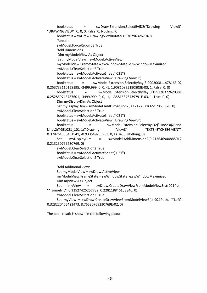
-45-
boolstatus = swDraw.Extension.SelectByID2("Drawing View3", "DRAWINGVIEW", 0, 0, 0, False, 0, Nothing, 0)
boolstatus = swDraw.DrawingViewRotate(1.5707963267949) 'Rebuild swModel.ForceRebuild3 True 'Add Dimensions Dim myModelView As Object Set myModelView = swModel.ActiveView myModelView.FrameState = swWindowState_e.swWindowMaximized swModel.ClearSelection2 True boolstatus = swModel.ActivateSheet("021") boolstatus = swModel.ActivateView("Drawing View3") boolstatus = swModel.Extension.SelectByRay(3.99030081147816E-02,
0.253733110158195, -3499.999, 0, 0, -1, 1.90810825190803E-03, 1, False, 0, 0) boolstatus = swModel.Extension.SelectByRay(0.199220372620381,
0.252859743787601, -3499.999, 0, 0, -1, 1.35815376439791E-03, 1, True, 0, 0) Dim myDisplayDim As Object Set myDisplayDim = swModel.AddDimension2(0.121725716651795, 0.28, 0) swModel.ClearSelection2 True boolstatus = swModel.ActivateSheet("021") boolstatus = swModel.ActivateView("Drawing View3") boolstatus = swModel.Extension.SelectByID2("Line23@Bend-
Lines2@GEL021_101-1@Drawing View3", "EXTSKETCHSEGMENT", 0.378261538461541, -0.933549236983, 0, False, 0, Nothing, 0)
Set myDisplayDim = swModel.AddDimension2(0.213646944885012, 0.213230769230769, 0)
swModel.ClearSelection2 True boolstatus = swModel.ActivateSheet("021") swModel.ClearSelection2 True 'Add Additional views Set myModelView = swDraw.ActiveView myModelView.FrameState = swWindowState_e.swWindowMaximized Dim myView As Object Set myView = swDraw.CreateDrawViewFromModelView3(str021Path,
"*Isometric", 0.31527425257732, 0.228118846153846, 0) swModel.ClearSelection2 True Set myView = swDraw.CreateDrawViewFromModelView3(str021Path, "*Left",
0.328220406423473, 8.76530769230769E-02, 0) The code result is shown in the following picture:

-46-
Picture 27.Sheet metal part belt support drawing

-47-
4)The second changed part belt support drawing. The code for this drawing is as follows: 'Activate fourth sheet swDraw.ActivateSheet vSheetNames(3) Dim str023Path As String str023Path = strFolder & "GEL023_101.sldprt" 'Add flatpattern view of 021part on third sheet Set swView = swDraw.CreateFlatPatternViewFromModelView3(str023Path, "", 0.12, 0.22, 0, False, True) swDraw.ChangeRefConfigurationOfFlatPatternView str023Path, "023_3SM-FLAT-PATTERN" boolstatus = swDraw.ShowConfiguration2("023_3SM-FLAT-PATTERN") swView.ScaleDecimal = swView.ScaleDecimal / 8# boolstatus = swDraw.Extension.SelectByID2("Drawing View6", "DRAWINGVIEW", 0.173216155013913, 0.315983290823776, 0, False, 0, Nothing, 0) boolstatus = swDraw.Extension.SelectByID2("Drawing View6", "DRAWINGVIEW", 0, 0, 0, False, 0, Nothing, 0) boolstatus = swDraw.DrawingViewRotate(1.5707963267949) 'Rebuild swModel.ForceRebuild3 True 'Add Dimensions Set myModelView = swModel.ActiveView myModelView.FrameState = swWindowState_e.swWindowMaximized swModel.ClearSelection2 True boolstatus = swModel.ActivateSheet("023") boolstatus = swModel.ActivateView("Drawing View6") boolstatus = swModel.Extension.SelectByID2("Line8@Bend-Lines2@GEL023_101-1@Drawing View6", "EXTSKETCHSEGMENT", 0.140296318918609, 0.407381967351668, 0, False, 0, Nothing, 0) 'Dim myDisplayDim As Object Set myDisplayDim = swModel.AddDimension2(0.117759751902909, 0.281907259303189, 0) swModel.ClearSelection2 True boolstatus = swModel.ActivateSheet("023") boolstatus = swModel.ActivateView("Drawing View6") boolstatus = swModel.Extension.SelectByRay(0.155760661909792, 0.164822116056189, -3499.999, 0, 0, -1, 2.30302358338915E-03, 1, False, 0, 0) boolstatus = swModel.Extension.SelectByRay(0.15372858227739, 0.275909135960842, -3499.999, 0, 0, -1, 2.30302358338915E-03, 1, True, 0, 0) Set myDisplayDim = swModel.AddDimension2(0.205885292842379, 0.215624106890684, 0) swModel.ClearSelection2 True boolstatus = swModel.ActivateSheet("023") swModel.ClearSelection2 True

-48-
'Add Additional views Set myModelView = swDraw.ActiveView myModelView.FrameState = swWindowState_e.swWindowMaximized 'Dim myView As Object Set myView = swDraw.CreateDrawViewFromModelView3(str023Path, "*Isometric", 0.31527425257732, 0.228118846153846, 0) swModel.ClearSelection2 True Set myView = swDraw.CreateDrawViewFromModelView3(str023Path, "*Left", 0.328220406423473, 8.76530769230769E-02, 0) The final drawing is shown in the following picture:
Picture 28.Second sheet metal part belt support drawing drawing

-49-
4)The belt drawing.This part is created automatically from scratch with API. The code for this drawing is as follows: 'Activate fifth sheet swDraw.ActivateSheet vSheetNames(4) Dim str065Path As String str065Path = strFolder & "GEL065.0101.sldprt" swDraw.Create3rdAngleViews2 str065Path ' Get sheet size Dim cursheet As Sheet Dim sheetwidth As Double, sheetheight As Double Set cursheet = swDraw.GetCurrentSheet cursheet.GetSize sheetwidth, sheetheight Dim view As view Dim vOutline As Variant, vPosition As Variant Dim viewWidth As Double, viewHeight As Double Set view = swDraw.CreateDrawViewFromModelView3(str065Path, "*Isometric", sheetwidth, sheetheight, 0) ' Now get view size and move left and down to bring into sheet vOutline = view.GetOutline vPosition = view.Position viewWidth = vOutline(2) - vOutline(0) viewHeight = vOutline(3) - vOutline(1) vPosition(0) = vPosition(0) - viewWidth vPosition(1) = vPosition(1) - viewHeight view.Position = vPosition ' Insert model dimensions Dim v As view Set v = swDraw.GetFirstView ' Sheet Set v = v.GetNextView ' First view swDraw.ClearSelection2 True While Not v Is Nothing If v.Name <> view.Name Then swDraw.Extension.SelectByID2 v.Name, "DRAWINGVIEW", 0, 0, 0, True, -1, Nothing, 0 Set v = v.GetNextView Wend swDraw.InsertModelAnnotations3 0, 327663, True, True, False, False 'Save drawing

-50-
swModel.Extension.SaveAs strFolder & "007_5final.SLDDRW", swSaveAsCurrentVersion, 1, _ Nothing, Empty, Empty The created drawing is shown in the following picture:
Picture 29.Belt Drawing

-51-
Conclusions
The effort to design automation with using solidworks API is proved a competitive task and it demands a lot of code learning and implementation ,a lot of try and error efforts a lot of reading and patience. Solidworks API programming consists of creating variables , assigning values or references to those variables and finally using the variables to have the desired result. As CADSharp refers to a tutorial video :” as of Solidworks 2012,the Solidworks API has 383 Interfaces,273 event notifications and a conservative estimate of 10000+ members. If someone some months ago allegates that have an automation tool that creates in about an hour 105 machine models with different dimensions and with 57645 total parts I would suppose that he is a magician. The truth is that the avocation with VBA and API is like magic and like the automating result it automatically changes the way of design implementation.


-53-
Bibliography
1.Parametric modeling with Solidworks 2015, [Paul_Schilling,_Randy_Shih],SDC
Publications 2015
2.Mastering Solidworks, Matt Lombart, Copyright © 2019 by John Wiley & Sons,
Inc., Indianapolis, Indiana
3.Automating SolidWorks 2011 Using Macros, Mike Spens, Schroff Development
Corporation,2010
4.Solidworks 2008 API Programming and Automation ,Luke Malpass
,Angelsix.com,2008 ,Second Edition
5.Solidworks 2009 API,Advanced Product development, Luke Malpass,
Angelsix.com,2008 ,Second Edition
6.Visual Basic and Visual Basic Net for Scientists and Engineers, Christopher
M.Frenz.
7.Habasit Conveyor Belts Engineering Guide.
WEB SOURCES:
1)https://www.cadsharp.com Solidworks API and PDM API Training and Services
2019
2) http://www.angelsix.com/solidworks Automation software , macros and add ins
for Solidworks.2019
3).https://help.solidworks.com/2019/English/api/sldworksapiprogguide
Solidworks API Help 2019
4).https://my.solidworks.com/training/elearning/68/api-fundamentals 2019
Articles:
1)Towards modeling of assemblies for product design, Rajneet Sodhi and Joshua U
Turner,1994 Butter worth Heinemann Ltd
2)Functional understanding of Assembly Modelling Jin-Kang Gui and Martti
Mäntylä, 1994 Butter worth Heinemann Ltd
3)Automated Tool Selection for Computer-Aided Process Planning in Sheet Metal
Bending, J. R. Duflou’ (2), T. H. M. Nguyen’, J.-P. Kruth’ ( I ) , D. Cattrysse2, Department
of Mechanical Engineering, Centre for Industrial Management, Katholieke Universiteit
Leuven, Celestijnenlaan 300, 3001 Leuven, Belgium.

-54-
5)Intelligent dimensioning of Mechanical parts based on feature extraction,Ke-
Zhang Chen,Xin An Feng,Quan-Sheng Lu,Department of Mechanical Engineering ,The
University of Hong-Kong,31 August 2000.
6)Intelligent aproaches for generating assembly drawings from 3-D computer
models of mechanical parts, Ke-Zhang Chen,Xin An Feng,Lan Ding,Department of
Mechanical Engineering ,The University of Hong-Kong,31 February 2001.

-55-
-1-
Appendix
MODEL AUTOMATION VBA CODE. 'MODEL AUTOMATION MACRO Created by Sideris Vougioukakis for IHU Strategic Product Design Dissertation PROJECT 'The Macro has the Ability to create 17x6=102 different models with all subassemblies and parts 'The Macro Automatically creates a specific folder for each model and extracts a Bill of Materials as an .xls file. 'The Macro creates automatically a final assembly drawing with BOM and four drawings for the changeable parts. 'Option Explicit Public swapp As SldWorks.SldWorks Public swModel As SldWorks.ModelDoc2 Public swModel2 As SldWorks.ModelDoc2 Public swModel3 As SldWorks.ModelDoc2 Public swmodel4 As SldWorks.ModelDoc2 Public swDocSpec As SldWorks.DocumentSpecification Public swDocSpec2 As SldWorks.DocumentSpecification Public swDocSpec3 As SldWorks.DocumentSpecification Public boolstatus As Boolean Public swModelDocExt As SldWorks.ModelDocExtension Public lngErrors As Long Public lngWarnings As Long Public swSketchMgr As SldWorks.SketchManager Public swSketchSeg As SldWorks.SketchSegment Public swselmgr As SldWorks.SelectionMgr Public swFeatMgr As SldWorks.FeatureManager Public swFeat As SldWorks.Feature Public swAssy As SldWorks.AssemblyDoc Public swBaseFlangeFeatData As SldWorks.BaseFlangeFeatureData Const strFullPath As String = "C:\SID\Msc STRATEGIC PRODUCT DESIGN\DISSERTATION\3D CAD\007_4.SLDASM" Const strFullPath2 As String = "C:\SID\Msc STRATEGIC PRODUCT DESIGN\DISSERTATION\3D CAD\021.SLDPRT" Const strFullPath3 As String = "C:\SID\Msc STRATEGIC PRODUCT DESIGN\DISSERTATION\3D CAD\023.SLDPRT" Const strFullPath4 As String = "C:\SID\Msc STRATEGIC PRODUCT DESIGN\DISSERTATION\3D CAD\025_4.SLDPRT" Dim Alength As Integer Private Sub CMDB1_Click()

-2-
' Initial Code Alength = TXTA.Text If Alength < 300 Or Alength > 2000 Then MsgBox "Please ENTER value between 300 and 2000" Exit Sub Else 'Alength > 300 And Alength < 2000 Then MsgBox "Go on" End If 'Modify part 021 Set swapp = Application.SldWorks Set swDocSpec = swapp.GetOpenDocSpec(strFullPath2) Set swModel = swapp.OpenDoc7(swDocSpec) 'modify base flange Set swselmgr = swModel.SelectionManager boolstatus = swModel.Extension.SelectByID2("Base-Flange1", "BODYFEATURE", 0, 0, 0, False, 0, Nothing, 0) 'change the selection Set swFeat = swselmgr.GetSelectedObject6(1, -1) Set swBaseFlange = swFeat.GetDefinition swBaseFlange.AccessSelections swModel, Nothing swBaseFlange.D1OffsetType = 1 swBaseFlange.D1OffsetDistance = ((Int(TXTA.Text / 100) - (TXTA.Text / 100 - Int(TXTA.Text / 100) > 0)) * 100) / 1000 swFeat.ModifyDefinition swBaseFlange, swModel, Nothing Dim strNewPath As String strNewPath = Replace(swModel.GetPathName, "021", "021_1") swModel.ForceRebuild3 False swModel.Extension.SaveAs strNewPath, 0, 1 + 2, Nothing, lngErrors, lngWarnings Debug.Print lngErrors Debug.Print lngWarnings swapp.CloseDoc swModel.GetTitle 'Modify part 023 Set swapp = Application.SldWorks Set swDocSpec2 = swapp.GetOpenDocSpec(strFullPath3) Set swModel2 = swapp.OpenDoc7(swDocSpec2) 'modify base flange Set swselmgr = swModel2.SelectionManager boolstatus = swModel2.Extension.SelectByID2("Base-Flange2", "BODYFEATURE", 0, 0, 0, False, 0, Nothing, 0) 'change the selection Set swFeat = swselmgr.GetSelectedObject6(1, -1) Set swBaseFlange = swFeat.GetDefinition
-3-
swBaseFlange.AccessSelections swModel2, Nothing swBaseFlange.D1OffsetType = 1 swBaseFlange.D1OffsetDistance = ((Int(TXTA.Text / 100) - (TXTA.Text / 100 - Int(TXTA.Text / 100) > 0)) * 100) / 1000 swFeat.ModifyDefinition swBaseFlange, swModel2, Nothing Dim strNewPath2 As String strNewPath2 = Replace(swModel2.GetPathName, "023", "023_1") swModel2.ForceRebuild3 False swModel2.Extension.SaveAs strNewPath2, 0, 1 + 2, Nothing, lngErrors, lngWarnings Debug.Print lngErrors Debug.Print lngWarnings swapp.CloseDoc swModel2.GetTitle 'Add Base Component 003 Set swapp = Application.SldWorks Set swDocSpec3 = swapp.GetOpenDocSpec(strFullPath4) Set swModel3 = swapp.OpenDoc7(swDocSpec3) Set swModel3 = swapp.ActiveDoc boolstatus = swModel3.Extension.SelectByID2("D6@Sketch1@025_4.SLDPRT", "DIMENSION", -0.848360208743701, -6.10458090746218E-02, -2.59187069932285, False, 0, Nothing, 0) Dim myDimension As Object Set myDimension = swModel3.Parameter("D6@Sketch1@025_4.Part") myDimension.SystemValue = ((Int(TXTA.Text / 50) - (TXTA.Text / 50 - Int(TXTA.Text / 50) > 0)) * 50) / 2000 swModel3.ClearSelection2 True boolstatus = swModel3.EditRebuild3() 'Save new base part Dim strNewPath3 As String strNewPath3 = Replace(swModel3.GetPathName, "025_4", "025_1") swModel3.Extension.SaveAs strNewPath3, 0, 1 + 2, Nothing, lngErrors, lngWarnings Debug.Print lngErrors Debug.Print lngWarnings swModel3.ClearSelection2 True swModel3.ForceRebuild3 False swapp.CloseDoc swModel3.GetTitle 'Open assembly 007_4 Set swapp = Application.SldWorks Set swDocSpec = swapp.GetOpenDocSpec(strFullPath) Set swModel = swapp.OpenDoc7(swDocSpec) swModel.ForceRebuild3 True boolstatus = swModel.Extension.SelectByID2("003_3-1@007_4", "COMPONENT", 0, 0, 0, False, 0, Nothing, 0) swModel.EditAssembly swModel.ClearSelection2 True

-4-
boolstatus = swModel.Extension.SelectByID2("003_3-1@007_4/025_1-1@003_3", "COMPONENT", 0, 0, 0, False, 0, Nothing, 0) swModel.EditPart swModel.ClearSelection2 True boolstatus = swModel.Extension.SelectByID2("Sketch1@003_3-1@007_4/025_1-1@003_3", "SKETCH", 0, 0, 0, False, 0, Nothing, 0) swModel.EditSketch swModel.ClearSelection2 True boolstatus = swModel.Extension.SelectByID2("Sketch1@003_3-1@007_4/025_1-1@003_3", "SKETCH", 0, 0, 0, False, 0, Nothing, 0) swModel.ClearSelection2 True swModel.SketchManager.InsertSketch True swModel.ClearSelection2 True swModel.AssemblyPartToggle swModel.EditAssembly 'Modify inclination Set swapp = Application.SldWorks Set model = swapp.ActiveDoc boolstatus = swModel.Extension.SelectByID2("Top Plane@020-1@007_4", "PLANE", 0, 0, 0, True, 1, Nothing, 0) boolstatus = swModel.Extension.SelectByID2("PLANEAM1@003_3-1@007_4", "PLANE", 0, 0, 0, True, 1, Nothing, 0) ' Redraw swModel.GraphicsRedraw2 ' Mate Dim swMate As Mate2 ' Create AngleMateFeatureData Dim MateData As AngleMateFeatureData Set MateData = swModel.CreateMateData(6) ' Set the Entities To Mate Dim EntitiesToMate(1) As Object Set EntitiesToMate(0) = swModel.SelectionManager.GetSelectedObject6(1, -1) Set EntitiesToMate(1) = swModel.SelectionManager.GetSelectedObject6(2, -1) Dim EntitiesToMateVar As Variant EntitiesToMateVar = EntitiesToMate MateData.EntitiesToMate = (EntitiesToMateVar) ' Set the Mate Alignment MateData.MateAlignment = 0 ' Set the Limit Angles If Optb32.Value = True Then MateData.Angle = 0.558505360638187 If Optb33.Value = True Then MateData.Angle = 0.575958653158129

-5-
If Optb34.Value = True Then MateData.Angle = 0.593411945678072 If Optb35.Value = True Then MateData.Angle = 0.610865238198015 If Optb36.Value = True Then MateData.Angle = 0.628318530717959 If Optb37.Value = True Then MateData.Angle = 0.645771823237902 'If Optb38.Value = True Then MateData.Angle = 0.663225115757845 MateData.MaximumAngle = 0.663225115757847 MateData.MinimumAngle = 0.558505360638187 ' Set the Flip Dimension MateData.FlipDimension = False ' Create the mate Dim MateFeature As Feature Set MateFeature = swModel.CreateMate(MateData) swModel.ClearSelection2 True swModel.EditRebuild3 swModel.ForceRebuild3 True strNewPath3 = Replace(swModel.GetPathName, "007_4", "007_6") swModel.Extension.SaveAs strNewPath3, 0, 1 + 2, Nothing, lngErrors, lngWarnings Debug.Print lngErrors Debug.Print lngWarnings swModel.ForceRebuild3 False swapp.CloseDoc swModel.GetTitle 'Create model folder Dim strFname As String Dim strFnameA As String Dim strFnameB As String Dim strFnameC As String strFnameA = "GEL" strFnameB = 2500 + ((Int(TXTA.Text / 100) - (TXTA.Text / 100 - Int(TXTA.Text / 100) > 0)) * 100) If Optb32.Value = True Then strFnameC = 32 If Optb33.Value = True Then strFnameC = 33 If Optb34.Value = True Then strFnameC = 34 If Optb35.Value = True Then strFnameC = 35 If Optb36.Value = True Then strFnameC = 36 If Optb37.Value = True Then strFnameC = 37 strFname = strFnameA & strFnameB & strFnameC Debug.Print strFname txtFolderName.Text = strFname Dim strmodelfolder As String strmodelfolder = "C:\SID\Msc STRATEGIC PRODUCT DESIGN\DISSERTATION\3D CAD\" & strFname MkDir (strmodelfolder)

-6-
End Sub Private Sub CMDB2_Click() End End Sub Private Sub CommandButton1_Click() 'Option Explicit Dim swapp As SldWorks.SldWorks Dim swModel As SldWorks.ModelDoc2 Dim boolstatus As Boolean Dim swModelDocExt As SldWorks.ModelDocExtension Dim swMeasure As SldWorks.Measure Dim lngErrors As Long Dim lngWarnings As Long Dim swSketchMgr As SldWorks.SketchManager Dim swSketchSeg As SldWorks.SketchSegment Dim swFeatMgr As SldWorks.FeatureManager Dim part As Object Dim myFeature As Object Const strFullPath As String = "C:\SID\Msc STRATEGIC PRODUCT DESIGN\DISSERTATION\3D CAD\007_6.SLDASM" Const strTemplate As String = "C:\ProgramData\SolidWorks\SOLIDWORKS 2018\templates\Part.prtdot" 'Sub main() Set swapp = Application.SldWorks Set swModel = swapp.OpenDoc6(strFullPath, swDocASSEMBLY, 1, "", lngErrors, lngWarnings) swModel.ForceRebuild3 True 'select the two axes Set part = swapp.ActiveDoc Set swModelDocExt = swModel.Extension boolstatus = swModel.Extension.SelectByID2("Axis1@000-1@007_6/009-1@000", "AXIS", 0, 0, 0, False, 0, Nothing, 0) boolstatus = swModel.Extension.SelectByID2("Axis2@012-1@007_6/009-1@012/050-1@009", "AXIS", 0, 0, 0, True, 0, Nothing, 0) boolstatus = swModel.Extension.SelectByID2("Axis2@012-1@007_6/009-1@012/050-1@009", "AXIS", 0, 0, 0, False, 0, Nothing, 0) boolstatus = swModel.Extension.SelectByID2("Axis2@012-1@007_6/009-1@012/050-1@009", "AXIS", 0, 0, 0, False, 0, Nothing, 0) 'Measure distance between axes Set swMeasure = swModelDocExt.CreateMeasure

-7-
'Can set this to 0 ' 0 = center to center boolstatus = swMeasure.Calculate(Nothing) If (Not (swMeasure.NormalDistance = -1)) Then Debug.Print "Normal distance: " & swMeasure.NormalDistance End If 'Open new part "conveyor belt" Set swModel = swapp.NewDocument(strTemplate, 0, 0, 0) Set swModel = swapp.ActiveDoc Set swSketchMgr = swModel.SketchManager 'select Front plane and insert sketch swModel.Extension.SelectByID2 "Front Plane", "PLANE", 0, 0, 0, False, 0, Nothing, 0 swSketchMgr.InsertSketch True 'turn on direct addition to database swSketchMgr.AddToDB = True 'create sketch entities Set swSketchSeg = swSketchMgr.CreateCenterLine(0, 0, 0, swMeasure.NormalDistance, 0, 0) Set swSketchSeg = swSketchMgr.CreateArc(0, 0, 0, 0.0005, 0.095, 0, 0.0005, -0.095, 0, 1) Set swSketchSeg = swSketchMgr.CreateLine(0.0005, 0.095, 0, swMeasure.NormalDistance + 0.000377789, 0.0715, 0) Set swSketchSeg = swSketchMgr.CreateArc(swMeasure.NormalDistance, 0, 0, swMeasure.NormalDistance + 0.000377789, -0.0715, 0, swMeasure.NormalDistance + 0.000377789, 0.0715, 0, 1) Set swSketchSeg = swSketchMgr.CreateLine(0.0005, -0.095, 0, swMeasure.NormalDistance + 0.000377789, -0.0715, 0) swModel.ClearSelection2 True Set swModelDocExt = swModel.Extension boolstatus = swModel.Extension.SelectByID2("Arc1", "SKETCHSEGMENT", -8.34190373480239E-02, -4.03973191584217E-02, 0, True, 0, Nothing, 0) boolstatus = swModel.Extension.SelectByID2("Line2", "SKETCHSEGMENT", 1.03894397726365, 6.67946541471873E-02, 0, True, 0, Nothing, 0) boolstatus = swModel.Extension.SelectByID2("Arc2", "SKETCHSEGMENT", 4.31145186818194, -8.87026818618364E-03, 0, True, 0, Nothing, 0) boolstatus = swModel.Extension.SelectByID2("Line3", "SKETCHSEGMENT", 3.78179741184834, -8.45351905195546E-02, 0, True, 0, Nothing, 0) boolstatus = swSketchMgr.SketchOffset2(0.003, False, True, swSkOffsetCapEndType_e.swSkOffsetNoCaps, swSkOffsetMakeConstructionType_e.swSkOffsetDontMakeConstruction, True) 'Fully define sketch swModel.Extension.SelectByID2 "", "EXTSKETCHPOINT", 0, 0, 0, False, 6, Nothing, 0 swSketchMgr.FullyDefineSketch True, True, 1023, True, 1, Nothing, 1, Nothing, 0, 0 'create extrude feature for belt Set swFeatMgr = swModel.FeatureManager
-8-
swFeatMgr.FeatureExtrusion2 True, False, False, 0, 0, 0.6, 0.01, False, False, False, False, 1.74532925199433E-02, 1.74532925199433E-02, False, False, False, False, True, True, True, 0, 0, False swModel.SelectionManager.EnableContourSelection = False 'create belt's flights boolstatus = swModel.Extension.SelectByRay(3.64328870651076, 0.077661359525564, 0.278647649400909, -0.499999999999997, -0.707106781186554, -0.499999999999995, 2.05346553271193E-02, 2, False, 0, 0) swSketchMgr.InsertSketch True Set swSketchSeg = swSketchMgr.CreateLine(0, 0, 0, 0.015, 0, 0) Set swSketchSeg = swSketchMgr.CreateLine(0.015, 0, 0, 0.015, -0.6, 0) Set swSketchSeg = swSketchMgr.CreateLine(0.015, -0.6, 0, 0, -0.6, 0) Set swSketchSeg = swSketchMgr.CreateLine(0, -0.6, 0, 0, 0, 0) swModel.Extension.SelectByID2 "", "EXTSKETCHPOINT", 0, 0, 0, False, 6, Nothing, 0 swSketchMgr.FullyDefineSketch True, True, 1023, True, 1, Nothing, 1, Nothing, 0, 0 'turn off direct addition to database swSketchMgr.AddToDB = False 'create extrude feature for belt Set swFeatMgr = swModel.FeatureManager swFeatMgr.FeatureExtrusion2 True, False, False, 0, 0, 0.06, 0.01, False, False, False, False, 1.74532925199433E-02, 1.74532925199433E-02, False, False, False, False, True, True, True, 0, 0, False swModel.SelectionManager.EnableContourSelection = False swModel.ActivateSelectedFeature boolstatus = swModel.Extension.SelectByRay(4.03114011126439, 7.60216698471936E-02, -7.46493079589072E-04, -0.499999999999997, -0.707106781186554, -0.499999999999995, 1.82180805746601E-03, 1, True, 1, 0) 'Linear pattern Dim swLinearPattern As Feature Set swLinearPattern = swModel.FeatureManager.FeatureLinearPattern5((swMeasure.NormalDistance + 0.15) / 0.3, 0.3, 1, 0.01, True, False, "NULL", "NULL", False, False, False, False, False, False, True, True, False, False, 0, 0, False, False) boolstatus = swModel.Extension.SelectByID2("Top Plane", "PLANE", 0, 0, 0, True, 0, Nothing, 0) swModel.ClearSelection2 True boolstatus = swModel.Extension.SelectByID2("LPattern1", "BODYFEATURE", 0, 0, 0, False, 1, Nothing, 0) boolstatus = swModel.Extension.SelectByID2("Top Plane", "PLANE", 0, 0, 0, True, 2, Nothing, 0) Set myFeature = swModel.FeatureManager.InsertMirrorFeature(False, False, False, False) Debug.Print lngErrors Debug.Print lngWarnings

-9-
boolstatus = swModel.Extension.SelectByID2("Top Plane", "PLANE", 0, 0, 0, True, 0, Nothing, 0) boolstatus = swModel.Extension.SelectByID2("Right Plane", "PLANE", 0, 0, 0, True, 0, Nothing, 0) boolstatus = swModel.InsertAxis2(True) boolstatus = swModel.Extension.SelectByID2("Axis1", "AXIS", 0, 0, 0, False, 0, Nothing, 0) boolstatus = swModel.SelectedFeatureProperties(0, 0, 0, 0, 0, 0, 0, 1, 0, "beltaxis1") swModel.ClearSelection2 True boolstatus = swModel.Extension.SelectByID2("Right Plane", "PLANE", 0, 0, 0, True, 0, Nothing, 0) Dim myRefPlane As Object Set myRefPlane = swModel.FeatureManager.InsertRefPlane(8, swMeasure.NormalDistance, 0, 0, 0, 0) 'swModel.ClearSelection2 True boolstatus = swModel.Extension.SelectByID2("Plane1", "PLANE", 0, 0, 0, False, 0, Nothing, 0) boolstatus = swModel.SelectedFeatureProperties(0, 0, 0, 0, 0, 0, 0, 1, 0, "beltPlane1") swModel.ClearSelection2 True boolstatus = swModel.Extension.SelectByID2("Top Plane", "PLANE", 0, 0, 0, True, 0, Nothing, 0) boolstatus = swModel.Extension.SelectByID2("beltPlane1", "PLANE", 0, 0, 0, True, 0, Nothing, 0) boolstatus = swModel.InsertAxis2(True) boolstatus = swModel.Extension.SelectByID2("Axis2", "AXIS", 0, 0, 0, False, 0, Nothing, 0) boolstatus = swModel.SelectedFeatureProperties(0, 0, 0, 0, 0, 0, 0, 1, 0, "beltaxis2") swModel.SetMaterialPropertyName2 "Default", "C:/Program Files/SOLIDWORKS Corp/SOLIDWORKS/lang/english/sldmaterials/SOLIDWORKS Materials.sldmat", "PVC Rigid" ' Save As Dim strNewPath As String strNewPath = ("C:\SID\Msc STRATEGIC PRODUCT DESIGN\DISSERTATION\3D CAD\BELT\065.01.SLDPRT") swModel.Extension.SaveAs strNewPath, 0, 1 + 2, Nothing, lngErrors, lngWarnings Debug.Print lngErrors Debug.Print lngWarnings swapp.CloseDoc swModel.GetTitle ' Insert Component Dim AssemblyTitle As String AssemblyTitle = "007_6.sldasm" Dim tmpObj As ModelDoc2 Dim errors As Long

-10-
Set tmpObj = swapp.OpenDoc6("C:\SID\Msc STRATEGIC PRODUCT DESIGN\DISSERTATION\3D CAD\BELT\065.01.SLDPRT", 1, 32, "", lngErrors, lngWarnings) Set part = swapp.ActivateDoc3(AssemblyTitle, True, 0, errors) Dim swInsertedComponent As Component2 Set swInsertedComponent = part.AddComponent5("C:\SID\Msc STRATEGIC PRODUCT DESIGN\DISSERTATION\3D CAD\BELT\065.01.SLDPRT", 0, "", False, "", -2.27655580660212, -1.46274679352064, 1.61716853186954) swapp.CloseDoc "C:\SID\Msc STRATEGIC PRODUCT DESIGN\DISSERTATION\3D CAD\BELT\065.01.SLDPRT" Debug.Print lngErrors Debug.Print lngWarnings Set part = swapp.ActiveDoc boolstatus = part.Extension.SelectByID2("Axis2@012-1@007_6/009-1@012/050-1@009", "AXIS", 0, 0, 0, True, 1, Nothing, 0) boolstatus = part.Extension.SelectByID2("[email protected]@007_6", "AXIS", 0, 0, 0, True, 1, Nothing, 0) ' Mate Dim Longstatus As Long Dim swMate As Mate2 Set swMate = part.AddMate5(0, 0, False, 1.2409778849558, 0.001, 0.001, 0.001, 0.001, 0, 0.5235987755983, 0.5235987755983, False, False, 0, Longstatus) part.ClearSelection2 True part.EditRebuild3 boolstatus = part.Extension.SelectByID2("Axis1@000-1@007_6/009-1@000", "AXIS", 0, 0, 0, True, 1, Nothing, 0) boolstatus = part.Extension.SelectByID2("[email protected]@007_6", "AXIS", 0, 0, 0, True, 1, Nothing, 0) ' Mate Set swMate = part.AddMate5(0, 1, False, 1.65264431645537, 0.001, 0.001, 0.001, 0.001, 0, 0.5235987755983, 0.5235987755983, False, False, 0, Longstatus) part.ClearSelection2 True part.EditRebuild3 'Set Part = swApp.ActiveDoc boolstatus = part.Extension.SelectByID2("Front [email protected]@007_6", "PLANE", 0, 0, 0, True, 1, Nothing, 0) boolstatus = part.Extension.SelectByRay(-0.881810075782198, 0.790938530200947, 0.711038661719044, -0.768387446773871, -0.589805937475062, -0.248414346927659, 1.97761346254929E-02, 2, True, 1, 0) ' Mate 'Dim swMate As Mate2
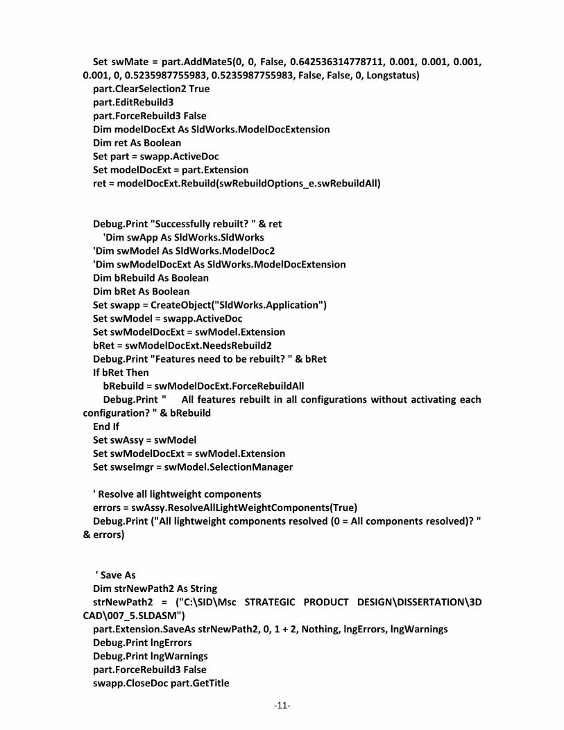
-11-
Set swMate = part.AddMate5(0, 0, False, 0.642536314778711, 0.001, 0.001, 0.001, 0.001, 0, 0.5235987755983, 0.5235987755983, False, False, 0, Longstatus) part.ClearSelection2 True part.EditRebuild3 part.ForceRebuild3 False Dim modelDocExt As SldWorks.ModelDocExtension Dim ret As Boolean Set part = swapp.ActiveDoc Set modelDocExt = part.Extension ret = modelDocExt.Rebuild(swRebuildOptions_e.swRebuildAll) Debug.Print "Successfully rebuilt? " & ret 'Dim swApp As SldWorks.SldWorks 'Dim swModel As SldWorks.ModelDoc2 'Dim swModelDocExt As SldWorks.ModelDocExtension Dim bRebuild As Boolean Dim bRet As Boolean Set swapp = CreateObject("SldWorks.Application") Set swModel = swapp.ActiveDoc Set swModelDocExt = swModel.Extension bRet = swModelDocExt.NeedsRebuild2 Debug.Print "Features need to be rebuilt? " & bRet If bRet Then bRebuild = swModelDocExt.ForceRebuildAll Debug.Print " All features rebuilt in all configurations without activating each configuration? " & bRebuild End If Set swAssy = swModel Set swModelDocExt = swModel.Extension Set swselmgr = swModel.SelectionManager ' Resolve all lightweight components errors = swAssy.ResolveAllLightWeightComponents(True) Debug.Print ("All lightweight components resolved (0 = All components resolved)? " & errors) ' Save As Dim strNewPath2 As String strNewPath2 = ("C:\SID\Msc STRATEGIC PRODUCT DESIGN\DISSERTATION\3D CAD\007_5.SLDASM") part.Extension.SaveAs strNewPath2, 0, 1 + 2, Nothing, lngErrors, lngWarnings Debug.Print lngErrors Debug.Print lngWarnings part.ForceRebuild3 False swapp.CloseDoc part.GetTitle
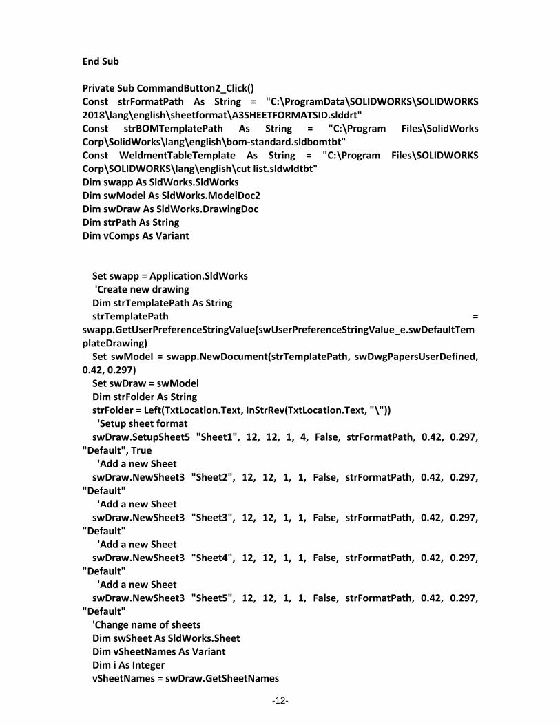
-12-
End Sub Private Sub CommandButton2_Click() Const strFormatPath As String = "C:\ProgramData\SOLIDWORKS\SOLIDWORKS 2018\lang\english\sheetformat\A3SHEETFORMATSID.slddrt" Const strBOMTemplatePath As String = "C:\Program Files\SolidWorks Corp\SolidWorks\lang\english\bom-standard.sldbomtbt" Const WeldmentTableTemplate As String = "C:\Program Files\SOLIDWORKS Corp\SOLIDWORKS\lang\english\cut list.sldwldtbt" Dim swapp As SldWorks.SldWorks Dim swModel As SldWorks.ModelDoc2 Dim swDraw As SldWorks.DrawingDoc Dim strPath As String Dim vComps As Variant Set swapp = Application.SldWorks 'Create new drawing Dim strTemplatePath As String strTemplatePath = swapp.GetUserPreferenceStringValue(swUserPreferenceStringValue_e.swDefaultTemplateDrawing) Set swModel = swapp.NewDocument(strTemplatePath, swDwgPapersUserDefined, 0.42, 0.297) Set swDraw = swModel Dim strFolder As String strFolder = Left(TxtLocation.Text, InStrRev(TxtLocation.Text, "\")) 'Setup sheet format swDraw.SetupSheet5 "Sheet1", 12, 12, 1, 4, False, strFormatPath, 0.42, 0.297, "Default", True 'Add a new Sheet swDraw.NewSheet3 "Sheet2", 12, 12, 1, 1, False, strFormatPath, 0.42, 0.297, "Default" 'Add a new Sheet swDraw.NewSheet3 "Sheet3", 12, 12, 1, 1, False, strFormatPath, 0.42, 0.297, "Default" 'Add a new Sheet swDraw.NewSheet3 "Sheet4", 12, 12, 1, 1, False, strFormatPath, 0.42, 0.297, "Default" 'Add a new Sheet swDraw.NewSheet3 "Sheet5", 12, 12, 1, 1, False, strFormatPath, 0.42, 0.297, "Default" 'Change name of sheets Dim swSheet As SldWorks.Sheet Dim vSheetNames As Variant Dim i As Integer vSheetNames = swDraw.GetSheetNames

-13-
For i = 0 To UBound(vSheetNames) Set swSheet = swDraw.Sheet(vSheetNames(i)) If i = 0 Then swSheet.SetName "007_5f" If i = 1 Then swSheet.SetName "025" If i = 2 Then swSheet.SetName "021" If i = 3 Then swSheet.SetName "023" If i = 4 Then swSheet.SetName "065" Next i 'Activate first sheet vSheetNames = swDraw.GetSheetNames swDraw.ActivateSheet vSheetNames(0) 'Add isometric view of assembly on first sheet Dim swView As SldWorks.view Dim swIsoView As SldWorks.view Set swView = swDraw.CreateDrawViewFromModelView3(strFolder & "GEL007_501.SLDASM", "*Isometric", 0.14, 0.16, 0) Set swIsoView = swView swDraw.ViewDisplayShaded 'Change view scale to 1:25 Dim dblScale(1) As Double dblScale(0) = 1 dblScale(1) = 25 swView.ScaleRatio = dblScale 'Add BOM to first sheet Dim swBOMAnn As SldWorks.BomTableAnnotation Set swBOMAnn = swIsoView.InsertBomTable3(False, 0.4, 0.25, swBOMConfigurationAnchor_TopRight, swBomType_TopLevelOnly, "Default", strBOMTemplatePath, False) 'Change BOM column to reference Part No custom property swBOMAnn.SetColumnCustomProperty 2, "weight" 'Change BOM column name and column widths Dim swTableAnn As SldWorks.TableAnnotation Set swTableAnn = swBOMAnn swTableAnn.Text(0, 2) = "MASS" swTableAnn.SetColumnWidth 1, 0.04, swTableRowColChange_TableSizeCanChange swTableAnn.SetColumnWidth 2, 0.03, swTableRowColChange_TableSizeCanChange 'Rebuild swModel.ForceRebuild3 True 'Create Auto baloon Set swModel = swapp.ActiveDoc Dim vNotes As Variant Dim boolstatus As Boolean

-14-
Dim autoballoonParams As SldWorks.AutoBalloonOptions boolstatus = swModel.ActivateView("Drawing View1") boolstatus = swModel.Extension.SelectByID2("Drawing View1", "DRAWINGVIEW", 0, 0, 0, False, 0, Nothing, 0) boolstatus = swView.SetKeepLinkedToBOM(True, "Bill of Materials1") Set autoballoonParams = swModel.CreateAutoBalloonOptions() autoballoonParams.Layout = swDetailingBalloonLayout_Left autoballoonParams.ReverseDirection = False autoballoonParams.IgnoreMultiple = True autoballoonParams.InsertMagneticLine = False autoballoonParams.LeaderAttachmentToFaces = True autoballoonParams.Style = swBS_Circular autoballoonParams.Size = swBF_3Chars autoballoonParams.UpperTextContent = swBalloonTextItemNumber autoballoonParams.Layername = "-None-" autoballoonParams.ItemNumberStart = 1 autoballoonParams.ItemNumberIncrement = 1 autoballoonParams.ItemOrder = swBalloonItemNumbers_DoNotChangeItemNumbers autoballoonParams.EditBalloons = True autoballoonParams.EditBalloonOption = swEditBalloonOption_Resequence vNotes = swModel.AutoBalloon5(autoballoonParams) 'Rebuild swModel.ForceRebuild3 True 'Activate second sheet swDraw.ActivateSheet vSheetNames(1) Dim str025Path As String str025Path = strFolder & "GEL025_101.sldprt" 'Add isometric view of assembly on second sheet Set swView = swDraw.CreateDrawViewFromModelView3(str025Path, "*Isometric", 0.14, 0.16, 0) Set swIsoView = swView swDraw.ViewDisplayShaded 'Dim swapp As SldWorks.SldWorks Dim oDrawing As DrawingDoc 'Dim swView As View Dim WMTable As SldWorks.WeldmentCutListAnnotation Set swapp = Application.SldWorks Set oDrawing = swapp.ActiveDoc Set swView = oDrawing.GetFirstView Set swView = swView.GetNextView
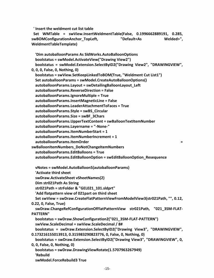
-15-
' Insert the weldment cut list table Set WMTable = swView.InsertWeldmentTable(False, 0.1996662889191, 0.285, swBOMConfigurationAnchor_TopLeft, "Default<As Welded>", WeldmentTableTemplate) 'Dim autoballoonParams As SldWorks.AutoBalloonOptions boolstatus = swModel.ActivateView("Drawing View2") boolstatus = swModel.Extension.SelectByID2("Drawing View2", "DRAWINGVIEW", 0, 0, 0, False, 0, Nothing, 0) boolstatus = swView.SetKeepLinkedToBOM(True, "Weldment Cut List1") Set autoballoonParams = swModel.CreateAutoBalloonOptions() autoballoonParams.Layout = swDetailingBalloonLayout_Left autoballoonParams.ReverseDirection = False autoballoonParams.IgnoreMultiple = True autoballoonParams.InsertMagneticLine = False autoballoonParams.LeaderAttachmentToFaces = True autoballoonParams.Style = swBS_Circular autoballoonParams.Size = swBF_3Chars autoballoonParams.UpperTextContent = swBalloonTextItemNumber autoballoonParams.Layername = "-None-" autoballoonParams.ItemNumberStart = 1 autoballoonParams.ItemNumberIncrement = 1 autoballoonParams.ItemOrder = swBalloonItemNumbers_DoNotChangeItemNumbers autoballoonParams.EditBalloons = True autoballoonParams.EditBalloonOption = swEditBalloonOption_Resequence vNotes = swModel.AutoBalloon5(autoballoonParams) 'Activate third sheet swDraw.ActivateSheet vSheetNames(2) Dim str021Path As String str021Path = strFolder & "GEL021_101.sldprt" 'Add flatpattern view of 021part on third sheet Set swView = swDraw.CreateFlatPatternViewFromModelView3(str021Path, "", 0.12, 0.22, 0, False, True) swDraw.ChangeRefConfigurationOfFlatPatternView str021Path, "021_3SM-FLAT-PATTERN" boolstatus = swDraw.ShowConfiguration2("021_3SM-FLAT-PATTERN") swView.ScaleDecimal = swView.ScaleDecimal / 8# boolstatus = swDraw.Extension.SelectByID2("Drawing View3", "DRAWINGVIEW", 0.173216155013913, 0.315983290823776, 0, False, 0, Nothing, 0) boolstatus = swDraw.Extension.SelectByID2("Drawing View3", "DRAWINGVIEW", 0, 0, 0, False, 0, Nothing, 0) boolstatus = swDraw.DrawingViewRotate(1.5707963267949) 'Rebuild swModel.ForceRebuild3 True

-16-
'Add Dimensions Dim myModelView As Object Set myModelView = swModel.ActiveView myModelView.FrameState = swWindowState_e.swWindowMaximized swModel.ClearSelection2 True boolstatus = swModel.ActivateSheet("021") boolstatus = swModel.ActivateView("Drawing View3") boolstatus = swModel.Extension.SelectByRay(3.99030081147816E-02, 0.253733110158195, -3499.999, 0, 0, -1, 1.90810825190803E-03, 1, False, 0, 0) boolstatus = swModel.Extension.SelectByRay(0.199220372620381, 0.252859743787601, -3499.999, 0, 0, -1, 1.35815376439791E-03, 1, True, 0, 0) Dim myDisplayDim As Object Set myDisplayDim = swModel.AddDimension2(0.121725716651795, 0.28, 0) swModel.ClearSelection2 True boolstatus = swModel.ActivateSheet("021") boolstatus = swModel.ActivateView("Drawing View3") boolstatus = swModel.Extension.SelectByID2("Line23@Bend-Lines2@GEL021_101-1@Drawing View3", "EXTSKETCHSEGMENT", 0.378261538461541, -0.933549236983, 0, False, 0, Nothing, 0) Set myDisplayDim = swModel.AddDimension2(0.213646944885012, 0.213230769230769, 0) swModel.ClearSelection2 True boolstatus = swModel.ActivateSheet("021") swModel.ClearSelection2 True 'Add Additional views Set myModelView = swDraw.ActiveView myModelView.FrameState = swWindowState_e.swWindowMaximized Dim myView As Object Set myView = swDraw.CreateDrawViewFromModelView3(str021Path, "*Isometric", 0.31527425257732, 0.228118846153846, 0) swModel.ClearSelection2 True Set myView = swDraw.CreateDrawViewFromModelView3(str021Path, "*Left", 0.328220406423473, 8.76530769230769E-02, 0) 'Activate fourth sheet swDraw.ActivateSheet vSheetNames(3) Dim str023Path As String str023Path = strFolder & "GEL023_101.sldprt" 'Add flatpattern view of 021part on third sheet Set swView = swDraw.CreateFlatPatternViewFromModelView3(str023Path, "", 0.12, 0.22, 0, False, True) swDraw.ChangeRefConfigurationOfFlatPatternView str023Path, "023_3SM-FLAT-PATTERN" boolstatus = swDraw.ShowConfiguration2("023_3SM-FLAT-PATTERN") swView.ScaleDecimal = swView.ScaleDecimal / 8#

-17-
boolstatus = swDraw.Extension.SelectByID2("Drawing View6", "DRAWINGVIEW", 0.173216155013913, 0.315983290823776, 0, False, 0, Nothing, 0) boolstatus = swDraw.Extension.SelectByID2("Drawing View6", "DRAWINGVIEW", 0, 0, 0, False, 0, Nothing, 0) boolstatus = swDraw.DrawingViewRotate(1.5707963267949) 'Rebuild swModel.ForceRebuild3 True 'Add Dimensions Set myModelView = swModel.ActiveView myModelView.FrameState = swWindowState_e.swWindowMaximized swModel.ClearSelection2 True boolstatus = swModel.ActivateSheet("023") boolstatus = swModel.ActivateView("Drawing View6") boolstatus = swModel.Extension.SelectByID2("Line8@Bend-Lines2@GEL023_101-1@Drawing View6", "EXTSKETCHSEGMENT", 0.140296318918609, 0.407381967351668, 0, False, 0, Nothing, 0) 'Dim myDisplayDim As Object Set myDisplayDim = swModel.AddDimension2(0.117759751902909, 0.281907259303189, 0) swModel.ClearSelection2 True boolstatus = swModel.ActivateSheet("023") boolstatus = swModel.ActivateView("Drawing View6") boolstatus = swModel.Extension.SelectByRay(0.155760661909792, 0.164822116056189, -3499.999, 0, 0, -1, 2.30302358338915E-03, 1, False, 0, 0) boolstatus = swModel.Extension.SelectByRay(0.15372858227739, 0.275909135960842, -3499.999, 0, 0, -1, 2.30302358338915E-03, 1, True, 0, 0) Set myDisplayDim = swModel.AddDimension2(0.205885292842379, 0.215624106890684, 0) swModel.ClearSelection2 True boolstatus = swModel.ActivateSheet("023") swModel.ClearSelection2 True 'Add Additional views Set myModelView = swDraw.ActiveView myModelView.FrameState = swWindowState_e.swWindowMaximized 'Dim myView As Object Set myView = swDraw.CreateDrawViewFromModelView3(str023Path, "*Isometric", 0.31527425257732, 0.228118846153846, 0) swModel.ClearSelection2 True Set myView = swDraw.CreateDrawViewFromModelView3(str023Path, "*Left", 0.328220406423473, 8.76530769230769E-02, 0) 'Activate fifth sheet swDraw.ActivateSheet vSheetNames(4) Dim str065Path As String

-18-
str065Path = strFolder & "GEL065.0101.sldprt" swDraw.Create3rdAngleViews2 str065Path ' Get sheet size Dim cursheet As Sheet Dim sheetwidth As Double, sheetheight As Double Set cursheet = swDraw.GetCurrentSheet cursheet.GetSize sheetwidth, sheetheight Dim view As view Dim vOutline As Variant, vPosition As Variant Dim viewWidth As Double, viewHeight As Double Set view = swDraw.CreateDrawViewFromModelView3(str065Path, "*Isometric", sheetwidth, sheetheight, 0) ' Now get view size and move left and down to bring into sheet vOutline = view.GetOutline vPosition = view.Position viewWidth = vOutline(2) - vOutline(0) viewHeight = vOutline(3) - vOutline(1) vPosition(0) = vPosition(0) - viewWidth vPosition(1) = vPosition(1) - viewHeight view.Position = vPosition ' Insert model dimensions Dim v As view Set v = swDraw.GetFirstView ' Sheet Set v = v.GetNextView ' First view swDraw.ClearSelection2 True While Not v Is Nothing If v.Name <> view.Name Then swDraw.Extension.SelectByID2 v.Name, "DRAWINGVIEW", 0, 0, 0, True, -1, Nothing, 0 Set v = v.GetNextView Wend swDraw.InsertModelAnnotations3 0, 327663, True, True, False, False 'Save drawing swModel.Extension.SaveAs strFolder & "007_5final.SLDDRW", swSaveAsCurrentVersion, 1, _ Nothing, Empty, Empty End Sub
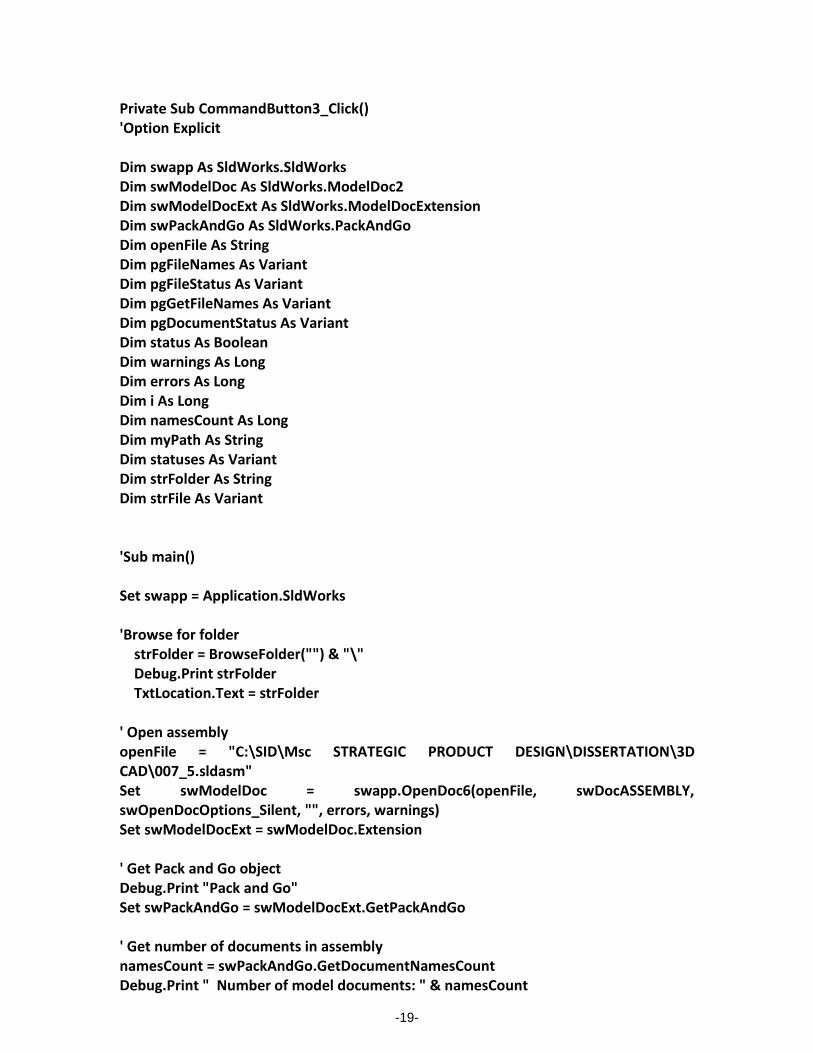
-19-
Private Sub CommandButton3_Click() 'Option Explicit Dim swapp As SldWorks.SldWorks Dim swModelDoc As SldWorks.ModelDoc2 Dim swModelDocExt As SldWorks.ModelDocExtension Dim swPackAndGo As SldWorks.PackAndGo Dim openFile As String Dim pgFileNames As Variant Dim pgFileStatus As Variant Dim pgGetFileNames As Variant Dim pgDocumentStatus As Variant Dim status As Boolean Dim warnings As Long Dim errors As Long Dim i As Long Dim namesCount As Long Dim myPath As String Dim statuses As Variant Dim strFolder As String Dim strFile As Variant 'Sub main() Set swapp = Application.SldWorks 'Browse for folder strFolder = BrowseFolder("") & "\" Debug.Print strFolder TxtLocation.Text = strFolder ' Open assembly openFile = "C:\SID\Msc STRATEGIC PRODUCT DESIGN\DISSERTATION\3D CAD\007_5.sldasm" Set swModelDoc = swapp.OpenDoc6(openFile, swDocASSEMBLY, swOpenDocOptions_Silent, "", errors, warnings) Set swModelDocExt = swModelDoc.Extension ' Get Pack and Go object Debug.Print "Pack and Go" Set swPackAndGo = swModelDocExt.GetPackAndGo ' Get number of documents in assembly namesCount = swPackAndGo.GetDocumentNamesCount Debug.Print " Number of model documents: " & namesCount
-20-
' Include any drawings, SOLIDWORKS Simulation results, and SOLIDWORKS Toolbox components swPackAndGo.IncludeDrawings = False Debug.Print " Include drawings: " & swPackAndGo.IncludeDrawings swPackAndGo.IncludeSimulationResults = False Debug.Print " Include SOLIDWORKS Simulation results: " & swPackAndGo.IncludeSimulationResults swPackAndGo.IncludeToolboxComponents = True Debug.Print " Include SOLIDWORKS Toolbox components: " & swPackAndGo.IncludeToolboxComponents ' Get current paths and filenames of the assembly's documents status = swPackAndGo.GetDocumentNames(pgFileNames) Debug.Print "" Debug.Print " Current path and filenames: " If (Not (IsEmpty(pgFileNames))) Then For i = 0 To UBound(pgFileNames) Debug.Print " The path and filename is: " & pgFileNames(i) Next i End If ' Get current save-to paths and filenames of the assembly's documents status = swPackAndGo.GetDocumentSaveToNames(pgFileNames, pgFileStatus) Debug.Print "" Debug.Print " Current default save-to filenames: " If (Not (IsEmpty(pgFileNames))) Then For i = 0 To UBound(pgFileNames) Debug.Print " The path and filename is: " & pgFileNames(i) Next i End If ' Set folder where to save the files myPath = (strFolder) status = swPackAndGo.SetSaveToName(True, myPath) ' Flatten the Pack and Go folder structure; save all files to the root directory swPackAndGo.FlattenToSingleFolder = True ' Add a prefix and suffix to the new Pack and Go filenames swPackAndGo.AddPrefix = "GEL" swPackAndGo.AddSuffix = "01" ' Verify document paths and filenames after adding prefix and suffix

-21-
ReDim pgGetFileNames(namesCount - 1) ReDim pgDocumentStatus(namesCount - 1) status = swPackAndGo.GetDocumentSaveToNames(pgGetFileNames, pgDocumentStatus) Debug.Print "" Debug.Print " My Pack and Go path and filenames after adding prefix and suffix: " For i = 0 To (namesCount - 1) Debug.Print " My path and filename is: " & pgGetFileNames(i) Next i ' Pack and Go statuses = swModelDocExt.SavePackAndGo(swPackAndGo) swapp.CloseDoc swModelDoc.GetTitle Dim swModel2 As SldWorks.ModelDoc2 Dim swBOMTable As SldWorks.BomTableAnnotation Dim swTable As SldWorks.TableAnnotation Dim swAnn As SldWorks.Annotation Const BOMTemplate As String = "C:\Program Files\SolidWorks Corp\SolidWorks\lang\english\bom-weight.sldbomtbt" Dim OutputPath As String Dim ConfigName As String ' Open assembly OutputPath = TxtLocation.Text & "\GEL007_501.sldasm" openFile = OutputPath Set swModelDoc = swapp.OpenDoc6(openFile, swDocASSEMBLY, swOpenDocOptions_Silent, "", errors, warnings) Set swModelDocExt = swModelDoc.Extension 'Create XLS BOM Set swapp = Application.SldWorks Set swModel2 = swapp.ActiveDoc ConfigName = swModel2.GetActiveConfiguration.Name Set swBOMTable = swModel2.Extension.InsertBomTable(BOMTemplate, 0, 0, swBomType_e.swBomType_PartsOnly, ConfigName) Set swTable = swBOMTable swTable.SaveAsText OutputPath & "BOMTable_" & txtFolderName.Text & ".xls", vbTab Set swAnn = swTable.GetAnnotation swAnn.Select3 False, Nothing swModel2.EditDelete swModel2.ForceRebuild3 True swapp.CloseDoc swModelDoc.GetTitle End Sub