parametric study of foundation of tension and suspension ... · paper presents the parametric study...
TRANSCRIPT

International Research Journal of Engineering and Technology (IRJET) e-ISSN: 2395-0056
Volume: 05 Issue: 04 | Apr-2018 www.irjet.net p-ISSN: 2395-0072
© 2018, IRJET | Impact Factor value: 6.171 | ISO 9001:2008 Certified Journal | Page 1773
Parametric Study of Foundation of Tension and Suspension Tower with
Square and Rectangular Base
Akash M. Popat1, Prof. Paresh G. Patel2
1Post graduate student, 2Associate Professor, 1,2Applied mechanics department,
L.D. College of engineering, Ahmedabad, India
--------------------------------------------------------------***-------------------------------------------------------------Abstract - Foundation of transmission tower plays very important role for safety and better performance of tower as it transmits loads of the transmission system to earth. This paper presents the parametric study of the isolated and pile type of foundation of the self supported suspension and tension type transmission tower for square and rectangular base for different soil conditions. Foundation of tower has been designed for five different base width of tower by changing the ratio of longitudinal face and transverse face LF:TF = 1:1, 1:1.1, 1:1.2, 1:1.3, 1:1.4. Five types of soil conditions were used. From the comparison, it was concluded for every type of soil condition the minimum cost of foundation for suspension tower was for base width ratio LF:TF = 1:1.2 to 1:1.3 and for tension tower minimum cost was for LF:TF = 1:1.3 to 1:1.14. Keyword - Suspension tower, Tension tower, Isolated
Foundation, Pile foundation
1. INTRODUCTION
Because of the present demand of high and extra high voltage transmission the sizes of towers of transmission line are increasing, resulting in very heavy loads and due to that it requires very heavy foundation. In any project of transmission line it requires very large number of foundations. Other than financial aspect, it is also known that the failure of foundation of transmission tower is also a big reason for collapse of tower. These failures are due to certain deficiencies in design or due to construction or classification of foundation. Wastage of resources happened many times because of over safe design of foundation due to inappropriate classification. Due to very different soil conditions occurs in the line of transmission and remoteness of sites, design task and selection for suitable foundation is challenging. The foundations have to be designed for different types of soil to suit the particular type soil conditions.
The study was carried out to check the feasibility of design of isolated and pile foundation for different soil conditions by changing the base width ratio. The main objective of study is to provide the best and economical tower foundation design as per Indian specification for variety of soils.
2. DATA REQUIRED
For the design of any type of transmission tower foundation basic data required are different types of loads coming over foundation and soil data. Following data is required for the design of foundation. 2.1 Types of loads on foundation :
Foundation of transmission towers are generally
subjected to 3 different types of forces: 1. Compressive force (downward thrust) 2. Tensile force or uplift 3. Lateral thrust of side force in both longitudinal
and transverse direction
The magnitude of forces depends on transmission tower type and also on transmission line capacity. The design loads for foundations must be taken 10% higher than these forces from the towers.
2.2 Soil Data :
The following parameters of soil are required for
design of foundation. 1. Density of soil 2. Limit bearing capacity of soil 3. Angle of soil frustum
3. MODEL ANALYSIS AND DESIGN
3.1 Pile foundation
Design of pile foundation has been carried out using
Staad Foundation software. To calculate the capacity of pile the excel sheet has been developed using IS 2911: 2010.
Vertical capacity of pile
- For granular soil
International Research Journal of Engineering and Technology (IRJET) e-ISSN: 2395-0056
Volume: 05 Issue: 04 | Apr-2018 www.irjet.net p-ISSN: 2395-0072
© 2018, IRJET | Impact Factor value: 6.171 | ISO 9001:2008 Certified Journal | Page 1774
- For cohesive soil
Uplift capacity of pile
The uplift capacity of a pile is given by sum of the frictional resistance and the weight of the pile (buoyant or total as relevant). Uplift capacity can be obtained from static formula by ignoring end-bearing but adding weight of the pile (buoyant or total as relevant).
3.2 Excel sheet
Excel sheet has been developed for design and stability
analysis of foundation.
Fig. 1:- Sheet for isolated foundation design
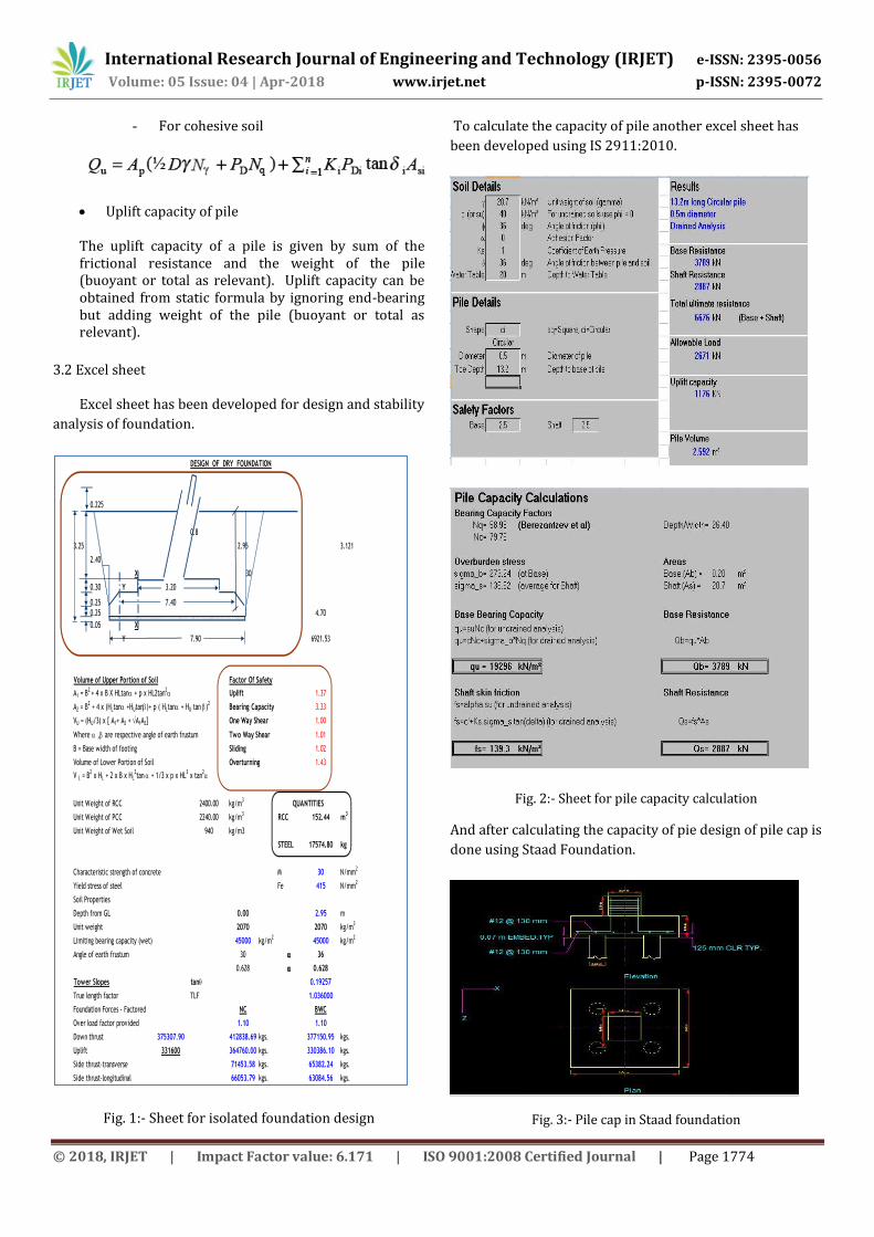
To calculate the capacity of pile another excel sheet has
been developed using IS 2911:2010.
Fig. 2:- Sheet for pile capacity calculation
And after calculating the capacity of pie design of pile cap is
done using Staad Foundation.
Fig. 3:- Pile cap in Staad foundation
0.225
3.25 2.95 3.121
2.40
X 30
0.30 Y 3.20
0.25 7.40
0.25 4.70
0.05 X
Y 6921.53
Volume of Upper Portion of Soil
A1 = B2 + 4 x B X HLtana + p x HL2tan
2a = 1.37
A2 = B2 + 4 x (HLtana +HUtanb)+ p ( HLtana + HU tan b)
2= 3.33
VU = (HU/3) x [ A1+ A2 + A1A2] = 1.00
Where a ,b are respective angle of earth frustum = 1.01
B = Base width of footing = 1.02
Volume of Lower Portion of Soil = 1.43
V L = B2 x HL + 2 x B x HL
2tan a + 1/3 x p x HL
3 x tan
2a
Unit Weight of RCC 2400.00 kg/m3
Unit Weight of PCC 2240.00 kg/m3
RCC 152.44 m3
Unit Weight of Wet Soil 940 kg/m3
STEEL 17574.80 kg
Characteristic strength of concrete M 30 N/mm2
Yield stress of steel Fe 415 N/mm2
Soil Properties
Depth from GL 0.00 2.95 m
Unit weight 2070 2070 kg/m3
Limiting bearing capacity (wet) 45000 kg/m2
45000 kg/m2
Angle of earth frustum 30 a 36
0.628 a 0.628
Tower Slopes tanq 0.19257
True length factor TLF 1.036000
Foundation Forces - Factored NC BWC
Over load factor provided 1.10 1.10
Down thrust 375307.90 412838.69 kgs. 377150.95 kgs.
Uplift 331600 364760.00 kgs. 330386.10 kgs.
Side thrust-transverse 71453.58 kgs. 65382.24 kgs.
Side thrust-longitudinal 66053.79 kgs. 63084.56 kgs.
Overturning
QUANTITIES
Sliding
DESIGN OF DRY FOUNDATION
0.8
7.90
Factor Of Safety
Uplift
Bearing Capacity
One Way Shear
Two Way Shear

International Research Journal of Engineering and Technology (IRJET) e-ISSN: 2395-0056
Volume: 05 Issue: 04 | Apr-2018 www.irjet.net p-ISSN: 2395-0072
© 2018, IRJET | Impact Factor value: 6.171 | ISO 9001:2008 Certified Journal | Page 1775
3.3 Soil data used
For the study of foundation under different soil
conditions five different types of soil has been used for
design of foundation.
TABLE-1. PROPERTIES OF SOIL
S
R
N
O
TYPE
OF SOIL
ANGLE OF
EARTH
FRUSTUM Ф
(DEGREE)
UNIT
WEIGHT
OF SOIL
(KG/CUM)
LIMIT
BEARING
CAPACITY
(KG/SQM)
1 DENSE
SAND
36 2070 45000
2 LOOSE
SAND
29 1750 25000
3 SILTY
SAND
27 1750 15000
4 STIFF
CLAY
17 2000 20000
5 SOFT
CLAY
17 1750 10000
4. RESULTS AND DISCUSSIONS
For the comparative study of design and cost of foundation five different type of soil has been used as shown above. 400kv suspension and tension tower foundations has been designed for five different base ratio of longitudinal face to transverse face LF:TF for 1:1.0 to 1:1.4 for all the five types of soil conditions. So total of 100 numbers of foundations has been designed. From that schedule of model for suspension tower has been shown below.
TABLE-2 MODEL SCHEDULE
RATIO DENSE SAND
LOOSE SAND
SILTY SAND
STIFF CLAY
SOFT CLAY
1:1 S110DS S110LS S110SS S110STC S110SOC
1:1.1 S111DS S111LS S111SS S111STC S111SOC
1:1.2 S112DS S112LS S112SS S112STC S112SOC
1:1.3 S113DS S113LS S113SS S113STC S113SOC
1:1.4 S114DS S114LS S114SS S114STC S114SOC
- Model name description:
S110DS – Suspension tower for base width ratio of longitudinal face to transverse face LF : TF = 1:1.0 for dense sand type soil condition.
- Comparison of cost of suspension and tension tower foundation is done for isolated and pile foundation for same type of soil condition by varying the base width ratio
Fig. 4:- Cost comparisons for dense sand
Fig. 5:- Cost comparisons for loose sand
Fig. 6:- Cost comparisons for silty sand
0
200000
400000
600000
800000
1000000
1200000
1400000
1600000
1800000
2000000
AP
PR
OX
. CO
ST
MODEL
DENSE SAND
SUSPENSION
TENSION
0
500000
1000000
1500000
2000000
2500000
AP
PR
OX
. CO
ST
MODEL
LOOSE SAND
SUSPENSION
TENSION
0
500000
1000000
1500000
2000000
2500000
AP
PR
OX
. CO
ST
MODEL
SILTY SAND
SUSPENSION
TENSION

International Research Journal of Engineering and Technology (IRJET) e-ISSN: 2395-0056
Volume: 05 Issue: 04 | Apr-2018 www.irjet.net p-ISSN: 2395-0072
© 2018, IRJET | Impact Factor value: 6.171 | ISO 9001:2008 Certified Journal | Page 1776
Fig. 7:- Cost comparisons for stiff clay
Fig. 8:- Cost comparisons for soft clay
5. CONCLUSIONS
- This study shows us foundation design as per different loadings and as per varying soil conditions for different base width ratio of transmission tower.
- Size of foundation and cost is less for suspension type tower than tension tower.
- For isolated foundation, for every type of soil minimum cost can be achieved by taking the base width ratio between longitudinal face to transverse face as 1:1.2 to 1:1.3
- For pile foundation, for every type of soil minimum cost can be achieved by taking the base width ratio between longitudinal face to transverse face as 1:1.3 to 1:1.4
- Percentage reduction in cost is 8-9% for isolated foundation whereas for pile foundation percentage reduction is 13%.
REFERENCES
[1] Indian Standard 802 (Part 1 / Sec 1) : 2015 - Use of Structural Steel in Overhead Transmission Line Towers — Code of Practice
[2] Indian Standard 4091-1979 - Code of practice for
design and construction of foundations for transmission line towers and poles.
[3] CBIP (Central Board of Irrigation and Power)
Transmission Line Manual – 323
[4] Santhakumar A.R. and Murthy, “Transmission line
structure”
[5] Viral R Kapadiya, “Comparative Study of 400 kv
M/C Tension and Suspension Tower with Square
and Rectangular Base” (2017), L.D. College of
Engineering.
[6] Dongxue Hao, Rong Chen, Guangsen Fan, “Ultimate
Uplift Capacity of Transmission Tower Foundation in Undisturbed Excavated Soil”, ELSEVIER 2012.
[7] IS 2911-2010 - Design and construction of pile
foundation – Code of Practice
0500000
100000015000002000000250000030000003500000
AP
PR
OX
. CO
ST
MODEL
STIFF CLAY
SUSPENSION
TENSION
0500000
1000000150000020000002500000300000035000004000000
AP
PR
OX
. CO
ST
MODEL
SOFT CLAY
SUSPENSION
TENSION