park assist / monitoring – clearance sonar system …fjcruiser-club.com/docs/rm/park...
TRANSCRIPT
PARK ASSIST / MONITORING – CLEARANCE SONAR SYSTEM PM–1
M
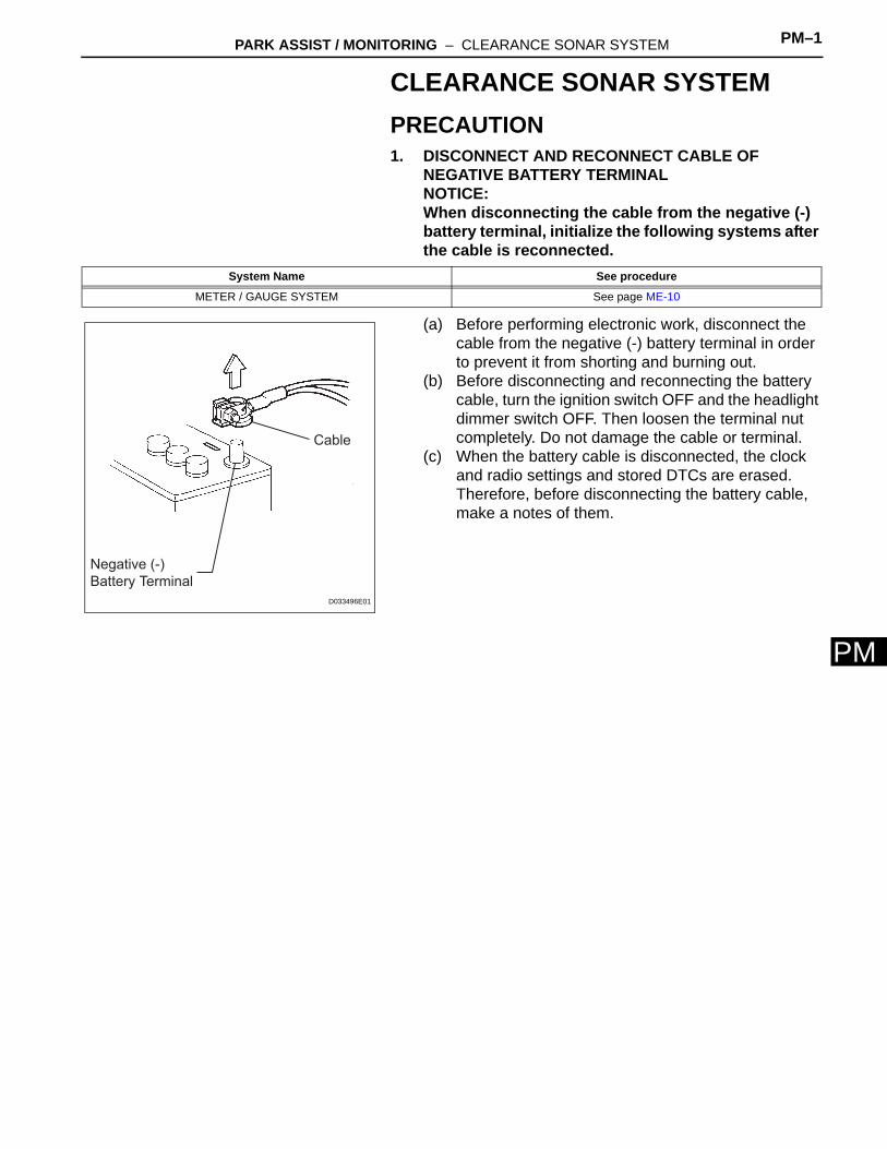
PCLEARANCE SONAR SYSTEMPRECAUTION1. DISCONNECT AND RECONNECT CABLE OF
NEGATIVE BATTERY TERMINALNOTICE:When disconnecting the cable from the negative (-) battery terminal, initialize the following systems after the cable is reconnected.
(a) Before performing electronic work, disconnect the cable from the negative (-) battery terminal in order to prevent it from shorting and burning out.
(b) Before disconnecting and reconnecting the battery cable, turn the ignition switch OFF and the headlight dimmer switch OFF. Then loosen the terminal nut completely. Do not damage the cable or terminal.
(c) When the battery cable is disconnected, the clock and radio settings and stored DTCs are erased. Therefore, before disconnecting the battery cable, make a notes of them.
System Name See procedure
METER / GAUGE SYSTEM See page ME-10
Negative (-)
Battery Terminal
Cable
D033496E01

PM–2 PARK ASSIST / MONITORING – CLEARANCE SONAR SYSTEM
PM
PARTS LOCATION
NO. 1 ULTRASONIC SENSOR (LH)
NO. 1 ULTRASONIC SENSOR (RH)
CLEARANCE WARNING ECU
CLEARANCE WARNING BUZZER
BACK SONAR SWITCH
ASSEMBLYMAIN BODY ECU
(DRIVER SIDE J/B)
- IG1 FUSE
IGNITION SWITCH
I102667E01

PARK ASSIST / MONITORING – CLEARANCE SONAR SYSTEM PM–3
M
PPARK / NEUTRAL POSITION SWITCH
FOR A/T:
BACK-UP LIGHT SWITCH
FOR M/T:
B140771E01

PM–4 PARK ASSIST / MONITORING – CLEARANCE SONAR SYSTEM
PM
SYSTEM DIAGRAM
Clearance
Warning
ECU
Clearance Warning Buzzer
No. 1 Ultrasonic Sensor (LH)
No. 1 Ultrasonic Sensor (RH)
Back Sonar Switch
Park/Neutral Position Switch*2
Back-up Light Switch*1
*2: For Automatic Transmission
*1: For Manual Transmission
I102679E01

PARK ASSIST / MONITORING – CLEARANCE SONAR SYSTEM PM–5
M
PSYSTEM DESCRIPTION1. GENERAL
(a) This system uses ultrasonic sensors to detect obstacles at the rear of the vehicle. The system then informs the driver of the approximately distance between the sensors and the obstacles by sounding a buzzer.
2. FUNCTIONS OF COMPONENTS
3. OPERATION EXPLANATION(a) The clearance warning ECU determines whether
the clearance sonar system should operate or not based on the back sonar switch on/off status and the shift lever position.
(b) When the system operates, the clearance warning ECU transmits ultrasonic waves from the ultrasonic sensor. If an obstacle is detected within a sensor's detection range, the waves are reflected back to the sensors. The sensor then transmits a signal to the clearance warning ECU. Based on this information, the clearance warning ECU sends signals to the clearance warning buzzer. The approximate distance between the vehicle and the obstacle is then communicated through different types of buzzer sounds.HINT:Refer to "OPERATION CHECK" for detailed operation (See page PM-7).
4. NOTE FOR CLEARANCE SONAR SYSTEM(a) Under the following conditions, the ultrasonic sensor
may not operate properly.(1) Foreign matter such as snow or mud is on
sensor (the detection function returns to normal if foreign matter is cleared away).
(2) The sensor is frozen (the detection function returns to normal if defrosted).HINT:Especially in cold weather, the sensor may not be able to detect obstacles if it is frozen or otherwise affected by the weather.
(b) The detection range of the ultrasonic sensor may be affected by the following condition:(1) Foreign matter such as snow or mud is on the
sensor.
Components Function
Ultrasonic Sensor Detects distance between vehicle and obstacle
Back Sonar Switch Turns the clearance sonar system on and off
Clearance Warning Buzzer Emits an intermittent sound to inform the driver that the ECU has detected an obstacle within prescribed ranges
Clearance Warning ECU • Judges approximate distance between vehicle and obstacle• ECU has buzzer sound volume adjusting knob
Park / Neutral Position Switch (A/T) Sends a signal that activates the clearance sonar system when the shift lever is moved to the R position
Back-up Light Switch (M/T) Transmits reverse shift position signal to clearance warning ECU
PM–6 PARK ASSIST / MONITORING – CLEARANCE SONAR SYSTEM
PM
(2) In very hot or cold weather.(c) Under the following conditions, the clearance sonar
system may detect an error.(1) Another vehicle's horn, motorcycle engine
sounds, an approaching vehicle's air brake sound, or other things that generate ultrasonic waves are near the vehicle.
(2) The vehicle gets caught in a downpour, or mud or water splashes onto the vehicle's body.
(3) The vehicle is severely tilted.(4) The vehicle is equipped with a commercial
fender pole.(5) Foreign matter such as snow or mud is on the
sensor.(6) A vehicle equipped with a sonar system is in the
vicinity.(7) The vehicle is equipped with a towing hook.
(d) The clearance sonar system cannot detect the following objects:(1) Thin objects like wires, ropes or poles.(2) Materials that easily absorb the ultrasonic waves
such as cotton, snow, etc.(3) Objects with sharp edges.(4) Short objects.(5) Tall objects with a protruding or overhanging
upper part.(e) Other conditions
(1) The sensor cannot detect an object under the bumper. Also, the sensor may detect an object and then lose track of the object if: 1) the object starts out in the detection range and then ends up below the sensor, or 2) the object is a thin pole, such as a picket.
(2) The sensor may be unable to detect objects when the sensor is too close to the objects.
(3) The sensor may not operate properly if it is dropped or subjected to a strong impact.

PARK ASSIST / MONITORING – CLEARANCE SONAR SYSTEM PM–7
M
PHOW TO PROCEED WITH TROUBLESHOOTING
NEXT
Standard voltage:11 to 14 V
If the voltage is below 11 V, recharge or replace the battery before proceeding.
NEXT
Result
B
A
(a) Operation check (See page PM-7).(b) Terminals of ECU (See page PM-11).
NEXT
NEXT
NEXT
1 VEHICLE BROUGHT TO WORKSHOP
2 INSPECT BATTERY VOLTAGE
3 PROBLEM SYMPTOMS TABLE
Result Proceed to
Fault is not listed in problem symptoms table A
Fault is listed in problem symptoms table B
Go to step 5
4 OVERALL ANALYSIS AND TROUBLESHOOTING
5 ADJUST, REPAIR OR REPLACE
6 CONFIRMATION TEST
END

PM–8 PARK ASSIST / MONITORING – CLEARANCE SONAR SYSTEM
PM
OPERATION CHECK1. DETECTION RANGE MEASUREMENT AND
INDICATOR CHECK(a) Turn the ignition switch ON.(b) Move the shift lever to the reverse position (when
the back sonar is checked).NOTICE:Apply the parking brake securely so that the vehicle does not move.
(c) Turn the back sonar switch ON.(d) Move a φ 60 mm (2.36 in.) pole around the sensor to
measure the detection ranges of the sensor.NOTICE:The measured detection ranges are for a φ 60 mm (2.36in.) pole. The detection ranges for walls and other obstacles are different.
(e) Check the buzzer sounding condition when the ultrasonic sensor detects an obstacle.
Operation condition
HINT:Since sound waves are used for the detection range measurement, the detection range may vary a little due to the outside air temperature.
Ultrasonic Sensor Detection Range:
Approximately 200 mm (7.87 in.)
Approximately 1,100 mm (43.31 in.)
Approximately 400 mm (15.75 in.)
Approximately 500 mm (19.69 in.)
Approximately 1,600 mm (62,99 in.)
I102680E01
Ignition switch Clearance sonar main switch Shift position
ON ON Reverse Position
PARK ASSIST / MONITORING – CLEARANCE SONAR SYSTEM PM–9
M
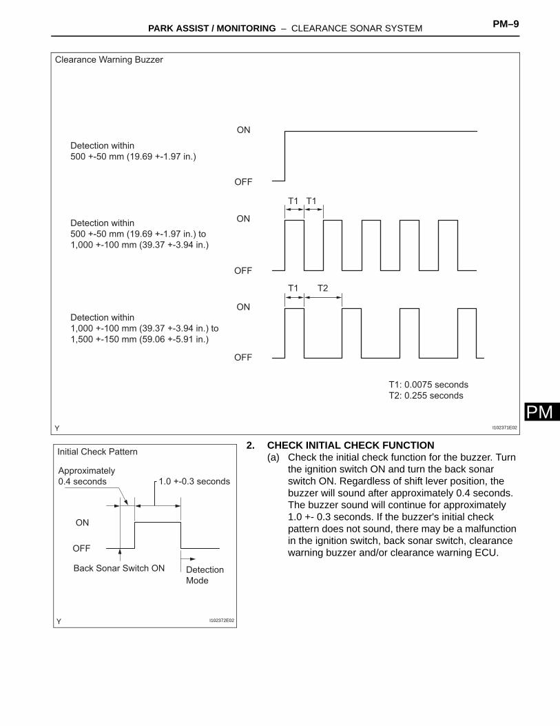
P2. CHECK INITIAL CHECK FUNCTION(a) Check the initial check function for the buzzer. Turn the ignition switch ON and turn the back sonar switch ON. Regardless of shift lever position, the buzzer will sound after approximately 0.4 seconds. The buzzer sound will continue for approximately 1.0 +- 0.3 seconds. If the buzzer's initial check pattern does not sound, there may be a malfunction in the ignition switch, back sonar switch, clearance warning buzzer and/or clearance warning ECU.
Detection within
500 +-50 mm (19.69 +-1.97 in.)
Detection within
500 +-50 mm (19.69 +-1.97 in.) to
1,000 +-100 mm (39.37 +-3.94 in.)
Detection within
1,000 +-100 mm (39.37 +-3.94 in.) to
1,500 +-150 mm (59.06 +-5.91 in.)
OFF
ON
OFF
ON
OFF
ON
T1
T1T1
T2
T1: 0.0075 seconds
T2: 0.255 seconds
Clearance Warning Buzzer
I102371E02
Detection
Mode
Back Sonar Switch ON
ON
OFF
Approximately
0.4 seconds 1.0 +-0.3 seconds
Initial Check Pattern
I102372E02

PM–10 PARK ASSIST / MONITORING – CLEARANCE SONAR SYSTEM
PM
(b) After checking the initial check function, check that the buzzer fault pattern does not sound. If the buzzer fault pattern sounds, there may be a problem with the sensor and/or sensor wire harness. The fault pattern will continue sounding until the problem is fixed.
3. ADJUST BUZZER VOLUME(a) Turn the knob on the clearance warning ECU to
adjust the volume.
Fault Pattern
ON
OFF
Buzzer
+-0.025 seconds
1.5 +-0.5 seconds (1 cycle)
0.75 +-0.075 seconds
Normal Return
I102373E02
VOLUMU
ABS
I102663

PARK ASSIST / MONITORING – CLEARANCE SONAR SYSTEM PM–11
M
PPROBLEM SYMPTOMS TABLEHINT:• Use the table below to help determine the cause of the
problem symptom. The potential causes of the symptoms are listed in order of probability in the "Suspected area" column of the table. Check each symptom by checking the suspected areas in the order they are listed. Replace parts as necessary.
• Inspect the fuses and relays related to this system before inspecting the suspected areas below.
Clearance sonar systemSymptom Suspected area See page
Initial check does not function
1. Clearance sonar main switch circuit PM-19
2. Clearance sonar buzzer circuit PM-21
3. Clearance warning buzzer PM-21
4. Wire harness -
5. Clearance warning ECU PM-11
Clearance sonar system does not function (Initial check functions normally)
1. Initial check -
2. Back sonar sensor LH circuit PM-15
3. Back sonar sensor RH circuit PM-17
4. Back-up light switch circuit PM-12
5. Wire harness -
6. Clearance warning ECU PM-11
Buzzer volume is too low 1. Adjust buzzer volume PM-7

PM–12 PARK ASSIST / MONITORING – CLEARANCE SONAR SYSTEM
PM
TERMINALS OF ECU1. CLEARANCE WARNING ECU
(a) Disconnect the E31 ECU connector.(b) Measure the voltage of the wire harness side
connector.Standard voltage:
If the result is not as specified, there may be a malfunction on the wire harness side.
(c) Reconnect the ECU connector.(d) Measure the voltage of the connector.
Standard voltage:
If the result is not as specified, the ECU may have a malfunction.
123456789101112
E31
I102375E02
Symbols (Terminal No.) Wiring Color Terminal Description Condition Specified Condition
+B (E31-3) - Body ground LG - Body ground +B power supply
Ignition switch ON, back sonar switch ON 11 to 14 V
Ignition switch ON, back sonar switch OFF Below 1 V
E (E31-10) - Body ground W-B - Body ground Body ground Always Below 1 V
Symbols (Terminal No.) Wiring Color Terminal Description Condition Specified Condition
BBZ (E31-2) - E (E 31-10) L-B - W-B Buzzer input
Ignition switch ON, back sonar switch ON Pulse generation
Ignition switch ON, back sonar switch OFF Below 1 V
S6 (E31-12) - E1 (E31-11) P - Y No. 1 ultrasonic sensor (LH)
When signal transmitted from ECU to No. 1 ultrasonic
sensor (LH)Pulse generation
S5 (E31-6) - E2 (E31-5) B - W No. 1 ultrasonic sensor (RH)
When signal transmitted from ECU to No. 1 ultrasonic
sensor (RH)
RL (E31-8) - Body ground R-Y - Body ground Back-up light switch signal input
Ignition switch ON, shift lever in reverse position 11 to 14 V
Ignition switch ON, shift lever except reverse position Below 1 V

PARK ASSIST / MONITORING – CLEARANCE SONAR SYSTEM PM–13
M
PDESCRIPTIONThis circuit sends a signal of the back-up light switch or park/neutral position switch to the clearance warning ECU.
WIRING DIAGRAM
Back-up Light Circuit
Clearance Warning ECU
RL
Back-up Light Switch*1
IG1
AM1
AM1
IG1
Ignition Switch
ALTPark/Neutral Position Switch*2
RB RL
R
*2: For Automatic Tranmission
*1: For Manual Transmission
Battery
*1 *1
*2 *2
I102664E01

PM–14 PARK ASSIST / MONITORING – CLEARANCE SONAR SYSTEM
PM
INSPECTION PROCEDURE
(a) For manual transmission.(1) Remove the back-up light switch.(2) Measure the resistance of the switch.
Standard resistance
(3) Reinstall the back-up light switch.
(b) For automatic transmission.(1) Disconnect the B35 park / neutral position switch
connector.(2) Measure the resistance.
Standard resistance
(3) Reconnect the park / neutral position switch connector.
NG
OK
1 INSPECT BACK-UP LIGHT SWITCH OR PARK/NEUTRAL POSITION SWITCH
12
Component Side:
Back-up Light Switch
I102381E01
Tester Connection Switch Condition Specified Condition
1 - 2Pushed Below 1 Ω
Not pushed 10 kΩ or higher
Component Side:
RB RL
Park / Neutral Position Switch
C110340E31
Tester Connection Shift Position Specified Condition
B35-2 (RB) - B35-1 (RL) R Below 1 Ω
B35-2 (RB) - B35-1 (RL) Except R 10 kΩ or higher
REPLACE BACK-UP LIGHT SWITCH OR PARK/NEUTRAL POSITION SWITCH

PARK ASSIST / MONITORING – CLEARANCE SONAR SYSTEM PM–15
M
P(a) Disconnect the B35 or B42 switch connector.(b) Disconnect the E31clearance warning ECU connector.(c) Measure the voltage of the wire harness side connector.
Standard voltageFor manual transmission:
For automatic transmission:
(d) Measure the resistance of the wire harness side connectors.Standard resistanceFor manual transmission:
For automatic transmission:
(e) Reconnect the switch connector.(f) Reconnect the ECU connector.
NG
OK
2 CHECK HARNESS AND CONNECTOR (SWITCH - CLEARANCE WARNING ECU AND BATTERY)
1 2
1 2 3 4 5 6
7 8 9 10 11 12
1 2 3
5 6 7 8 9
4
Wire Harness Side:
B35
RB
Back-up Light Switch Connector
Clearance Warning ECU Connector
Park / Neutral Position Switch Connector
Front View
Front View
Front View
B42
E31RL
(For M/T)
(For A/T)
RL
I102665E01
Tester Connection Switch Condition Specified Condition
B42-2 - Body ground Ignition switch ON 11 to 14 V
Tester Connection Switch Condition Specified Condition
B35-2 (RB) - Body ground Ignition switch ON 11 to 14 V
Tester Connection Specified Condition
B42-1 - E31-8 (RL) Below 1 Ω
Tester Connection Specified Condition
B35-1 (RL) - E31-8 (RL) Below 1 Ω
REPAIR OR REPLACE HARNESS OR CONNECTOR
PROCEED TO NEXT CIRCUIT INSPECTION SHOWN IN PROBLEM SYMPTOMS TABLE

PM–16 PARK ASSIST / MONITORING – CLEARANCE SONAR SYSTEM
PM
DESCRIPTIONAn ultrasonic sensor consists of a sensor portion that transmits and receives ultrasonic waves and a pre-amplifier that amplifies them. The ultrasonic sensor outputs the ultrasonic waves and sends the received signals to the clearance warning ECU.
WIRING DIAGRAM
INSPECTION PROCEDURE
(a) Remove the No. 1 ultrasonic sensor.(b) Measure the resistance.
Standard resistance
(c) Reinstall the sensor.
NG
OK
Back Sonar Sensor LH Circuit
1 INSPECT NO.1 ULTRASONIC SENSOR
Clearance Warning ECU
No. 1 Ultrasonic Sensor (LH)
S E
S6
E1
B132694E01
2 1
I102666E01
Tester connection Specified condition
1 - 2 8 to 12 kΩ
REPLACE NO. 1 ULTRASONIC SENSOR

PARK ASSIST / MONITORING – CLEARANCE SONAR SYSTEM PM–17
M
P(a) Disconnect the E31 clearance warning ECU connector.(b) Disconnect the N1 connector from the No. 1 ultrasonic
sensor.(c) Measure the resistance .
Standard resistance
(d) Reconnect the ECU connector.(e) Reconnect the sensor connector.
NG
OK
2 CHECK HARNESS AND CONNECTOR (CLEARANCE WARNING ECU - NO. 1 ULTRASONIC SENSOR)
1 2
Wire Harness Side:
Clearance Warning ECU
No. 1 Ultrasonic Sensor (LH)
E31
N1
SE
S6E1
B132712E03
Tester connection Specified condition
S6 (E31-12) - S (N1-2) Below 1 Ω
E1 (E31-11) - E (N1-1) Below 1 Ω
S6 (E31-12) - Body ground 10 kΩ or higher
E1 (E31-11) - Body ground 10 kΩ or higher
REPAIR OR REPLACE HARNESS OR CONNECTOR
PROCEED TO NEXT CIRCUIT INSPECTION SHOWN IN PROBLEM SYMPTOMS TABLE

PM–18 PARK ASSIST / MONITORING – CLEARANCE SONAR SYSTEM
PM
DESCRIPTIONAn ultrasonic sensor consists of a sensor portion that transmits and receives ultrasonic waves and a pre-amplifier that amplifies them. The ultrasonic sensor outputs the ultrasonic waves and sends the received signals to the clearance warning ECU.
WIRING DIAGRAM
INSPECTION PROCEDURE
(a) Remove the No. 1 ultrasonic sensor.(b) Measure the resistance.
Standard resistance
(c) Reinstall the sensor.
NG
OK
Back Sonar Sensor RH Circuit
1 INSPECT NO. 1 ULTRASONIC SENSOR
Clearance Warning ECU
No. 1 Ultrasonic Sensor (RH)
S E
S5
E2
B132694E02
2 1
I102666E01
Tester connection Specified condition
1 - 2 8 to 12 kΩ
REPLACE NO. 1 ULTRASONIC SENSOR

PARK ASSIST / MONITORING – CLEARANCE SONAR SYSTEM PM–19
M
P(a) Disconnect the E31 clearance warning ECU connector.(b) Disconnect the M1 No. 1 ultrasonic sensor connector.(c) Measure the resistance.
Standard resistance
(d) Reconnect the ECU connector.(e) Reconnect the sensor connector.
NG
OK
2 CHECK HARNESS AND CONNECTOR (CLEARANCE WARNING ECU - NO. 1 ULTRASONIC SENSOR)
1 2
Wire Harness Side:
Clearance Warning ECU
No. 1 Ultrasonic Sensor (RH)
E31
M1
SE
S5E2
B132712E04
Tester connection Specified condition
S5 (E31-6) - S (M1-2) Below 1 Ω
E2 (E31-5) - E (M1-1) Below 1 Ω
S5 (E31-6) - Body ground 10 kΩ or higher
E2 (E31-5) - Body ground 10 kΩ or higher
REPAIR OR REPLACE HARNESS OR CONNECTOR
PROCEED TO NEXT CIRCUIT INSPECTION SHOWN IN PROBLEM SYMPTOMS TABLE

PM–20 PARK ASSIST / MONITORING – CLEARANCE SONAR SYSTEM
PM
DESCRIPTIONTurning this switch on activates the clearance sonar system.
WIRING DIAGRAM
INSPECTION PROCEDURE
(a) Remove the back sonar switch.(b) Check the resistance.
Standard resistance
(c) Reinstall the back sonar switch.
NG
OK
Clearance Sonar Main Switch Circuit
1 INSPECT BACK SONAR SWITCH ASSEMBLY
Clearance Warning ECU
Assembly
+B
E
ECU
E
IGAM1
AM1
IG1
IG1
Back Sonar Switch
Assembly
Ignition Switch
ALT
Battery
B132696E02
66 5 4 3 2 1
ECUE IG
Back Sonar Switch:
I102377E02
Tester Connection Switch Condition Specified Condition
3 (IG) - 4 (ECU)Back sonar switch ON Below 1 Ω
Back sonar switch OFF 1 MΩ or higher
3 (IG) - 6 (E)Back sonar switch ON Below 30 Ω
Back sonar switch OFF 10 kΩ or higher
REPLACE BACK SONAR SWITCH ASSEMBLY

PARK ASSIST / MONITORING – CLEARANCE SONAR SYSTEM PM–21
M
P(a) Disconnect the E12 back sonar switch connector.(b) Disconnect the E31 clearance warning ECU connector.(c) Measure the voltage of the wire harness side connector.
Standard voltage
(d) Check the resistance.Standard resistance
(e) Reconnect the switch connector.(f) Reconnect the ECU connector.
NG
OK
(a) Disconnect the E31 clearance warning ECU connector.(b) Measure the voltage of the wire harness side connector.
Standard voltage
(c) Reconnect the ECU connector.
OK
NG
2 CHECK HARNESS AND CONNECTOR (SWITCH - ECU, BATTERY AND BODY GROUND)
1 2 3 4 5 6
7 8 9 10 11 12
1 2 3 4 5 6
Clearance Warning ECU
E31
Wire Harness Side:
Back Sonar Switch
E12
ECUIG
+B
E
Front View
Front View
E
I102378E02
Tester Connection Switch Condition Specified Condition
E12-3 (IG) - Body ground Ignition switch ON 11 to 14 V
Tester Connection Specified Condition
E12-4 (ECU) - E31-3 (+B)
Below 1 ΩE12-6 (E) - Body ground
E31-10 (E) - Body ground
REPAIR OR REPLACE HARNESS OR CONNECTOR
3 CHECK CLEARANCE WARNING ECU ASSEMBLY
Wire Harness Side:
E31
E
+B
Front ViewF100692E09
Tester Connection Switch Condition Specified Condition
E31-3 (+B) - E31-10 (E) Ignition switch ON, back sonar switch ON 11 to 14 V
REPLACE CLEARANCE WARNING ECU ASSEMBLY
PROCEED TO NEXT CIRCUIT INSPECTION SHOWN IN PROBLEM SYMPTOMS TABLE

PM–22 PARK ASSIST / MONITORING – CLEARANCE SONAR SYSTEM
PM
DESCRIPTIONThe clearance warning ECU receives the ultrasonic sensor signal to sound the clearance warning buzzer.
WIRING DIAGRAM
INSPECTION PROCEDURE
(a) Disconnect the E10 clearance warning buzzer connector.
(b) Disconnect the E31 clearance warning ECU connector.(c) Measure the voltage of the wire harness side connector.
Standard voltage
(d) Check the resistance.Standard resistance
(e) Reconnect the buzzer connector.(f) Reconnect the ECU connector.
NG
Clearance Warning Buzzer Circuit
1 CHECK HARNESS AND CONNECTOR (BUZZER - ECU AND BATTERY)
Clearance Warning ECU
BBZ
Clearance Warning Buzzer
IG1From
Ignition Switch
B132695E02
1 2 3 4 5 6
7 8 9 10 11 12
1 2
Wire Harness Side:
Clearance Warning ECU
Clearance Warning Buzzer
E31
E10
BBZ
I102380E02
Tester Connection Switch Condition Specified Condition
E10-1 - Body ground Ignition switch ON 11 to 14 V
Tester Connection Specified Condition
E10-2 - E31-2 (BBZ) Below 1 Ω
REPAIR OR REPLACE HARNESS OR CONNECTOR

PARK ASSIST / MONITORING – CLEARANCE SONAR SYSTEM PM–23
M
POK
PROCEED TO NEXT CIRCUIT INSPECTION SHOWN IN PROBLEM SYMPTOMS TABLE

PARK ASSIST / MONITORING – CLEARANCE WARNING ECU PM–23
M
PBODY ELECTRICALPARK ASSIST / MONITORINGCLEARANCE WARNING ECUCOMPONENTS
ASSIST GRIP
ASSEMBLY
ASSIST GRIP
PLUG
ASSIST GRIP
RETAINER LH
ASSIST GRIP
RETAINER RH
COWL SIDE
TRIM BOARD LH
COWL SIDE
TRIM BOARD RH
FOOTREST CLIP
FRONT DOOR OPENING
TRIM WEATHERSTRIP LH
FRONT DOOR OPENING
TRIM WEATHERSTRIP RH
FRONT DOOR SCUFF PLATE LH
FRONT DOOR SCUFF PLATE RH
FRONT FLOOR
FOOTREST
FRONT PILLAR
GARNISH LH
FRONT PILLAR
GARNISH RH
N*m (kgf*cm, ft*lbf) : Specified torque
29 (296, 21)
x2
x2
29 (296, 21)
FOOTREST CLIP
ASSIST GRIP
PLUG
ASSIST GRIP
ASSEMBLY
B138483E01

PM–24 PARK ASSIST / MONITORING – CLEARANCE WARNING ECU
PM
FRONT CONSOLE BOX
FRONT CONSOLE BOX
BOTTOM MAT
FRONT CONSOLE BOX UPPER
PANEL SUB-ASSEMBLY
PARKING BRAKE HOLE
COVER SUB-ASSEMBLY
SHIFT LEVER KNOB
SUB-ASSEMBLYSHIFT LEVER KNOB
SUB-ASSEMBLY
x4
SHIFT LEVER KNOB
SUB-ASSEMBLY
for Manual Transmission:for Automatic Transmission 4WD:
B138638E01
PARK ASSIST / MONITORING – CLEARANCE WARNING ECU PM–25
M
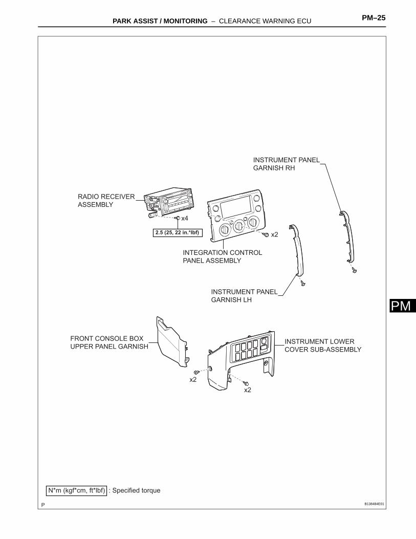
PFRONT CONSOLE BOX
UPPER PANEL GARNISHINSTRUMENT LOWER
COVER SUB-ASSEMBLY
INSTRUMENT PANEL
GARNISH LH
INSTRUMENT PANEL
GARNISH RH
INTEGRATION CONTROL
PANEL ASSEMBLY
RADIO RECEIVER
ASSEMBLY
N*m (kgf*cm, ft*lbf) : Specified torque
2.5 (25, 22 in.*lbf)
x2
x2
x2
x4
B138484E01

PM–26 PARK ASSIST / MONITORING – CLEARANCE WARNING ECU
PM
COMBINATION METER
ASSEMBLY
GLOVE COMPARTMENT
DOOR ASSEMBLY
HOOD LOCK CONTROL
LEVER SUB-ASSEMBLY
INSTRUMENT CLUSTER
LOWER FINISH PANEL
INSTRUMENT LOWER
PANEL
INSTRUMENT PANEL
LOWER FINISH PANEL
SUB-ASSEMBLY LH
INSTRUMENT PANEL LOWER
FINISH PANEL SUB-ASSEMBLY RH
INSTRUMENT PANEL
REGISTER ASSEMBLY LH
INSTRUMENT PANEL
REGISTER ASSEMBLY RH
N*m (kgf*cm, ft*lbf) : Specified torque
7.0 (71, 62 in.*lbf)
x4
x4
x2
B138485E01
PARK ASSIST / MONITORING – CLEARANCE WARNING ECU PM–27
M
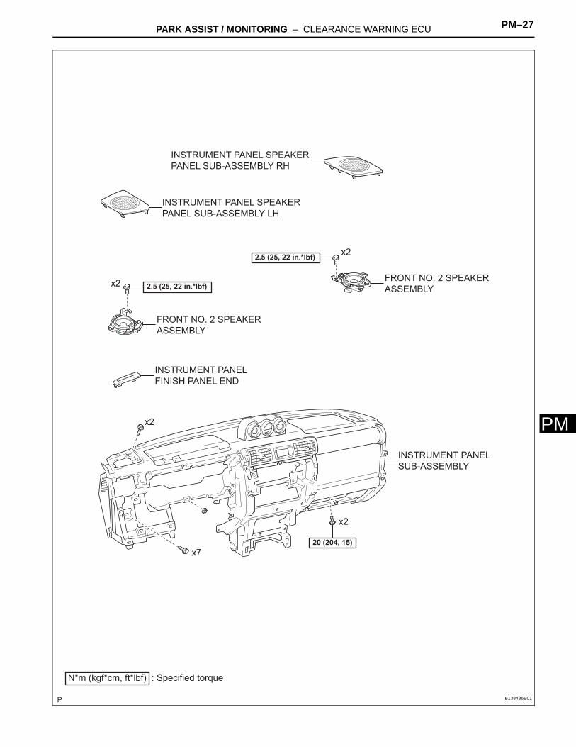
PFRONT NO. 2 SPEAKER
ASSEMBLY
INSTRUMENT PANEL SPEAKER
PANEL SUB-ASSEMBLY LH
INSTRUMENT PANEL SPEAKER
PANEL SUB-ASSEMBLY RH
INSTRUMENT PANEL
SUB-ASSEMBLY
x2
x2
FRONT NO. 2 SPEAKER
ASSEMBLY
x2
x7
x2
N*m (kgf*cm, ft*lbf) : Specified torque
20 (204, 15)
2.5 (25, 22 in.*lbf)
2.5 (25, 22 in.*lbf)
INSTRUMENT PANEL
FINISH PANEL END
B138486E01

PM–28 PARK ASSIST / MONITORING – CLEARANCE WARNING ECU
PM
CLEARANCE WARNING
ECU
CLEARANCE WARNING
ECU CONNECTOR
N*m (kgf*cm, ft*lbf) : Specified torque
12.5 (125, 9)
B135077E01

PARK ASSIST / MONITORING – CLEARANCE WARNING ECU PM–29
M
PREMOVALCAUTION:Some of these service operations affect the SRS airbag system. Read the precautionary notices concerning the SRS airbag system before servicing (See page RS-1).1. DISCONNECT CABLE FROM NEGATIVE BATTERY
TERMINALCAUTION:Wait for at least 90 seconds after disconnecting the cable to prevent the airbag from working.
2. REMOVE FRONT DOOR SCUFF PLATE RH (See page IR-15)
3. REMOVE FRONT DOOR SCUFF PLATE LH (See page IR-15)
4. REMOVE FRONT FLOOR FOOTREST (See page IR-2)5. REMOVE FOOTREST CLIP (See page IR-2)6. REMOVE COWL SIDE TRIM BOARD RH (See page
IR-15)7. REMOVE COWL SIDE TRIM BOARD LH (See page IR-
15)8. SEPARATE FRONT DOOR OPENING TRIM
WEATHERSTRIP RH (See page AV-98)9. SEPARATE FRONT DOOR OPENING TRIM
WEATHERSTRIP LH (See page AV-98)10. REMOVE ASSIST GRIP PLUG (See page AV-99)11. REMOVE ASSIST GRIP ASSEMBLY (See page AV-99)12. REMOVE FRONT PILLAR GARNISH RH (See page IR-
18)13. REMOVE FRONT PILLAR GARNISH LH (See page IR-
18)14. REMOVE ASSIST GRIP RETAINER RH (See page IP-
16)15. REMOVE ASSIST GRIP RETAINER LH (See page IP-
16)16. REMOVE INSTRUMENT PANEL GARNISH LH (See
page IP-10)17. REMOVE INSTRUMENT PANEL GARNISH RH (See
page IP-10)18. REMOVE INTEGRATION CONTROL PANEL
ASSEMBLY (See page IP-11)19. REMOVE RADIO RECEIVER ASSEMBLY (See page
AV-55)20. REMOVE PARKING BRAKE HOLE COVER SUB-
ASSEMBLY (See page IP-11)

PM–30 PARK ASSIST / MONITORING – CLEARANCE WARNING ECU
PM
21. REMOVE SHIFT LEVER KNOB SUB-ASSEMBLY (for Manual Transmission) (See page IP-11)
22. REMOVE SHIFT LEVER KNOB SUB-ASSEMBLY (for 4WD) (See page IP-11)
23. REMOVE FRONT CONSOLE BOX UPPER PANEL SUB-ASSEMBLY (See page IP-12)
24. REMOVE FRONT CONSOLE BOX BOTTOM MAT (See page IP-12)
25. REMOVE FRONT CONSOLE BOX (See page IP-12)26. REMOVE FRONT CONSOLE BOX PANEL GARNISH
(See page IP-12)27. REMOVE INSTRUMENT LOWER COVER SUB-
ASSEMBLY (See page IP-13)28. REMOVE INSTRUMENT PANEL REGISTER
ASSEMBLY LH (See page IP-13)29. REMOVE HOOD LOCK CONTROL LEVER SUB-
ASSEMBLY (See page IP-13)30. REMOVE INSTRUMENT PANEL LOWER FINISH
PANEL SUB-ASSEMBLY LH (See page IP-14)31. REMOVE INSTRUMENT LOWER PANEL (See page
IP-14)32. REMOVE INSTRUMENT CLUSTER LOWER FINISH
PANEL (See page IP-14)33. REMOVE COMBINATION METER ASSEMBLY (See
page IP-14)34. REMOVE GLOVE COMPARTMENT DOOR
ASSEMBLY (See page IP-15)35. REMOVE INSTRUMENT PANEL LOWER FINISH
PANEL SUB-ASSEMBLY RH (See page IP-15)36. REMOVE INSTRUMENT PANEL REGISTER
ASSEMBLY RH (See page IP-16)37. REMOVE INSTRUMENT PANEL SPEAKER PANEL
SUB-ASSEMBLY RH (See page IP-16)38. REMOVE INSTRUMENT PANEL SPEAKER PANEL
SUB-ASSEMBLY LH (See page IP-16)39. REMOVE FRONT NO. 2 SPEAKER ASSEMBLY (See
page AV-101)40. DISCONNECT PASSENGER AIRBAG CONNECTOR
(See page IP-16)41. REMOVE INSTRUMENT PANEL SUB-ASSEMBLY
(See page IP-16)42. REMOVE INSTRUMENT PANEL FINISH PANEL END
(See page IP-21)

PARK ASSIST / MONITORING – CLEARANCE WARNING ECU PM–31
M
P43. REMOVE CLEARANCE WARNING ECU ASSEMBLY(a) Disconnect the clearance warning ECU connector.(b) Remove the bolt and the clearance warning ECU.
B138427

PM–32 PARK ASSIST / MONITORING – CLEARANCE WARNING ECU
PM
INSTALLATIONCAUTION:Some of these service operations affect the SRS airbag system. Read the precautionary notices concerning the SRS airbag system before servicing (See page RS-1).1. INSTALL CLEARANCE WARNING ECU ASSEMBLY
(a) Insert the hook into the instrument panel reinforcement hole and install the clearance warning ECU with the nut.Torque: 12.5 N*m (125 kgf*cm, 9 ft.*lbf)
(b) Connect the clearance warning ECU connector.
2. INSTALL INSTRUMENT PANEL SUB-ASSEMBLY (See page IP-26)
3. CONNECT PASSENGER AIRBAG CONNECTOR (See page IP-26)
4. INSTALL INSTRUMENT PANEL FINISH PANEL END (See page IP-27)
5. INSTALL FRONT NO. 2 SPEAKER ASSEMBLY (See page AV-102)
6. INSTALL INSTRUMENT PANEL SPEAKER PANEL SUB-ASSEMBLY RH (See page IP-27)
7. INSTALL INSTRUMENT PANEL SPEAKER PANEL SUB-ASSEMBLY LH (See page IP-27)
8. INSTALL INSTRUMENT PANEL REGISTER ASSEMBLY RH (See page IP-27)
9. INSTALL INSTRUMENT PANEL LOWER FINISH PANEL SUB-ASSEMBLY RH (See page IP-28)
10. INSTALL GLOVE COMPARTMENT DOOR ASSEMBLY (See page IP-28)
11. INSTALL COMBINATION METER ASSEMBLY (See page IP-28)
12. INSTALL INSTRUMENT CLUSTER LOWER FINISH PANEL (See page IP-29)
13. INSTALL INSTRUMENT LOWER PANEL (See page IP-29)
14. INSTALL INSTRUMENT PANEL LOWER FINISH PANEL SUB-ASSEMBLY LH (See page IP-29)
15. INSTALL HOOD LOCK CONTROL LEVER SUB-ASSEMBLY (See page IP-30)
16. INSTALL INSTRUMENT PANEL REGISTER ASSEMBLY LH (See page IP-30)
17. INSTALL INSTRUMENT LOWER COVER SUB-ASSEMBLY (See page IP-30)
18. INSTALL FRONT CONSOLE BOX UPPER PANEL GARNISH (See page IP-31)
B135078

PARK ASSIST / MONITORING – CLEARANCE WARNING ECU PM–33
M
P19. INSTALL FRONT CONSOLE BOX (See page IP-31)20. INSTALL FRONT CONSOLE BOX BOTTOM MAT (See
page IP-31)21. INSTALL FRONT CONSOLE BOX UPPER PANEL
SUB-ASSEMBLY (See page IP-31)22. INSTALL SHIFT LEVER KNOB SUB-ASSEMBLY (for
4WD) (See page IP-32)23. INSTALL SHIFT LEVER KNOB SUB-ASSEMBLY (for
Manual Transmission) (See page IP-32)24. INSTALL PARKING BRAKE HOLE COVER SUB-
ASSEMBLY (See page IP-32)25. INSTALL RADIO RECEIVER ASSEMBLY (See page
AV-56)26. INSTALL INTEGRATION CONTROL PANEL
ASSEMBLY (See page IP-32)27. INSTALL INSTRUMENT PANEL GARNISH LH (See
page IP-33)28. INSTALL INSTRUMENT PANEL GARNISH RH (See
page IR-43)29. INSTALL ASSIST GRIP RETAINER RH (See page IP-
27)30. INSTALL ASSIST GRIP RETAINER LH (See page IP-
27)31. INSTALL FRONT PILLAR GARNISH RH (See page IR-
43)32. INSTALL FRONT PILLAR GARNISH LH (See page IR-
43)33. INSTALL ASSIST GRIP ASSEMBLY (See page AV-
103)34. INSTALL ASSIST GRIP PLUG (See page AV-104)35. INSTALL FRONT DOOR OPENING TRIM
WEATHERSTRIP RH (See page AV-104)36. INSTALL FRONT DOOR OPENING TRIM
WEATHERSTRIP LH (See page AV-104)37. INSTALL COWL SIDE TRIM BOARD RH (See page IR-
45)38. INSTALL COWL SIDE TRIM BOARD LH (See page IR-
45)39. INSTALL FOOTREST CLIP (See page IR-2)40. INSTALL FRONT FLOOR FOOTREST (See page IR-2)41. INSTALL FRONT DOOR SCUFF PLATE RH (See page
IR-45)42. INSTALL FRONT DOOR SCUFF PLATE LH (See page
IR-45)

PM–34 PARK ASSIST / MONITORING – CLEARANCE WARNING ECU
PM
43. CONNECT CABLE TO NEGATIVE BATTERY TERMINALTorque: 3.9 N*m (40 kgf*cm, 35 in.*lbf)
44. INSPECT SRS WARNING LIGHT(See page RS-29)

PM–34 PARK ASSIST / MONITORING – CLEARANCE WARNING BUZZER
PM
BODY ELECTRICALPARK ASSIST / MONITORINGCLEARANCE WARNING BUZZERCOMPONENTS
CLEARANCE WARNING
BUZZER
CLEARANCE WARNING
BUZZER CONNECTOR
B135079E01

PARK ASSIST / MONITORING – CLEARANCE WARNING BUZZER PM–35
M
PREMOVAL1. DISCONNECT CABLE FROM NEGATIVE BATTERY
TERMINAL2. REMOVE CLEARANCE WARNING BUZZER
(a) Disconnect the clearance warning buzzer connector.
(b) Disengage the clamp and remove the clearance warning buzzer.
INSPECTION1. INSPECT CLEARANCE WARNING BUZZER
(a) Check the resistance.(1) Using an ohmmeter, measure the resistance
between the terminals.Standard resistance
If the result is not as specified, replace the clearance warning buzzer.
B135080
Ohmmeter
B138426E01
Tester Connection Specified Condition
1 - 2 Approximately 1 kΩ
PM–36 PARK ASSIST / MONITORING – CLEARANCE WARNING BUZZER
PM
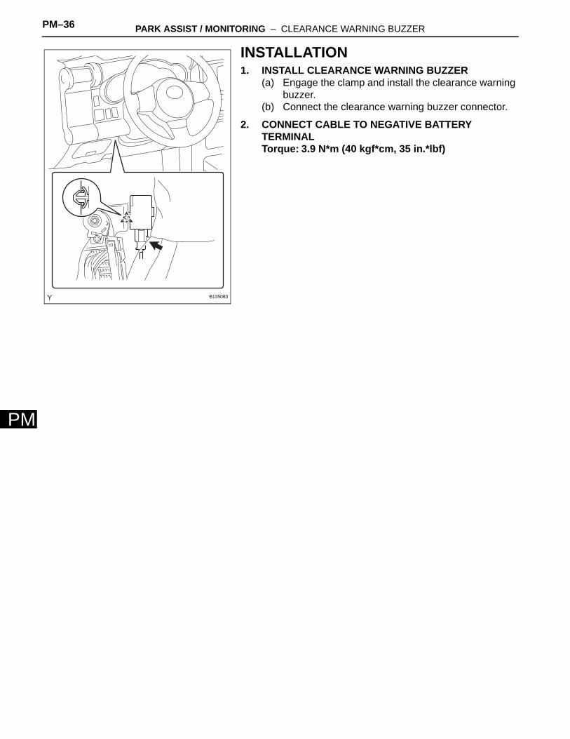
INSTALLATION1. INSTALL CLEARANCE WARNING BUZZER
(a) Engage the clamp and install the clearance warning buzzer.
(b) Connect the clearance warning buzzer connector.
2. CONNECT CABLE TO NEGATIVE BATTERY TERMINALTorque: 3.9 N*m (40 kgf*cm, 35 in.*lbf)
B135080

PARK ASSIST / MONITORING – ULTRASONIC SENSOR PM–37
M
PBODY ELECTRICALPARK ASSIST / MONITORINGULTRASONIC SENSORCOMPONENTS
REAR BUMPER
COVER
ULTRASONIC SENSOR
N*m (kgf*cm, ft*lbf) : Specified torque
3.0 (30, 27 in.*lbf)
x23.0 (30, 27 in.*lbf)
x2
8.0 (80, 71 in.*lbf)x5
WIRE to WIRE
CONNECTOR
ULTRASONIC SENSOR
CONNECTOR
WIRE to WIRE
CONNECTOR
B138491E01
PM–38 PARK ASSIST / MONITORING – ULTRASONIC SENSOR
PM
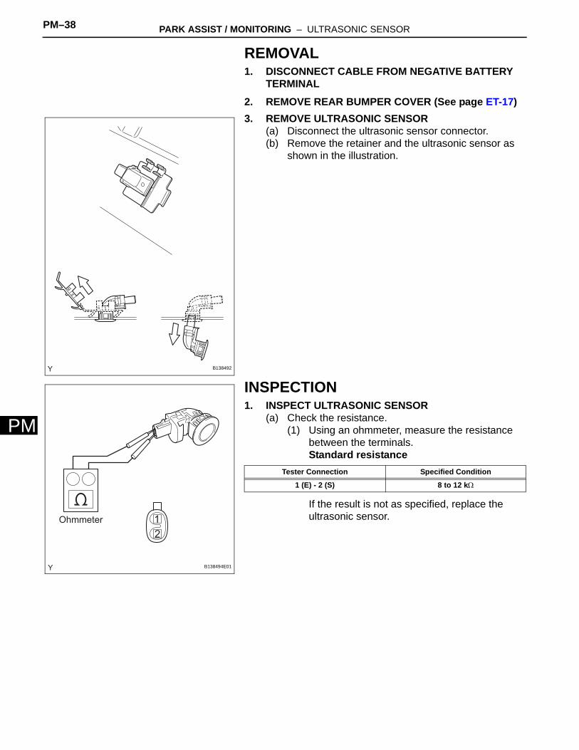
REMOVAL1. DISCONNECT CABLE FROM NEGATIVE BATTERY
TERMINAL2. REMOVE REAR BUMPER COVER (See page ET-17)3. REMOVE ULTRASONIC SENSOR
(a) Disconnect the ultrasonic sensor connector.(b) Remove the retainer and the ultrasonic sensor as
shown in the illustration.
INSPECTION1. INSPECT ULTRASONIC SENSOR
(a) Check the resistance.(1) Using an ohmmeter, measure the resistance
between the terminals.Standard resistance
If the result is not as specified, replace the ultrasonic sensor.
B138492
Ohmmeter
B138494E01
Tester Connection Specified Condition
1 (E) - 2 (S) 8 to 12 kΩ

PARK ASSIST / MONITORING – ULTRASONIC SENSOR PM–39
M
PINSTALLATIONHINT:The procedure described below is for the LH side. Use the same procedure for both the RH and LH sides, unless otherwise specified.1. INSTALL ULTRASONIC SENSOR
(a) Install the ultrasonic sensor with the retainer as shown in the illustration.
(b) Connect the ultrasonic sensor connector.
2. INSTALL REAR BUMPER COVER (See page ET-25)3. CONNECT CABLE TO NEGATIVE BATTERY
TERMINALTorque: 3.9 N*m (40 kgf*cm, 35 in.*lbf)
B138493

PM–40 PARK ASSIST / MONITORING – BACK SONAR SWITCH ASSEMBLY
PM
BODY ELECTRICALPARK ASSIST / MONITORINGBACK SONAR SWITCH ASSEMBLYCOMPONENTS
FRONT CONSOLE BOX
FRONT CONSOLE BOX
BOTTOM MAT
FRONT CONSOLE BOX UPPER
PANEL SUB-ASSEMBLY
PARKING BRAKE HOLE
COVER SUB-ASSEMBLY
SHIFT LEVER KNOB
SUB-ASSEMBLYSHIFT LEVER KNOB
SUB-ASSEMBLY
x4
SHIFT LEVER KNOB
SUB-ASSEMBLY
for Manual Transmission:for Automatic Transmission 4WD:
B135184E01

PARK ASSIST / MONITORING – BACK SONAR SWITCH ASSEMBLY PM–41
M
PBACK SONARSWITCH ASSEMBLY
BACK SONAR
SWITCH BULB
BACK SONAR
SWITCH BULB CAP
INSTRUMENT LOWER
COVER SUB-ASSEMBLY
CLIP
x2
x2
INSTRUMENT PANEL
WIRE
B138461E01

PM–42 PARK ASSIST / MONITORING – BACK SONAR SWITCH ASSEMBLY
PM
REMOVAL1. DISCONNECT CABLE FROM NEGATIVE BATTERY
TERMINAL2. REMOVE SHIFT LEVER KNOB SUB-ASSEMBLY (for
Manual Transmission) (See page IP-11)3. REMOVE SHIFT LEVER KNOB SUB-ASSEMBLY (for
4WD) (See page IP-11)4. REMOVE PARKING BRAKE HOLE COVER SUB-
ASSEMBLY (See page IP-11)5. REMOVE FRONT CONSOLE BOX UPPER PANEL
SUB-ASSEMBLY (See page IP-12)6. REMOVE FRONT CONSOLE BOX BOTTOM MAT (See
page IP-12)7. REMOVE FRONT CONSOLE BOX (See page IP-12)8. REMOVE INSTRUMENT LOWER COVER SUB-
ASSEMBLY (See page IP-13)9. REMOVE BACK SONAR SWITCH ASSEMBLY
(a) Disengage the 2 claws and remove the back sonar switch.
10. REMOVE BACK SONAR SWITCH BULB(a) Remove the back sonar switch bulb.
11. REMOVE BACK SONAR SWITCH BULB CAP(a) Remove the back sonar switch bulb cap.
B135185
B135186
B135187

PARK ASSIST / MONITORING – BACK SONAR SWITCH ASSEMBLY PM–43
M
PINSPECTION1. INSPECT BACK SONAR SWITCH ASSEMBLY
(a) Check the resistance.(1) Using an ohmmeter, measure the resistance
between the terminals.Standard resistance
If the result is not as specified, replace the back sonar switch.
(b) Check the operation.(1) Apply battery voltage to the terminals and
check that the indicator illuminates.Standard
If the result is not as specified, check the back sonar switch bulb.
2. INSPECT BACK SONAR SWITCH BULB(a) Check the resistance.
(1) Using an ohmmeter, measure the resistance between the terminals.Standard resistance:
7 to 11 Ω at 20°C (68°F)If the result is not as specified, replace the back sonar switch bulb.
INSTALLATION1. INSTALL BACK SONAR SWITCH BULB CAP
(a) Install the back sonar switch bulb cap.
Ohmmeter Battery
B135188E01
Tester Connection Condition Specified Condition
4 (ECU) - 6 (E) OFF Below 1 Ω
3 (IG) - 6 (E)ON
Below 1 Ω
4 (ECU) - 6 (E) Below 1 Ω
Condition Standard
Positive battery - Terminal 1 (ILL+)Negative battery - Terminal 2 (ILL-) Illuminates
Ohmmeter
B138462E01
B135187

PM–44 PARK ASSIST / MONITORING – BACK SONAR SWITCH ASSEMBLY
PM
2. INSTALL BACK SONAR SWITCH BULB(a) Install the back sonar switch bulb.
3. INSTALL BACK SONAR SWITCH ASSEMBLY(a) Engage the 2 claws and install the back sonar
switch.
4. INSTALL INSTRUMENT LOWER COVER SUB-ASSEMBLY (See page IP-30)
5. INSTALL FRONT CONSOLE BOX (See page IP-31)6. INSTALL FRONT CONSOLE BOX BOTTOM MAT (See
page IP-31)7. INSTALL FRONT CONSOLE UPPER PANEL SUB-
ASSEMBLY (See page IP-31)8. INSTALL PARKING BRAKE HOLE COVER SUB-
ASSEMBLY (See page IP-32)9. INSTALL SHIFT LEVER KNOB SUB-ASSEMBLY (for
4WD) (See page IP-32)10. INSTALL SHIFT LEVER KNOB SUB-ASSEMBLY (for
Manual Transmission) (See page IP-32)11. CONNECT CABLE TO NEGATIVE BATTERY
TERMINALTorque: 3.9 N*m (40 kgf*cm, 35 in.*lbf)
B135186
B135185