part 1 – general · all welding shall be performed by qualified operators. ... abrupt ridges or...
TRANSCRIPT

Seaside Aquatic Center 13150-26 11/17/2017Hoffman Estates P.D.
SECTION 13150
SWIMMING POOL
PART 1 – GENERAL
1.1 SECTION INCLUDES
A. Pool mechanical systems, including piping, circulation pump and filter.
B. Miscellaneous pool testing, safety, and control equipment as required by the Departmentof Public Health.
C. Pool start-up, closing, and instruction of Owners personnel.
1.2 REFERENCES
A. ASTM D1785 – Specification for Standard specification polyvinyl chloride (PVC) plasticpipe schedules 40, 80, and 120.
B. ASTM D1784 – Specification for Rigid Poly Vinyl Chloride (PVC) Compounds andChlorinated Poly Vinyl Chloride (CPVC) Compounds.
C. ASTM D2564 – Specifications for Solvent Cements for Poly Vinyl Chloride (PVC) PlasticPipe and Fittings.
D. ASTM D2855 – Practice for Making Solvent-Cemented Joints with PVC Pipe andFittings.
E. NSF – Seal for Potable Water.
1.3 DEFINITIONS
A. The term “pool” as used in this Section shall refer to the lap pool and activity pool.
B. The term “Architect / Engineer” as used in this Section shall refer to the pool filtrationsystem design only.
1.4 SYSTEM DESCRIPTION
A. Provide all labor and materials necessary for renovation of the existing pool filtrationsystems. The above will be complete will all equipment as indicated on the constructiondocuments. Construction shall be in accordance with State and Local Codes.
1.5 SUBMITTALS
A. Product Data: Provide Manufacturer’s/Installer’s written installation instructions.

Seaside Aquatic Center 13150-27 11/17/2017Hoffman Estates P.D.
B. The Contractor shall submit for approval to the Architect/Engineer complete lists,including descriptions catalog cuts, etc., and where applicable dimensioned shopdrawings of all material, fixtures and equipment to be furnished and installed under thisspecification. Submittal shall adequately and completely describe the equipment,including where necessary or requested complete construction and installationdimensions, complete capacity and performance data, all accessory and auxiliaryequipment, and all pertinent details of manufacture. Shop drawings for equipment shallbe submitted and approval of shop drawings shall be obtained before proceeding withfabrication. Shop drawings shall not be “doctored” reproducibles of Architects/Engineersdrawings.
C. Shop Drawings:
1. Submit shop drawings as required by Parts 2 and 3 of this Section.
2. The drawings accompanying this specification are essentially diagrammatic in natureand show the general arrangement of all equipment and piping. Because of thesmall scale of the drawings, it is not possible to show all offsets, fittings andaccessories which may be required. The Contractor shall carefully investigate thestructural and finish conditions of all his work and shall arrange such workaccordingly, furnish all fittings, pipe and accessories that may be required to meetsuch conditions. Where conditions necessitate a rearrangement, the Contractorshall obtain the Architect/Engineer’s approval. Locate all valves for maximumoperation accessibility.
D. Operation and Maintenance Manuals: Submit 4 copies of the operation and maintenancemanuals for the filter, pump and heat exchanger.
E. Required Submittals:
1. Pump, Strainer
2. Variable Frequency Drive
3. Gauges, Flow Sensors
4. Piping Materials, Valves
5. Shop Drawings:
a. Filter
6. Test Results:
a. Piping Pressure Testing
7. Guarantees Warrantees:a. Standard (1) Yearb. Filter Tank (15)
8. Close Out Documents:
Seaside Aquatic Center 13150-28 11/17/2017Hoffman Estates P.D.
a. O&M Manualsb. As Built Drawingsc. Owners Certification Of Instruction
1.6 QUALITY ASSURANCE
A. Qualifications of Pool Contractor: Work of this Section shall be performed by a contractorwho has a proven record of competence and experience in the construction of similarfacilities of this size and complexity for not less than 5 years. References will berequired by the Owner.
B. Performance Criteria: Certain sections of the Specifications contain performance criteriarather than product descriptions. It shall be the obligation of the contractor to insure thatall criteria are satisfied and the burden or proof of conformance shall rest with thecontractor. The Architect / Engineer shall require past performance records and, ifrequired, inspection trips of similar facilities to substantiate conformance with thesecriteria. The Architect / Engineer shall be sole judge of conformance. The PoolContractor is cautioned that he will be required to provide a finished product meeting allstated criteria and meeting or exceeding Department of Health requirements.
1.7 REGULATORY REQUIREMENTS
A. All applicable local building and health codes.
B. National Electrical Code (NEC)
C. National Sanitation Foundation (NSF): Seal of approval program.
D. Illinois Department of Public Health Swimming Pool and Bathing Beach Code
1.8 REQUIRED PERMITS
A. Illinois Department of Public Health by Architect / Engineer.
B. Local Building Department: Pool Contractor.
1.9 DELIVERY, STORAGE AND HANDLING
A. Deliver all materials and equipment to the Work Site in original packages fully identified,with manufacturer’s label.
B. Protect plastic pipe from exposure to chemicals (aromatic hydrocarbons, halogenatedhydrocarbons and other esters and ketones) that might attack the material. Protect allpipe from mechanical damage and long exposure to sunlight during storage.
1.10 WARRANTY
A. Warranty: Provide one (1) year warranty covering all pool workmanship, materialand equipment.
B. All standard manufacturer’s warranties shall apply to all equipment and products
Seaside Aquatic Center 13150-29 11/17/2017Hoffman Estates P.D.
provided by this Contractor.
Filter Tank shall have a fifteen (15) year warranty.
PART 2 - PRODUCTS
2.1 FILTRATION SYSTEM
A. General:
1. Purpose of the bid is to purchase and have installed a complete filtration andrecirculation system for each pool. It is intended to limit the bidding to a style ofproduct and company that has a proven history and record of performance.
2. Due to the specialized nature of certain components required for this project, thesespecifications, in some instances refer to various components by trade ormanufacturers name.
3. Whenever a proprietary (trade) name is used within this Specification Section, it isused for informational purposes to describe a standard of required function,dimension, appearance and quality. References to materials by trade name, makeor model number shall not be construed as limiting competition.
B. Quality Assurance:
1. Due to the specialized nature of the specified work and products, all bidders shall berequired to have a minimum of five (5) years of operating history. The equipmentdescribed herein shall be products of a manufacturer regularly engaged in thefabrication of filtration and circulating systems for at least fifteen (15) years and shallbe a professional engineering corporation.
2. The owner requires that filters bear the National Sanitation Foundation (NSF) seal forStandard #50. This NSF listing is required by the owner regardless of local healthdepartment regulations.
3. The specified filter system shall have had an NSF listing for at least two (2) yearsprior to the project bid date.
4. As assurance that each item of apparatus is properly sized to perform in conjunctionwith each other, the owner requires bidders to use the filter manufacturer as a singlesource of supply for the items of equipment as listed and described herewith.
5. The "EQUIPMENT SUPPLIER" shall be:
a. Neptune-Benson, Inc.; Coventry, Rhode Island; 1-800-832-8002
C. Guarantee:

Seaside Aquatic Center 13150-30 11/17/2017Hoffman Estates P.D.
1. The “EQUIPMENT SUPPLIER” shall guarantee that the equipment to befurnished is of the correct capacity, that the various parts are designed to operatecorrectly and in conjunction with each other, that if the installation is made inaccordance with the project drawings and operated in accordance with the suppliersinstructions, the system will perform the prescribed functions correctly, the waterentering the pool will be clear, bright, free from suspended matter visible to theunaided eye, and will be sanitary to the satisfaction of all authorities havingjurisdiction.
D. Filter Requirements
1. Each filter system under this section shall consist of a Defender regenerative mediafilter as detailed on the drawings or equal.
2. It is the intent of these specifications to describe a filter system complete with allaccessory items supplied and warranted by one manufacturer.
3. The primary components of the system consist of the main filter tank, flexible tubefilter elements, element assembly, bump mechanism, vacuum transfer system, sightglass, pressure gauge panel, inspection (viewing) window, valves and automaticregeneration controller.
4. All components and related subassemblies shall be factory assembled and testedprior to shipment.
E. Filter System Capacity:
1. Each system shall consist of the regenerative media filter tank(s) with a total effectivefilter surface area as shown on the drawings and operate at a rate not exceeding 1.5gallons per minute per square foot of filter area.
F. Filter Tank:
1. The filter tank shall not be less than the diameter noted on the drawings with a 60inch side shell, suitable for 50 psi working pressure and hydrostatically tested to 75psi. Tank shell shall be not less than 1/4 inch thick. Bottom dished head shall benot less than 1/4 inch thick. Top flat head shall be not less than 1 ½ inch thick. Allmaterial to be Type A-36 carbon steel. Type 304L stainless steel with no interior orexterior coatings is acceptable.
2. All welding shall be performed by qualified operators. Joints shall be butt or filletwelded inside and out by manual or automatic process. Welded joints shall havecomplete penetration and fusion with little or no reduction of the thickness of thebase metal. Welds shall be free of coarse ripples, grooves, overlaps, abrupt ridgesor valleys. All welded surfaces shall be chipped and brushed clean, whennecessary, leaving no slag or splatter.
3. Tank legs shall be constructed of 6” x 2 ½” channel legs ¼” thick. 24”, 27” and 33”filters shall have (3) legs. 41”, 49” and 55” filters shall have (4) legs. The materialshall be Type A-36 carbon steel. Bearing plates shall be 10” x 5” x ¼” type 304Lstainless steel. Each bearing plate shall have (2) 5/8” drilled holes to secure to the
Seaside Aquatic Center 13150-31 11/17/2017Hoffman Estates P.D.
floor with the ½” x 4 ½” stainless steel concrete anchors provided. The legs shall bedesigned with bolted connections to minimize overall tank heights for shipping andaccess into the mechanical room.
4. The tank head shall be bolted to the shell with 7/8 inch diameter T304 stainlesssteel studs and nuts, 9” on center around the tank perimeter.
5. Tank shall be equipped with a UL listed grounding lug.
6. Tank shall incorporate connections for filter influent, effluent and drain sizes asshowing on drawings; 1 1/2” vacuum transfer piping, 4” viewing window, and liftshaft gland.
7. Tank shall include brackets for mounting of automatic controller, gauge panel, filter /regulator, vacuum transfer blower and vacuum hose rack.
8. Tank shall include integrally mounted hydraulic lifting device (David). The DavitAssembly shall be designed to lift the filter head and include a pivot mechanismallowing the head to rotate 180° for access to tube sheet (model SP-24-42-327excludes David requirement.)
G. Flexsol 3000 interior Lining:
1. All interior surfaces shall be grit blasted to white metal condition with a 2-3 milprofile. Blasted surfaces shall be cleaned of all dust or blast residue and primed assoon as is practical on the same day blasting is done.
2. When priming has dried the lining process will begin. If prime has sat for overtwenty-four hours, a refresher coat will be applied.
3. Flexsol 3000® shall be a elastomeric polyurethane, 100 percent solid pluralcomponent lining. Hardness shall be 70 durometer on the shore D scale. Breaktensile strength shall be 24600 psi with elongation of 25-30 percent.
4. Application of Flexsol 3000® lining shall be done by experienced applicators using ahigh pressure, high temperature plural component system. All wetted surfacesincluding flange faces, manway rings and manway covers shall be lined to 120 mils+/- 5 mils DFT.
5. Hardness shall be verified after curing to ASTM D 2240 standard.
6. Flexsol 3000® lining shall meet the NSF toxicity standard unconditionally and shallbe approved for use with the NSF approved filter.
7. Flexsol 3000® lined vessels shall carry a ten (10) year limited non-proratedwarranty.
8. The filter manufacturer shall bear the responsibility for suitability of lining and shallbe the sole source for the specified warranty.
H. Exterior Coatings:

Seaside Aquatic Center 13150-32 11/17/2017Hoffman Estates P.D.
1. All exterior surfaces shall be grit blasted to white metal condition with a 2-3 milprofile. Blasted surfaces shall be cleaned of all dust or blast residue and primed assoon as practical on the same day blasting is done.
2. When priming has dried the coating process will begin. If prime has sat for overtwenty-four hours, a refresher coat will be applied.
3. Two coats of high solids enamel shall be applied for a total developed film thicknessof 5-8 mils.
4. Manufacturer is to supply min. 16 oz. of high solids enamel touch-up paint.
I. Internal Components:
1. Internally, the filter shall consist of flexible tube elements, filter assembly plate,stainless steel lift shaft and internal flow diversion assembly.
2. The filter elements shall be flexible tubes that provide the support structure for themedia. The outer wall of each element shall be fabricated of multi-filament highstrength polyester braid. Each element shall have an internal stainless steel spring,which acts a support structure for the braided filament.
3. The filter element assembly plate shall be fabricated of T304 stainless steel andprovide both support for the top of the element cluster as well as water tight seal toprevent media from escaping the filter tank.
4. The lift shaft shall be fabricated from T304 stainless steel and provide the internalconnection between the filter element assembly plate and the external bumpmechanism.
5. The filter influent connection shall be fitted with a T316 stainless steel flow diversionassembly to eliminate disturbance to the filter elements during operation.
6. All stainless steel wetted internals shall be Type 304.
J. Bump Mechanism:
1. The bump mechanism shall include a pneumatically operated tire mountedexternally on the filter tank head. The tire is alternately pressurized thendepressurized causing the connected filter element assembly to move in an upwardthen downward fashion. This movement shall provide the means of dislodging themedia and accumulated solids, which then recoat the filter element.
K. Vacuum Transfer System:
1. The vacuum transfer system shall be provided to allow the recharging of media intothe filter for either bag or bulk media.
2. The vacuum blower shall include a 1.5 h.p. (for SP-27-SP-55) or .5 h.p. (for SP-24)TEFC 115/230v single phase motor 50/60 Hz.

Seaside Aquatic Center 13150-33 11/17/2017Hoffman Estates P.D.
3. An in-line filter with dual connections shall be provided to prevent dust and mediafrom being drawn into the blower.
4. Provide three (3) 1 1/2” SCH 80 PVC ball valves: For the vacuum drain line, theblower inlet and the vacuum hose.
5. Provide 10 feet of 1 1/2” vacuum hose with fittings.
L. Automatic Controller (Alternate Only):
1. The automatic controller shall provide total control of the system's filtration andregeneration cycles, and provide all necessary equipment interlocks and timingmechanisms to execute the filter program.
2. The controller shall include an adjustable pressure switch, factory set to 50 psi. Theswitch shall stop the recirculating pump and close the pneumatic valves if airpressure falls to 50 psi.
3. The controller shall contain a microprocessor that will activate the folloing functionsof the system:
a. Bump cycle/manual or automatic.b. Precoat of filter elements.c. Stopping and starting of the main recirculating pump.d. Opening and closing of pneumatically operated valving.e. Vacuum transfer system.f. Heater cool down delay.g. Auxiliary contacts to interlock chemical control or other equipment.h. Keyed switch to activate a continuous, intermittent bump cycle for flex tube
cleaning.
4. The controller panel shall display the following function:
a. Filter status.b. Precoat status.c. Recirculating pump status.d. Vacuum transfer pump status.e. System power.
5. The controller enclosure shall be NEMA 12.
6. The RMF automatic controller will provide signal power to the main recirculatingpump motor starter. The unit is required to be a device or variable frequency drive(VFD) and is to be installed with control wiring by the electrical contractor.
7. The RMF shall be 120v, 1-phase, 30 amp rated and shall be UL labeled
M. Flow meter:
Seaside Aquatic Center 13150-34 11/17/2017Hoffman Estates P.D.
1. A digital flow meter shall be included with a 4-20mA 0-10 VDC analog output.
2. The flow meter shall be wired into the VFD to provide automatic speed control of thefilter pump motor.
3. The VFD shall compensate for varying filter head losses by maintaining the specifiedflow rate with the 4-20mA output signal of the flow meter.
N. Filter/Regulator:
1. Each filter shall include a combination filter / regulator. The regulator shall beadjustable from 0 – 120 psi. 1/2 inch F.P.T. connections shall be provided for fieldinstallation of air lines.
O. Water Separator:
1. One water separator with automatic drain shall be included for each air compressorsupplied. 1/2 inch F.P.T. connections shall be provided for field installation of airlines.
P. Air compressor:
1. The system will require (1) air compressor per mechanical room that shall include:
a. 30 gallon tankb. 2 HP, electric motor 120v, 1 phase, 15 amp.c. Air pressure gauge.d. Pressure relief valve.e. Belt guard.f. Pressure switch.g. Air filter.h. 5.5 CFM @ 90 psi.
Q. Pneumatic Actuators:
1. Each filter shall include pneumatic actuators for (1) check valve, (1) effluent valveand (1) precoat valve.
2. The actuators shall be double acting with valve mounted drilling to ISO 5211.
3. The actuators shall include (2) 1/4 inch FPT ports for open / close connections. Flowcontrol valves with quick connect fittings shall be provided at each port to allowspeed control adjustment for the open / close function of the actuators.
4. Materials of Construction
a. Body: aluminum alloy, extruded acc. To ASTM 6063, anodized acc. To UNI4522.
b. Ends: Die-cast in aluminum alloy acc. To ASTM B179, epoxy-polyester coated.c. Pistons: Die-cast in aluminum alloy acc. To ASTM B179.
Seaside Aquatic Center 13150-35 11/17/2017Hoffman Estates P.D.
d. Pinion: Nickel-plated steel.e. Slideways: Acetal resin (LAT LUB 731320T).f. Fasteners: AISI 304 Stainless steel.g. Springs: Epoxy coated steel, pre-compressed.h. Seals: NBR Nitrile rubber.i. Lubricant: MoS2.
R. Solenoid Valve:
1. Each filter shall include pneumatic actuators for (1) check valve, (1) effluent valve and(1) precoat valve.
2. The solenoid valves shall include lighted DIN connectors.
3. The solenoid valves shall be factor lubricated and shall not require any fieldlubrication.
4. The solenoid valves with multi-station manifold shall be located on the bottom of theautomatic controller, factory wired and include quick connect fittings for attachmentto the pneumatic actuators and bump mechanism.
5. The solenoid valves shall be SMC Series SY 7000.
S. Valves:
1. All Valves 3 inches – 12 inches shall be constructed with cast aluminum ASTM SI2Ahousing and fully coated with Rilsan on all interior and exterior surfaces. Internalcomponents include EPDM resilient lining, Rilsan coated ductile iron disc and T304stainless steel shaft. Valves 14 inches and larger shall be constructed with cast ironhousing fully coated with nylon and nylon coated ductile iron disc.Valves shall be butterfly valves and shall be provided for the influent, effluent andprecoat lines.
T. Media:
1. Media shall be expanded perlite with a median particle size of 37 microns.Percentage retained on a +150 Tyler Mesh shall not be less than 8% or more than25%. Darcy permeability shall be between 1.2-1.85.
2. The media shall contain no more than 1 tenth of one percent (.001) or crystallinesilicate.
3. The media shall be certified by the manufacturer for use in the Defender Filter. Themedia shall be NSF listed in Std. 61 and Std. 50.
4. The media shall be Celaperl 1400P as supplied by EP Minerals.
U. Warranty:
1. Defender filter tanks with Flexsol 3000 shall carry a 10 year fully rated warranty asregularly offered by the tank manufacturer.

Seaside Aquatic Center 13150-36 11/17/2017Hoffman Estates P.D.
2. Bump tire and internal tube elements shall carry a fully rated 3 year warranty.
3. Valve bodies shall carry a 5 year fully rated warranty.
4. Valve operators and system accessories including the RMF controller, quick exhaustvalve and solenoid valve shall carry one year warranty as provided by the productmanufacturer.
5. Unless otherwise specified, workmanship is to be guaranteed first class and carry aone (1) year warranty.
2.2 WATER TREATMENT SYSTEM
A. Re-install existing chemical system as shown and scheduled on Contract documents.All in accordance with manufacturer’s recommendations.
B. Furnish Owner with written water treatment program complete with written basic waterchemical analysis and verbal instructions as to operate of system.
2.3 PUMPS [FLOODED SUCTION]
A. Furnish and install circulation pumps as manufactured by Marlow, Sulzer/Paco, Auroraor approved equal. See contract documents for horsepower, voltage, phase, flow rate,NPSH-A, pump and motor efficiency, VFD, flow meter and pipe size information.
B. Furnish and install pressure and vacuum gauges where called for on Drawings and asrequired by Code. Pressure and vacuum gauges shall be Trerice #700 Liquid Filled, 0-60 PSI, vacuum 30 Hg – 30 PSI, all gauges with gauge cocks.
C. To insure cavitations-free operation, each pump’s NPSH requirements must be lowenough to permit stable, continuous operation at 120 percent or greater of bestefficiency point.
D. Pump casing shall be close grain cast iron fitted with a replacement bronze case wearring. Minimum 1/4 inch NPT suction and discharge gauge taps. Pumps with a specificspeed greater than 1600 shall have double volute casings with suction splitter to reduceradial loading and shaft deflection.
E. Pump impeller shall be of the enclosed type of cast bronze, lead free, zinc free,aluminum bronze and shall be statically and dynamically balanced. Impeller diametershall be trimmed for the specified design conditions.
F. Pumps mounted vertically to have recirculation line pipe from seal cavity to suction of thepump.
G. Pumps to be mounted on a cast iron fabricated steel base, epoxy coated, and stainlesssteel hardware.
H. Pump shall be fitted with a leakless mechanical seal. John Crane type 1 BUNAelastomers ceramic stationary seat carbon rotating stainless steel metal parts.
Seaside Aquatic Center 13150-37 11/17/2017Hoffman Estates P.D.
I. Shaft to have a replaceable lead free, zinc free, bronze shaft sleeve.
J. Pump to have an epoxy coating on all interior cast iron parts. All pump fasteners to be300 series stainless steel and should have a never seize application to threads prior toassembly , or approved equal.
K. Pump motor to 3-phase, 60 cycle, Totally Enclosed Fan Cooled, with horse power andvoltage as shown on drawings, 1.15 service factor, inverter duty, NEMA (MG-1) sectionIV, Part 30.2.2.8, 200v or 208v motor must be single voltage, tri-voltage motor notacceptable on 200v or 208v service.
L. All pumping components capable of pumping heavy chlorinated pool water.
2.4 STRAINERS
A. Furnish and install hair and lint strainers where call for on drawings. Strainers to be ofPVC or stainless steel construction with a clear acrylic lid as manufactured by NeptuneBenson or Paddock Pool Equipment Co., Inc. Strainers shall be of the reducing type.
B. Strainer baskets shall be stainless steel construction with 5/32 inch perforations.Provide each strainer with two strainer baskets.
2.5 VARIABLE FREQUENCY DRIVES
A. The Variable Frequency Drives (VFD’s) shall employ a Pulse Width Modulated (PWM)output waveform. Drive efficiency shall be 97% or better at full speed/load. The samemanufacturer shall supply the Variable Frequency Drives for both Feature and Filterpumps. The Pump Supplier shall be responsible for providing as a system, the pumps,VFD’s, flow meter and the set-point controller.
B. The VFD shall be manufactured by Benshaw SG series, ABB, Model ACH 550,Square D Altivar Model 61 or approved equal. All items in this specification must beadhered to strictly. Any deviation must be submitted and approved in writing tenworking days prior to bid date.
1. This specification is to cover a complete Variable Frequency motor Drive (VFD)consisting of a pulse width modulated (PWM) inverter designed for use on a standardNEMA Design B induction motor.
2. The drive manufacturer shall supply the drive and all necessary options as hereinspecified. VFD’s that are manufactured by a third party and “brand labeled” shall notbe acceptable. All VFDs installed on this project shall be from the samemanufacturer.
3. VFD’s with Filter Packages will include: Non-fused main disconnect, chemical pump,Heater, inter lock relay, Backwash Timer, Filter Alarm light on door Auto/OffBackwash Selector Switch, and 115V Control Transformer.
4. Drives to operate automatically with a 4 to 20 ma PID loop with the flow meter andshow actual flow rate in GPM on the keypad.

Seaside Aquatic Center 13150-38 11/17/2017Hoffman Estates P.D.
5. With a certified start up you will receive a 2-year warranty on all parts and labor.
C. Reference Standards:
1. Standar 519-1992, IEEE Guide for harmonic content and control
2. UL508C
3. ICS 7.0, AC Adjustable Speed Drives
4. IEC 16800 Parts 1,2 and 3
5. NEC 430.120, Adjustable-Speed Drive Systems
6. IBC 2006 Seismic-referencing ACS 7-05 and ICC AC-156
D. Qualifications:
1. VFDs and options shall be UL listed as assembly. The base VFD shall be UL listedfor 100 KAIC without the need for input fuses.
2. CE Mark – The VFD shall meet product standard EN 61800-3 for the FirstEnvironment restricted level. (RFI / EMI Filter spec).
3. The entire VFD enclosure, including the bypass shall be seismically certified andlabeled in accordance with the IBC 2006 International Building Code:
a. VFD manufacturer shall provide Seismic Certification and Installationrequirements at time of submittal.
b. Seismic importance factor of 1.5 rating is required, and shall be based uponactual shake test data as defined by ICC AC-156.
c. Seismic ratings based upon calculations alone are not acceptable. Certification ofSeismic rating must be based on testing done in all three axis of motion by acertified lab.
E. Submittals shall include the following information:
1. Outline dimensions, conduit entry locations and weight.
2. Customer connection and power wiring diagrams.
3. Complete technical product description including a complete list of options.
4. Compliance to IEEE 519 – harmonic analysis for particular jobsite including totalharmonic voltage distortion and total harmonic current distortion (TDD).
a. The VFD manufacturer shall provide calculations; specific to this installation,showing total harmonic voltage distortion is less than 5% impedance reactors, noexceptions.

Seaside Aquatic Center 13150-39 11/17/2017Hoffman Estates P.D.
F. The VFD Package as specified herein shall be enclosed in a UL Listed Typeenclosure, (enclosures with only NEMA ratings are not acceptable.)
1. Environmental operating conditions: 0 to 400 C (32 to 1040 F) continuous. Altitude 0to 3300 feet above sea level, less than 95% humidity, non-condensing. All circuitboards shall have conformal coating.
2. Enclosure shall be UL rated and shall be UL listed as a plenum rated VFD.
G. All VFDs shall have the following standard features:
1. All VFDs shall have the same customer interface, including digital display, andkeypad, regardless of horsepower rating. The keypad shall be removable, capable ofremote mounting and allow for uploading and downloading of parameter settings asan aid for start-up of multiple VFDs.
2. The keypad shall include Hand-Off-Auto selections and manual speed control. Thereshall be fault reset and “Help” buttons on the keypad. The Help button shall include“on-line” assistance for programming and troubleshooting.
3. The VFD shall have internal 5% impedance reactors to reduce the harmonics to thepower line and to add protection from AC line transients.
4. The input current rating of the VFD shall be no more than 3% greater than the outputcurrent rating. VFD’s with higher input current ratings require the upstream wiring,protection devices, and source transformers to be oversized per NEC 430.120.
5. The VFD shall provide a programmable loss-of-load (broken belt / broken coupling)Form-C relay output. The drive shall be programmable to signal the loss-of-loadcondition via a keypad warning, Form-C relay output, and / or over the serialcommunications bus.
H. Serial Communications
1. The VFD shall have an EIA-485 port as standard. The standard protocols shall beModbus, Johnson Controls N2, Siemens Building Technologies FLN, and BACnetMS/TP. The use of third party gateways and multiplexers is not acceptable. Allprotocols shall be “certified” by the governing authority (i.e. BTL Listing for BACnet).
I. EMI / RFI filters. All VFD’s shall include EMI/RFI filters. The onboard filters shallallow the entire VFD assembly to be CE Marked and the VFD shall meet productstandard EN 61800-3 for the First Environment restricted. No Exceptions.
J. OPTIONAL FEATURES – Optional features to be furnished and mounted by the drivemanufacturer. All optional features shall be UL Listed by the drive manufacturer as acomplete assembly and carry a UL508 label.
2.6 POOL VALVES AND PIPING MATERIALS

Seaside Aquatic Center 13150-40 11/17/2017Hoffman Estates P.D.
A. Products:
1. Provide valves of same manufacturer throughout where possible and practical.
2. Provide valves with manufacturer’s name and pressure rating clearly marked onoutside of body.
B. Valve Connections: Provide valves suitable to connect to adjoining piping as specifiedfor pipe joint. Use pipe size valves.
C. Use of Valves:
1. Pipe sizes 3” – 12”, Butterfly.
2. Miscellaneous valves ½” – 2”, PVC True Union Ball Valves.
3. All chemical lines and equipment – PVC True Union Ball Valves.
D. Butterfly Valves:
1. Butterfly valves 3” – 12” shall be wafer or lug bodies and shall be suitable for usebetween ANSI 125 or 150 lb. Flanges.
2. Bodies of the flangeless design shall be provided with at least four (2) bolt guides tocenter the valve in the pipeline.
3. All butterfly valves shall have a cast iron body epoxy coated, ductile iron nylon 11coated discs, stainless shaft with Buna-N or EPDM seat minimum 150 PSI rating.
4. All butterfly valves 4” – 6” shall have 10 position locking handle, butterfly valves 8” –12” shall have gear operators and chain operators as required.
5. All valves shall be as manufactured by Bray Valve (713) 894 5454 or equal asapproved by the Architect / Engineer.
E. Ball Valves:
4. PVC True Union Ball Valves, Dual Union, Eslon, Assahi, or equal.
F. Check Valves – (where required): Shall be cast iron body, stainless steel spring trim,bronze split disc, seal material Buna-N. (CHEXX) Model as manufactured by Metraflex,Chicago, Illinois, or Mueller Steam Specialties as indicated on Contract documents.
F. Modulating Float Valves: Shall be used in the surge tank as specified on Contractdocuments. The valves shall be constructed with stainless steel rods and PVC floatsallowing 20% maximum flow when fully closed. As manufactured by Neptune Benson orequal as approved by the Architect / Engineer.
PART 3 – EXECUTION

Seaside Aquatic Center 13150-41 11/17/2017Hoffman Estates P.D.
3.1 PIPING AND PIPE FITTINGS – HANGERS AND SUPPORTS
A. Work Included: Pipe, fittings, connections, wall penetrations, hangers and supports,equipment bases and supports.
B. Use the prescribed pipe type in the following areas. All plastic pipe flanges shall bescheduled 80 PVC with neoprene gaskets where required.
1. All piping shall be schedule 80 or pressure rated PVC solvent weld.
2. All chemical piping, schedule 80 PVC, solvent weld.
3. Heater connections shall be Type “L” copper piping on the heater influent andeffluent lines from the bypass to the heater, with cast brass or wrought copper fittingand 95/5 soldered joints.
C. Hangers and Supports: Submit hanger locations and weights, hanger details on ShopDrawings.
1. All mechanical room piping must be properly supported.
2. It shall be the Contractor’s responsibility to properly support piping at all valves,pumps, equipment, overhead areas, etc.
3. Use of the proper hanger for the conditions is essential. All piping must besupported laterally as well as vertically hung.
4. All piping 8” or larger must be properly supported from the floor only.
5. All piping connections and support hardware shall be stainless steel inside balancetanks.
D. Piping:
1. Cut all pipe with mechanical cutter without damage to pipe.
2. Placing and laying: Inspect pipe for defects before installation. Clean the interior ofpipe thoroughly of foreign matter and keep clean during laying operation.
3. Threaded joints: After cutting and before threading, the pipe shall be reamed andshall have burrs removed. Screw joints shall be made with graphite or inert filler andoil or with an approved graphite compound applied to make threads only. Threadsshall be full-cut and not more than 3 threads on the pipe remained exposed. UseTeflon II tape on the make threads of all threaded pipe joints. Caulking of threadedjoints to stop or prevent leaks will not be permitted. Unions shall be provided whererequired for disconnection of exposed piping. Unions will be permitted where accessis provided
4. Solvent welded joints shall be made in accordance with the manufacturer’s printedinstructions and the following minimum standards:
Seaside Aquatic Center 13150-42 11/17/2017Hoffman Estates P.D.
a. All fittings shall fit easily on the pipe before applying cement. The outer surfacearea of pipe and inner wall of fitting shall be dry and clean. Cleaner is to beapplied to the outer surface of the pipe and to the inner surface of the fitting.Cement is to be applied to the outer surface of the pipe, or on the male section offittings only. When the outside surface area of the pipe is satisfactorily coveredwith cement allow ten (10) seconds open time to lapse before inserting pipe endinto fittings. After full insertion of pipe into fitting, turn fitting around the pipe endapproximately 1/8 to ¼ of a turn. Wipe off excess cement at the joint in a neatcove bead. Follow manufacturer’s instructions on solvents.
b. All joints shall remain completely undisturbed for a minimum of 10 minutes fromtime of jointing the pipe and fitting. If necessary to apply pressure to a newlymade joint, limit to 10% of rated pipe pressure, during the first 24 hours after thejoint has been made.
c. Full working pressure shall not be applied until the joints have set for aperiod of 24 hours.
5. Make provisions for expansion and contraction by way of swing joints or snaking.
E. Protect plastic pipe from exposure to aromatic hydrocarbons, halogenated hydro-carbons, and most of the esters and ketones that attack the material. Protect all pipefrom mechanical damage and long exposure to sunlight during storage.
F. No installation shall be made that will provide a cross connection or interconnectionbetween distribution supply for drinking purposes and the swimming pool that will permita backflow of water into the potable water supply. Pipe openings shall be closed withcaps or plugs during installation. Equipment and pool fittings shall be tightly coveredand protected against dirt, water and chemical or mechanical injury. At the completionof work the fittings, materials and equipment shall be thoroughly clean and adjusted forproper operation.
G. Pipe Identification
1. Provide identification on all piping located in mechanical equipment, chlorine, acidrooms, heater courts, etc.
2. Identify the pool that the line is serving (with multiple pools only), contents, directionof flow.
3. Mark at least once on each line and at 20 ft. intervals on long pipe runs. ConsultHealth Department Code form minimum marking requirements.
4. Color code per Health Department requirements. If code does not identify colorcoding requirements consult Architect/Engineer.
5. Brady, B-946, custom legend, self-sticking markers and arrows or equal.
3.2 TESTING/FIELD QUALITY CONTROL
A. This Section requires the following tests to be performed by the Contractor.
Seaside Aquatic Center 13150-43 11/17/2017Hoffman Estates P.D.
B. Testing and Flushing of Piping:
1. Contractor shall be responsible for discovering leaks and making necessary repairs.
2. After the piece is installed, the joints completed, test all pool piping per the IllinoisPlumbing Code, Section 890.1930, Test Methods. Joints shall remain airtight underthis pressure for a period of twelve hours. Provide test results to the Architect /Engineer.
3. Leaks shall be repaired and tested repeatedly until leakage or infiltration is approved.
C. Water Treatment:
1. Obtain a chemical analysis of the source/pool make-up water supply and submit toArchitect / Engineer. Include the following:
a. Total alkalinity / PPMb. Calcium hardness / PPMc. Chlorine / PPMd. PHe. Ironf. Copper
2. Treat and balance pool water prior to turnover of pool to the Owner (using chemicalsprovided by the Owner).
3. Pool water: balance to establish a total alkalinity level of 60-125 PPM and calciumhardness level of 180-375 PPM (3 times alkalinity level).
4. Stabilize pool water by shocking to 20 PPM of chlorine for initial sanitation.
5. Consult with Architect / Engineer for special waters to establish balanced levels.
3.3 INSTRUCTION OF OWNER’S PERSONNEL
A. The Pool Sub-contractor shall supply the services of an experienced swimming pooloperator instructor for a period of not less that four (4) hours after the pool has beenfilled and initially placed in operation. During this period the Owner’s designatedrepresentatives shall be thoroughly instructed in all phases of the pool’s operation.
B. Prior to this instructor leaving the job, he shall obtain written certification from theOwner’s designated representative acknowledging that the instruction period has beencompleted and all necessary operating information provided.
C. Pool Sub-contractor shall deliver two complete sets of operating and maintenanceinstructions for the swimming pool equipment to the Architect / Engineer. Including, butnot limited to the following:
1. Bound together in a complete manual.
Seaside Aquatic Center 13150-44 11/17/2017Hoffman Estates P.D.
2. Accurate parts list.
3. Pool start-up instructions.
4. Narrative on the pool operation through all sequences.
5. All valves must be permanently tagged along with valve legend and explanation.
6. Trouble shooting information.
7. A schematic piping diagram as installed.
8. All piping in Mechanical Room to be labeled with description of line an arrowsindicating direction of flow.
3.4 CLEAN UP AND PROTECTION
A. After work of this Section has been complete, clean up work areas and remove allequipment excess materials and debris. Protect pool from damage until time of FinalAcceptance. Remove and replace finishes that are chipped, cracked, abraded,improperly adhered, or otherwise damaged.
END OF SECTION
SP-1
EXISTING FILTER
EQUIPMENT LAYOUT
JOB NO.
RRD / TJMDRAWN BY:
A17269
#
DATE: 11.16.17
REVISIONDATE
DESCRIPTION:
HO
FF
MA
N E
ST
AT
ES
PA
RK
DIS
TR
IC
T
13
00
MO
ON
LA
KE
BL
VD
.
HO
FF
MA
N E
ST
AT
ES
, I
L 6
01
69
SE
AS
CA
PE
AQ
UA
TIC
I N
N
O
V
A
T
I V
E
AQ
UA
TIC
DE
SIG
N, L
LC
16
85
W. H
IG
GIN
S R
OA
D
HO
FF
MA
N E
ST
AT
ES
, I
L 6
01
69
(8
47
) 8
85
-75
00
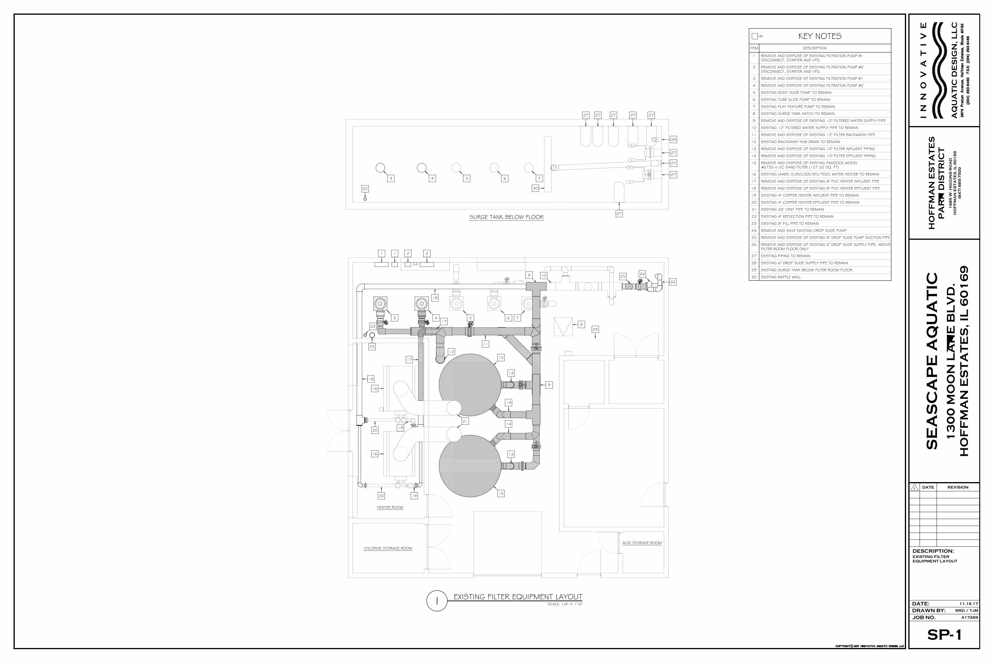
EXISTING FILTER EQUIPMENT LAYOUT1 SCALE: 1/4" = 1'-0"
20 19
16
16
1920
18
23
22
17
3 417
18
5 6
829
9 10 25 24
26
13
14
13
14
15
15
9
12
21
1 1 2 2
11
7
SURGE TANK BELOW FLOOR
3 4 5 6 7
30
27 27
28
22
27 27 27
27
27
27
27
CHLORINE STORAGE ROOM
HEATER ROOM
ACID STORAGE ROOM
KEY NOTESDESCRIPTIONITEM
1
2
3
4
5
6
7
8
9
10
11
12
13
14
15
REMOVE AND DISPOSE OF EXISTING FILTRATION PUMP #1
REMOVE AND DISPOSE OF EXISTING FILTRATION PUMP #2
EXISTING BODY SLIDE PUMP TO REMAIN
EXISTING TUBE SLIDE PUMP TO REMAIN
EXISTING PLAY FEATURE PUMP TO REMAIN
REMOVE AND DISPOSE OF EXISTING PADDOCK MODEL#6735-V-2C SAND FILTER (127.22 SQ. FT)
EXISTING SURGE TANK HATCH TO REMAIN
REMOVE AND DISPOSE OF EXISTING 12" FILTER BACKWASH PIPE
REMOVE AND DISPOSE OF EXISTING 10" FILTER INFLUENT PIPING
REMOVE AND DISPOSE OF EXISTING 10" FILTER EFFLUENT PIPING
REMOVE AND DISPOSE OF EXISTING 8" PVC HEATER EFFLUENT PIPE
REMOVE AND DISPOSE OF EXISTING 8" PVC HEATER INFLUENT PIPE
EXISTING LAARS 3,050,000 BTU POOL WATER HEATER TO REMAIN
EXISTING 26" VENT PIPE TO REMAIN
REMOVE AND DISPOSE OF EXISTING FILTRATION PUMP #2DISCONNECT, STARTER AND VFD.
EXISTING 4" COPPER HEATER INFLUENT PIPE TO REMAIN
EXISTING BACKWASH HUB DRAIN TO REMAIN
EXISTING 12" FILTERED WATER SUPPLY PIPE TO REMAIN
REMOVE AND DISPOSE OF EXISTING FILTRATION PUMP #1DISCONNECT, STARTER AND VFD.
REMOVE AND DISPOSE OF EXISTING 12" FILTERED WATER SUPPLY PIPE
16
EXISTING 4" COPPER HEATER EFFLUENT PIPE TO REMAIN
17
18
19
20
21
EXISTING 4" REFLECTION PIPE TO REMAIN22
EXISTING 8" FILL PIPE TO REMAIN23
REMOVE AND SAVE EXISTING DROP SLIDE PUMP24
REMOVE AND DISPOSE OF EXISTING 8" DROP SLIDE PUMP SUCTION PIPE25
REMOVE AND DISPOSE OF EXISTING 6" DROP SLIDE SUPPLY PIPE, ABOVEFILTER ROOM FLOOR ONLY
26
EXISTING PIPING TO REMAIN27
EXISTING 6" DROP SLIDE SUPPLY PIPE TO REMAIN28
EXISTING SURGE TANK BELOW FILTER ROOM FLOOR29
EXISTING BAFFLE WALL30

SP-2
NEW FILTER
EQUIPMENT LAYOUT,
EQUIPMENT LIST,
DETAILS AND NOTES
JOB NO.
RRD / TJMDRAWN BY:
A17269
#
DATE: 11.16.17
REVISIONDATE
DESCRIPTION:
HO
FF
MA
N E
ST
AT
ES
PA
RK
DIS
TR
IC
T
13
00
MO
ON
LA
KE
BL
VD
.
HO
FF
MA
N E
ST
AT
ES
, I
L 6
01
69
SE
AS
CA
PE
AQ
UA
TIC
I N
N
O
V
A
T
I V
E
AQ
UA
TIC
DE
SIG
N, L
LC
16
85
W. H
IG
GIN
S R
OA
D
HO
FF
MA
N E
ST
AT
ES
, I
L 6
01
69
(8
47
) 8
85
-75
00
NEW FILTER EQUIPMENT LAYOUT1 SCALE: 1/4" = 1'-0"
2
M
N
JNM2 3
K
11
10
15
7 7
18
18
O
O 25
P
16
SURGE TANK BELOW FLOOR
NOTE:POOL CONTRACTOR TO VERIFYFILTER OVERHEAD CLEARANCESPRIOR TO FILTER INSTALLATION,FINAL LOCATIONS TO BEDETERMINED IN FIELD.
7
H
H
7
4
4
A
A
7
78
14
14
19
6
6
5
B
B
19
19
C
C
18
18
23 23
10
20 21
11
13
13 12
12
9
9
19
17
15
D
1632
12
E
E
L
22
ACID STORAGE ROOMCHLORINE STORAGE ROOM
HEATER ROOM
ACID STORAGE ROOM
KEY NOTESDESCRIPTIONITEM
1
2
3
4
5
6
7
8
EXISTING SURGE TANK HATCH
NEW 10" FILTER INFLUENT PIPING
NEW 10" FILTER EFFLUENT PIPING
NEW 8" CPVC HEATER EFFLUENT PIPE
NEW 8" CPVC HEATER INFLUENT PIPE
EXISTING LAARS 3,050,000 BTU POOL WATER HEATER
EXISTING 26" VENT PIPE
CONENCT TO EXISTING 4" COPPER HEATER INFLUENT PIPE
EXISTING BACKWASH HUB DRAIN, CUT FLUSH WITH FLOOR
CONNECT TO EXISTING 12" FILTERED WATER SUPPLY PIPE
NEW 12" FILTERED WATER SUPPLY PIPE
9
CONNECT TO EXISTING 4" COPPER HEATER EFFLUENT PIPE
10
11
12
13
14
PROVIDE CLEARANCE FOR FILTER TOP REMOVAL
NEW FILTER AIR COMPRESSOR
CAP EXISTING 8" PIPE15
NEW 8" DROP SLIDE PUMP SUCTION PIPE16
NEW 6" DROP SLIDE SUPPLY PIPE, CONNECT TO EXISTING17
NEW 12" FILTRATION PUMP SUCTION PIPE18
NEW 6" FILTER PRECOAT PIPE19
NEW 4" REFLECTION PIPE, EXTEND AWAY FROM PUMP SUCTION PIPES20
EXISTING 8" FILL PIPE21
FILL EXISTING PENETRATION WITH LIGHT-WEIGHT, NON-SHRINK CONCRETE23
REINSTALL EXISTING DROP SLIDE PUMP22
G 3700TRERICEPRESSURE GAUGE, 0 - 60 PSI, 2 1/2" DIAL, LIQUID FILLED, WITHSTAINLESS STEEL TUBE AND SOCKET, SNUBBER NO. 872-2 ANDGAUGE COCK NO. 865MFG.
VACUUM GAUGE, 0" - 30", 2 1/2" DIAL, LIQUID FILLED, WITHSTAINLESS STEEL TUBE AND SOCKET, SNUBBER NO. 872-2 ANDGAUGE COCK NO. 865MFG.
3700TRERICEF
2VARIABLE FREQUENCY DRIVE, 208/230 VOLT, 3-PH, 60 Hz, W/NEMA 3 ENCLOSURE AND COOLING FAN, INTEGRAL DISCONNECTAND LINE REACTOR, VERIFY VOLTAGE AND HORSEPOWER FORMOTOR BEFORE ORDERING.
E
PVC ANTI-VORTEX PLATE, 12" CONNECTION, 36" DIAMETER PLATE. NEPTUNE BENSON AVPLATE12PVCKIT 2
FILTRATION PUMP AND MOTOR, FLOODED SUCTION, 1,460 G.P.M. @80 FT. TDH, 40 H.P., 208/230 VOLT, 3-PHASE,1750 RPM, W/ EPOXYCOATING ON ALL INTERIOR CAST IRON PARTS.
B
FILTER, REGENERATIVE "PERLITE" MEDIA, W/ 1,211 SQ. FT. OF FILTERAREA, 1.20 G.P.M. / SQ. FT. OF FILTER AREA FILTRATION RATE, STEELTANK W/ CONTROL PANEL, AIR COMPRESSOR, MEDIA VACUUMTRANSFER SYSTEM AND PNEUMATIC VALVES.
2
2
SP-49-48-1548
60123 LC
CATALOG NO. QTY.
PACO
A
ITEM DESCRIPTION
NEPTUNE BENSON
MANUFACTURER
NEW FILTRATION EQUIPMENT LISTTHE EQUIPMENT MANUFACTURERS AND CATALOG NUMBERS LISTED BELOW, AND NOT SPECIFICALLYMENTIONED IN THE SPECIFICATIONS, ARE SHOWN TO PROVIDE A STANDARD. EQUIPMENT BY OTHER
MANUFACTURERS WILL BE APPROVED IF SAID EQUIPMENT IS SHOWN TO BE EQUAL TO THAT SPECIFIED.
NEPTUNE BENSON 1500NBFG12R1 2C STRAINER, FIBERGLASS, 12" W/ TWO STAINLESS STEEL BASKETS.
ACS550 SERIESABB
O
SWITCHING POWER SUPPLY, 110 VOLT, 1-PHASE, 4.2 AMP OUTPUTCAPACITY AT 24 VOLTS.
SIGNET 7300-1024 1K
NEPTUNE BENSON 1500NBFG84R1 1D STRAINER, FIBERGLASS, 8" X 4" W/ TWO STAINLESS STEEL BASKETS.
PVC ANTI-VORTEX PLATE, 8" CONNECTION, 18" DIAMETER PLATE. NEPTUNE BENSON AVPLATE8PVCKIT 1P
THERMOMETER, 30° TO 130° FAHRENHEIT RANGE WITH SEPARABLE WELLNO. 138-0015.2.
2A40543TRERICEM
MAGNETIC FLOW SENSOR, 10", FOR FILTRATION PUMP AND MOTORVARIABLE FREQUENCY DRIVE CONTROL.
H 23-2551-P1-12SIGNET
L AUTOMATIC WATER LEVEL CONTROLLER, W/ ELEVEN POLE BASE MODEL#ZPD11, PROBES MODEL #A94-10 & MOISTURE PROOF ENCLOSUREMODEL #C1-C, 115 VOLT, 1-PHASE.
CARLOS GAVAZZI S194-156-115 1
MAGNETIC FLOW SENSOR, W/ INTEGRAL DISPLAY, 12".J 3-2551-P1-42 1SIGNET
AQUASTAT, SET TO 115° FAHRENHEIT. HONEYWELL L4006A1959 2N
DATAFILTER FLOWRATE:
TOTAL
2,920 G.P.M.
NEW TYPICAL PUMP DETAIL2 SCALE: 1/2" = 1'-0"
1
0
NEW 12" PUMPSUCTION PIPE
SURGE TANK
C
5
4
1
2F
B
NEW CONCRETEEQUIPMENT PADAS REQUIRED
NEW 10" FILTRATIONPUMP DISCHARGEPIPE (TYP. 2)
NEW 6" FILTERPRECOAT PIPE
USE 45° ELL'S ONLYLONG RADIUS BASEELBOW, CAST IRONAND EPOXY COATED
NOTES:1.) VFD TO BE PROGRAMMED TO
SHUT-DOWN PUMP IF NO FLOW DETECTED
2.) SEE SP-3 FOR VALVE LEGEND
FILTER ROOM FLOOREXISTING 8" FILL PIPE
EXISTING 4" REFLECTIONPIPE FOR WATER LEVELCONTROLLER PROBES
EXISTING FRESH WATERFILL PIPE
GATE VALVE
1" GATE VALVE
1" SLOW-CLOSING SOLENOIDVALVE W/ WIRING TO CONTROLLER
1" GATE VALVE
WIRING TO WATER LEVELCONTROLLER PROBE
TYPICAL WATER LEVEL CONTROLLER3 SCALE: 1" = 1'-0"
G.F.C.I. PROTECTED POWER SUPPLY,115 VOLT, 1-PHASE
L
DEEP HOPPER MAIN DRAIN NOTES:
1. THE EXISTING DEEP HOPPER UNBLOCKABLE 1'-11" X 15'-11" MAIN DRAIN WITH (10) 18" X 18" GRATES IN A CUSTOMSTAINLESS STEEL FRAME MEETS ANSI/APSP 16.
2. THE EXISTING DEEP HOPPER UNBLOCKABLE SUBMERGED SUCTION OUTLET HAS (2) 12" PIPES. THE TWO 12" PIPESEACH CONNECT TO THE EXISTING SURGE TANK.
3. THE EXISTING DEEP HOPPER MAIN DRAIN IS A FIELD FABRICATED OUTLET CONSISTING OF (10) LAWSON AQUATICS#MLD-FGD-1818 GRATES IN A CUSTOM STAINLESS STEEL FRAME. THE LAWSON AQUATICS #MLD-FGD-1818GRATES INSTALLED HAVE BEEN CERTIFIED BY NSF (A NATIONALLY RECOGNIZED TESTING LAB) IN ACCORDANCE WITHANSI/APSP 16. EACH GRATE IS SECURED TO THE STAINLESS STEEL FRAME WITH THE STAINLESS STEEL SCREWSSPECIFIED. THE MAIN DRAIN IS IN CONFORMANCE WITH ANSI/APSP 16. EACH OF THE #MLD-FGD-1818 GRATESARE MARKED WITH ALL NECESSARY INFORMATION IN ACCORDANCE WITH ANSI/APSP 16.
4. THE MAXIMUM FLOW CAPABILITY OF EACH DEEP HOPPER 12" MAIN DRAIN PIPE IS 3,481 G.P.M. PER THE PIPE FLOWCALCULATIONS SUBMITTED IN 2010 (IDPH PERMIT #223-2010). THE TOTAL MAXIMUM FLOW CAPABILITY FOR THETWO DEEP HOPPER MAIN DRAIN PIPES IS 6,962 G.P.M.
5. THE EXISTING DEEP HOPPER MAIN DRAIN IS A FIELD FABRICATED OUTLET AND CONFORMS TO ANSI/APSP 16. THEMAXIMUM APPROVED FLOW RATE FOR EACH 18" X 18" GRATE IS 816 G.P.M. THE TOTAL MAXIMUM APPROVEDFLOW RATE FOR (10) 18" X 18" GRATES IS 8,160 G.P.M. THIS MAXIMUM FLOW RATE IS IN CONFORMANCE WITHANSI/APSP 16 PER THE CALCULATIONS SUBMITTED IN 2010 (IDPH PERMIT #223-2010).
6. THE TOTAL MAXIMUM FLOW CAPABILITY OF THE TWO 12" MAIN DRAIN PIPES DOES NOT EXCEED THE MAXIMUMFLOW RATE OF THE NEW MAIN DRAIN GRATES.
PLUNGE AREA MAIN DRAIN NOTES:
1. THE (2) EXISTING PLUNGE AREA (2) NEW UNBLOCKABLE 18" X 36" MAIN DRAINS MEETS ANSI/APSP 16.
2. THE (2) EXISTING PLUNGE AREA UNBLOCKABLE SUBMERGED MAIN DRAINS, EACH WITH A 12" PIPE. THE (2) 12"PIPES COMBINE TO A 12" PIPE THAT CONNECTS TO THE EXISTING SURGE TANK.
3. THE PLUNGE AREA (2) 18" X 36" LAWSON AQUATICS #FI-SG-1836 HAVE 28"-DEEP SUMPS, EACH WITH (2) 18"X 18" #MLD-GO-1818 GRATES INCLUDED. THE #MLD-GO-1818 GRATES WERE INCLUDED ON THE SUMP ANDGRATE COMBINATION THAT WAS CERTIFIED BY NSF (A NATIONALLY RECOGNIZED TESTING LAB) IN ACCORDANCEWITH ANSI/APSP 16. EACH #FI-SG-1836 SUMP FROM LAWSON AQUATICS HAS (1) 10" COUPLINGCONNECTION. EACH OF THE #MLD-GO-1818 GRATES IS SECURED WITH THE STAINLESS STEEL SCREWSPROVIDED BY THE MANUFACTURER IN ACCORDANCE WITH THE MANUFACTURER'S INSTALLATION INSTRUCTIONS.EACH OF THE #MLD-GO-1818 GRATES ARE MARKED WITH ALL NECESSARY INFORMATION IN ACCORDANCE WITHANSI/APSP 16.
4. THE MAXIMUM FLOW CAPABILITY OF THE PLUNGE AREA12" MAIN DRAIN PIPE IS 2,934 G.P.M. PER THEATTACHED PIPE FLOW CALCULATIONS SUBMITTED IN 2010 (IDPH PERMIT #223-2010).
5. THE EXISTING 18" X 36" MAIN DRAINS ARE FIELD FABRICATED OUTLETS AND CONFORM TO ANSI/APSP 16. THEMAXIMUM FLOW RATE FOR EACH SUMP AND GRATES IS 1,600 G.P.M. THIS MAXIMUM FLOW RATE IS INCONFORMANCE WITH ANSI/APSP 16. THE TOTAL MAXIMUM APPROVED FLOW RATE FOR (2) MAIN DRAINS IS3,200 G.P.M.
6. THE TOTAL MAXIMUM FLOW CAPABILITY OF THE 12" MAIN DRAIN PIPE DOES NOT EXCEED THE MAXIMUM FLOWRATE OF THE (2) MAIN DRAINS.

SP-3
FILTRATION PIPING
DIAGRAM AND VALVE
LEGEND
JOB NO.
RRD / TJMDRAWN BY:
A17269
#
DATE: 11.16.17
REVISIONDATE
DESCRIPTION:
HO
FF
MA
N E
ST
AT
ES
PA
RK
DIS
TR
IC
T
13
00
MO
ON
LA
KE
BL
VD
.
HO
FF
MA
N E
ST
AT
ES
, I
L 6
01
69
SE
AS
CA
PE
AQ
UA
TIC
I N
N
O
V
A
T
I V
E
AQ
UA
TIC
DE
SIG
N, L
LC
16
85
W. H
IG
GIN
S R
OA
D
HO
FF
MA
N E
ST
AT
ES
, I
L 6
01
69
(8
47
) 8
85
-75
00
FILTER CONTROLPANEL W/ GAUGES
SIGHTGLASS
1
F
B
C
42
12"
12"
5
3
10"
SIGHTGLASS
1
F
B
C
42
12"
12"
5
3
10"
G
G
17
10
10
6
6
FILTER CONTROLPANEL W/ GAUGES
7
7
11
11
3
14
12
16F G
H
H
M
M
J
NEW 12" FILTRATIONPUMP SUCTION PIPE
NEW 12" FILTRATIONPUMP SUCTION PIPE
NEW 8" HEATER INFLUENTAND EFFLUENT PIPES
NN
10"
10"
12"
12"
12"
8"
NEW 8" DROP SLIDEPUMP SUCTION PIPE
1
1
15
O
0
P
NEW 8" DROP SLIDEPUMP SUCTION PIPE
NEW 12" FILTRATIONPUMP SUCTION PIPE
NEW 12" FILTRATIONPUMP SUCTION PIPE
NEW FILTRATION PIPING DIAGRAM1 NOT TO SCALE
EXISTING BAFFLE WALL
NEW 12" FILTEREDWATER SUPPLY PIPE,CONNECT TO EXISTING
9
8
A
A
9
8
RE-INSTALL EXISTINGCHEMICAL CONTROLLERSAMPLE STREAMINFLUENT PIPE
D
1. ALL PLUMBING WORK, THROUGHOUT THE ENTIRE SWIMMING POOL PROJECT, SHALL COMPLY AND BE INACCORDANCE WITH THE ILLINOIS STATE PLUMBING CODE.
2. ALL POOL RECIRCULATION LINES TO BE SCHEDULE 80 PVC PIPE (ASTM D1785), UNLESS OTHERWISESPECIFIED. ALL PIPE FITTINGS TO BE SCHEDULE 80 PVC (ASTM D2467), UNLESS OTHERWISE SPECIFIED.ALL TRUE UNION BALL VALVES TO BE SCHEDULE 80 PVC (ASTM F1970), UNLESS OTHERWISE SPECIFIED.PVC PIPING SHALL BE STAMPED WITH N.S.F. SEAL OF APPROVAL.
3. ALL POOL HEATER INFLUENT AND EFFLUENT LINES FROM THE BYPASS TO THE HEATER COPPER PIPES IS TOBE SCHEDULE 80 CPVC PIPE (ASTM F439), UNLESS OTHERWISE SPECIFIED.
4. ALL VALVES TWO (2) INCHES AND SMALLER TO BE TRUE UNION PVC BALL VALVES, UNLESS OTHERWISESPECIFIED. ALL VALVES THREE (3) INCHES AND LARGER TO BE BUTTERFLY VALVES, UNLESS OTHERWISESPECIFIED.
5. EACH FLOWMETER SHALL BE LOCATED FIVE (5) STRAIGHT PIPE DIAMETERS UPSTREAM AND TEN (10)STRAIGHT PIPE DIAMETERS DOWNSTREAM FROM ANY VALVES, ELBOWS OR OTHER SOURCES OFTURBULENCE.
6. EACH FILTER DRAIN SHALL BE PIPED TO WASTE WITH A SIX (6) INCH FREE FALL AT THE POINT OF DISPOSAL.NO MORE THAN ONE FILTER SHALL BE DRAINED AT A TIME.
7. THESE DRAWINGS ARE INTENDED FOR SCHEMATIC USE ONLY. FINAL PIPE LOCATIONS TO BE FIELD VERIFIEDWITH BY POOL CONTRACTOR. REFER TO EXISTING ARCHITECTURAL, MECHANICAL, ELECTRICAL, PLUMBINGAND STRUCTURAL DRAWINGS AS REQUIRED.
8. POOL CONTRACTOR RESPONSIBLE FOR PENETRATIONS THRU FIRE RATED WALLS, FLOORS OR ROOMS.PENETRATIONS TO BE FIRE RATED TO ORIGINAL SPECIFICATIONS BY OTHERS.
9. PIPING SUPPORTS SHALL BE IN ACCORDANCE WITH THE MANUFACTURER'S RECOMMENDATIONS.
10. THE EXISTING CHEMICAL CONTROLLER IS PROVIDED WITH A FLOW SWITCH WHICH WILL TURN OFF THECHEMICAL METERING PUMPS WHEN THERE IS NO FLOW FROM THE SAMPLE STREAM INFLUENT PIPE, WHICHSHALL ORIGINATE FROM THE FILTERED WATER SUPPLY PIPE. THE FLOW SWITCH WILL PREVENT THECHEMICAL EQUIPMENT FROM OPERATING DURING THE BUMP CYCLE AND SYSTEM SHUT-DOWN.
PLUMBING NOTES
SP-4
NEW FILTER EQUIPMENT
ELECTRICAL PLAN AND
ELECTRICAL REQUIREMENTS
JOB NO.
RRD / TJMDRAWN BY:
A17269
#
DATE: 11.16.17
REVISIONDATE
DESCRIPTION:
HO
FF
MA
N E
ST
AT
ES
PA
RK
DIS
TR
IC
T
13
00
MO
ON
LA
KE
BL
VD
.
HO
FF
MA
N E
ST
AT
ES
, I
L 6
01
69
SE
AS
CA
PE
AQ
UA
TIC
I N
N
O
V
A
T
I V
E
AQ
UA
TIC
DE
SIG
N, L
LC
16
85
W. H
IG
GIN
S R
OA
D
HO
FF
MA
N E
ST
AT
ES
, I
L 6
01
69
(8
47
) 8
85
-75
00
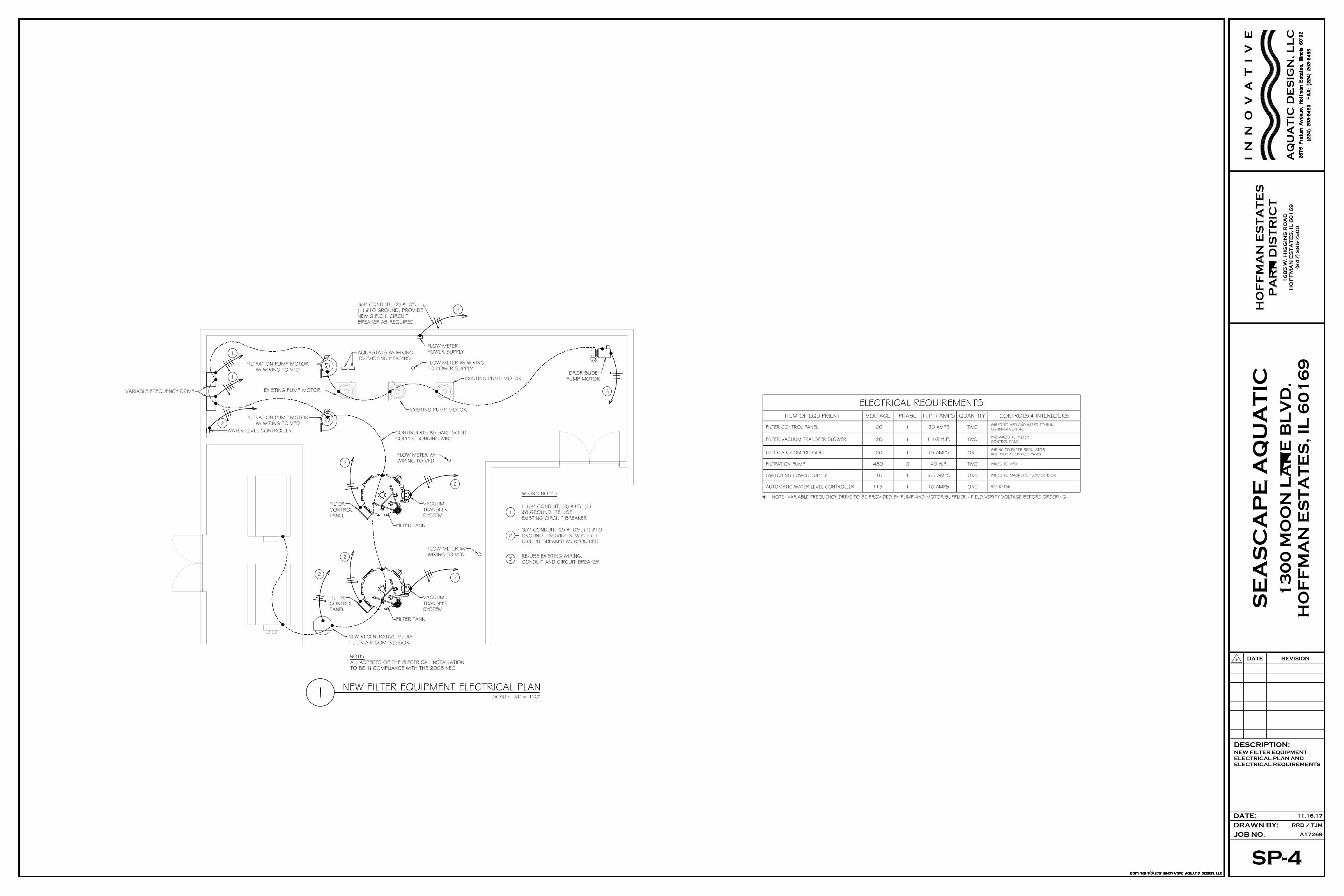
NEW FILTER EQUIPMENT ELECTRICAL PLAN1 SCALE: 1/4" = 1'-0"
WATER LEVEL CONTROLLER
NEW REGENERATIVE MEDIAFILTER AIR COMPRESSOR
FILTERCONTROLPANEL
FILTERCONTROLPANEL
FLOW METER W/WIRING TO VFD
FLOW METER W/ WIRINGTO POWER SUPPLY
FLOW METERPOWER SUPPLY
FLOW METER W/WIRING TO VFD
DROP SLIDEPUMP MOTOR
VACUUMTRANSFERSYSTEM
VACUUMTRANSFERSYSTEM
AQUASTATS W/ WIRINGTO EXISTING HEATERS
FILTRATION PUMP MOTORW/ WIRING TO VFD
FILTRATION PUMP MOTORW/ WIRING TO VFD
EXISTING PUMP MOTOR
EXISTING PUMP MOTOR
EXISTING PUMP MOTOR
FILTER TANK
FILTER TANK
3/4" CONDUIT, (2) #10'S,(1) #10 GROUND, PROVIDENEW G.F.C.I. CIRCUITBREAKER AS REQUIRED
3/4" CONDUIT, (2) #10'S, (1) #10GROUND, PROVIDE NEW G.F.C.I.CIRCUIT BREAKER AS REQUIRED
11 1/4" CONDUIT, (3) #4'S, (1)#8 GROUND, RE-USEEXISTING CIRCUIT BREAKER
2
1
2
2
2
2
2
2
2
3
RE-USE EXISTING WIRING,CONDUIT AND CIRCUIT BREAKER3
WIRING NOTES
WIRED TO VFDTWO40 H.P.3480FILTRATION PUMP
CONTROLS & INTERLOCKSH.P. / AMPSVOLTAGE PHASEITEM OF EQUIPMENT
ELECTRICAL REQUIREMENTSQUANTITY
FILTER CONTROL PANEL 1 TWO WIRED TO VFD AND WIRED TO RUNCONFIRM CONTACT30 AMPS120
FILTER VACUUM TRANSFER BLOWER PRE-WIRED TO FILTERCONTROL PANELTWO1 1/2 H.P.1120
120 15 AMPSWIRING TO FILTER REGULATORAND FILTER CONTROL PANELONE1FILTER AIR COMPRESSOR
* NOTE: VARIABLE FREQUENCY DRIVE TO BE PROVIDED BY PUMP AND MOTOR SUPPLIER - FIELD VERIFY VOLTAGE BEFORE ORDERING
115 1 10 AMPS ONEAUTOMATIC WATER LEVEL CONTROLLER SEE DETAIL
110 1 2.5 AMPS ONESWITCHING POWER SUPPLY WIRED TO MAGNETIC FLOW SENSOR
SP-5
ALTERNATE
CHEMICAL SYSTEM
LAYOUTS, EQUIPMENT LIST,
DATA, PLUMBING NOTES,
AND ELECTRICAL
REQUIREMENTS
JOB NO.
RRD / TJMDRAWN BY:
A17269
#
DATE: 11.16.17
REVISIONDATE
DESCRIPTION:
HO
FF
MA
N E
ST
AT
ES
PA
RK
DIS
TR
IC
T
13
00
MO
ON
LA
KE
BL
VD
.
HO
FF
MA
N E
ST
AT
ES
, I
L 6
01
69
SE
AS
CA
PE
AQ
UA
TIC
I N
N
O
V
A
T
I V
E
AQ
UA
TIC
DE
SIG
N, L
LC
16
85
W. H
IG
GIN
S R
OA
D
HO
FF
MA
N E
ST
AT
ES
, I
L 6
01
69
(8
47
) 8
85
-75
00
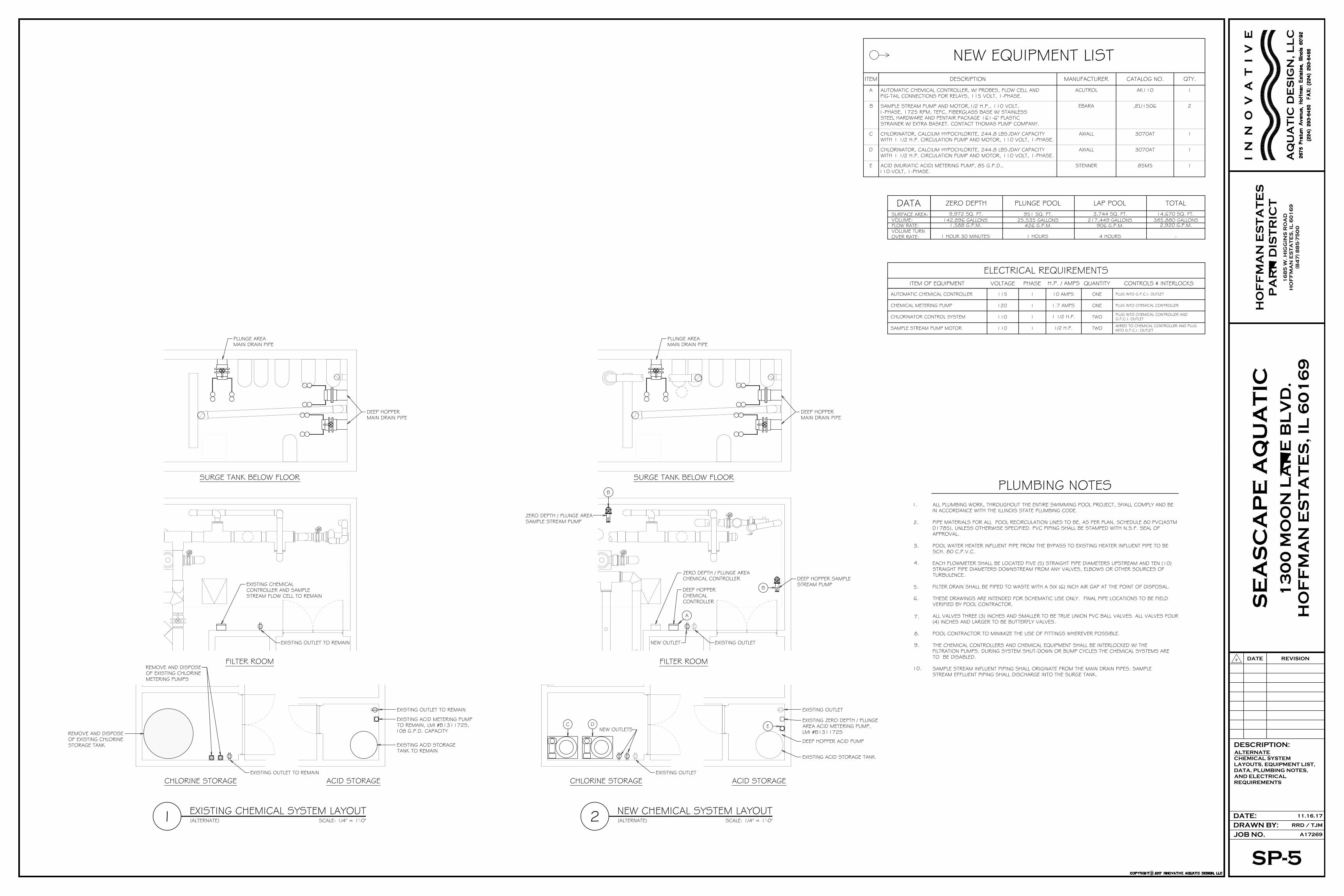
CATALOG NO. QTY.ITEM DESCRIPTION MANUFACTURER
NEW EQUIPMENT LIST
AUTOMATIC CHEMICAL CONTROLLER, W/ PROBES, FLOW CELL ANDPIG-TAIL CONNECTIONS FOR RELAYS, 115 VOLT, 1-PHASE.
A ACUTROL AK110 1
SAMPLE STREAM PUMP AND MOTOR,1/2 H.P., 110 VOLT,1-PHASE, 1725 RPM, TEFC, FIBERGLASS BASE W/ STAINLESSSTEEL HARDWARE AND PENTAIR PACKAGE 161-6" PLASTICSTRAINER W/ EXTRA BASKET. CONTACT THOMAS PUMP COMPANY.
B JEU1506 2EBARA
AXIALLC 3070AT 1
CHLORINATOR, CALCIUM HYPOCHLORITE, 244.8 LBS./DAY CAPACITYWITH 1 1/2 H.P. CIRCULATION PUMP AND MOTOR, 110 VOLT, 1-PHASE.
D
CHLORINATOR, CALCIUM HYPOCHLORITE, 244.8 LBS./DAY CAPACITYWITH 1 1/2 H.P. CIRCULATION PUMP AND MOTOR, 110 VOLT, 1-PHASE.
STENNERE 85M5 1
AXIALL 3070AT 1
ACID (MURIATIC ACID) METERING PUMP, 85 G.P.D.,110-VOLT, 1-PHASE.
EXISTING CHEMICAL SYSTEM LAYOUT1 SCALE: 1/4" = 1'-0"
SURGE TANK BELOW FLOOR
REMOVE AND DISPOSEOF EXISTING CHLORINESTORAGE TANK
REMOVE AND DISPOSEOF EXISTING CHLORINEMETERING PUMPS
EXISTING ACID METERING PUMPTO REMAIN, LMI #B131172S,108 G.P.D. CAPACITY
EXISTING ACID STORAGETANK TO REMAIN
EXISTING CHEMICALCONTROLLER AND SAMPLESTREAM FLOW CELL TO REMAIN
FILTER ROOM
ACID STORAGECHLORINE STORAGE
DEEP HOPPERMAIN DRAIN PIPE
PLUNGE AREAMAIN DRAIN PIPE
EXISTING OUTLET TO REMAIN
EXISTING OUTLET TO REMAIN
EXISTING OUTLET TO REMAIN
(ALTERNATE)
NEW CHEMICAL SYSTEM LAYOUT2 SCALE: 1/4" = 1'-0"
EXISTING ZERO DEPTH / PLUNGEAREA ACID METERING PUMP,LMI #B131172S
EXISTING ACID STORAGE TANK
ZERO DEPTH / PLUNGE AREACHEMICAL CONTROLLER DEEP HOPPER SAMPLE
STREAM PUMPB
B
A
C D E
PLUNGE AREAMAIN DRAIN PIPE
DEEP HOPPERMAIN DRAIN PIPE
SURGE TANK BELOW FLOOR
FILTER ROOM
ACID STORAGECHLORINE STORAGE
(ALTERNATE)
EXISTING OUTLET
NEW OUTLETS
EXISTING OUTLET
EXISTING OUTLETNEW OUTLET
ZERO DEPTH / PLUNGE AREASAMPLE STREAM PUMP
DEEP HOPPERCHEMICALCONTROLLER
DEEP HOPPER ACID PUMP
DATASURFACE AREA:VOLUME:FLOW RATE:VOLUME TURN OVER RATE:
951 SQ. FT.25,535 GALLONS
426 G.P.M.
1 HOURS
PLUNGE POOL3,744 SQ. FT.
217,449 GALLONS906 G.P.M.
4 HOURS
LAP POOL14,670 SQ. FT.
385,880 GALLONS2,920 G.P.M.
-
TOTAL9,972 SQ. FT.
142,896 GALLONS1,588 G.P.M.
1 HOUR 30 MINUTES
ZERO DEPTH
CONTROLS & INTERLOCKSH.P. / AMPSVOLTAGE PHASEITEM OF EQUIPMENT
ELECTRICAL REQUIREMENTSQUANTITY
115 1 10 AMPS ONEAUTOMATIC CHEMICAL CONTROLLER PLUG INTO G.F.C.I. OUTLET
PLUG INTO CHEMICAL CONTROLLERCHEMICAL METERING PUMP ONE1.7 AMPS1120
PLUG INTO CHEMICAL CONTROLLER ANDG.F.C.I. OUTLETCHLORINATOR CONTROL SYSTEM TWO1 1/2 H.P.1110
110 1 1/2 H.P. TWOSAMPLE STREAM PUMP MOTOR WIRED TO CHEMICAL CONTROLLER AND PLUGINTO G.F.C.I. OUTLET
PLUMBING NOTESALL PLUMBING WORK, THROUGHOUT THE ENTIRE SWIMMING POOL PROJECT, SHALL COMPLY AND BEIN ACCORDANCE WITH THE ILLINOIS STATE PLUMBING CODE.
PIPE MATERIALS FOR ALL POOL RECIRCULATION LINES TO BE, AS PER PLAN, SCHEDULE 80 PVC(ASTMD1785), UNLESS OTHERWISE SPECIFIED. PVC PIPING SHALL BE STAMPED WITH N.S.F. SEAL OFAPPROVAL.
POOL WATER HEATER INFLUENT PIPE FROM THE BYPASS TO EXISTING HEATER INFLUENT PIPE TO BESCH. 80 C.P.V.C.
EACH FLOWMETER SHALL BE LOCATED FIVE (5) STRAIGHT PIPE DIAMETERS UPSTREAM AND TEN (10)STRAIGHT PIPE DIAMETERS DOWNSTREAM FROM ANY VALVES, ELBOWS OR OTHER SOURCES OFTURBULENCE.
FILTER DRAIN SHALL BE PIPED TO WASTE WITH A SIX (6) INCH AIR GAP AT THE POINT OF DISPOSAL.
THESE DRAWINGS ARE INTENDED FOR SCHEMATIC USE ONLY. FINAL PIPE LOCATIONS TO BE FIELDVERIFIED BY POOL CONTRACTOR.
ALL VALVES THREE (3) INCHES AND SMALLER TO BE TRUE UNION PVC BALL VALVES. ALL VALVES FOUR(4) INCHES AND LARGER TO BE BUTTERFLY VALVES.
1.
2.
3.
4.
5.
6.
7.
10.
9.
8. POOL CONTRACTOR TO MINIMIZE THE USE OF FITTINGS WHEREVER POSSIBLE.
THE CHEMICAL CONTROLLERS AND CHEMICAL EQUIPMENT SHALL BE INTERLOCKED W/ THEFILTRATION PUMPS. DURING SYSTEM SHUT-DOWN OR BUMP CYCLES THE CHEMICAL SYSTEMS ARETO BE DISABLED.
SAMPLE STREAM INFLUENT PIPING SHALL ORIGINATE FROM THE MAIN DRAIN PIPES. SAMPLESTREAM EFFLUENT PIPING SHALL DISCHARGE INTO THE SURGE TANK.
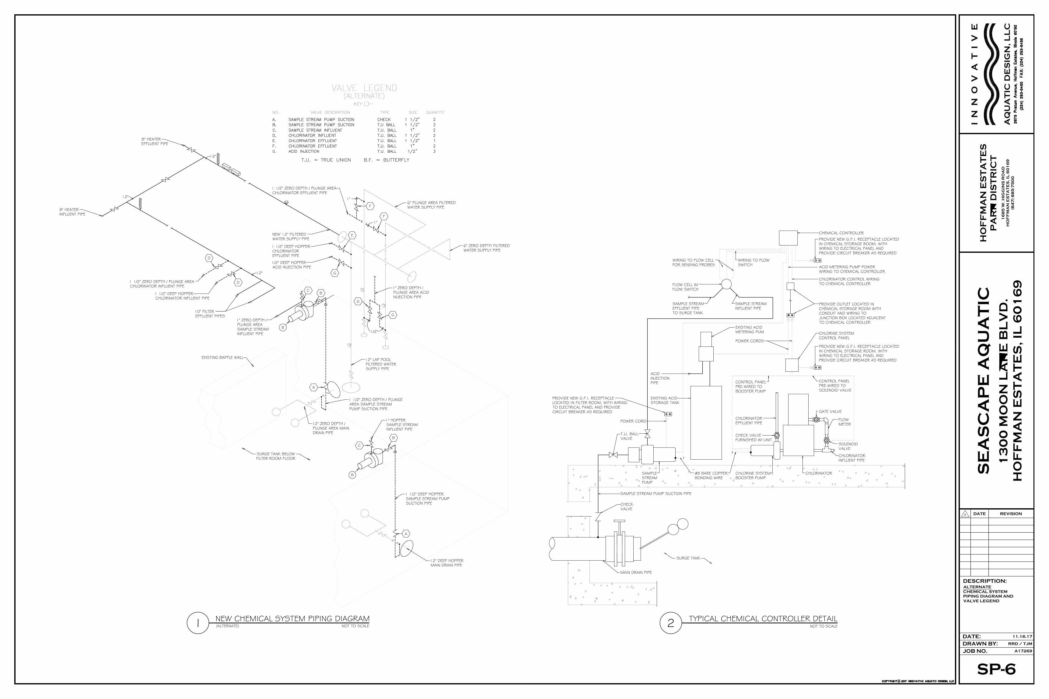
SP-6
ALTERNATE
CHEMICAL SYSTEM
PIPING DIAGRAM AND
VALVE LEGEND
JOB NO.
RRD / TJMDRAWN BY:
A17269
#
DATE: 11.16.17
REVISIONDATE
DESCRIPTION:
HO
FF
MA
N E
ST
AT
ES
PA
RK
DIS
TR
IC
T
13
00
MO
ON
LA
KE
BL
VD
.
HO
FF
MA
N E
ST
AT
ES
, I
L 6
01
69
SE
AS
CA
PE
AQ
UA
TIC
I N
N
O
V
A
T
I V
E
AQ
UA
TIC
DE
SIG
N, L
LC
16
85
W. H
IG
GIN
S R
OA
D
HO
FF
MA
N E
ST
AT
ES
, I
L 6
01
69
(8
47
) 8
85
-75
00
TYPICAL CHEMICAL CONTROLLER DETAIL2 NOT TO SCALE
SAMPLE STREAMINFLUENT PIPE
#8 BARE COPPERBONDING WIRE
EXISTING ACIDSTORAGE TANK
SAMPLE STREAMEFFLUENT PIPETO SURGE TANK
WIRING TO FLOWSWITCH
CHLORINATOREFFLUENT PIPE
CHECK VALVEFURNISHED W/ UNIT
CONTROL PANELPRE-WIRED TOSOLENOID VALVE
SOLENOIDVALVE
FLOWMETER
GATE VALVE
CHLORINATORINFLUENT PIPE
CONTROL PANELPRE-WIRED TOBOOSTER PUMP
CHLORINE SYSTEMBOOSTER PUMP
CHLORINE SYSTEMCONTROL PANEL
CHEMICAL CONTROLLER
EXISTING ACIDMETERING PUM
FLOW CELL W/FLOW SWITCH
PROVIDE NEW G.F.I. RECEPTACLE LOCATEDIN CHEMICAL STORAGE ROOM, WITHWIRING TO ELECTRICAL PANEL ANDPROVIDE CIRCUIT BREAKER AS REQUIRED
WIRING TO FLOW CELLFOR SENSING PROBES
PROVIDE OUTLET LOCATED INCHEMICAL STORAGE ROOM WITHCONDUIT AND WIRING TOJUNCTION BOX LOCATED ADJACENTTO CHEMICAL CONTROLLER
POWER CORDS
CHLORINATOR CONTROL WIRINGTO CHEMICAL CONTROLLER
ACID METERING PUMP POWERWIRING TO CHEMICAL CONTROLLER
PROVIDE NEW G.F.I. RECEPTACLE LOCATEDIN CHEMICAL STORAGE ROOM, WITHWIRING TO ELECTRICAL PANEL ANDPROVIDE CIRCUIT BREAKER AS REQUIRED
CHLORINATOR
ACIDINJECTIONPIPE
T.U. BALLVALVE
SAMPLESTREAMPUMP
POWER CORD
CHECKVALVE
MAIN DRAIN PIPE
PROVIDE NEW G.F.I. RECEPTACLELOCATED IN FILTER ROOM, WITH WIRINGTO ELECTRICAL PANEL AND PROVIDECIRCUIT BREAKER AS REQUIRED
SURGE TANK
SAMPLE STREAM PUMP SUCTION PIPE
12"
12"
12"
NEW CHEMICAL SYSTEM PIPING DIAGRAM1 NOT TO SCALE
EXISTING BAFFLE WALL
NEW 12" FILTEREDWATER SUPPLY PIPE
8" HEATEREFFLUENT PIPE
8" HEATERINFLUENT PIPE
1 1/2" ZERO DEPTH / PLUNGE AREACHLORINATOR INFLUENT PIPE
1 1/2" DEEP HOPPERCHLORINATOR INFLUENT PIPE
10" FILTEREFFLUENT PIPES
1 1/2" DEEP HOPPERCHLORINATOREFFLUENT PIPE
1/2" DEEP HOPPERACID INJECTION PIPE
F
F
G
G
BC
1" ZERO DEPTH /PLUNGE AREA ACIDINJECTION PIPE
1/2"
6" ZERO DEPTH FILTEREDWATER SUPPLY PIPE
1"
1"
1 1/2" ZERO DEPTH / PLUNGE AREACHLORINATOR EFFLUENT PIPE
6" PLUNGE AREA FILTEREDWATER SUPPLY PIPE
E
G
1" ZERO DEPTH /PLUNGE AREASAMPLE STREAMINFLUENT PIPE
B
D
D
(ALTERNATE)
12" LAP POOLFILTERED WATERSUPPLY PIPE
12" ZERO DEPTH /PLUNGE AREA MAINDRAIN PIPE
A
1 1/2" ZERO DEPTH / PLUNGEAREA SAMPLE STREAMPUMP SUCTION PIPE
C
B
B
1" HOPPERSAMPLE STREAMINFLUENT PIPE
A
1 1/2" DEEP HOPPERSAMPLE STREAM PUMPSUCTION PIPE
12" DEEP HOPPERMAIN DRAIN PIPE