part 1 - microsoft · 34 gears january/february 2008 a look at the gm 6l80; part 1 the first of ten...
TRANSCRIPT
34 GEARSJanuary/February2008
A Look at the GM 6L80; Part 1
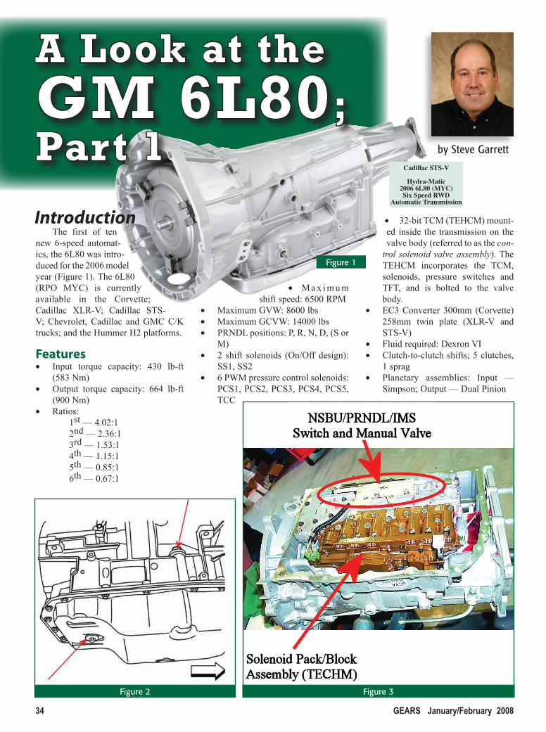
The first of ten new 6-speed automat-ics, the 6L80 was intro-duced for the 2006 model year (Figure 1). The 6L80 (RPO MYC) is currently available in the Corvette; Cadillac XLR-V; Cadillac STS-V; Chevrolet, Cadillac and GMC C/K trucks; and the Hummer H2 platforms.
Features• Input torque capacity: 430 lb-ft
(583 Nm)• Output torque capacity: 664 lb-ft
(900 Nm)• Ratios:
1st — 4.02:12nd — 2.36:13rd — 1.53:14th — 1.15:15th — 0.85:16th — 0.67:1
• M a x i m u m shift speed: 6500 RPM
• Maximum GVW: 8600 lbs• Maximum GCVW: 14000 lbs• PRNDL positions: P, R, N, D, (S or
M)• 2 shift solenoids (On/Off design):
SS1, SS2• 6 PWM pressure control solenoids:
PCS1, PCS2, PCS3, PCS4, PCS5, TCC
• 32-bit TCM (TEHCM) mount-ed inside the transmission on the valve body (referred to as the con-
trol solenoid valve assembly). The TEHCM incorporates the TCM, solenoids, pressure switches and TFT, and is bolted to the valve body.
• EC3 Converter 300mm (Corvette) 258mm twin plate (XLR-V and STS-V)
• Fluid required: Dexron VI• Clutch-to-clutch shifts; 5 clutches,
1 sprag• Planetary assemblies: Input —
Simpson; Output — Dual Pinion
by Steve Garrett
Introduction
Cadillac STS-V
Hydra-Matic2006 6L80 (MYC)Six Speed RWD
Automatic Transmission
Figure 1
Figure 2 Figure 3
A Look at the GM 6L80; Part 1
QUALITY TRANSMISSION SOLENOIDSFROM THE GLOBAL LEADER IN AUTOMATIC
TRANSMISSION SYSTEMS TECHNOLOGY.
BorgWarner Inc. Transmission Systems
1350 North Greenbriar Drive Unit B Addison, IL 60101 (630) 261-9980www.borgwarner.com
The BorgWarner Indianapolis 500 Trophy is a registered trademark of BorgWarner Inc.
Precision matters. Precision matters.
oday's complex electronic transmissions require precise and accuratecontrol, like the control provided by BorgWarner quality transmissionsolenoids. Our solenoids are engineered to exacting specifications,improving fuel economy and reducing emissions.
Make BorgWarner your one-stop source for automatic transmissioncontrols that are competitively priced, readily available and guaranteedto fit your rebuilds. Call your authorized distributor today and askfor the original parts from the leader in automatic transmissiontechnology...BorgWarner Inc.
TTM
borgwarnerplcd.indd 25borgwarnerplcd.indd 25 4/11/06 3:26:05 PM4/11/06 3:26:05 PM

36 GEARSJanuary/February2008
A Look at the GM 6L80; Part 1
• Vane-style oil pump• Internally-mounted input and output shaft, and Hall
Effect speed sensors• Internal Mode Switch (IMS)• Performance Algorithm Shifting (PAS) program-
ming• Performance Algorithm Lift foot (PAL) program-
ming • Sport mode and TAP shift• Adaptive strategies with fast learn capabilities• Up to 75 transmission-only DTCs
Checking Fluid LevelThe 6L80 transmission requires an unusual process
for checking its fluid level. Many 6L80 applications don’t have a dipstick; there’s a plug in the dipstick hole. The plug can be removed and the hole used as a fill point for transmission fluid (Figure 2). Here’s how to check the
Figure 4
fluid level:Bring the transmission fluid temperature between 86º–
122ºF (30º–50ºC). You can verify this using a scan tool, the driver information center, or the transmission gauge.
If the transmission has a dipstick, use that to check the fluid level; on applications without a dipstick: • Park the vehicle on level ground.• Start the engine and let it idle.• Shift the transmission through each range, pausing in each
range for about 3 seconds to give the clutches a chance to fill.
• Place the transmission in park.• Remove the level control plug located in the transmission
oil pan. The fluid should drip out the level control hole. If so, the fluid level is okay.ØIf fluid doesn’t drip from the level control hole,
add Dexron VI until fluid starts to drip from the hole.
ØIf fluid runs from the hole, wait until the fluid stops running out to lower the fluid to the proper level.
The level is correct when fluid drips from the hole. If a steady stream is present or no flow is present the
Figure 5
Figure 6
GoldStripe is a registered trademark of SPX Filtran, Raybestos and Allomatic are registered trademarks of Raybestos Powertrain Corporation.
38 GEARSJanuary/February2008
A Look at the GM 6L80; Part 1
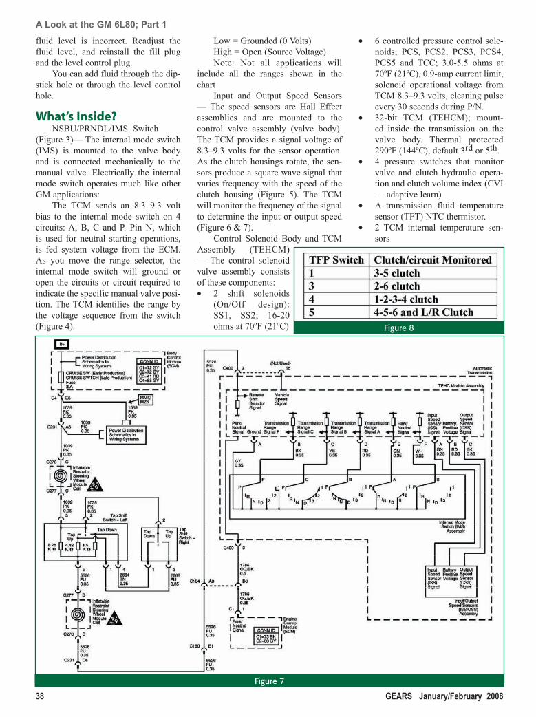
fluid level is incorrect. Readjust the fluid level, and reinstall the fill plug and the level control plug.
You can add fluid through the dip-stick hole or through the level control hole.
What’s Inside?NSBU/PRNDL/IMS Switch
(Figure 3)— The internal mode switch (IMS) is mounted to the valve body and is connected mechanically to the manual valve. Electrically the internal mode switch operates much like other GM applications:
The TCM sends an 8.3–9.3 volt bias to the internal mode switch on 4 circuits: A, B, C and P. Pin N, which is used for neutral starting operations, is fed system voltage from the ECM. As you move the range selector, the internal mode switch will ground or open the circuits or circuit required to indicate the specific manual valve posi-tion. The TCM identifies the range by the voltage sequence from the switch (Figure 4).
Low = Grounded (0 Volts)High = Open (Source Voltage) Note: Not all applications will
include all the ranges shown in the chart
Input and Output Speed Sensors — The speed sensors are Hall Effect assemblies and are mounted to the control valve assembly (valve body). The TCM provides a signal voltage of 8.3–9.3 volts for the sensor operation. As the clutch housings rotate, the sen-sors produce a square wave signal that varies frequency with the speed of the clutch housing (Figure 5). The TCM will monitor the frequency of the signal to determine the input or output speed (Figure 6 & 7).
Control Solenoid Body and TCM Assembly (TEHCM) — The control solenoid valve assembly consists of these components:• 2 shift solenoids
(On/Off design): SS1, SS2; 16-20 ohms at 70ºF (21ºC)
• 6 controlled pressure control sole-noids; PCS, PCS2, PCS3, PCS4, PCS5 and TCC; 3.0-5.5 ohms at 70ºF (21ºC), 0.9-amp current limit, solenoid operational voltage from TCM 8.3–9.3 volts, cleaning pulse every 30 seconds during P/N.
• 32-bit TCM (TEHCM); mount-ed inside the transmission on the valve body. Thermal protected 290ºF (144ºC), default 3rd or 5th.
• 4 pressure switches that monitor valve and clutch hydraulic opera-tion and clutch volume index (CVI — adaptive learn)
• A transmission fluid temperature sensor (TFT) NTC thermistor.
• 2 TCM internal temperature sen-sors
Figure 8
Figure 7
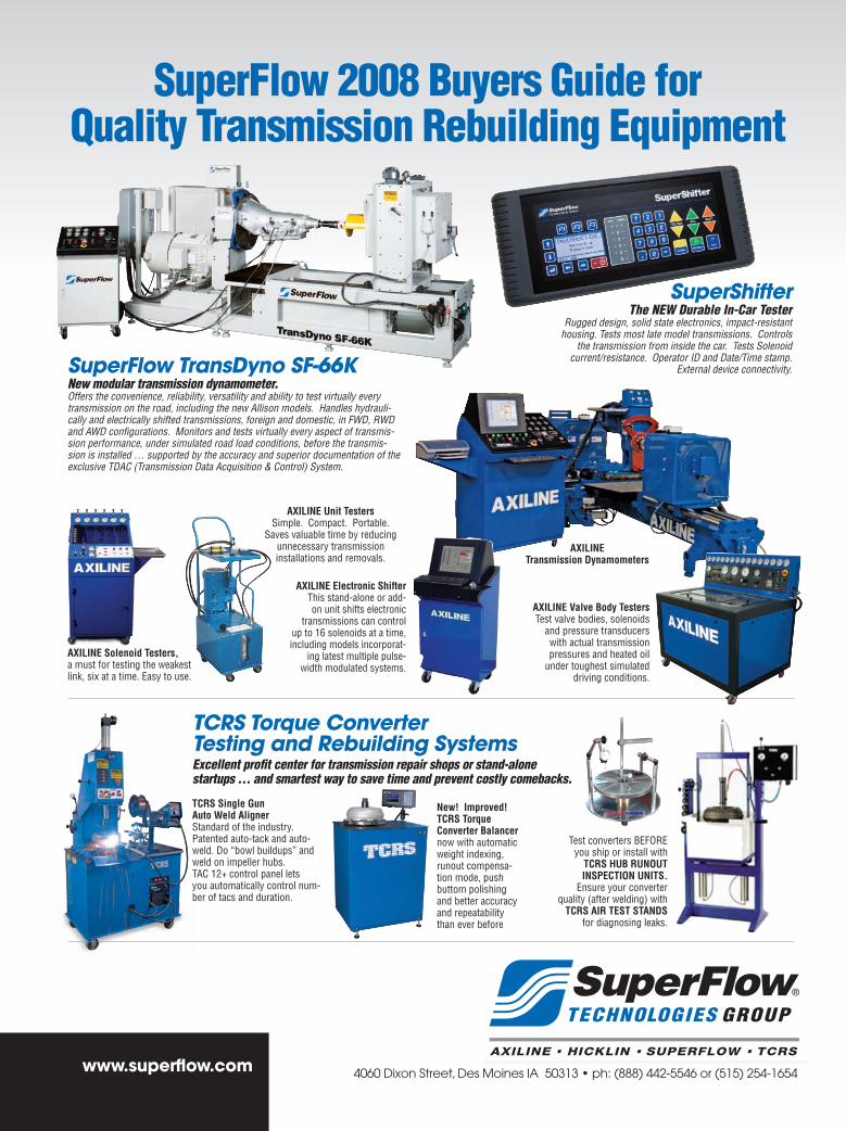
Test converters BEFORE you ship or install with
TCRS Hub RuNOuTINSpeCTION uNITS.
Ensure your converter quality (after welding) with
TCRS AIR TeST STANDS for diagnosing leaks.
AXILINe unit TestersSimple. Compact. Portable.
Saves valuable time by reducing unnecessary transmission installations and removals.
AXILINe Valve body TestersTest valve bodies, solenoids
and pressure transducers with actual transmission pressures and heated oil
under toughest simulated driving conditions.
AXILINe electronic ShifterThis stand-alone or add-on unit shifts electronic
transmissions can control up to 16 solenoids at a time, including models incorporat-
ing latest multiple pulse-width modulated systems.
New! Improved!TCRS Torque Converter balancernow with automatic weight indexing,runout compensa-tion mode, push buttom polishing and better accuracy and repeatability than ever before
TCRS Torque Converter Testing and Rebuilding Systems Excellent profit center for transmission repair shops or stand-alone startups … and smartest way to save time and prevent costly comebacks.
AXILINe Solenoid Testers, a must for testing the weakest link, six at a time. Easy to use.
SuperFlow 2008 Buyers Guide forQuality Transmission Rebuilding Equipment
SuperShifter The NEW Durable In-Car Tester
Rugged design, solid state electronics, impact-resistant housing. Tests most late model transmissions. Controls
the transmission from inside the car. Tests Solenoid current/resistance. Operator ID and Date/Time stamp.
External device connectivity.SuperFlow TransDyno SF-66KNew modular transmission dynamometer. Offers the convenience, reliability, versatility and ability to test virtually every transmission on the road, including the new Allison models. Handles hydrauli-cally and electrically shifted transmissions, foreign and domestic, in FWD, RWD and AWD configurations. Monitors and tests virtually every aspect of transmis-sion performance, under simulated road load conditions, before the transmis-sion is installed … supported by the accuracy and superior documentation of the exclusive TDAC (Transmission Data Acquisition & Control) System.
AXILINeTransmission Dynamometers
ureally need
w…
www.superflow.com
TCRS Single Gun Auto Weld AlignerStandard of the industry. Patented auto-tack and auto-weld. Do “bowl buildups” and weld on impeller hubs.TAC 12+ control panel lets you automatically control num-ber of tacs and duration.
Gears.Fullpg4colorAd.12.13.indd 1 12/19/07 5:11:03 PM

40 GEARSJanuary/February2008
A Look at the GM 6L80; Part 1
Pressure Switches — The pres-sure switches are housed as part of the control solenoid valve assembly. 4 switches are used: 1, 3, 4 and 5. The switches provide an input to the TCM and have two basic functions:• To monitor clutch regulator valve
and clutch hydraulic operation (Figure 8).
• To monitor clutch volume index (CVI — adaptive learning).
Solenoid OperationIMPORTANT: In systems using
the Bosch solenoid system, ON/OFF refers to the solenoids’ hydraulic com-manded position, not their electrical command as with other applications; more on this later.
Shift solenoid and PCS operation is controlled by the TEHCM (TCM). The TCM regulates the feed voltage to the solenoids between 8.3–9.3 volts (Figure 9). The TCM then regulates the current flow through the solenoids. The shift solenoids are On/Off design with the TCM controlling the power and ground for the solenoids (Figure 10). The pressure control solenoids are high-side, PWM controlled. The TCM is overcurrent and overtemperature pro-tected (Figure 11, 12, &13).
Bosch refers to the solenoids by their hydraulic operation: Normally High (NH) or Normally Low (NL). Normally High means the solenoid allows pressure to travel to the clutch when the solenoid is off. Normally Low means the solenoid prevents pres-sure from getting to a clutch when the solenoid is off.
IMPORTANT: This concept of Normally High and Normally Low to describe solenoid operation is far more involved — and confusing — than it might initially appear. We’ll discuss the operation of the Bosch solenoids in detail in an upcoming issue of GEARS.
The solenoids are protected by the filter plate. The filter plate is housed between the valve body and the con-trol solenoid valve assembly (TEHCM) and must be replaced any time the valve body or control solenoid valve assembly (TEHCM) is replaced, or are unbolted from each other.
ClutchesThe 6L80 transmission (Figure 14)
uses three rotating clutches and two stationary clutches.
1-2-3-4/Forward Clutch — This clutch is applied in 1st through 4th gears. The 1-2-3-4/forward clutch is located in the bottom of the reverse clutch housing. When applied, it locks the reverse drum to the 2-6 and 3-5-reverse shell to drive the lower sun gear for the output carrier.
2-6 Clutch — This is one of the stationary clutches. It’s located on top of the center support assembly. It pre-vents the 2-6 and 3-5-reverse shell from rotating.
3-5-Reverse Clutch — This clutch is used in 3rd, 5th and reverse. It’s located in the reverse clutch housing. When applied, it connects the reverse drum to the 2-6 and 3-5-reverse shell. The clutch then drives the front output sun gear in the output carrier.
4-5-6/Input Clutch — This clutch is located in the input housing. When applied, it locks the input housing to the 4-5-6 drive hub, which drives the lower output carrier.
Low/Reverse Clutch — This sta-
tionary clutch is located in the lower section of the center support. The Low/Reverse clutch is used in reverse and manual low.
Figure 11
Figure 9
Figure 10

42 GEARSJanuary/February2008
A Look at the GM 6L80; Part 1
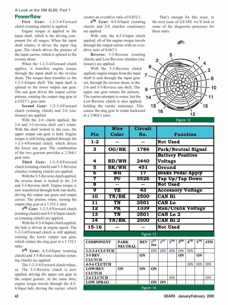
PowerflowFirst Gear: 1-2-3-4/Forward
clutch (rotating clutch) is applied.Engine torque is applied to the
input shaft, which is the driving com-ponent for all ranges. When the input shaft rotates, it drives the input ring gear. The clutch drives the pinions of the input carrier, which is splined to the reverse drum.
When the 1-2-3-4/Forward clutch applies, it transfers engine torque through the input shaft to the reverse drum. The torque then transfers to the 1-2-3-4/input shell. The input shell is splined to the lower output sun gear. The sun gear drives the output carrier pinions, rotating the output ring gear at a 4.027:1 gear ratio.
Second Gear: 1-2-3-4/Forward clutch (rotating clutch) and 2-6 (sta-tionary) are applied.
With the 2-6 clutch applied, the 2-6 and 3-5-reverse shell can’t rotate. With the shell locked to the case, the upper output sun gear is held. Engine torque is still being applied through the 1-2-3-4/Forward clutch, which drives the lower sun gear. The combination of the two gearsets provides a 2.364:1 gear ratio.
Third Gear: 1-2-3-4/Forward clutch (rotating clutch) and 3-5-Reverse clutches (rotating clutch) are applied.
With the 3-5-Reverse clutch applied, the reverse drum is locked to the 2-6 and 3-5-Reverse shell. Engine torque is now transferred through both sun shells, driving the output sun gears and output carrier. The pinions rotate, turning the output ring gear at a 1.532:1 ratio.
4th Gear: 1-2-3-4/Forward clutch (rotating clutch) and 4-5-6/Input clutch-es (rotating clutch) are applied.
With the 4-5-6/Input clutch applied, the hub is driven at engine speed. The 1-2-3-4/Forward clutch is still applied, rotating the lower output sun gear, which rotates the ring gear at a 1.152:1 ratio.
5th Gear: 4-5-6/Input (rotating clutch) and 3-5-Reverse clutches (rotat-ing clutch) are applied.
The 1-2-3-4/Forward clutch releas-es. The 3-5-Reverse clutch is now applied, driving the upper sun gear in the output gearset. At the same time, engine torque travels through the 4-5-6/Input hub, driving the carrier, which
creates an overdrive ratio of 0.852:1.6th Gear: 4-5-6/Input (rotating
clutch) and 2-6 clutches (stationary) are applied.
With only the 4-5-6/input clutch applied, all of the engine torque travels through the output carrier with an over-drive ratio of 0.667:1.
Reverse: 3-5-Reverse (rotating clutch) and Low/Reverse clutches (sta-tionary) are applied.
With the 3-5-Reverse clutch applied, engine torque from the input shaft is sent through the input gear set, through the reverse drum, to the 2-6 and 3-5-Reverse sun shell. The upper sun gear rotates the pinions. The carrier attempts to rotate, but the Low/Reverse clutch is also applied, holding the carrier stationary. This causes the ring gear to rotate backward at a 3.064:1 ratio.
That’s enough for this issue; in the next issue of GEARS, we’ll look at some of the diagnostic processes for these units.
Figure 12
Figure 13
Figure 14
TRAFFIC PROOF-READER
PRODUCTION COPYWRITER DESIGNER ART DIR. CREATIVE DIR.
PRODUCTINSIGHT/CLAIMS
PRODUCTACCURACY
LEGAL ACCOUNT CLIENT SPELL CHECK
JOB#: GIMX07M0143-Engine Ad.indd CLIENT: GMSPO Powertrain DESC: Engine Ad CLOSE DATE: 5/21/07
PUB DATE: NA PUBLICATION: Gears COLORS/SPECS: pg 4/c bl SCALE: 100%
GUTTER: None BLEED: 8.375 in x 11.125 in TRIM: 7.75 in x 10.5 in SAFETY: 6.875 in x 9.75 in
ACCOUNT: Stephanie Miller ART DIRECTOR: Matt Balcer COPYWRITER: George KatsarelasROUTER #: 3PRINT PROD: Kathy Dawson TRAFFIC: Linda Rosbury STUDIO ARTIST: Kangas
DOC PATH: Studio:Volumes:Studio:Documents:SPO:Powertrain:2007:GIMX07M0143-Engine Ad.indd REV DATE: 12-7-2007 4:32 PMNOTES: Art is lo-res. To be produced through Schawk.IMAGES: 07GAPT00003_LR_RGB.tif (CMYK; 77%), Genuine_GMParts_Pos_Gray_CMYK.ai (45%), Genuine_GMParts_Neg_Wht_CMYK_no®.ai (37.11%)
COLORS:
FONTS: Goodwrench Klavika (Bold, Regular, Medium; OpenType)
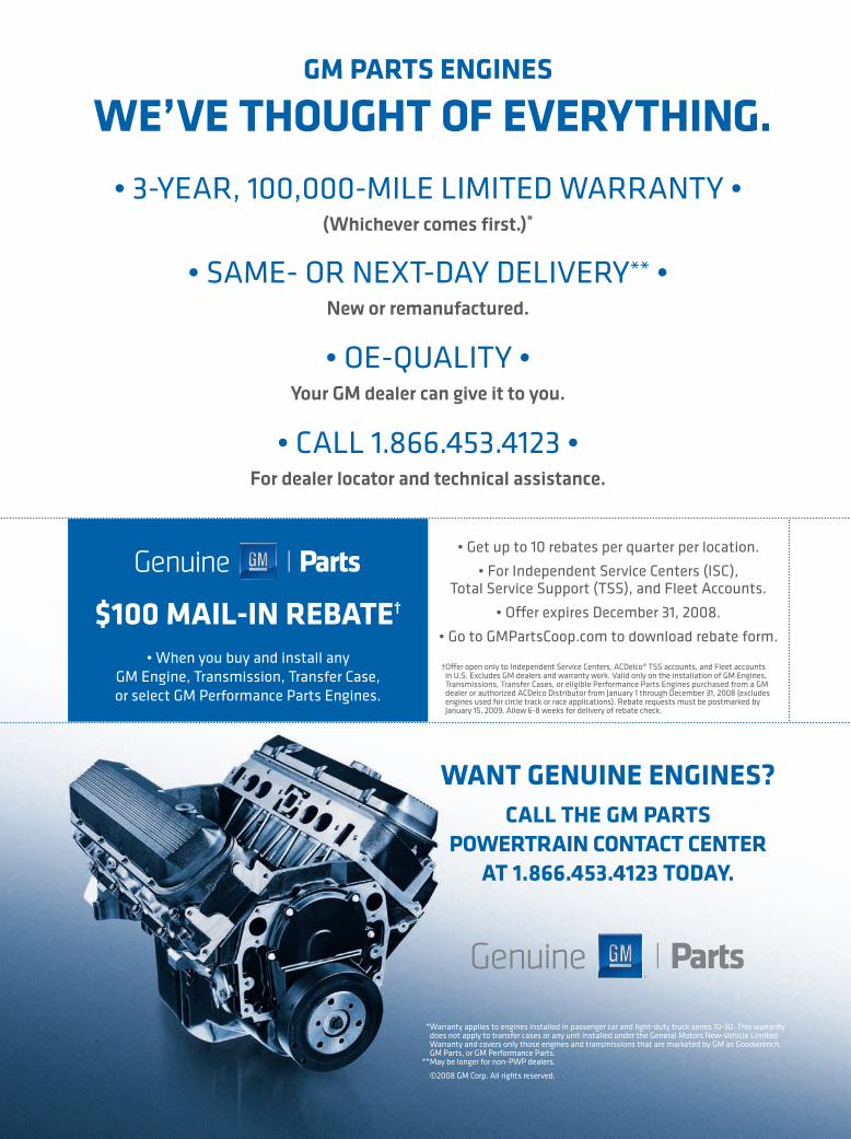
Want Genuine enGines?CaLL the GM parts
poWertrain ContaCt Center at 1.866.453.4123 today.
GM parts enGines
We’ve thouGht of everythinG.
*
**
$100 MaiL-in rebate†
119762A01
119762A01.indd 1 12/7/07 7:26:20 PM