part 1 : modelling · part 1 : modelling practical application of the mfe ... finite element model...
TRANSCRIPT

Institute of Structural Engineering Page 1
Method of Finite Elements I
Part 1 : Modelling
Practical application of the MFE
Method of Finite Elements I
Institute of Structural Engineering Page 2
Method of Finite Elements I
Goals of this Lecture
• Demonstrating the importance of modelling
when applying the MFE
• Closing the gap between
structural analysis theory and
application of FE software
Note: In this lecture the focus is on structural engineering

Institute of Structural Engineering Page 3
Method of Finite Elements I
Structural Engineering=
Mission impossible
"Structural engineering is the art of molding materials we
don't wholly understand, into shapes we can't fully analyze,
so as to withstand forces we can't really assess, in such a
way that the community at large has no reason to suspect
the extent of our ignorance."
Always keep this in mind when doing
advanced FE calculations!
Institute of Structural Engineering Page 4
Method of Finite Elements I
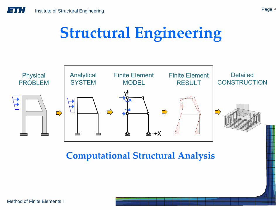
Structural Engineering
X
Y
Physical
PROBLEM
Analytical
SYSTEM
Finite Element
MODELFinite Element
RESULT
Detailed
CONSTRUCTION
Computational Structural Analysis

Institute of Structural Engineering Page 5
Method of Finite Elements I
X
Y
Physical
PROBLEM
Analytical
SYSTEM
Finite Element
MODELFinite Element
RESULT
Detailed
CONSTRUCTION
Modelling Calculation Detailing
engineer computer engineer
Note: The computer is playing a minor role!
Structural Engineering

Institute of Structural Engineering Page 6
Method of Finite Elements I
FE Modelling
X
Y
Physical
PROBLEM
Analytical
SYSTEM
Finite Element
MODEL
• Structure type e.g. 2D/3D, frame, shell
• Analysis type linear statics, nonlinear dynamics
• Analytical system nodes, elements, boundary conditions
• Actions moving load, earthquake
Modelling = defining…

Institute of Structural Engineering Page 7
Method of Finite Elements I
World
Object Airplane Building
Problem Vibrations
Cracking
Deformations
Collapse
(FE) Model
Analysis Linear dynamics
Stresses
Linear statics/dynamics
Ultimate load
Structure 3D shell 2.5D slabs
3D frame
Mechanical Eng Civil Eng
FE Modelling
Institute of Structural Engineering Page 8
Method of Finite Elements I
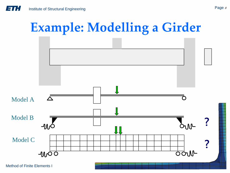
Example: Modelling a Girder
Model B
Model A
Model C
?
?

Institute of Structural Engineering Page 9
Method of Finite Elements I
Modelling
• Building an appropriate, consistent analytical system
• Making assumptions based on engineering judgement
• The (one and only) correct model does not exit
Modelling is hard, but the most important step!

Institute of Structural Engineering Page 10
Method of Finite Elements I
Example: Slab on ColumnsFE Model
2D slab
3 dof/node, bending element
linear elastic analysis
point support
=> Stress concentrations at support node !
Best FE model = ?
FE Model A
slab
column

Institute of Structural Engineering Page 11
Method of Finite Elements I
1. Find reactions from point support
FE Model B
Example: Slab on Columns
=> No clamped support possible !
FE Model C
elastic element support
=> Best results !
2. Add correcting loads:

Institute of Structural Engineering Page 12
Method of Finite Elements I
Example: Modelling a Building
Physical Problem FE Models
Incr
ease
d c
om
ple
xit
y
?
3D shell
3D frame
2.5D slabs + 3D frame /
system of beams
Institute of Structural Engineering Page 13
Method of Finite Elements I
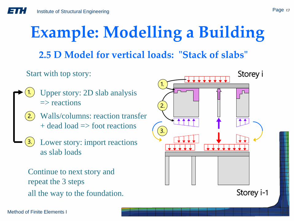
Example: Modelling a Building
1.
2.
Storey i
Storey i-1
3.
2.5 D Model for vertical loads: "Stack of slabs"
1. Upper story: 2D slab analysis
=> reactions
2. Walls/columns: reaction transfer
+ dead load => foot reactions
3. Lower story: import reactions
as slab loads
Start with top story:
Continue to next story and
repeat the 3 steps
all the way to the foundation.

Institute of Structural Engineering Page 14
Method of Finite Elements I
Example: Modelling a Building
3D frame /
system of beams3D shell
Equivalent
cantilever
beam
??
EarthquakeAnalysis

Institute of Structural Engineering Page 15
Method of Finite Elements I
Model: 3D Shell
• Good
– Suitable for any geometry (curved shells..)
– Nicest result pictures (marketing..)
• Bad
– Most detailed model (big input => big output)
– Verifying the results is extremely demanding
– Not fully covered by codes
– Long computing times (=> no sensitivity analysis possible..)
– No direct results for construction (reinforcement of walls..)
• Verdict
– Not suited for engineering practice

Institute of Structural Engineering Page 16
Method of Finite Elements I
Model: 3D Frame
• Good
– Based on beam theory (=> result interpretation..)
– Directly supported by codes
– Very well covered by literature
– Suitable for all types of analysis
– Short computing times (=> sensitivity analysis..)
– Direct results for construction
• Bad
– Cannot model 3D curved shell structures
• Verdict
– Best model for engineering practice
Institute of Structural Engineering Page 17
Method of Finite Elements I
The 4 Golden Rulesof FE-Modelling
1. Understand the problem before
starting the FE software
2. Model the (structural) system not the geometry
3. Unverifiable FE results are generally false
4. Follow the basic system assumptions
all the way to the construction

Institute of Structural Engineering Page 18
Method of Finite Elements I