part # 11267199 68-74 nova rear airbar - ridetech.com · 6 16. one helpful trick to help maintain...
TRANSCRIPT
350 S. St. Charles St. Jasper, In. 47546 Ph. 812.482.2932 Fax 812.634.6632
www.ridetech.com
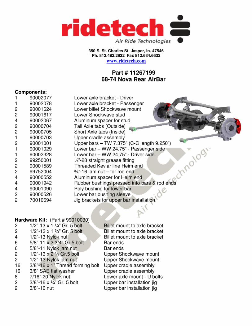
Part # 11267199 68-74 Nova Rear AirBar
Components: 1 90002077 Lower axle bracket - Driver 1 90002078 Lower axle bracket - Passenger 2 90001624 Lower billet Shockwave mount 2 90001617 Lower Shockwave stud 4 90002067 Aluminum spacer for stud 2 90000704 Tall Axle tabs (Outside) 2 90000705 Short Axle tabs (Inside) 1 90000703 Upper cradle assembly 2 90001001 Upper bars – TW 7.375” (C-C length 9.250”) 1 90001029 Lower bar – WW 24.75” - Passenger side 1 90002328 Lower bar – WW 24.75” - Driver side 2 99250001 ¼”-28 straight grease fitting 2 90001589 Threaded Kevlar line Heim end 2 99752004 ¾”-16 jam nut – for rod end 4 90000552 Aluminum spacer for Heim end 4 90001942 Rubber bushings pressed into bars & rod ends 4 90001090 Poly bushing for lower bar 2 90000526 Lower bar bushing sleeve 2 70010694 Jig brackets for upper bar installation
Hardware Kit: (Part # 99010030) 2 1/2”-13 x 1 ¼” Gr. 5 bolt Billet mount to axle bracket 2 1/2"-13 x 1 ¾” Gr. 5 bolt Billet mount to axle bracket 4 1/2”-13 Nylok nut Billet mount to axle bracket 6 5/8”-11 x 2 3/4" Gr.5 bolt Bar ends 6 5/8”-11 Nylok jam nut Bar ends 2 1/2"-13 x 2 ¼ Gr.5 bolt Upper Shockwave mount 2 1/2"-13 Nylok jam nut Upper Shockwave mount 16 3/8”-16 x 1” Thread forming bolt Upper cradle assembly 16 3/8” SAE flat washer Upper cradle assembly 8 7/16”-20 Nylok nut Lower axle mount - U bolts 2 3/8”-16 x ¾” Gr. 5 bolt Upper bar installation jig 2 3/8”-16 nut Upper bar installation jig
2
1. Raise the vehicle to a safe and comfortable working height. Use jack stands to support the vehicle with the suspension hanging freely. 2. Support the axle and remove the bump stops, leaf springs, shocks and tail pipes. Refer to the factory service manual for proper disassemble procedures. Keep the factory upper shock bolts, bump stop bolts, U-bolts, and front leaf spring mount and bolts.
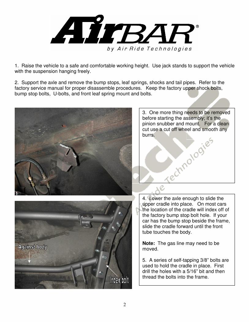
3. One more thing needs to be removed before starting the assembly; it’s the pinion snubber and mount. For a clean cut use a cut off wheel and smooth any burrs.
4. Lower the axle enough to slide the upper cradle into place. On most cars the location of the cradle will index off of the factory bump stop bolt hole. If your car has the bump stop beside the frame, slide the cradle forward until the front tube touches the body. Note: The gas line may need to be moved. 5. A series of self-tapping 3/8” bolts are used to hold the cradle in place. First drill the holes with a 5/16” bit and then thread the bolts into the frame.

3
9. The lower axle bracket will be fastened to the leaf spring pad using the factory U-bolts. It is offset to the inside of the car. New 7/16” nylocs are supplied. 10. Bolt the lower Shockwave mount to the lower holes of the axle bracket if you have a monoleaf car. If you have a multileaf car the bottom of the billet mount will be flush with the axle bracket. 11. Swing the lower bar up to the axle bracket and insert 5/8” x 2 3/4" bolt. The standard hole is the center hole like in the picture. Thread 5/8” Nylok onto the bolt but do not tighten yet. 12. This end of the bar as well as the upper bars are rubber and do not require lubrication.
6. Install the large end of the lower bar (the long one) into the factory spring mount using the factory hardware. Do not over tighten this bolt; it should be snug. The bar is offset to the inside of the car for wheel and tire clearance. 7. This bushing is polyurethane and is lubricated at the factory with lithium grease, additional lubrication is not needed. Future lubrication can be done using any non-petroleum based lubricant. 8. Bolt the bar and mount back onto the car using the factory hardware.
13. Check the length of the upper bar; it should be 9 1/4" C-C. Bolt the axle tabs to the setting jig (The setting jig is explained on the next page) . (Longer ears to the front) Then place the other end of the jig into the cradle. Both ends use a 5/8” x 2 3/4" and should not be fully tightened yet. For now just the let axle tabs sit on the axle. 14. Before welding these tabs to the axle you will need to center the axle and set pinion angle. We used a plum on the outside of the quarter panel to center the axle left to right. Setting the pinion angle is explained on the pinion angle page. This must be done at ride height.
4
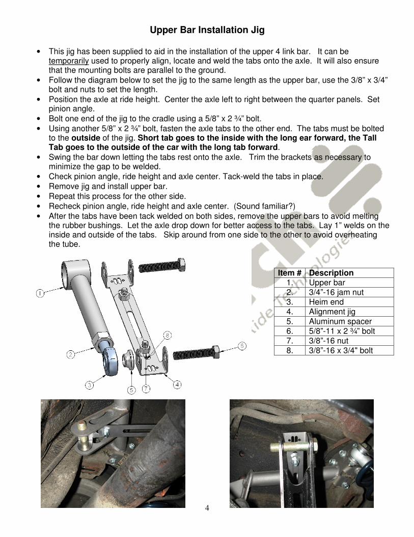
Upper Bar Installation Jig
• This jig has been supplied to aid in the installation of the upper 4 link bar. It can be temporarily used to properly align, locate and weld the tabs onto the axle. It will also ensure that the mounting bolts are parallel to the ground.
• Follow the diagram below to set the jig to the same length as the upper bar, use the 3/8” x 3/4” bolt and nuts to set the length.
• Position the axle at ride height. Center the axle left to right between the quarter panels. Set pinion angle.
• Bolt one end of the jig to the cradle using a 5/8” x 2 ¾” bolt.
• Using another 5/8” x 2 ¾” bolt, fasten the axle tabs to the other end. The tabs must be bolted to the outside of the jig. Short tab goes to the inside with the long ear forward, the Tall Tab goes to the outside of the car with the long tab forward.
• Swing the bar down letting the tabs rest onto the axle. Trim the brackets as necessary to minimize the gap to be welded.
• Check pinion angle, ride height and axle center. Tack-weld the tabs in place.
• Remove jig and install upper bar.
• Repeat this process for the other side.
• Recheck pinion angle, ride height and axle center. (Sound familiar?)
• After the tabs have been tack welded on both sides, remove the upper bars to avoid melting the rubber bushings. Let the axle drop down for better access to the tabs. Lay 1” welds on the inside and outside of the tabs. Skip around from one side to the other to avoid overheating the tube.
Item # Description 1. Upper bar 2. 3/4”-16 jam nut 3. Heim end 4. Alignment jig
5. Aluminum spacer 6. 5/8”-11 x 2 ¾” bolt 7. 3/8”-16 nut 8. 3/8”-16 x 3/4" bolt

5
15. How do you set the pinion angle? On a single-piece shaft you want to set it up where a line drawn through the center of the engine crankshaft or output shaft of the transmission and a line drawn through the center of the pinion are parallel to each other but not the same line. A simple way to do this is to place a digital angle finder or dial level on the front face of the lower engine pulley or harmonic balancer. This will give you a reading that is 90 degrees to the crank or output shaft unless you have real problems with your balancer. At the other end, you can place the same level or angle finder against the front face of the pinion yoke that is also at 90 degrees to the centerline. If you rotate the yoke up or down so both angles match, you have perfect alignment. Road testing will tell you if you have it right. If you accelerate and you get or increase a vibration, then the pinion yoke is too HIGH. Rotate it downward in small increments of a degree or two until the problem goes away. If you get or increase a vibration when decelerating, then the pinion yoke is too LOW. Rotate it upward to correct it.
6
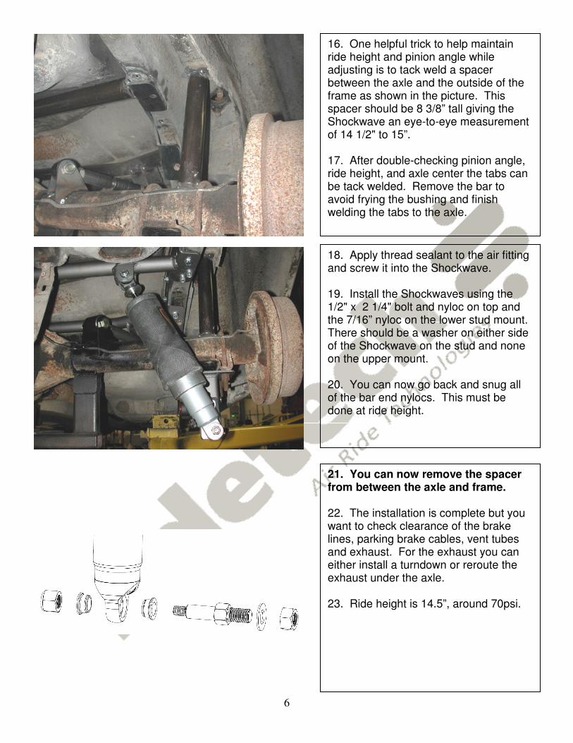
16. One helpful trick to help maintain ride height and pinion angle while adjusting is to tack weld a spacer between the axle and the outside of the frame as shown in the picture. This spacer should be 8 3/8” tall giving the Shockwave an eye-to-eye measurement of 14 1/2" to 15”. 17. After double-checking pinion angle, ride height, and axle center the tabs can be tack welded. Remove the bar to avoid frying the bushing and finish welding the tabs to the axle.
18. Apply thread sealant to the air fitting and screw it into the Shockwave. 19. Install the Shockwaves using the 1/2" x 2 1/4" bolt and nyloc on top and the 7/16” nyloc on the lower stud mount. There should be a washer on either side of the Shockwave on the stud and none on the upper mount. 20. You can now go back and snug all of the bar end nylocs. This must be done at ride height.
21. You can now remove the spacer from between the axle and frame. 22. The installation is complete but you want to check clearance of the brake lines, parking brake cables, vent tubes and exhaust. For the exhaust you can either install a turndown or reroute the exhaust under the axle. 23. Ride height is 14.5”, around 70psi.

7
350 S. St. Charles St. Jasper, In. 47546 Ph. 812.482.2932 Fax 812.634.6632
www.ridetech.com
Should I weld my AirBar 4 link assembly in? Since we get this question quite often, it deserves a proper explanation. The AirBar has been designed for bolt-in installation. We have paid special attention to interfacing with key structural areas of each vehicle, fastening bracketry in at least two planes to properly distribute load paths, and to using appropriate fasteners that roll, rather than cut, threads into the vehicle structure. Having said that, you could potentially encounter a vehicle that has rust or collision damage in these areas. Or maybe you intend to consistently place the vehicle in severe racing applications with sticky racing slicks and high speed corners. In these cases it is perfectly acceptable to weld the AirBar components into your vehicle. Even in these severe cases we recommend that you install the entire AirBar assembly first [including the fasteners], and then use short 1” long tack welds to secure your installation. Remember that the vehicle structure metal is typically much thinner [.060”-.120” ] than the .188” thick AirBar brackets. If you burn through the vehicle sheet metal structure you may end up with an installation that is weaker than before you tried to weld it. The other reason to weld in your AirBar assembly is…you simply want to. You’re a welding kind of guy…that’s the way you’ve always done it…you have the skills and equipment to do it. In that case…weld away with our blessing!