part 23 - small airplane certification process study · · 2009-08-05part 23 – small airplane...
TRANSCRIPT

OK-09-3468
Part 23 – Small AirplaneCertification Process Study
Recommendations For GeneralAviation For The Next 20 Years
July 2009

Part 23 – Small Airplane Certification Process Study
A life-cycle study which assesses the cumulative certification experience and makes recommendations for the next
twenty years.
July 2009
1

2

3

Table of Contents Executive Summary................................................................................................................... 6 Background.................................................................................................................................. 6 Summary of the Findings and Recommendations ....................................................................... 6 Continued Airworthiness ............................................................................................................. 7 Data Management ........................................................................................................................ 8 Pilot Interface............................................................................................................................... 9 Introduction.............................................................................................................................. 10 Background................................................................................................................................ 10 Team Objective.......................................................................................................................... 12 Team Approach.......................................................................................................................... 13 1. Structure and Process of part 23 ................................................................................... 14 1.1 Finding 1.1 ........................................................................................................................ 14 2. Design Certification ........................................................................................................ 30 Overview ................................................................................................................................... 30 2.1 Finding 2.1 ........................................................................................................................ 30 2.2 Finding 2.2 ........................................................................................................................ 33 2.3 Finding 2.3 ........................................................................................................................ 34 2.4 Finding 2.4 ........................................................................................................................ 34 2.5 Finding 2.5 ........................................................................................................................ 36 2.6 Finding 2.6 ........................................................................................................................ 36 2.7 Finding 2.7 ........................................................................................................................ 36 3. Continued Airworthiness ............................................................................................... 38 Overview ................................................................................................................................... 38 3.1 Finding 3.1 ........................................................................................................................ 39 3.2 Finding 3.2 ........................................................................................................................ 42 3.3 Finding 3.3 ........................................................................................................................ 42 3.4 Finding 3.4 ........................................................................................................................ 43 3.5 Finding 3.5 ........................................................................................................................ 43 3.6 Finding 3.6 ........................................................................................................................ 44 4. Data Management........................................................................................................... 46 Overview ................................................................................................................................... 46 4.1 Finding 4.1 ........................................................................................................................ 47 4.2 Finding 4.2 ........................................................................................................................ 48 4.3 Finding 4.3 ........................................................................................................................ 48 4.4 Finding 4.4 ........................................................................................................................ 49 4.5 Finding 4.5 ........................................................................................................................ 50 4.6 Finding 4.6 ........................................................................................................................ 51 5. Pilot Interface .................................................................................................................. 52 Overview ................................................................................................................................... 52 5.1 Finding 5.1 ........................................................................................................................ 52 5.2 Finding 5.2 ........................................................................................................................ 63 Conclusions............................................................................................................................... 65
4

Appendix A - Team Members ................................................................................................... 66 Appendix B - Charter ................................................................................................................ 67 Appendix C - Suggested Expansion Subjects for 14 CFR 21.3 Requirements ......................... 70 Appendix D - Accidents Supporting the Pilot Interface Recommendations ............................. 75 Appendix E - List of Acronyms ................................................................................................ 87
5

Executive Summary
Background The primary objective of the part 23 Certification Process Study (CPS) was to assess the adequacy of the current airworthiness standards throughout a small airplane’s service life while anticipating future requirements. Working groups comprised of various members of the aviation industry were assigned to the five areas of this study to identify issues and develop recommendations. The study was not limited to certification standards; study team members reviewed other topics affecting general aviation including pilot training, operations, and maintenance. The study offers a variety of short-term and long-term recommendations. These recommendations will serve as the basis for a part 23 regulatory review (currently scheduled for FY10). It has been over 20 years since the last part 23 regulatory review. Not only is it time for a complete review of part 23, it is also time to review the original assumptions for part 23, including operations and maintenance. The airplanes being certified today have changed significantly since the inception of part 23 and this evolution will likely continue. Summary of the Findings and Recommendations
Performance Based Standards for part 23
This section of the report addresses performance-based standards for part 23 airplanes. Part 23 currently differentiates airplane requirements based on engine type and airplane weight which does not address the operational capabilities of today’s high-performance small airplane. Historically, part 25 airplanes had technologies that for cost and weight reasons were not practical for part 23 airplanes. Smaller part 23 airplanes were typically simple and slow while bigger airplanes were more complex and faster. Consequently, the existing approach to standards based on weight and engine type was effective. While the existing approach has produced safe airplanes for decades, technological advances have changed the original assumptions of the part 23 divisions. The new small turbine engines, composite airframes, and lightweight digital electronics offer part 23 airplanes the operational capability and performance of traditionally larger part 25 airplanes. Part 23 standards have evolved beyond their original intent to address the increasing performance and complexity. Unfortunately, the slow, simple part 23 airplanes have suffered as the standards have shifted towards more complex airplanes. These findings led to two major recommendations:
• Reorganizing part 23 based on airplane performance and complexity versus the
existing weight and propulsion divisions.
• Rewriting certification requirements for part 23 airplanes as a top level regulation with more detailed implementation methods defined by reference to industry and government standards.
6

Design Certification This section describes the challenges in meeting procedural requirements for the issue of type certificates. It also addresses changes to those certificates and changes affecting the type design of type-certified products and aviation articles like avionics. The bulk of this section and the associated recommendations address the challenges of keeping older airplanes operating safely. This includes upgrading airplanes with better systems (e.g., alternators), newer avionics (e.g., NextGen, navigation, information, or redundancy), and safety gear (e.g., ballistic parachutes and inflatable restraints). A parallel set of recommendations address maintenance of new equipment that the original manufacturer never envisioned being installed on their airplane. The recommendations from this section include but are not limited to the following:
• Updating the Approved Model List (AML) Supplemental Type Certificate
(STC) process to include system interface considerations. • Developing training for the AML/STC process.
• Replacing equipment for “part 23 required equipment” as “approved”
equipment. • Defining major/minor alteration criteria. Developing a regulatory approach to
evaluate changes to the type design consistent for part 21 though part 43.
Continued Airworthiness This section addresses problems associated with airframes staying in service for half a century or more. Considering lengthy service lives, what needs to be done for composites, life-limited parts, and increasingly integrated electronic airplanes? A growing concern for owners of older airplanes involves knowing the service history of parts and components that are sold as airworthy. Few parts have life-limits and even fewer small airplane parts have in-service hours tracked. Existing rules and guidance for the maintenance of part 23 airplanes do not account for the actual age of the airplanes and how the maintenance needs change as the airplanes age. Furthermore, human performance is a dominant factor in general aviation accidents. Accident data historically shows that human performance that includes operators and maintenance personnel attribute to 70 percent to 80 percent of general aviation (GA) accidents. Updating older airplanes with new equipment can address some of these human performance issues, but the FAA needs a vehicle to make addressing the thousands of modifications necessary to the aging fleet of 200,000 GA airplanes easier. The recommendations from this section include but are not limited to the following:
7

• Revising CFR part 23 to include requirements that consider degradation of airplanes, airplane parts, and airplane systems in the Instructions for Continued Airworthiness (ICA).
• Issuing policy that would allow the use of accepted industry or government
standards (ASTM, DOT, etc.) in an alternation or modification of a product that exceeds the original standards created under CAR 3. This policy would also accept the declaration of the material manufacturer with regard to the accepted standard.
• Amending 43.15 to create a hierarchy for the maintenance data used to
maintain part 23 airplanes.
• Reducing repair and modification mistakes by improving the clarity and usability of all technical documentation.
Data Management This section focuses on existing data management tools and our involvement in their evolution. The Data Management working group built on several existing data efforts. A major safety concern is that the average fleet age for part 23 airplanes is already over 40 years old. Furthermore, as newer airplanes age, they will include technologies we have no long term experience maintaining. These technologies include composite airframes and integrated avionics and engine controls that use large numbers of microprocessors. The Service Difficulty Reporting (SDR) program needs improvement. Currently, this program has limited success. Unfortunately, it was built when technology in aviation was limited. So today, many new critical areas need to be added where problems should be reported. Additionally, one of the important elements of the FAA Safety Management System (SMS) effort is developing better tools to conduct Continued Operational Safety (COS) tasks. The Monitor Safety Analyze Data (MSAD) team designed an application to address this need. The MSAD tool relies upon various databases such as the SDR database for both maintenance and operational in-service data to perform quantitative-based analysis to determine the level of risk and appropriate mitigation actions. This requires a more progressive approach to data collection and management. The recommendations in this section include greater involvement with these and evolving programs.
8

Pilot Interface This section addresses sharing information with pilots from both the airplane certification and the training and operations disciplines. The Pilot Interface working group was composed of representatives from the flight test, flight operations, and flight training segments of the industry and FAA. As the findings show, this working group uncovered several disconnects between the certification and operations world. The recommendations address how to share more pertinent information from the flight test process with pilots. The intent is to increase pilot awareness of the data provided through flight testing to ensure pilots understand the information and its limitations. The recommendations from this section include but are not limited to the following:
• Clarifying between FAA Aircraft Certification Service (AIR) and Flight
Standards Service (AFS) the understanding of one engine inoperative (OEI) climb performance development and how it is conveyed during training in weight/altitude/temperature (WAT) performance limited airplanes.
• Agreeing on explanatory language between FAA Flight Standards, flight test,
and structures for pilots to understand published speeds and what protection is actually available to the pilot when complying with these airspeeds.
• Requiring pilot type training to include landing experience on minimum field
length runways, preferably in the simulator, and expose pilots flying small jets to landing on both minimum dry field length and contaminated runways.
• Re-emphasizing the difference between stall warning and aerodynamic stall.
Pilots may fly an airplane for years and never stall the airplane or even feel the stick pusher. Most small airplanes can not recover from an actual stall without pushing the nose down and flying out, which is not currently emphasized in type training.
a. Current FAA training focuses on maintaining pitch attitude and adding power.
b. Even in high-performance jets, there may be some parts of the envelope where the
airplane will not recover from the stall with power only.
9

Introduction This objective of this study was to assess, from the part 23 certification perspective, the adequacy of the current airworthiness standards throughout a small airplane’s service life. The study was not limited to certification standards; study team members reviewed other topics affecting general aviation, such as pilot training, operations, and maintenance.
Courtesy of EAA Background Historically, the FAA has hosted regulatory reviews for 14 Code of Federal Regulations (CFR) part 23 about every 10 years. The two most recent reviews of part 23 were performed in 1974 and 1984. In 1990, a regulatory review was done in conjunction with a harmonization program between the FAA and the European Joint Aviation Authorities (JAA). It has been over 10 years since the last review of part 23. During the preliminary discussions of the part 23 Certification Process Study (CPS), it became clear that it is also time to review the original assumptions for the basis of part 23, with particular emphasis on operations and maintenance. In 2006 there was a meeting between the Small Airplane Directorate and operators of historic military airplanes. Some of these airplanes were used in simulated combat maneuvering and had suffered several in-flight breakups. It became apparent from this meeting that operators of these airplanes did not have a clear understanding of how a certified airplane is designed and how it is impacted by fatigue. One operator stated that if the airplane structure was designed for 6Gs, then they could “pull 6Gs” all the time, on every flight. The operator had no knowledge of the cumulative effects of G-loading on airframe fatigue. This meeting became the impetus for the part 23 study. This meeting showed a need to evaluate the connection between general aviation airplane certification, operation, and maintenance. One task was to identify major “myths” between the different areas of certification, maintenance, and operations. For this effort, the team defines myths as widespread misunderstandings about how something is done. For example, actual structural safety margins versus the certified limits or parts life. Not all CAR 3/part 23 airplane structures are designed using the same approach. CAR 3 or older airplanes may have more “margin” in their structure than new part 23 airplanes. All three areas overlap and are interconnected and that’s where the team started looking for the myths.
10

Maintenance
Certification Operations
A similar study for Transport Category airplanes was completed in 2002. This study focused only on transport airplanes in part 121 air carrier operations. While that study contained valuable findings, many were not applicable to the diverse operations of the general aviation community:
• Owner-flown airplanes to rental fleet airplanes to commercial operations • Vintage airplanes to advanced turbojet powered airplanes • Private pilots to airline transport pilots with type ratings • Small repair shops to large service centers • Round dial instruments (steam gauges) to glass cockpits with synthetic vision
systems
Beyond the existing fleet, the study team reviewed part 23 airplanes (from a top level perspective) and made recommendations based on current and expected future products. Specifically, the study team was challenged to determine the future of part 23, given today’s current products, and anticipated products twenty years from now. This type of forward thinking led to one of the major recommendations from the study: restructure part 23 into performance and complexity based divisions. This study includes a review of the complete life cycle of part 23 airplanes; including all the airplanes in the same weight range that part 23 covers. Airplanes built under the predecessor regulations such as CAR 3 are the certification basis for the bulk of the existing GA fleet. This report uses the term “part 23” to include all GA airplanes in the same class as those covered by part 23. When CAR 3 standards were adopted by the Civil Aeronautics Administration, airplane construction methods and operations were narrowly focused; likewise, their performance parameters were narrow. As aviation technology progressed, construction methods, performance, and complexity have evolved. The Normal, Utility, Acrobatic, and Commuter categories have seen remarkable advances in capability, from the modern day Legend Cub skimming the wheatfields all the way up to the flight levels in a Cessna Citation CJ4. The 2008 Nall Report indicates the total number of accidents in small airplanes in the United States has been on a downward trend since 1998. Additionally, the number of fatal accidents has also decreased during this time. The Aircraft Owners and Pilots Association (AOPA) Air Safety Foundation’s Technically Advanced Aircraft (TAA), Safety and Training Report
11

shows that the use of new cockpit technologies can further reduce the accident rate. The report states that, “TAAs have proportionately fewer accidents compared to the overall GA fleet. TAA have experienced reductions in the percentage of takeoff/climb, fuel management, and maneuvering accidents, but increases in landing, go-around and weather crashes, as compared to the fleet.” For example, no TAA airplanes have had accidents related to fuel management. Many TAA airplanes incorporate the use of a low fuel light or fuel range ring that displays information directly in front of the pilot. This is just one example where the incorporation of technology increases safety.
Even with current improvements in small airplane safety, the FAA believes that further safety gains may come from examining the overall processes applied during the airplane’s lifespan and evaluate how these activities interrelate with in-service operation and maintenance of the airplane. As the US GA fleet passes an average age of 40 years, the processes for continued airworthiness will become more important. Also, almost all new airplane designs incorporate all electric, integrated systems using databus architectures. These airplanes will challenge traditional airplane maintenance, training, and modifying practices. This review, intended as a separate but complimentary effort to Safer Skies, studied the processes and procedures that are currently being applied during the various activities associated with the airplane airworthiness programs. The team also examined how these activities interrelate to the maintenance and operation programs (including training) applied in service.
Team Objective
The objective of this team was to assess the adequacy of the various operations and airworthiness processes currently in place throughout the airplane’s service life, and, if appropriate, to identify opportunities for process improvements. The team has:
• Made recommendations for long-term improvements; and • Encouraged implementation of near-term, easy to address improvements
12

Team Approach
This study started with a request for support from both industry and FAA organizations representing certification, maintenance, and operations. There was substantial support from the different organizations. The effort started with a brainstorming session of the specific issues the team members experienced in their respective areas. The team grouped the specific issues into categories. These categories, with some refinement, became the major sections of this report. A working group was established for each category and members were asked to volunteer for the working group where they felt they could contribute. In many cases, team members were on more than one working group. Each working group compiled their list of issues refining them into findings. In addition to representing their own organization’s interests (such as avionics installations), the team members brought significant personal experience to the study as mechanics, engineers, pilots, instructors, and airplane owners. Thus, it was natural that working groups used personal experience as well as interviews, accident studies, and surveys to make their findings and recommendations. Over a two-year timeframe, there were five face-to-face meetings. In addition to the meetings, the use of telecoms, same-time meetings, and internet document exchange ensured that the objectives were met.
13

1. Structure and Process of part 23
1.1 Finding 1.1
The structure of part 23 is inadequate for today’s airplanes. In the last several decades the part 23 standards have been continuously challenged with the scope of new product designs for a number of basic reasons:
• The products within part 23 have increased to include the widest variation of airplanes than any other airplane design certification regulation in the FAA.
• Part 23 airplanes see the majority of new technologies introduced into aviation first.
• The FAA is only able to promulgate a small number of new regulations each year; rulemaking priority favors large transport airplanes (part 25), making part 23 rulemaking difficult.
Courtesy of EAA
Issue: In order to align part 23 with the broad spectrum of products it reflects and also to assure it can remain current, a strategic change to the structure of part 23 is appropriate. Sub-dividing part 23 into tiers based upon complexity and performance allows the FAA to issue targeted regulations appropriate for each class of airplane. Such subdivisions would also allow the FAA to focus oversight on higher performance and complex products. This concept would be aligned with risk-based resource targeting.
An additional benefit of a tiered structure is the ability to leverage the industry and government standards approach for simple part 23 airplanes. Because so much new technology is introduced in part 23, a structure which can leverage industry and government standards to address new technologies as they
come along alleviates the need for regulating by special conditions and issue papers. The FAA would be responsible for the acceptance of the industry and government standards, and it would maintain control of certification requirements while leveraging the skill and knowledge of the aviation community to develop new methods of compliance.
14

Because of high FAA regulatory workload and the diversity of airplanes, systems, and components there is an unacceptable burden on many segments of the part 23 community. To address this certification environment the FAA has relied upon special conditions and issue papers to assure safety is maintained in light of regulations that have not kept up. But these processes add significant administrative burden to FAA staff and applicants alike. A consequence of the difficult regulatory environment has been the high cost of certification and a corresponding reduction of new entry level products within part 23.
1.1.1 Recommendation – Reorganize part 23 based on airplane performance and
complexity verses the existing weight and propulsion divisions.
1.1.2 Recommendation – Certification requirements for part 23 airplanes should be written on a broad, general and progressive level. A team should determine the exact number of tiers and which complexity and performance divisions to use for segmenting them.
A. A first tier should contain the requirements for low complexity, low-performance airplanes and it should act as a basic starting point for all other categories. These basic requirements could be general with compliance methods maintained in industry and government standards referenced by regulation or policy. The simple product category would naturally fall in a lower oversight risk category allowing the FAA to perform more oversight on products in more complex, higher performance tiers.
B. The next tier incorporates by reference the requirements of the previous tiers and adds unique requirements for medium-complexity, medium-performance airplanes. These requirements could also be general with compliance methods maintained in industry and government standards that are referenced by regulation or policy. The next product category would naturally fall in a mid oversight risk category which would require a moderate level of oversight.
C. A highest tier incorporates by reference all of the requirements of the previous tiers and adds unique regulatory requirements for high-complexity, high-performance airplanes. While this tier could leverage industry and government standards, this tier would also allow regulations to attain a level of priority and reliance on more specific regulations. The highest product category would naturally fall in an elevated oversight risk category that would require an increased level of oversight as compared to the more simple categories. The standard of care for attention to human factors related to maintenance and operation also increases as the tier increases.
1.1.3 Recommendation – Coordinate this proposal internationally with aviation regulators to assure it becomes a global standard for the design and certification of airplanes weighing 19,000 pounds or less.
15

1.2 Background
Part 23 evolved from bulletin 7A followed by Civil Airworthiness Regulation 3. Bulletin 7A (1934) states “These requirements are based on the present development in the science of airplane design. Experience indicates that, when applied to conventional types of construction, they will result in airworthy and well proportioned airplanes.” The intent of today’s requirements is exactly the same as they were in 1934 as stated by bulletin 7A. However, over the last decade the science of airplane design has outpaced the current requirements. Additionally, in the 70 years since bulletin 7A the regulations have continually become more prescriptive in reacting to specific design features of the day. The result of the combination of all of these specific rules is the loss of the original intent of airworthiness design regulations and a lack of flexibility to quickly address today’s airplanes.
The DC-3 is frequently considered the first production transport airplane. It seated 21 passengers and had a gross weight of just over 25,000 pounds. During the same era, the largest “light twin,” the Beech 18, weighed about 8,000 pounds fully loaded. Legend has it that the originators of CAR 3 selected a reasonable weight division of 13,000 pounds that was roughly between what they considered the largest “small” airplane and the smallest “large” airplane. Because 13,000 pounds is an ‘unlucky number’ legend goes on to say the originators of CAR 3 selected 12,500 pounds as a division point. Whether this legend is accurate or not it has merit in its illustration that the division of products by weight may make sense when looking at existing products, but the approach loses validity as products evolve beyond what was envisioned. In the 40 years following this division of regulations some basic changes came to airplane and engine design. Fuselages transitioned from simple tube and fabric designs to engineered semi-monocoque aluminum, reducing drag and improving durability and maintainability. Engine technology transitioned from radial to horizontally opposed designs, significantly reducing drag and weight as well as increasing the reliability of airplane propulsion. In the 1970’s, a new airplane emerged for the airline feeder routes. That airplane was the 19-passenger turboprop. The decision was made to use the certification standards for this new class from part 23, supplementing many sections with part 25 Special Federal Airworthiness Regulation (SFAR) requirements. After several SFAR documents, this new set of “commuter” requirements ultimately ended up in part 23 as the commuter category. This was essentially the last fundamental change to the regulations and resulted in the part 23 that exist today. From the 1930s to the 1980s the basic regulations for airplanes weighing equal to or less than 19,000 pounds have served the industry well. In 1984 the last part 23 regulatory review was conducted with participation from industry. During the time between the regulatory review and the issuance of regulatory changes to part 23, the industry experienced a significant downturn and as a result,
16

there was limited participation from industry as the recommendations were developed into proposed regulations and promulgated into final rules. Between 1994 and 1996, approximately 800 rule changes to part 23 were enacted. The rule changes ranged from corrections, to harmonization with European rules, to rules that addressed new technologies of the time. While these changes addressed the needs of more sophisticated part 23 airplanes, they made it more costly to certify a simple airplane. Essentially the regulatory scope of part 23 has been shifted to more directly address the complex airplanes to the detriment of simple airplanes. The following chart illustrates the increased introduction price and corresponding lack of new 4-seat entry-level airplanes introduced in the past few decades. There are certainly other factors that have driven up the price; however the increased difficulty of certifying new entry-level airplanes is clearly one of them.
In the past two decades, airplane construction, engine design and the expanded use of non-mechanical systems has exponentially increased the availability of lightweight and relatively low cost technology in part 23 airplanes. General Aviation (GA) is seeing fast piston airplanes, slow turbine airplanes and simple single-engine jets, etc. As a result the weight and propulsion assumptions used throughout part 23 which have carried us through the first 50 years of flight don’t hold true for today’s designs. While inefficient, through the selective use of special conditions, issue papers and other policy, the FAA has provided an acceptable level of safety as verified by service experience. It is time to assure the design standards, from the simplest to the most complex, “are based on the science of airplane design” as bulletin 7A so eloquently stated.
17

1.3 High-Level Structural Issues with part 23 Code
A number of factors have resulted in part 23 becoming increasingly misaligned with the new airplanes being certified. These factors include difficulty in issuing new regulations, an extremely diverse mix of airplane types and operations, and new technology introduction. This study was an opportunity to review all of part 23 against the expected future airplane life cycle issues.
1.3.1 Issuing New Regulations
The FAA is an executive federal agency; therefore they follow the Administrative Procedures Act (APA) when issuing new regulations. APA assures agencies keep the public informed of their procedures and rules, to provide for public participation in the rulemaking process and to establish uniform standards for the conduct of formal rulemaking and adjudication. The APA process includes a significant number of procedural hurdles to protect the public and assure new regulations are appropriate. The process also adds a significant administrative burden, which means only a select few new regulations can be implemented each year. Streamlining the rulemaking process would be the best solution to assure that part 23 remains current, however, such a change is outside of the scope of the recommendations in this report.
1.3.2 Diverse Mix of Airplanes and Operations
The diverse range of products and operations within part 23 make it very difficult to create regulations that properly address various segments. The scope of products within part 23 has grown significantly since the regulations were created. In part 23 production today are fixed-wing airplanes from small single-engine pistons to turbine-powered commuter category airplanes that can weigh up to 19,000 lbs.
18

Because the new airplane designs within part 23 are so diverse the regulations have become complex. The regulatory structure of part 23 makes it difficult to create regulations to address the projected target. Often these regulations are written in a broad manner and they have unintended consequences on products of a different size and complexity. While not impossible, certifying a simple, two-place airplane is cumbersome and expensive. At the same time, part 23 doesn’t completely address very complex high-performance turbine products. Today, the FAA utilizes special conditions to address the certification requirements of complex high-performance turbine airplanes. A wide range of products makes it very difficult to target regulations at the correct population of airplanes, and product sub-divisions within part 23 would benefit the certification process. For the aviation industry to continue to thrive in the United States in the safest manner possible, it needs to attract new pilots to general aviation. The Light Sport Aircraft (LSA) should help attract new pilots, but LSA airplanes do not have the utility available in part 23 airplanes. Pilots wanting more utility than LSA are still learning to fly in 30-year-old Cessna’s and Pipers. As pilots transition from LSA to part 23 airplanes it is advantageous to start new pilots in airplanes using the new safety technologies that have become common. Over the last decade the number of active private pilots has been declining and the number of new pilot starts hasn’t kept pace. Revitalizing the entry-level airplane market can have a beneficial effect on attracting new pilots in the safest manner possible.
19

Historically, division points such as weight and propulsion type have been used to differentiate product types however these differentiators are becoming increasingly invalid. It can no longer be said that light weight airplanes are all simple with low performance because of improvements in systems design and the increasing use of integrated electronic systems. Similarly, the near future will see single-engine turbofan airplanes with performance comparable to traditional piston twin airplanes. The weight and propulsion type assumptions in part 23 are valid on about half of today’s new products. In looking forward to the next 20 years, the FAA should move away from historical assumptions and base requirements on airplane complexity and performance.
1.3.3 New Technology Introduction
The number of new technology devices introduced for part 23 airplanes increases every year. This has been going on now for more that a decade. The introduction of new technologies such as integrated cockpits, moving map displays, and Wide Area Augmentation System (WAAS) Global Positioning Systems (GPS) have been credited for significant advances in the safety record of general aviation airplanes. According to Nick Sabatini, Retired Associate FAA Administrator for Safety, addressing the record low number of fatal GA accidents (while holding his FAA position), “This record is due to a dedicated commitment to safety by everyone in general aviation. In particular, manufacturers are providing sophisticated technology like GPS and glass cockpits, and the training to go with them, and the FAA is vigorously encouraging adoption of these safety enhancements.”
20

Furthermore, according to the AOPA’s Air Safety Foundation (ASF) report, “Technologically Advanced Aircraft, Safety and Training” from 2007, airplanes incorporating this new technology have proportionally fewer accidents when compared to the overall GA fleet. While the number of variables associated with GA accidents makes the direct correlation between new technology and fewer accidents impossible, some level of correlation is likely. Even with all of the available new safety technology, pilots are still blamed for fatal accidents. Worth noting is that the ASF report points out that “poor judgment will always be poor judgment.” It is expected that over the next two decades the introduction of new part 23 technologies, including additional life saving technologies, will continue to accelerate. This is good news for GA, but it increases the FAA oversight burden. The FAA must develop new regulatory, policy and guidance materials to address such technologies. Continuing to address these items on an installation-by-installation basis through issue papers and special conditions will delay the introduction of safety enhancing technologies.
1.4 Recommendations to Change the Structure of part 23
Restructure part 23 to align it with new designs while maintaining the basic requirements within the code today. The assumptions of propulsion and weight have become outdated; break part 23 into tiers based on performance and complexity. Furthermore, it is unlikely that part 23 rulemaking will be able to keep up with new technology, so the new structure should be organized in a way that leverages industry and government standards. The industry and government standard concept envisioned resembles standards developed for part 25 systems and avionics. This system addresses the most critical systems and gives the FAA final approval authority. Also, they can be quickly
21

developed with the assistance of international regulators and industry experts. A tiered structure will also support risk-based resource targeting to assure the FAA can spend the majority of its safety resources on oversight in areas where risk is higher.
1.4.1 Tiered Regulatory Structure
The FAA’s Small Airplane Directorate standards staff has, on numerous occasions, explored the possibility of moving from current requirements to standards based on performance and complexity. But the effort has been simply too large to undertake without a dedicated team and priority. To be most effective, product sub-divisions should be based upon the characteristics of complexity and performance as these are the items which have a direct effect on safety. Part 23 is so broad that it is difficult for the FAA to address one area positively without having negative impact in another area. A tiered system based on performance and complexity provides the FAA with divisions within which the agency can appropriately address the range of products. Conceptually, a three-tiered system will address the scope of products within part 23 that exist today and those envisioned in the next 20 years. The team recommends that further study go into determining the optimum number of tiers. This study proposes the following:
• Low Complexity, Low Performance • Medium Complexity, Medium Performance • High Complexity, High Performance
It is important to have both complexity and performance differentiators as these are the physical items which affect safety and drive unique regulatory requirements. Increasing systems and systems integration is directly related to complexity and the need for more sophisticated safety analysis requirements. Similarly higher performance results in more varied operational environments and airframe considerations relating directly to certification requirements. For many decades regulators around the world have used weight and propulsion type assumptions as a measure of complexity and performance but these assumptions are based upon designs of the past and they are no longer valid. As an example, we are beginning to see more simple airplanes relying on turbine engines. It doesn’t make sense to penalize these simple products in the certification requirements because they utilize a propulsion type historically used on higher performance airplanes. Basing product sub-divisions on complexity and performance can provide a more accurate and reliable way to address regulatory intent.
22
An additional benefit of tiered regulatory requirements is the ability for the FAA and manufacturers to quickly assess what new requirements would apply to derivative products. Manufacturers commonly grow a product line based upon the certification of derivative airplanes. A tiered system supports this activity by clearly differentiating additional requirements as complexity or performance increase. Finally, a tiered system of regulations would assist the FAA in moving towards a risk-based approach to safety oversight. Through this system, products with higher design risk fall in higher oversight categories aiding the FAA in risk-based oversight. The following tier divisions are offered to convey the tier concept. A thorough discussion of past, present and future products should be conducted to determine the appropriate number of tiers and also those factors which should be used as division points for performance and complexity. Another factor that should be considered is the number of passengers. Historically, there has been a division between 9 or less and 10 or more.
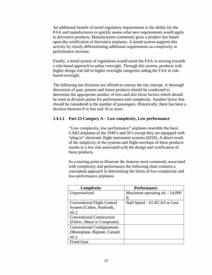
1.4.1.1 Part 23 Category A – Low complexity, Low performance
“Low complexity, low performance” airplanes resemble the basic CAR3 airplanes of the 1940’s and 50’s except they are equipped with “plug-in” electronic flight instrument systems (EFIS). A direct result of the simplicity of the systems and flight envelope of these products results in a low risk associated with the design and certification of these products. As a starting point to illustrate the features most commonly associated with complexity and performance the following chart contains a conceptual approach to determining the limits of low-complexity and low-performance airplanes:
Complexity Performance Unpressurized Maximum operating alt. - 14,000
ft. Conventional Flight Control System (Cables, Pushrods, etc.)
Stall Speed – 61 KCAS or Less
Conventional Construction (Fabric, Metal or Composite)
Conventional Configurations (Monoplane, Biplane, Canard, etc.)
Fixed Gear
23

By limiting complexity to conventional flight controls, construction, configuration and fixed gear, the FAA can easily identify basic safety standards for this product type without complicating the certification process with regulations intended to address other products. Restricting maximum altitude to 14,000 feet is based on oxygen requirements and will more closely align these airplanes with operating regulations.
Courtesy of Cessna Aircraft
Unlike Light Sport Aircraft (LSA) and ultralight standards, a maximum speed isn’t considered. Limiting the stall speed creates a reasonable upper speed limit. Stall speed is the one of the most import safety limitations for this class of airplane. Unless a manufacturer incorporates a very complex flap or other high lift design, most fixed-gear airplanes in this class are only capable of about three times the stall speed. FAA certification standards should serve as the repository for the lessons learned and best industry practices for building small airplanes. The part 23 design standards should be the basis for any standard, accounting for the escalation of requirements and tests. Even considering that requirements seldom meet ideal expectations because of external factors, the bulk of the pre-1984 part 23 requirements contain the combined wisdom of decades of airplane certification and would be a good starting point for the first two classes. The requirements would need to be thoroughly reviewed and applied as appropriate. Furthermore, thought should be given to how this approach might simplify issues where airplane parts are manufactured outside the continental United States. The first category would allow development of a basic set of regulations designed to address this type of product without being overly burdensome or complicated. For example, the simplicity of this class of airplanes would allow for more simple failure analysis as a result of the very simple system interactions and basic characteristics that these designs contain. Also, develop best industry design practices to replace expensive testing for concerns like lightning protection and dynamic seat qualification.
24

1.4.1.2 Part 23 Category B – Medium Complexity, Medium performance
A medium-complexity, medium-performance airplane might include the following characteristics:
Complexity Performance Conventional Flight Control System (Cables, Pushrods, etc.)
Maximum operating altitude - 25,000 ft.
Conventional Construction (Fabric, Metal or Composite)
Maximum Speed, MD – 0.6 M
Conventional Configurations (Monoplane, Biplane, Canard, etc.)
The addition of systems such as retractable gear and pressurization raises design complexity and the regulations needed to address these issues. Conceptually a category B airplane would meet most (or all) of the requirements for a category A airplane plus the additional requirements of a category B airplane. Higher speeds and altitude capability increase the criticality of failures, so category B airplanes would have added requirements to address these capabilities. An altitude limitation of 25,000 feet provides a good natural break for existing structural requirements for pressurized airplanes.
Courtesy of Wikipedia
This category also allows more reasonable standards for the slower, single-engine turboprops and jets. The team envisions this class of jet to offer replacement utility for existing light twins. This class of jet should be easier to fly when compared to the
light twins and that feature alone would offer a safety advantage. While any proposed standard would provide a higher level of safety than that used for the existing fleet of light twins, it would not be so high as to discourage the development and production of single-engine jets.
25

1.4.1.3 Part 23 Category C – High Complexity, High performance
The final category would address all airplanes which exceeded category A and category B criterion:
Complexity Performance Unlimited Unlimited
This category allows for all airplanes that have performance greater than VD of 0.6M, operational capability above 25,000 feet, and any complexity above those of category A and B. This may encompass any part 23 airplane, from a 2-place trainer up to a 19-seat, 19,000 pound aircraft that does not fall into category A or B. This standard is proposed to be the most rigorous and would include most or all of the requirements of category A and B with additional FAA regulations specific to this class of airplane. Development of this category should include a review of the FAA’s cancelled part 24 standard for jets up to 50,000 pounds because many of the ongoing issues are discussed in that
document. Also, the development of this category should include discussions with the FAA’s Flight Standards Service so that relevant operating requirements are considered.
Courtesy of Cessna Aircraft
The European operating rules don’t differentiate between private and commercial jets. This means that current jet projects have a disconnect between operations in the United States and in Europe, and manufacturers are having to design to two standards. Also, in the current U.S.
operating rules, all part 121 operations have to use part 25 airplanes. The proposed high-performance category should be developed to include requirements to will allow airplanes in this category to be acceptable for part 121 operations. This should also allow harmonization with foreign airworthiness authorities, benefiting manufacturers in that they only have to make one airplane.
26

1.4.2 Better Utilization of Recognized Industry and Government Standards
It is unlikely that part 23 will be able to keep up with the rapidly evolving technology in the GA market. Industry develops and maintains standards with resources from regulators around the world alongside of international industry experts. This allows for the rapid development of standardized compliance methods for new technologies. The FAA should consider using high-level, performance-based regulatory requirements to approve the use of specific industry and government standards to address the detailed implementation of specific technological solutions. Today, the FAA utilizes similar industry standards through policy and guidance documents. Many part 25 avionics and systems are approved using industry and government standards. Setting high-level requirements that are implemented through industry and government standards allows the FAA to have total control over design requirements while giving the agency flexibility and quick adaptation to address new product developments. Through such an approach, the FAA would always maintain control of the approval to use the standards and compliance methods. The FAA would also determine if future revisions are applicable. Maximizing the use of acceptable industry and government documents also keeps in line with pubic law 104-113, which requires government agencies to make use of public standards where ever possible. It’s important to note that the use of industry and government standards is not abdication of the regulations by the FAA. The FAA must continue to maintain control over part 23. It is not envisioned that manufacturer’s would be allowed to self-certify their part 23 airplane. Until the FAA approves the use of the industry and government standards, it is simply a documented process which has no regulatory credibility. The need for individual issue papers and special conditions to address new technology will certainly remain; however, the use of industry and government standards should reduce the need for repetitive special conditions and issue papers. Timely revision of industry and government standards should eliminate a significant administrative burden. Over the last several decades the use of industry and government standards has grown by regulators around the world because they represent a quick way to develop safe methods of design compliance for new technologies. The FAA has an opportunity to formalize the use of industry and government standards in the part 23 regulations thereby increasing the agencies flexibility to adapt the future changing environment of part 23.
27

1.4.3 Risk Based Oversight
In addition to setting the design requirements for the certification of new airplanes, the FAA also performs oversight of the manufacturers to assure the design requirements are being met in a consistent and correct manner. It is the goal of the FAA to focus more heavily on areas where compliance is more complicated and where it provides the biggest safety benefit. Through the development of a tiered set of regulations the FAA would have more flexibility determining which products should have higher levels of oversight and which should have more basic levels of oversight. In the proposed tiered system, the FAA would focus more oversight time and effort on the tier with the highest complexity/performance airplanes when all other factors were equal. Certainly applicant experience, level of delegation and uniqueness of design would play a role in such a determination.
1.4.4 International Coordination
Today, aviation products certified and manufactured in the United States are nearly always sold internationally, and when this occurs, the designs must be certified (or validated) in the country where the design will be sold. Similarly, when airplanes made by foreign manufacturers come into the United States, the FAA must approve those airplane designs before they can be registered here. As a result of this global environment, there is a tremendous benefit in working toward regulatory similarity around the world. In order for a restructuring of part 23 to be successful, it must involve the aviation regulatory agencies from around the world. This will assure the part 23 changes are readily accepted internationally. Furthermore, such coordination assures the FAA can easily review airplanes certified by foreign authorities to assure they meet similar safety requirements.
1.5 Conclusion
In recent decades the part 23 standards have not kept pace with the scope of new product designs for a number of basic reasons:
• The products within part 23 have increased to include the widest variation of any other airplane design certification part.
• Part 23 airplanes are first to see the majority of new technologies being introduced into aviation.
• The FAA is only able to promulgate a small number of new regulations each year and rulemaking priority favors large transport airplanes (part 25), making part 23 rulemaking difficult.
28

In order to align part 23 with the broad spectrum of products it reflects and also to assure it can remain current, a strategic change to the structure of part 23 is appropriate. Sub-dividing part 23 into tiers based upon complexity and performance allows the FAA to issue targeted regulations appropriate for each class of airplane. Such subdivisions would also allow the FAA to focus oversight on higher performance and complex products. This concept would be aligned with risk based resource targeting. An additional benefit of a tiered structure is the ability to leverage the industry and government standards approach for simple part 23 airplanes. Since so much new technology is introduced in part 23, a structure that leverages industry and government standards to address new technologies as they come along reduces the need for regulating by special conditions and issue papers. The FAA would still have responsibility for regulatory acceptance of industry and government standards. The FAA would maintain control of certification requirements while leveraging the skill and knowledge of the aviation community to develop new methods of compliance.
This recommendation will potentially have ramifications across multiple regulations and disciplines. It will likely affect parts 21, 23, 91, and 135. The FAA, when considering the implication of this recommendation, should include all of the organizations that could benefit from the part 23 restructuring.
29

Courtesy of EAA
2. Design Certification
Overview
This section describes the challenges in meeting procedural requirements for the issue of type certificates. It also addresses changes to those certificates and changes affecting the type design of type-certified products and aviation articles like avionics. The bulk of this section and the associated recommendations address the challenges of keeping older airplanes operating safely. This includes upgrading airplanes with better systems (e.g., alternators), newer avionics (e.g., NextGen, navigation, information, or redundancy), and safety gear (e.g., ballistic parachutes and inflatable restraints). A parallel set of recommendations address maintenance of new equipment that the original manufacturer never envisioned being installed on their airplane.
2.1 Finding 2.1 There are numerous shortcomings in the Approved Model List (AML) Supplemental Type Certificate (STC) process that need correcting.
Issue: The traditional approach to modifying an airplane is to use the STC process. More
recently the FAA’s Small Airplane Directorate published guidance for modifying large numbers of airplanes. That process is called the Approved Model List (AML)-STC. This process was not intended to diminish the safety requirement of each modification but to capitalize on the commonality of large numbers of part 23 airplanes. The intent of the AML was to safely streamline the STC process and speed up installation of new, safety enhancing equipment. Unfortunately, there is a lack of understanding by FAA and industry concerning the amount of FAA involvement and the requirement for various types of AML-STCs.
An STC is the FAA’s approval of a major change in the type design of a previously type
certified product. An STC is classified as either “one-only” or “multiple.” The traditional STCs are classified as “one-only” STCs for modification of a specific serial numbered aircraft, aircraft engine, or propeller, and “multiple” STCs when the applicant intends to modify two or more aircraft, aircraft engines, or propellers.
30

STC approvals using the AML process have the same data requirements as standard STCs
for a single airplane model. Traditional avionics installations relied on “field approvals” using this data from the single STC for multiple approvals where similarity can be clearly shown. However, the additional approvals were often carried out with little or no follow-on ACO involvement, which may only be suitable for simple installations where part 43 “acceptable data” clearly addresses differences between the existing approval and the follow-on installation.
For more complex avionics installations the AML process requires the applicant to
address interface considerations to existing equipment upfront for each proposed model. This listing of interfaced equipment has typically been contained in the text of the STC. This includes items that are recommended, acceptable and prohibited interfaces.
STCs are issued for a make of airplane; multiple STCs list “applicable models.” The AML process takes this concept one step further and lists approved make/model of airplane. While the AML process is intended to streamline large STCs, it is not easy to make additions of approved/compatible interfaced equipment with previously installed avionics components.
Furthermore, the listing and limitations of equipment interfaces is not always obvious to the installer. There are a number of cases where avionics equipment is connected to existing equipment by the avionics shop but the STC applicant had not validated the equipment combination. These situations resulted in the altered airplane being subjected to operating limitations. An example of this is where a technician connected a horizontal situation indicator (HSI), which was not validated by the STC applicant, with a new GNSS/WAAS receiver. The glide slope indicator appeared to work, but did not display proper glide slope trajectory or position. The result was a limitation against using the glide slope for GPS until the situation was corrected. 2.1.1 Recommendation:
The FAA needs to amend the AML-STC process to add an Approved Interface List separate from the STC but similar to the AML list. The manufacturer will develop this list and include any critical system. For example, an audio panel is probably not a critical interface, but ADS-B, autopilot, GPS, etc. would probably be considered critical depending on the input criteria. For example, generic interface criteria for the STC text would address it; for prescriptive product interface the approved interface list would address it.
• The FAA needs to amend the AML-STC process to develop procedures for
installers and manufacturers to amend equipment to the approved interface list.
31

• The FAA needs to amend the AML-STC process to develop procedures for installers to install equipment not listed in approved interface list. This is to address situations where the deviations from the installation are minor.
2.1.2 Recommendation
The AML-STC installation manual should list when and where the STC-holder expects the installer to augment the STC with acceptable data. For the majority of installations addressed by an AML-STC process, an example of acceptable data would be AC 43.13.
Issue: The AML-STC is a hybrid STC unique to equipment in part 23 airplanes. The original concept of the AML-STC bridged the gap between the traditional avionics installation approach of utilizing an initial OEM generated one and using an STC followed by field installations using a follow-on “field approval.” The original follow-on installation was approved at the FAA field inspector level using the field approval process. This AML-STC process bridged the gap between lack of ACO oversight of follow-on installations and the redundant paperwork approval at the Aviation Safety Inspector (ASI) level without value added. When originally envisioned, the AML-STC process was for simple stand alone avionics of the late 1990 rather than the fully integrated systems of the early 2000’s. Unlike the current multi-model STC which is completely prescriptive, the AML-STC was designed to be prescriptive where necessary while being general where flexibility is permitted to better serve the diverse GA fleet. The AML process is key to addressing the volume of modifications needed to keep the existing fleet of part 23 airplanes operating safely. The differences between the traditional STC processes and the flexibility of the AML process require a training program developed for FAA and industry to prevent the mistakes of the past. 2.1.3 Recommendation
Develop and implement ACO, industry, and installer (and any other appropriate group) training for the use and issuance of AML STCs.
• FAA Engineers need to complete an internal training program before
receiving AML-STC issuance authority similar to Flight Standards required training for issuing field approvals.
• Flight Standards needs to develop training for AML-STC installation oversight.
• FAA should encourage industry to continue public education on AML-STC installation and usage.
• FAA should incorporate training for the use of AML STCs into the FAA Safety Team (FAAST) Airworthiness Training agenda and at FAA DER seminars
32

Issue: Flight Standards policy on field approvals does not address follow-on field approvals based on AML-STCs. There are instances where a specific airplane might not be listed on the AML. The data may be acceptable and applicable for a specific alteration but needs to be approved for a major alteration. The flight standards ASI should be able to perform a field approval utilizing data just like any other follow-on field approval to an STC.
2.1.4 Recommendation
An AML-STC is still an STC. The small airplane directorate needs to work with flight standards to develop policy to address “follow-on” field approvals to AML-STCs that can be handled just like would be done for an STC.
Issue: The AML-STC process (AC 23-22) assumes that the installer will make non-safety critical amendments to the STC data package utilizing FAA acceptable data. The FARs do not support this mixing of data for major alterations. Section 65.95 allows the holder of an A & P with an inspection authorization to inspect and approve for return to service any airplane after a major repair or major alteration provided the work was done in accordance with “approved” technical data. The AML-STC utilizes “approved” specific data as part of the STC and allows for the generic use of “acceptable” data to allow for broader applicability of the AML-STC to the variability of general aviation fleet. The FARs currently do not recognize the use of hybrid (partially approved – partially accepted) data.
2.1.5 Recommendation
The regulations (either part 43 or part 65/145) need to be amended to allow for the use of these hybrid data.
2.2 Finding 2.2 Today, replacement equipment is not required by regulation to have a TSO, PMA, or FAA approval. For example, an attitude indicator could be replaced by any device that resembles the attitude indicator in form, fit, and function but does not meet any design standard. This was not the intention of the rules, and required equipment should meet a known standard. Replacements for required equipment under part 23 need to be “approved” per part 21.
Issue: “Required equipment” by definition is required for safety. The installer who is installing replacement equipment does not have the ability to adequately address performance “function” with respect to “non-approved” replacement equipment. This recommendation is intended to address equipment as listed in 23.1303, 23.1305, and 23.1307 and not to impact the mechanic’s ability to make minor repairs.
33

2.2.1 Recommendation:
Replacement equipment for “part 23 required equipment” should be “approved” as defined in 21.305.
2.3 Finding 2.3 The FAA requires ICA’s for original equipment (21.50) and ICA’s for modifications. The FAA does not require changes to the original ICA that result from the modifications to the original equipment.
Issue: Issuance of STCs not compatible with the original operations and maintenance of the specific airplane being modified. The changes do not adequately address the altered airplane or systems ICA. For example, the BRS installations in the baggage compartment of C-172 that limit the access to the aft fuselage/tail section. This affects the inspection of avionics, batteries, flight control cables, and corrosion control of the aft fuselage section. The BRS ICA addresses the continued airworthiness of the BRS system but does not address the changes necessary to continue to maintain the altered airplane or systems.
2.3.1 Recommendation: Add the requirement to evaluate the affect of an alteration on the existing ICA/maintenance programs as a function of developing amended ICAs.
2.3.2 Recommendation:
The FAA should consider a process for developing, managing, and approving a supplemental ICA/ICA supplement process similar to what is done today for a supplemental AFM/AFM supplement.
2.4 Finding 2.4 There are alterations listed in part 43 appendix A that exceed the minimum criteria requiring an STC in part 21 section 21.113. Issue: The definition of Major Change in Type design (21.95) is the same as a Major Alteration (part 1) resulting in conflicting application of approval of alterations. The list of alterations that are a major alteration (part 43, Appendix A) are in conflict with the criteria requiring an STC (21.113). In-service airplanes are modified regularly and there’s a history of modifications being done under field approvals that should have been done as an STC. These airplanes are modified legally under part 43, but these part 43 modifications would have required an
34

STC had they been modified against part 21. There are thousands of staff hours spent processing field approvals and records of major alterations because the lack of clarity of the definition of a minor alteration. The criteria for major alterations dates back to the Civil Aeronautics Regulations (CARs) with little updating since the early 1950s. A major alteration is a change to the original (or properly altered) type design. The Small Airplane Directorate should review and manage the items listed in part 43 designating a major alteration.
FAA Order 8110.46 (Major Alterations, 09/30/2002) defined the criteria of the six critical elements of major change to a type design (which corresponds to six criterion of major alteration). But the order was rescinded when the FAA issued the field approval guidance under Order 8300.10. Order 8300.10 has now been incorporated into the Flight Standards Information Management System (FSIMS) (Order 8900.1, effective date 9/13/2007). The words defining the scope of the six critical criterions only reside in this rescinded document. The new order used a matrix based on the intent of the words. The old list was more useful in the field and needs to be brought back.
2.4.1 Recommendation The FAA needs to assemble a team to review the conflicts as described in the issue. This team needs to review the following:
• Certification standards and validation of conformity rests with
certification. But Flight Standards is responsible for part 43 which is the primary guidance for modifications to an airplane. Certification should be providing the information for what is considered major in part 43.
• Develop a regulatory approach to evaluating changes to the type design
that is consistent from part 21 though part 43. This allows for an evaluation for a change (alteration) from the highest level of certitude (STC) to the lowest level (minor alteration).
• Amend part 43, Appendix A, to eliminate conflict with part 21.93.
2.4.2 Recommendation
The FAA should re-assign oversight responsibility for alteration regulatory criteria (part 43, Appendix A) to the certifying directorate.
2.4.3 Recommendation Use the definitions from Order 8110.46 in a new document or reissue the applicable portion of the order in a document like Order 8300.10 (NOTE - Order 8300.10 has now been incorporated into the FSIMS (Order 8900.1, effective date 9/13/2007).
35

2.5 Finding 2.5 There is no procedure for removing a flight manual supplement after equipment has been removed. Once that supplement has been approved as part of the AFM, the document can not be legally changed, i.e. the supplemental can not be removed without subsequent approval.
Issue: Current policy adequately addresses the requirement to “add” data to the flight manual. There is no guidance on amendments to the flight manual when a component is removed, (i.e. avionics).
2.5.1 Recommendation
Need a working group to develop policy procedures to address the revision/removal of AFM supplemental material and to define alterations that would require supplements. (ref. FAR 23.1581)
2.6 Finding 2.6
In-service installers are being held to a higher standard of Airplane Flight Manual Supplement (AFMS) approval than the original aircraft manufacturer.
Issue: Section 23.1581 allows for “acceptability” of non-limitation sections of a flight manual; however, field level AFMS are treated to the same level of review and approval. AC 23-8 describes the process for submission, review and acceptance of flight manual supplements. These procedures require explicit review and acceptance – i.e. approval.
2.6.1 Recommendation
AC 23-8 should be revised for flight manual supplements for equipment (23.1585) to allow for the “acceptability” as allowed for in 23.1581 (b).
2.7 Finding 2.7
Airplane Flight Manual Supplement (AFMS) are being added for non-essential equipment.
Issue: AFMS are being approved by FAA Flight standards for simple devices like a tach, ELT, or new fuel pump. This particular issue ends up taking more time and resources, both FAA and installer, than all the other recommendations in this section. This problem may have started with GPS installations because they didn’t include many of the basic limitations that the Airman’s Information Manual (AIM) originally had for traditional avionics. This particular problem creates no-value-added paperwork and workload for FAA and industry.
36

2.7.1 Recommendation AFMS should only be required for “essential equipment” and should not be required for information already contained in the AIM.
37

Courtesy of AEA
3. Continued Airworthiness
Overview
Aircraft certification standards create a set of parameters within which an airplane will have predictable flight and structures performance. These standards are created using technical data obtained through research, including measurable lessons learned from the previous design and operational history of airplanes. Certification standards create a level of design safety acceptable to the operator, maintainer, and public safety. The first priority and most important function of any safety management system is to prevent accidents. Continued airworthiness is a principal component of safety management. By periodic inspections and regular and preventive maintenance and, the airplane is judged to meet its type design and remains in a safe condition for flight, thus it is considered airworthy. Overseeing the continued airworthiness of the existing fleet of airplanes serves key concerns. These include identifying, analyzing, and providing mitigation for specific safety issues. The continued airworthiness process is also important for validating the certification requirements themselves. Lessons learned in conducting the responsibilities of continued airworthiness improve regulations and standards for type certification. Improving the continued airworthiness process is critical to improving safety in the short term. It is also important for long-term improvements to the certification requirements benefiting future designs. It is important to note that often the work of certification has more resources than continued airworthiness. A better balance is needed to guarantee the continued improvement of the safety record of the GA fleet. FAA Aviation Safety Engineers typically are assigned both certification and continued airworthiness responsibilities. These responsibilities should be assigned to engineers with appropriate background, experience, and training in either certification or continued airworthiness. Many of the findings related to continued airworthiness apply to other areas defined by this Process Review. In reviewing the findings included in this section, it was felt that
38

their impact related to Continued Airworthiness was their primary reason for being included, thus they were placed in this section. All of the findings in this section can be linked to airworthiness standards and operating standards and should be reviewed for impact when the final part 23 certification rule is revised/created.
3.1 Finding 3.1 Existing rules and guidance for the maintenance of part 23 airplanes do not account for the actual age of the airplane and how its maintenance requirements change as the airplane ages (both calendar age and cycles, as well as the type of operational use). Current Instructions for Continued Airworthiness (ICAs) assume the airplane’s condition is static (factory new). While a condition close to that initial condition is optimal, ICAs need to take into account airframe and systems degradation associated with aging. ICAs should also explain probable degradation areas to the maintenance professional and owner/operator.
Issue: Current CFR part 23 requirements only address new products, and are not required to take into account long-term maintenance and inspection requirements.
3.1.1 Recommendation
Revise CFR part 23 to include requirements that consider degradation of aircraft, aircraft parts, and aircraft systems in the ICA. A team of subject matter expert should review this recommendation.
Issue: Historically, ICA & Maintenance manuals are based on engineering assumptions of operational longevity. Industry and the FAA are concerned about aging airplane issues because airplanes are in service for longer than originally expected. Going forward there is an opportunity to assure that new products do not have the same issue. Inspections are currently based on a flat line (no accounting for airframe hours) approach to continued airworthiness to address the extended life of modern airplanes. A new approach to ICA is necessary. Type clubs are an invaluable resource in understanding the maintenance evolution of an airframe. Also, enhancing the process for mechanic’s reporting of airframe and engine issues will add to the data needed to create accurate maintenance instructions.
3.1.2 Recommendation
Form a working group to develop an advisory circular that will address aging airplane inspection criteria. The FAA/industry booklet “Best Practices Guide” for additional areas to inspect as airplanes get older is a good start for this issue.
39

3.1.3 Recommendation The working group should also consider if implementing a Limit of Validity is appropriate in ICAs developed for new products. A Limit of Validity is when an ICA covers the continued airworthiness up to a time limit or service limit. (This is not the same thing as a life limit.) This is intended to drive design requirements that will allow for this type of significant inspection, without inducing maintenance or inspection related damage.
Issue: The current 43.15 (c), Annual and 100 hour inspections currently reads as follows: (1) Each person performing an annual or 100 hour inspection shall use a checklist while performing the inspection. The checklist may be of the person's own design, one provided by the manufacturer of the equipment being inspected, or one obtained from another source. This checklist must include the scope and detail of the items contained in Appendix D to this part and paragraph (b) of this section.
As currently written, 43.15 encourages a culture which allows the maintainer to ignore the recommendations of the manufacturer for doing basic maintenance.
3.1.4 Recommendation
Amend 43.15 to create a hierarchy for the maintenance data being used to maintain part 23 airplanes. The team recommends the following revision to 43.15 (c) Annual and 100 hour inspections:
(1) Each person performing an annual or 100 hour inspection shall use a checklist while performing the inspection. The annual or 100 hour checklist shall be the checklist incorporated in the Instructions for Continued Airworthiness (ICA) of the equipment being inspected. For airplanes manufactured prior to 1981 if the manufacturer of the equipment being inspected has not provided a checklist, the checklist may be of the person's own design, or one obtained from another source. This checklist must include the scope and detail of the items contained in Appendix D to this part and paragraph (b) of this section.
(a) The annual or 100 hour inspection shall also include any inspection item included in an Instruction for Continued Airworthiness required for the continued airworthiness of an alteration.
Issue: A mechanic's task training as required by 65.81 is not currently documented. As airplanes become more complicated and systems become more integrated there is increased need for enhanced mechanic training documentation.
40

3.1.5 Recommendation § 65.81 General privileges and limitations should be reorganized to read as follows to better capture the type of activities performed by mechanics. In addition, the new (a)(4) adds a record keeping requirement to verify compliance with (a)(1) thru (a)(3). (a)(1) A certificated mechanic may perform the maintenance, preventive maintenance or alteration of an aircraft or appliance, or a part thereof, for which he is rated (but excluding major repairs to, and major alterations of, propellers, and any repair to, or alteration of, instruments), and may perform additional duties in accordance with §§ 65.85, 65.87, and 65.95.
(a)(2) A certificated mechanic may supervise the maintenance, preventive maintenance, or alteration of, any aircraft or appliance, or part thereof, for which he is rated after he has satisfactorily performed the work under the supervision of a qualified licensed mechanic at an earlier date. If he has not so performed that work at an earlier date, he may show his ability to do it by performing it to the satisfaction of the Administrator or under the direct supervision of a certificated and appropriately rated mechanic, or a certificated repairman, who has had previous experience in the specific operation concerned.
(a)(3) A certificated mechanic may approve and return to service any aircraft or appliance, or part thereof, following maintenance, preventive maintenance, or alteration of, for which he is rated after he has satisfactorily performed the work under the supervision of a qualified licensed mechanic at an earlier date. If he has not so performed that work at an earlier date, he may show his ability to do it by performing it to the satisfaction of the Administrator or under the direct supervision of a certificated and appropriately rated mechanic, or a certificated repairman, who has had previous experience in the specific operation concerned.
(a)(4) A certificated mechanic must maintain a record of individual task training and qualifications.
(b) A certificated mechanic may not exercise the privileges of his certificate and rating unless he understands the current instructions of the manufacturer, and the maintenance manuals, for the specific operation concerned.
41

3.2 Finding 3.2 The FAA needs to develop a process to capture operational utilization data for high airframe stress operations like pipeline patrol and flight training.
Issue: The operational regulations address commercial service of the aircraft in
Subchapter G including recordkeeping requirements. However, many of the high stress flight operations are not regulated by Subchapter G and therefore fall under the general operating rules of part 91. As a result, the operational data for high stress flight operations is grouped together with recreational and business flight operations masking the data.
3.2.1 Recommendation A team should review this issue in more detail to develop metrics to account for high stress flight operations, in particular on older airframes. Included in this consideration is the adoption of a definition of aerial work.
3.3 Finding 3.3 The FAA needs a means to make addressing the thousands of modifications necessary to the aging fleet of 200,000 GA airplanes easier. This is not only to make safety related modifications more affordable and feasible, but also to remove the many delays associated with certified airplanes.
Issue: An example of this finding is seat fabric in today’s automobiles meet a standard that exceeds the flame retardant capability of early CAR 3 airplanes. The auto standard should be an acceptable replacement standard. Proposed AC 23-27 discusses this issue.
42

3.3.1 Recommendation
The Small Airplane Directorate should issue a policy that would allow the use of accepted industry or government standards (ASTM, DOT, etc.) in the alternation or modification of a product if that standard exceeds the original standard created under CAR 3. This policy should also accept the declaration by the material manufacturer that this product meets the accepted standard.
Issue: We don’t need to make manufacturer’s meet HIRF and Lightning protection for equipment whose failure does not have a safety impact.
3.3.2 Recommendation Develop a list of equipment that actually needs HIRF and Lighting protection based on the failure mode or criticality.
3.4 Finding 3.4 Airplanes are being repaired by replacing major airframe components with salvage parts. These parts rarely have associated hour/operation history. Issue: The parts, with an unknown hour/operation history, adopt the hours of the products that they are installed on. We need to ensure that those components at the end of their life, salvage parts for example, do not get transferred to other “in-service” airplanes without regard to the part’s operational history.
3.4.1 Recommendation
A working group needs to look at possible ways to track airframe hours as airframe components progress through a disassembly, salvage, reassembly cycle.
3.5 Finding 3.5 Replacement and repair part acceptability for installation on type certified airplanes seems to be a confusing area for maintenance personnel. This is especially true for legacy airplanes when the OEM is no longer in business or no longer supporting certain models and part and material availability is limited. Issue: FAA and maintenance personnel should be instructed in the proper procedures to determine the acceptability of any part (including documentation) that is used to maintain a type certified product. This should include acceptable parts, approved parts, owner-produced parts, standard parts, parts fabricated by maintenance personnel, and validation of commercial off-the-shelf products.
43

3.5.1 Recommendation
Develop and implement ACO, Flight Standards, industry, and installer (and any other appropriate group) instructions in the proper procedures to determine the acceptability of any part that is used to maintain a type certified product.
• Flight Standards/Small Airplane Directorate needs to develop training for oversight for the acceptability of parts installations.
• FAA should encourage industry to continue public education on the acceptability of parts installation and usage.
• FAA should incorporate training for the acceptability of parts installation into the FAA Safety Team (FAAST) Airworthiness Training agenda and at FAA DER seminars
• Part 147 maintenance schools should add a section on instructing maintenance personnel on the important responsibility of using ”acceptable for installation” parts to maintain certified products. Basis of training should include as a minimum the following:
o Advisory Circular 21-29C o Advisory Circular 43-18 o Advisory Circular 20-62D
3.5.2 Recommendation
Develop and implement instructions for the documentation and recordkeeping of any acceptable part used to maintain a type certified product.
3.6 Finding 3.6 Human Performance is a dominant factor in GA accidents. One important aspect of the human performance issue is airplane maintainability.
Issue: Design techniques, safety assessments, and regulations do not adequately address the subject of human error in design and maintenance. Better human based designs in new airplanes have the potential to make the maintenance aspects of airplane repair more people friendly. Attention to human factors issues should be scaled to the performance and complexity of the airplane. That said, don’t overlook simple designs. “Simple” airplanes also contribute to the GA accident numbers and good design may help reduce the accidents.
44

3.6.1 Recommendation The FAA should consider maintenance human factors (e.g., design for maintainability and usability of technical documentation) in aircraft certification processes. This requires an increased level of attention to the significance of maintenance processes in terms of the life cycle of airplanes.
45

4. Data Management
Overview
Courtesy of AEA
Data management is defined to include the collection, organization, and analysis of safety data, including the implementation of appropriate corrective action(s) to mitigate the safety risk. Feedback is used to ensure that actions taken mitigated the risks effectively.
The Data Management working group built on several existing data efforts. A major safety concern is that the average fleet
age for part 23 airplanes is already over 40 years old. Furthermore, as newer airplanes age, they will include technologies that industry has no long term experience maintaining. These technologies include composite airframes and integrated avionics and engine controls that use large numbers of microprocessors. One program that the team felt was very important to improve is Service Difficulty Reporting (SDR). There is limited success with this program today. Unfortunately, it was built when technology in aviation was limited. So today, many new critical areas need to be added where problems should be reported. There are currently numerous data management systems used by both the FAA and industry for collecting, organizing, and storing data. Many, if not most of these systems, are not coordinated or compatible with other systems. This makes these systems much less effective, some to the point of their having little value when targeting continued airworthiness. Poor data quality and difficulties in data interpretation caused even more systems to be ineffective in their usefulness. Many of these systems are not capable of identifying hazards associated with the data nor do they offer any acceptable type of risk analysis capabilities or methodology. In order for a system to proactively manage system safety, it must focus on identifying precursor criteria from the incident data it collects. The FAA supports the International Civil Aviation Organization (ICAO) harmonization efforts to develop SMS world-wide dictates improving aviation safety data management. Another part of this effort is to develop more quantitative risk analysis methodologies. Improving risk analysis is directly associated with improving aviation safety. To meet the demand of quantitative risk analysis, adequate useable data are required.
46

One of the important elements of the FAA SMS effort is developing better tools to conduct Continued Operational Safety (COS) tasks. The Monitor Safety Analyze Data (MSAD) team is designing an application to address this need. The MSAD tool relies upon various databases such as the SDR database for both maintenance and operational in-service data to perform quantitative based analysis to determine the level of risk and appropriate mitigation actions. This requires a more progressive approach to data collection and management. The MSAD program is well underway and it offers a more quantifiable approach to Continued Operational Safety
4.1 Finding 4.1
General aviation in-service data records only a small fraction of the actual in-service (operational and maintenance) events occurring.
Issue: As the FAA continues to evolve to more quantitative analysis methods to support risk assessment of in-service issues, more detailed data sources will improve the risk assessment of general aviation. Estimates by AFS-620 indicate that possibly less than 10 percent of in-service issues are reported by maintenance providers.
4.1.1 Recommendation
Revise 14 CFR 21.3 to include a much broader list of detail failure modes for system, structures, and flight handling characteristics. 14 CFR 21.3 lacks many of the new technology-based system issues that may have a critical effect on safety. Appendix C contains suggested expansion subjects for 14 CFR 21.3 requirements.
4.1.2 Recommendation Revise 14 CFR 91 to mandate that general aviation maintenance providers submit service difficulties as required by 14 CFR 21.3 and 14 CFR 135.415 reporting requirements to the FAA’s Service Difficulty Reporting (SDR) system. This recommendation would dramatically improve the availability of pertinent safety related data that will improve the quantitative risk analysis process required by MSAD.
47

4.1.3 Recommendation FAA should educate the maintenance community through outreach such as presentations at inspection authorization seminars, newsletters, and other industry related outlets on the importance of the content of SDR submissions. This will not only encourage more participation but will also validate the importance of the reporting of in-service issues.
4.2 Finding 4.2
There is a lack of accurate information regarding the fleet times of general aviation aircraft. Issue: The lack of accurate service times for the general aviation fleet makes it difficult to determine total fleet times when considering corrective action such as airworthiness directives, special airworthiness information bulletins, etc. Accurate service times are also important when calculating the risk of any given safety issue as it is a key component in determining probability component of the risk that exists. 4.2.1 Recommendation
FAA should mandate requirements for reporting of GA product times in service on an annual basis. This requirement should be relative easy to perform by the maintenance provider as part of the normal paperwork associated with required periodic inspections.
4.3 Finding 4.3 The review and analysis of GA data can be improved to derive more detailed information to direct mitigation actions to reduce unacceptable risk with specific make/model aircraft. Issue: The GA in-service data collected are often not evaluated or analyzed to determine if safety issues exist that may be above acceptable risk levels. To meet the current Safety Management System philosophies dictated by AIR-1, better data evaluation will be mandated through the MSAD process. This process will also rely upon quality in-service data requirements. 4.3.1 Recommendation
Develop viable tools that allow improved filtering, searching, and trending of the aviation data bases.
48

4.3.2 Recommendation The FAA should develop and train data management specialist assigned to analyzing and sorting GA data to better assess safety issues. Specialist would also work with industry data sources to augment FAA collected data.
4.3.3 Recommendation AIR COS personnel should meet with their appropriate counterparts within AFS on a periodic basis with the purpose of improving the collection and analysis of aviation safety data and their sources.
4.4 Finding 4.4
The SDR system is underutilized by GA maintenance personnel as a source for in-service safety issues specific to make/model aircraft. Issue: The FAA SDR database collects in-service data to allow maintenance personnel, owner/operators, and the FAA to view and analyze safety data for GA products. The data can be used to identify specific areas of concern that maintenance personnel should be aware of when maintaining and inspecting specific make/model aircraft. Also, some data submissions are of low value due to the fact that the concern is not safety related or not properly communicated.
4.4.1 Recommendation
Revise 14 CFR 145 to include SDR training requirements and how SDR type data are used to improve safety in FAA approved maintenance school syllabuses.
4.4.2 Recommendation
Improve search and sort functions of the SDR database to better facilitate maintenance personnel using the SDR database to locate specific make/model in-service issues.
4.4.3 Recommendation
FAA should improve communications with the maintenance community on COS and to educate them on the types of issues that should be reported through the SDR system. The FAA needs to show the maintenance community that their SDR submissions are valuable.
49

4.4.4 Recommendation Wider distribution of FAA Advisory Circular 43.16A, Aviation Maintenance Alerts, and information on the same level of the previously named information. This should include encouraging aircraft type clubs to include appropriate AC 43.16A information in their publications to their members.
4.4.5 Recommendation
Modify the SDR database to accept digital attachments to SDR and Malfunction & Defect report submissions.
4.5 Finding 4.5
Submission of 14 CFR 21.3 mandatory reporting is done through various forms and methods including written reports and telephone conversations. The use of these valuable data by data management tools is reduced by the lack of a consistency and database usable method. Issue: Valuable 21.3 safety data are often submitted in forms not compatible with electronic database management systems. The data are then often not included in electronic database functions such as search and trending. By standardizing the reporting and requiring electronic submission, the safety data could then be better utilized in making better continued airworthiness decisions.
4.5.1 Recommendation
Update 14 CFR part 21.3 requirements to include a standardized data form or template that is electronically submitted to the FAA and is compatible with other databases.
4.5.2 Recommendation
Invoke industry standard taxonomy, such as Commercial Aviation Safety Team/International Civil Aviation Organization Common Taxonomy Team, to standardize the text of SDR submissions to provide improved search capability of the system.
50

4.6 Finding 4.6 General aviation does not access valuable data that manufacturers and/or type design holders may have that would improve continued airworthiness efforts. Issue: Manufacturers and/or type design holders hold valuable data that could be important information to continued airworthiness decision making. The data should be collected by the FAA and protected to gather real-world information regarding how type designs are meeting in-service expectations.
4.6.1 Recommendation
Develop a program for the FAA to collect certain types of in-service data from each manufacturer/model on an annual basis. Examples of data would include:
• Top ten repair parts being used (does not include consumables) • Percentage of back orders vs. in stock parts (are repair parts
available) • Service centers participating in training • Holdup of type designs in different types of operational
environments (training, air charter, cargo, etc.) • Types of operational issues (design vs. operations) • What types of recurring in-service issues are experienced by a type
design • Is adequate tooling/test equipment available • Quality of service related data
51

5. Pilot Interface
Overview
The Pilot Interface Working Group was composed of representatives from the flight test, flight operations, and flight training segments of the industry and FAA. The working group shared information during discussions from both the aircraft certification discipline and the training and operations disciplines. The approach to operating an airplane differs between the two disciplines but not as much as the working group members were initially concerned they would. The findings show the flight test methods used to determine speeds, procedures, and aircraft performance sometimes differ from actual operational practices. The methods used in flight test have been developed over decades, and, while they may not reflect normal operations, they allow for consistency and standardization across manufacturers. In some cases, the method used in flight test should relate to the pilot community so they can adequately understand why there are performance and airplane limitations or how to interpret and apply performance data. Historical data from the National Transportation Safety Board (NTSB) Aviation Accident database and also from the AOPA Air Safety Foundation accident database is included in this section (found in Appendix D) to support the recommendations. The ten years between 1998 and 2007 were selected for the source of the data except where noted. Part 25 accident data was used where the airplanes and part 91 operations were very similar to part 23 jets and their associated operations.
5.1 Finding 5.1
A number of disconnects exist between the FAA and aircraft operators due to an inadequate level of information sharing between the FAA Aircraft Certification Service (AIR) and the FAA Flight Standards Service (AFS). Improved communication between AIR and AFS could help eliminate these disconnects.
Issue: Air transport pilot (ATP) and type rating stall training. AFS stall related practical test standards (PTS) for ATP and type rating certification for pilots only require demonstration of recovery from an impending stall with no requirement for the demonstration of recovery from an aerodynamic stall or stick-pusher activation. On the approach to a stall, the PTS requires the pilot to maintain altitude until stall warning activates, and, on the recovery, the pilot must demonstrate a minimum
52

altitude loss that is frequently interpreted by examiners to an altitude loss of 100 feet or less. The current ATP and type rating recovery standards from stall warning essentially require adding power and maintaining or increasing pitch attitude by pulling back on the elevator control in an effort to minimize altitude loss. Fatal accidents may have occurred in the last few years where pilots have applied these same techniques in attempting to recover from an unexpected full aerodynamic stall or a low-speed, stick-pusher activation condition. The technique of attempting to recover from a stall using the minimum altitude loss recovery technique required in ATP and type rating training from stall warning (not actual stall) are inappropriate for recovery from an actual aerodynamic stall and from stall warning in many situations.
The AIR type certification process for stall recovery is inconsistent with the AFS training and pilot ATP and type rating certification requirements in that no part 23 requirement exists to define a maximum altitude loss during stall recoveries from stall warning activation or from aerodynamic stall or pusher activation. The amount of altitude loss will vary depending on airplane configuration and airplane altitude. At low altitudes, rapidly adding power and pulling back on the elevator control in attempting to hold altitude can cause extreme pitch attitudes in some airplanes and aggravate the stall conditions. At high altitudes, this technique will not even work for stall recoveries from stall warning; where the pilot will have to lower the nose and pick up speed.
5.1.1 Recommendation
Re-emphasize the difference between stall warning and aerodynamic stall. Pilots may fly an airplane for years and never stall the airplane or experience stick-pusher activation. Most small airplanes, including small jets, can not recover from an aerodynamic stall or stick-pusher activation without pushing the nose down and flying out. Even in high-performance jets, there are parts of the envelope where the airplane will not recover from the stall or at stall warning with power only. The FAA should eventually require aerodynamic and/or stick-pusher (if applicable) stall recovery training on all ATP checks and on type rating training and certification. This could be accomplished in a simulator or in an actual airplane. It is anticipated that the majority of this training will be in simulators, which are currently not properly programmed to reflect airplane flight characteristics below stall warning. Until training simulators are programmed to more closely reflect the actual stall/pusher characteristics of the individual airplane:
• Stall recovery techniques for ATP and type rating training and
certification should be confined to recovery from stall warning.
53

• A stall recovery technique that requires lowering the nose of the airplane (reducing the angle of attack) should be utilized at stall warning (stick shaker) activation (or other impending stall cues) with application of power sufficient enough to maintain/re-establish airspeed and control of the airplane.
• The altitude loss during stall recovery from stall warning should not be bounded by an arbitrary and possibly unachievable number of feet but should be based on the characteristics of the individual airplane involved (based on data obtained during the airplane type certification program).
Issue: There is some confusion in the field on how to use the climb gradient and distant obstacle clearance data published in the performance section of the airplane flight manual (AFM) for commuter category airplanes and for jets over 6,000 pounds. This climb data provides airplane performance information for the one-engine-inoperative (OEI) situation. Part 23 jets and commuter category airplanes are weight/altitude/temperature (WAT) limited airplanes. This means their weight limits are based on their climb performance OEI meeting a minimum climb gradient. This minimum climb gradient may be different from operationally required climb gradients and distant obstacle climb requirements.
Continuing the OEI performance information, the FAA “Pilots Handbook of Aeronautical Knowledge” (FAA-H-8083-25A) pages 9-35 states that the first segment climb starts when aircraft becomes airborne. This interpretation is consistent with part 23.67(c) (1), which states that the first segment climb gradient requirement is measured at the takeoff surface. Second segment climb follows first segment in that the airplane is in the same configuration as the first segment (takeoff thrust and takeoff flaps) except that the landing gear is up. The second segment gradient is measured at the end of the segment, 400 feet above ground level (AGL). Second segment climb is followed by the enroute climb gradient measured at 1,500 feet AGL, again at the end of the climb segment. The second segment OEI gross climb gradient generally determines the maximum takeoff weight allowed in this category of airplane. The minimum required OEI climb gradient is a different performance measure from the development of takeoff flight path performance development. Even though the two performance issues differ, there is confusion about how to address each operationally. Advisory Circular "FLIGHT TEST GUIDE FOR CERTIFICATION OF PART 23 AIRPLANES" (AC 23-8B) page 41 states that "The takeoff flight path begins 35 feet above the takeoff surface at the end of the takeoff distance determined in accordance with § 23.59." The published takeoff flight path data are generally those that create confusion in actual operations. Pilots understand how to use the OEI climb data. The AFM chart or table clearly shows if the airplane can meet the minimum climb gradient for the current weight and temperature. But relating the AFM data to the flight path is not as clearly understood.
54

5.1.2 Recommendation
FAA Aircraft Certification Service (AIR) and Flight Standards Service (AFS) should work jointly to clarify the understanding of climb performance development and how it is conveyed during training in weight/altitude/temperature (WAT) limited airplanes.
It is recommended that the FAA address the following questions concerning climb performance and disseminate the information to the appropriate pilot community. The questions most frequently asked by pilots regarding climb gradients are:
Courtesy of Cessna Aircraft
• How should the AFM takeoff flight path and associated net climb gradient data actually be used in service?
• How are the data used in part 91 operations versus part 135 operations relative to distant obstacle clearance and minimum climb requirements expressed in feet per nautical mile?
• How are the data used in IFR operations versus VFR operations? • How do the requirements apply to all engines versus engine out
situations?
Issue: There is confusion within the pilot community on what maneuvering speed (VA) actually means in terms of protection from airframe failure. Maneuvering speed is defined in the FAA Airplane Fling Handbook (FAA-H-8083-3A) as "The maximum speed where full, abrupt control movement can be used without overstressing the airframe." The text provides a better explanation and states that the aircraft will stall first before the airframe structure is damaged. The same definition is found in FAA-H-8083-25A. These are the "official" FAA definitions and the way pilots are taught. While the "official" definition implies that you can deflect any of the flight controls, it is only in pitch (up) that the "full, abrupt" deflection of the controls can occur without structural failure. The FAA introduced the speed term VO intending to correct this issue. VO is supposed to be the speed that protects the whole structure and not just the wings. Unfortunately, VO has become more confusing than VA. Applicants are also confused and making VO equal to VA based on the structural definition, defeating the whole purpose of VO. A recent example of what can happen with full deflection control inputs above VA is the November 12, 2001, Airbus Industries
55

A300-605R crash in Belle Harbor, NY resulting in the separation of the airplane's vertical stabilizer and rudder in flight. The FAA Air Transportation Division (AFS 200) issued guidance via a Safety Alert for Operators (SAFO) 05002 (10/25/05) on the subject of multiple full deflection, alternating flight control inputs.
5.1.3 Recommendation
FAA flight standards, AIR flight test, and AIR structures need to agree on explanatory language for pilots to understand VA and what protection is actually available to the pilot when complying with these airspeeds. VA, maneuvering speed, is considered the speed where it is safe for the pilot to input full control deflections without damaging the airplane. Beyond VA, full control deflections can result in structural failures as related in the accidents listed under this section in Appendix D. Further, it is recommended that the FAA delete the requirements for VO and increase the structural design criteria for VA to a more robust state.
Issue: Similar to the general understanding of VA is the pilot’s understanding of limit loads i.e., the maximum G-loading accounted for in the airplane’s structural design criteria. An airplane designed to pull 3.8, 4.4, or 6 “gs” is only expected to be exposed to those structural load levels periodically throughout the airplane’s life. It is not intended that the airplane can be repeatedly flown to limit load. Repetitive excursions to load limits will shorten the airplane’s structural fatigue life.
5.1.4 Recommendation
It is recommended that FAA Flight Standards include clear and direct information about load limits to pilots and aircraft operators via training materials, the AIM and AFM. The information should identify that repetitively operating aircraft to load limits will deteriorate the airplane’s structural fatigue life.
Issue: Approach Speeds (VREF) greater than the AFM published speed can result in runway overruns on minimum length fields. We understand that training organizations may teach pilots to fly VREF+5 because some FAA examiners will fail pilots for going slower than VREF. This approach, if taught, leads to speeds that are too high to match the AFM landing distance. Furthermore, it assures runway overruns at airports with minimum length runways. Pilots should be informed or understand that AFM landing distance data are the best or shortest distance that a pilot could expect using the most aggressive technique that is safe while approaching the runway at VREF. Current part 23 standards assure adequate airplane controllability at all speeds down to VREF -5. Therefore, flying at VREF, or slightly under VREF, is not unsafe. For reference, Air Transport Pilot (ATP) standards are VREF +5 / -5.
56

5.1.5 Recommendation
The FAA should reconsider establishing VREF training and operational check ride margins to encourage pilots to fly at VREF or slightly slower instead of the current VREF -5/+5 especially when operating on minimum length fields. Training to VREF+5 for operations on minimum length fields should stop. VREF is the pilot’s target speed and allowable drift should be controlled to speeds slightly below VREF i.e., VREF -5. Supporting historical data: Of the 50 runway overruns contained in accident data, during the ten years between 1998 and 2007, thirteen involved relatively small jets and were attributed, in whole or in part, to excessive airspeed on final. The data includes single events involving a Cessna Citation 525A and the Hawker Beechcraft Premier, both aircraft being certified under part 23. We are including all of the part 25 aircraft accidents because of the similarity between aircraft and operations. Furthermore, we consider this to be a more significant problem for part 23 because of the desire to use smaller airports with shorter runways for our operations. The following accident charts give a breakdown of accident categories, including runway overruns, broken down by business jet (bizjet), turboprops, and piston twin aircraft. The business jet accident data came from the May 2004 Flight Safety Digest article entitled “Controlled Flight into Terrain Takes Highest Toll in Business Jet Operations.” The accident series for turboprops is from FAA-NASDAC compilation of NTSB accidents for the Beech 90, 200, 300 and 1900, and the Cessna 425 and 441, series airplanes. The accident data for the reciprocating twins is from the same source and includes the Models Beech B-58, Cessna 310 and 320, and Piper Aerostar airplanes. The NTSB data spans the years 1994 through 2003.
Courtesy of pilotoutlook.com
57

Bizjet Accidents - Serious Injury
Autopilot Upset/Disconnect8%
CFIT 8%
Elevator/Trim Jam or Loss8%
Collision w ith Object - Ground8%
Turbulence31%
Ran Off Runw ay 37%
Bizjet Accidents - Minor Injury
Ran Off Runway 54%
Loss of Control 23%
Landed Short of Runway
23%
58

Turboprop Accidents - Serious Injury
Fuel Starvation15%
Loss of Control - Stall 15%
CFIT 8%
Fuel Exhaustion 8%
Ran Off Runw ay 8%
Gear Failure Hard Landing8%
Passenger Fell While Deplaning23%
Collision w ith Object - Ground15%
Piston Twin Accidents - Minor Injury
Elevator/Trim Jam or Loss3%CFIT
3%
Engine Fire3%
Pilot Incapatation3%
Landed Hard - Damage3%
Collision w ith Object - Ground3%
Collision w ith Object - Airborne3%
Fuel Exhaustion 7%
Fuel Starvation10%
Loss of Control - Stall / Departure13%
Ran Off Runw ay21%
Engine Failure - Forced Landing14%
Gear Failure / Up / Retracted14%
59

Issue: Pilot’s lack of understanding on how AFM landing distances are determined can indirectly result in runway overruns on minimum length fields. Landing overruns on minimum length fields could be prevented by providing information in each airplane AFM explaining how landing distance will increase when:
• Flying at speeds in excess of VREF • Flying at an altitude greater than 50 foot over the end of the runway • Finessing the controls for a smooth landings by increasing the landing
flare time • Maximum braking capability is not used
5.1.6 Recommendation
Provide information to pilots in the AFM regarding landing distance performance determination methods for type certification, for each specific airplane model. Also publish information explaining how different techniques can affect landing distance. These can be simple “rules-of-thumb” or calculated analytically. However provided, pilots need to be aware that successful minimum field length landings are controlled hard landings and most normal landings will require more runway.
Issue: The lack of adequate type rating and recurrent training by pilots on minimum length field operations (both dry and contaminated) may contribute to the numerous runway overruns on small jet airplanes. Landing distance overruns continue to be a large percentage of the non-fatal small jet accidents including part 23 jets. The Takeoff and Landing Performance Assessment (TALPA) Aviation Rule-making Committee (ARC) is currently discussing additional runway performance data requirements to help mitigate overrun accidents.
It is the opinion of the working group that if pilots could see how the airplane decelerates / performs on a minimum length field they would be more conservative in their selection and determination of an acceptable landing runway. Also, the rejected landing procedures for a minimum length field should be reviewed before landing in the event that a brake failure is experienced.
5.1.7 Recommendation
Type training for small jets does not expose the pilot to minimum field length runways, dry or wet. Pilot type training should require landing experience on minimum field length runways, preferably in the simulator, but if not, then on an actual runway. Ideally, a runway with distance markers should be used to allow the instructor and pilot to relate actual distances to the AFM data. The working group recommends placing more emphasis on landing distances for other than dry runway so that pilots are aware of how much
60

longer landing distances can be with contamination like rain or snow. At a minimum, provide factors for the different surfaces and contaminants. The landing distance factors recommended in the FAA Flight Test Guide for grass runways comes from research on grass runways done by the British CAA. These factors are considered conservative. Some manufacturers do include wet runway data in the form of a conservative landing distance factors. Conservative factors are a safe approach because the problem with providing data for wet, rain, snow, and ice is differentiating the precise amount of each contaminant there is on the runway. Landing distances vary significantly based on the type and amount of contaminant on the runway. Lack of information on how runway contaminants affect landing distance would adversely impact the pilots risk management and aeronautical decision making (ADM) capabilities. It should be noted that turbine-powered aircraft greater than 6000 MTOW are limited to operations on tested and approved types of runways for that specific aircraft. This includes paved runway, gravel runway, or sod runway operations. Supporting historical data: Nine overruns by small jets were primarily attributed to runway contamination; none caused deaths or serious injuries. Three of them also involved inoperative equipment or systems failures. In addition to the overruns, at least two jets lost directional control on snowy or slushy runways, a Dassault Falcon 20 and a Citation 551. Actual accident narratives are included in Appendix D under this recommendation number.
Issue: Pilots of commuter category turboprops and multiengine jets may not be aware of the heat and subsequent brake fire that can result from a maximum performance stop such as in a rejected takeoff. Certification requirements only require that the brakes stop the airplane and burn slow enough to allow the occupants to get out of the airplane. Section 21(b)(6) of AC23-8B states “Following the stop at the maximum kinetic energy level demonstration, it is not necessary for the airplane to demonstrate its ability to taxi.” It also states “A satisfactory after-stop condition is defined as one in which fires are confined to tires, wheels, and brakes, and which would not result in progressive engulfment of the remaining airplane during the time of passenger and crew evacuation. The application of fire fighting means or artificial coolants should not be required for a period of five minutes following the stop.” Not understanding the fire risk from a maximum performance stop could affect the pilots risk management and aeronautical decision-making. Additionally, fires have occurred on smaller part 23 airplanes. Pilots may not be aware that if the conditions are just right, they could have a brake fire.
61

5.1.8 Recommendation
For commuter category turboprops and multiengine jets, provide pilots information during type training and document the information in the AFM explaining that in an extremely high energy rejected takeoff situation that there is a potential for a wheel, tire and/or brake fire. It should be made clear to pilots that a wheel, tire and/or brake fire is possible if not highly probable following a maximum energy rejected takeoff. Also, the AFMs for all part 23 airplanes should include some discussion that under the right conditions they could have a brake fire and that care should be exhibited by the pilots to avoid those conditions.
Issue: Many pilots are not aware of the specific regulatory requirements that result in center of gravity (CG) and weight limitations nor are they aware of the consequences of not observing these limitations. There may also be some belief among pilots that there is conservatism built into the CG limits. This is a disconnect between flight test and operations because there is not any conservatism in the CG limits developed from flight test. Pilots should have a general understanding of how weight and CG limitations are determined and what they mean (i.e., the reasons for aft and forward CG limits, the reasons for a maximum takeoff weight, and the reasons for a maximum landing weight.). Generally, controllability is the issue that limits the most forward CG and stability the issue that limits the most aft CG. The maximum takeoff weight and landing weights may be limited by structural and/or aircraft performance requirements.
5.1.9 Recommendation
Develop training discussions to explain how CG limitations are based on part 23 stability and control requirements, and how performance and structural requirements are associated with the limits of takeoff and landing weights. The training also needs to emphasize the consequences of not observing these limits. Supporting historical data: Accidents attributed primarily to out-of-limits CG are rare; almost all accidents that contain the NTSB code for “aircraft weight and balance” refer to aircraft being operated over certified maximum gross weight. Of 150 accidents in certified airplanes between 1998 and 2007, only 6 are included in Appendix D. In those six accidents, CG was the primary accident cause or played a major role in the accident such as the disastrous crash of a Beech 1900D on take-off that was caused by the combination of an aft CG and a rigging error that severely limited elevator travel.
62

Worth mentioning (although outside of the 10 year historical data period) is the 1987 crash of a Homer Alaska crash of a Raytheon (Beechcraft) 1900C that resulted in 18 fatalities. On November 23, 1987, the Beechcraft 1900C, on approach to land, crashed short of the runway. The CG was 8 to 11 inches aft of the allowable aft limit. The aft CG was deemed to be one of the probable causes of the accident. (NTSB number DCA88MA005)
The future direction:
Actual accident narratives are included in Appendix D under this recommendation number.
5.2 Finding 5.2
Avionics and aircraft systems in part 23 airplanes are offering more features and integration of these features. There is a broad range of system complexities offered in part 23; some intuitive and others non-intuitive for pilots.
Courtesy of Garmin
Not all airplane and avionics designers have considered the pilot-machine interface by using good human factors practices. General aviation needs airplanes that are intuitive to operate, requiring as little training as possible. Issue: The majority of part 23 airplanes are single pilot. Furthermore, most part 23 airplanes operate under part 91 and don’t require airplane specific training or equipment specific training. As new integrated systems continue to add features, the pilot usability gets harder. Some manufacturers improve each new system or system update so that they are getting easier to use. In other cases, equipment designed for two-person crew, part 25 airplanes is installed on single-pilot part 23 airplanes. While not all part 25 equipment is hard to use, part 25 equipment manufacturers take advantage of required training to mitigate poor human factors designs. Since part 23 does not have the training requirement, part 25 designed equipment should not automatically be accepted in part 23.
Installing part 25 equipment could result in a high workload for single-pilot operations. An adequate minimum crew determination may find that with the same equipment, as on two-crew airplanes, some part 23 single-pilot airplanes could also result in the need to require two pilots.
63

5.2.1 Recommendation
Improve the minimum crew determination requirements to provide clear discriminators for pilot workload. These discriminators would be used when performing the part 23 evaluations for single-pilot minimum crew operations.
Issue: Human performance is a dominant factor in GA accidents. Design techniques and safety assessments do not always adequately address the subject of human error in operations. We can have the biggest influence on safety by designing error tolerant systems.
5.2.2 Recommendation
Incorporate better human-performance based designs in new airplanes or new avionics to make airplane operation more error tolerant.
Issue: Humans will continue to push buttons when they don't see any signs that the machine recognized their first button push. This happens all the time with computers, sometimes causing the computer to lock-up. Pilot/airplane interfaces should be required to provide immediate feedback to the pilot that the system is working on the pilot’s action. Pilots should never be in the position of waiting to see if the system took their request.
5.2.3 Recommendation
There should be an obvious cue for the pilot any time the pilot pushes a button or switch and expects a resulting operation to occur. If the system doesn’t respond in a timely manner, the aircraft should display an appropriate alert or warning so the pilot knows the requested operation did not occur. The pilot could subsequently follow proper abnormal or alternate procedures for the resulting condition.
64

Conclusions The objective of the part 23 Certification Process Study was to assess, from the part 23 certification perspective, the adequacy of the current airworthiness standards throughout a small airplane’s service life. The study was not limited to certification standards. Study team members reviewed other areas affecting general aviation, such as pilot training, operations, and maintenance. The study offers a variety of short term and long term recommendations. These recommendations serve as the basis for the upcoming part 23 Regulatory Review (currently scheduled for FY10). It has been over 20 years since the last part 23 regulatory review. Not only is it time for a complete review of part 23, it is time to review the original assumptions for part 23, including operations and maintenance. The airplanes being certified today have changed significantly since the inception of part 23 and this evolution will likely continue. The study identified 22 findings from five categories:
• Performance Based Standards • Certification • Continued Airworthiness • Data Management • Pilot Interface
Given that the general aviation fleet comprises over 200,000 airplanes, the majority of the recommendations from this study focus on keeping the existing fleet safe. This includes upgrading and maintaining airplanes with better systems (alternators for example), newer avionics (for NextGen, navigation, information, or redundancy), and safety gear (ballistic parachutes and inflatable restraints). Furthermore, as airplanes continue to operate past the half-century point, lack of parts or used parts and their airworthiness becomes a significant issue. Several recommendations address this issue. Beyond the existing fleet, the study team was asked to review part 23 (from a top level perspective) and make recommendations based on current and expected future products. Specifically, the study team was challenged to determine what part 23 should look like, given today’s current products, and projecting out twenty years from now. The teams thinking led to one of the major recommendations from the study: restructure part 23 into performance and complexity based divisions instead of today’s weight and propulsion based divisions.
65

Appendix A - Team Members
Name Organization Arnold Spinelli FAA-AEG-KC
Barry Ballenger ACE-110
Bob Stegeman ACE-111 structures
Cora Byrd Working Group Lead ACE-113 COS
David Kenny Air Safety Foundation
Dennis Beringer FAA CAMI
Dr. Bill Johnson FAA AIR-100
Eli Cotti NBAA
Gerald Baker ACE-117W test pilot
Greg Bowles GAMA
H. G. Frautschy Working Group Lead EAA Vintage Aircraft
J.J. Greenway Air Safety Foundation
James Brady ACE-111 systems
Jeffrey S. Gruber Professional Aviation Maintenance Association
John Hopkins EAA Vintage Aircraft
Leisha Bell Working Group Lead AOPA
Lowell Foster Team Lead ACE-111 flight test
Marty Bailey AFS-340
Mike Lenz AFS – 810
Pat Mullen ACE-111 Manager
Paul Nguyen ACE-117W COS
Pete Rouse ACE-111 propulsion
Ric Peri Working Group Lead AEA
Rick Baldwin ACE-113 COS
Stan Mackiewicz Consultant
Tausif Butt ACE-111 Propulsion
Terry Pearsall AFS-350
Tom Glista AFS-800
Walter Desrosier GAMA
66

Appendix B - Charter
Small Airplane Certification Process Review Team Charter
Team Sponsor: John Colomy, Standards Office manager, ACE-110 Background The number of small airplane accidents in the US has finally started a downward trend after years of being essentially flat. This improvement in safety is probably the result of new equipment and information available to the pilot as well as aggressive pilot information dissemination and training programs. Changes in the FAA’s small airplane certification and operation were a direct result of the Safer Skies safety initiative in the late 1990’s and early 2000’s. This initiative reviewed past accident types for root causes, future safety hazards, and addressed specific safety interventions to be implemented. Current downward trends may be related to the implementation of those safety interventions. Even with current improvements in small airplane safety, the FAA believes that further safety gains may come from examining the overall processes that are being applied during the airplane’s airworthiness activities, and evaluate how these activities interrelate of the in-service operation and maintenance of the airplane. As the US general aviation fleet passes the average age of 40 years, the processes for continued airworthiness will become more important. Also, almost all new airplane designs incorporate all electric, integrated systems using databus architectures. These airplanes will challenge traditional airplane maintenance, training, and modifying practices. This review, intended as a separate but complimentary effort to Safer Skies, will study the processes and procedures that are currently being applied during the various activities associated with the airplane airworthiness programs, and to examine how these activities interrelate to the maintenance and operation programs (including training) that are being applied in service. Objective The objective of this team is to assess the adequacy of the various operations and airworthiness processes that are currently in place throughout the airplane’s service life, and, if appropriate, to identify opportunities for process improvements. The team will:
• Make recommendations for long-term improvements; and
• Encourage implementation of near-term, easy to address improvements
67

Team Tasks The team’s tasks are broken down into three phases.
Phase One – Information Gathering
• Identify all of the major airworthiness processes, procedures, and policies that are being applied throughout the entire small airplane lifecycle.
• Identify major “myths” between the different areas of certification, maintenance, and operations. For this effort, myths are widespread misunderstandings about how something is done. For example, actual structural safety margins verses the certified limits or parts life. Not all CAR 3/part 23 airplane structures are designed using the same approach. CAR 3 or older airplanes may have more “margin” in their structure than new part 23 airplanes. The question is could this effect how these airplanes are maintained in the future?
• Identify all relevant general aviation safety/accident studies that the team can use and determine if any additional studies need to be done.
Phase Two – Information Analysis
Analyze the information from phase one:
• To evaluate the various processes, how they interrelate with different organizations from a functional and objective standpoint. Include the AD process and the QMS process.
• To identify areas where process improvements may be justified.
• To look at changes in the GA accident profile, if any, and try to assess what new things work and what new things could be improved.
• To evaluate the various processes and identify those where there is not a good safety return on the investment, and propose recommendations.
Findings from these studies will be evaluated relative to current processes and practices implemented after the earlier studies were conducted.
Phase Three – Report Writing
• Document the analysis, findings, and observations associated with the certification and continued airworthiness processes applied during a small airplane’s life cycle.
• Make recommendations in areas where the team’s findings and observations indicate a need or opportunity for process improvement.
68
Product
The final deliverable is a report, to be submitted to the Associate Administrator for Aviation Safety, AVS-1, documenting the analysis, findings, and observations of the team’s review.
Membership The Small Airplane Certification Process Study team will include representatives with appropriate technical background from the FAA and the US aviation industry. The FAA will serve as chairman of the study team and will functionally report to the Manager of the Small Airplane Directorate.
Schedule
The team will commence their study in February 2008. The team will deliver an interim draft report on their study in August 2008.
69

Appendix C - Suggested Expansion Subjects for 14 CFR 21.3 Requirements
System Description
This is a system that the design/production approval holder uses to monitor, share information, and manage the safety performance of their civil certified products throughout the entire service cycle of the product. The system also is a measurement mechanism that provides visibility into the health of the entire design, fabrication, certification and operation of the product in real-time.
A. General
1. An event, failure, or condition (or combination of events failures, or conditions occurring in a single flight) that resulted in, or could have resulted in a hazardous or catastrophic effect on an airplane.
2. For flight critical redundant systems, an event, failure, or condition (or combination of events, failures, or conditions occurring in a single flight) that resulted in a loss of more than one layer of protection in the system, or that resulted in only one remaining layer of protection in the system must be reported.
3. Any aircraft operation or related event where serious injury or death occurs. 4. Any incident or accident known by to be under investigation by the National
Transportation Safety Board or a foreign government. 5. Any event where the airplane departs a runway or taxiway including a failure
occurring during any previous phase of flight. 6. Unannunciated fire protection system failures (latent failures of fire detection
systems, extinguishing systems, firewalls or fire seals, drain lines, fluid shut-offs, etc).
7. Incorrect, misleading, or confusing flight deck indications that could have hazardous effects.
B. Airplane Handling Characteristic
"Unusual" airplane handling characteristics, not in concert with 14 CFR part 23 requirements and/or the Airplane Flight Manual (AFM) • Controllability (including airplane-pilot coupling) • Maneuverability • Trim • Stability • Stall warning/characteristics • Vibration and buffeting
Significant pitch, roll or yaw upset/uncommanded motion, not to include "normal" turbulence or wake vortex encounter.
70

Significant degradation in airplane handling characteristics during or following flight in icing conditions.
C. Airplane Performance
An airplane performance shortfall relative to the AFM level in one of the following areas:
• Stall speeds/warning/maneuvering capability • Takeoff • Accelerate stop • Climb • Landing
Significant degradation in airplane performance, relative to the icing certification basis, during or following flight in icing conditions.
D. Structures
1. The following occurrences must be reported as provided in 14 CFR 21.3(a) and (b).
A significant defect or failure in aircraft primary structure caused by any autogenous condition (fatigue, under-strength, corrosion, etc.).
i. An occurrence of corrosion, a crack, structural damage or failure of
primary structure that is the subject of a service bulletin (SB) or airworthiness directive (AD), and is outside the scope of those documents or indicates that the inspections or modifications described by those documents are not adequate.
ii. An occurrence of corrosion, a crack, multi-site damage, structural damage or failure of primary structure which is not covered by a SB or AD, and which, to maintain the safety of every airplane in the fleet, may require action to ensure that all airplanes are inspected for the condition. In making this decision, it must be considered that other airplanes in the fleet may have the same condition, and that, without fleet action, routine maintenance may not detect the condition for every airplane in the fleet.
iii. Fuselage cracks, corrosion, or failures which result in sudden decompression.
b. Any structural damage, defect, corrosion, cracks, or failures that result in
departure of significant components from the airplane:
i. Loss of engines. (§ 21.3 (c)) ii. Loss of components for which engine ingestion is possible. iii. Loss of flight control or high lift devices. iv. Loss of items of significant size or mass (e.g., landing gear doors, nacelle
components).
71

c. Any abnormal vibration or buffeting caused by a structural or system malfunction, defect, or failure.
E. Occupant Safety
1. Conditions that would result in failure or delay of door/exit opening 2. Potential for cargo or passenger door/exit opening during flight 3. Conditions resulting in serious injury to operator personnel or passengers 4. Seat failures that may result in serious injury or incapacitation of occupants 5. Seat belt failure 6. Uncommanded movement of pilot seats 7. Under-strength monuments (i.e. galleys, lavatories) 8. Failure of oxygen mask deployment
F. Mechanical Systems
1. Any event where multiple systems have been involved that intended to be
independent and isolated. 2. Duct or equipment rupture/burst that impact airplane or personnel safety. 3. Uncontained high energy rotor failures. 4. High Lift and Drag Control, Powered Flight Control Systems
a. Any flight control system malfunction, defect, or failure which causes an interference with normal control of the aircraft for which derogates the flying qualities.
5. Cargo Movement a. Unplanned operation of Power Drive Units in flight or on the ground. b. Incidents where the system activated without command or failed to restrain
cargo as intended. 6. Hydraulic Power
a. Diversion due to multiple hydraulic system failure. b. A complete loss of more than one hydraulic power system during a given
operation of the airplane. (21.3 item) 7 Landing Gear Actuation and Steering
a. Failure which prevents the extension or retraction of the landing gear. b. Failure of the landing gear uplock or downlock.
8. Oxygen Systems and Equipment a. Chafing of electrical wiring on oxygen lines, bottles, and/or generators. b. Evidence of or potential for electrical current in oxygen lines. c. Un-annunciated loss of or potential loss of crew or passenger supplemental
oxygen system. d. Failure of an oxygen system to function properly.
9. Potable, Grey and Waste Water a. Rupture of potable wafer tank or waste tank. b. Leakage from water and waste system that may result in electrical failures,
i.e., leakage from forward lavatory/galley into the E/E Bay or electrical connectors/components/wiring.
72

c. Leakage from the water and waste system that may result in ice formation that interferes with normal control of the airplane, such as ice on flight control cables/mechanisms.
d. Leakage from the water and waste system that may result in formation of ice on the exterior of the airplane or in the service panel, where the ice may depart the airplane and pose a hazard to the airplane or persons/property on the ground.
10. Tires, Wheels, Brakes, Braking Control, Antiskid a. Tire failures which result in system failures, occur after retraction of the
landing gear, or result in separation of the wheel rims from the wheel body. b. Wheel fractures which result in tire pressure loss. c. Failure of the parking brake.
11. Pneumatic Power a.Diversion due to pneumatic system failure.
12. Air Conditioning, Ventilation, Ozone a. Inability to control the environmental temperature in the crew compartment or
passenger cabin that impacts airplane or personnel safety during operation. This includes in-flight malfunctions that result in complete loss of fresh air ventilation for more than 30 minutes, crew compartment or cabin air temperatures exceeding 90 °F for more than 30 minutes, or impairment of flight crew or passenger injury.
13. Electrical/Electronic (E/E) Cooling a. Complete loss of Electrical Equipment (E/E) Cooling airflow.
14. Pressurization a. Cabin altitude exceeds 12,000 feet and/or the Oxygen masks automatically
deploy. 15. Fire/Smoke Detection, Extinguishing/Suppression, Penetration and Smoke
Evacuation a. A bleed air duct leak not detected by the duct leak detection system. b. Failure to clear smoke from the cockpit c. Fire/smoke detection, extinguishing or prevention system failures which are
undetected by BITE, system fault indications, or flight crew procedures. d. Failure of any air conditioning/ventilation system to properly
reconfigure/shutdown during a fire event. 16. Ice and Rain Protection/Detection
Any known design latent failure of the anti ice system which is found.
G. Electrical Systems 1. Any failure or condition that results in uncommanded movement of any flight
control surface or uncommanded flight control system or automatic flight system mode changes.
2. Any failure or condition that results in loss of control of any flight control surface. 3. Any failure or condition that results in a complete loss of more than one electrical
power generating system during a given operation of the airplane. 4. Any failure or condition that results in total loss of VHF communication.
73

H. Propulsion Systems
1. Environmental, operational, or (common cause) failure conditions that adversely affected more than one engine, or that adversely affected one engine and could have adversely affected more than one engine. (However, bird strike events need not be reported under this item.)
2. Failures or conditions that resulted in or could have resulted in an ignition source in a fuel tank.
3. Engine separation, loss of thrust, loss of thrust control, uncommanded thrust change (including engine surge), engine flameout, or engine shutdown other than normal shutdowns at the end of an operation. (21.3 item)
4. Failures that could significantly affect usable fuel, such as large fuel leaks or multiple boost pump failures.
5. Failures or conditions that may significantly reduce propulsion system reliability or that may otherwise affect the safety of extended range missions.
6. For thrust reverser systems, any event or condition (including those discovered during maintenance) which resulted from a failure or malfunction of more than one component in the system.
74

Appendix D - Accidents Supporting the Pilot Interface Recommendations
5.1.3 Supporting historical data for maneuvering speed and limit load understand issues
In the ten years between 1998 and 2007, historical data contains eleven accidents in part 23 aircraft, two in part 25 aircraft, and one in a manufacturer’s demonstrator kitplane advertised to be designed to part 23 standards in which excessive speed might have contributed to structural failures. Nine of the twelve accidents in small airplanes were fatal, but there were no casualties in either of the accidents in part 25 airplanes. There were also two accidents in which wings separated from high-time Beechcraft T-34s being used in simulated dogfights, though speed does not seem to have been implicated as a root cause of the event as much as the cumulative G-loading experienced during a long history of high-energy maneuvering, and the in-flight break-up of a Beechcraft Baron whose pilot attempted to roll the airplane with four passengers on board. The following list of events also excludes accidents in which excessive airspeed was secondary to a loss of aircraft control due to spatial disorientation or pilot incapacitation.
Part 23 Airplanes
• On June 7, 1998, a Mooney M20A broke up in flight while the VFR-only pilot attempted to dive through a hole in an undercast layer to make a visual approach. The pilot was killed; he had just purchased the airplane and had not yet obtained a complex endorsement. (NTSB number SEA98FA089)
• On April 13, 1998, a Beechcraft B35 Bonanza experienced tail flutter at an indicated
airspeed of 180 mph, causing damage to the right stabilizer and right ruddervator. A subsequent Airworthiness Directive (AD) reduced the Never Exceed Speed (VNE) for this and several similar models to 144 mph. (NTSB number CHI98LA125)
• On May 5, 1998, a Mooney M20K, attempting to avoid thunderstorms and icing,
attained ground speeds above 240 knots during descent. VNE for this airplane was 196 knots. “The elevators fluttered and separated from the airplane. Thereafter, the stabilizers departed, the nose pitched downward, and both wings failed in a negative direction.” The pilot was killed. (NTSB number LAX98FA154)
• On May 24, 1998, a RV-8 being used as a factory demonstrator lost the outboard
section of the left wing during a demonstration flight; both occupants were killed. The narrative notes that “The kit was designed to meet the design standards of 14 CFR part 23.” The accident was attributed to damage suffered during an earlier flight; the flight testing regimen included aerobatics, but none were performed on the accident flight. The aircraft was within weight and CG limits but above the maximum weight for aerobatic maneuvers, and its maximum speed was almost 50 knots above VA. (NTSB number LAX98FA171)
75

• On July 30, 2000, a Beechcraft A35 suffered tail flutter after exceeding the revised VNE of 144 mph in a smooth-air descent. The AD had been complied with and the required placard and airspeed red-line had been installed. All four corners of the FS 256.9 bulkhead were cracked, with consequent damage to the fuselage and empennage. The ruddervators were subsequently found to be out of balance. (NTSB number CHI00LA238)
• On March 31, 2002, a Piper PA34-200 broke up during high-speed maneuvering
while attempting to capture the localizer for an ILS approach. Ground speed reached 211 knots, while VNE was 195 knots. The pilot and passenger were both killed. (NTSB number ATL02FA069)
• On April 11, 2002, after aggressive maneuvering at speeds about 30 knots above VA,
including a 90-degree bank, the tail of a Beechcraft G35 Bonanza separated from the airplane, followed by the left wing and the engine. The pilot and passenger were killed. (NTSB number LAX02FA134)
• On December 25, 2002, a Beechcraft F-35 Bonanza experienced vibration while
exceeding VNE during descent, slowed, and landed without incident. Structural damage was discovered after landing. (NTSB number ATL03LA031)
• On March 21, 2003, one wing separated from a Cessna 172 Skyhawk during a
high-speed descent at a roughly 45-degree nose-down attitude. The Certificated Flight Instructor (CFI) and student pilot were both killed. Insufficient radar data was available to estimate the airplane’s speed at the time of the break-up, but examination of the wreckage found fracture surfaces consistent with overstress, and no evidence of significant wear or corrosion. (NTSB number ATL03FA064)
• On July 5, 2003, a Beechcraft F-35 Bonanza broke up while maneuvering around
clouds for a visual approach. Data extracted from a handheld GPS showed that airspeed increased to 211 knots during the maneuvers, almost 40 knots above the published VNE of 173 knots. The pilot and passenger were killed. (NTSB number NYC03FA148)
• On October 15, 2006, an Aero Commander 690A broke up in moderate turbulence
during cruise flight at FL 230. Radar data suggested that it was flying 15-20 knots faster than the placarded maximum speed for moderate turbulence. All four on board were killed. (NTSB number DFW07FA004)
• On December 8, 2007, a Cessna T210N broke up in flight during a descending turn,
banked 40 to 50 degrees, at speeds 20 knots above its maximum structural cruising speed (but below VNE). The pilot and passenger were killed. The airplane was probably in Visual Meteorological Conditions (VMC) until just before the break-up, but the NTSB did not rule out the possibility of spatial disorientation. (NTSB number MIA08FA027)
76

Part 25 airplanes
• On December 01, 2006, a Learjet 36 lost its right elevator during maneuvering in which it reached 70 degrees of bank, 50 degrees nose down, and 380 KIAS. The airplane remained controllable afterwards and landed without further incident. (NTSB number LAX07TA051)
• On January 10, 2007, the captain of a Learjet 35A attempted an aileron roll while
descending through FL 200 and lost control of the aircraft, entering a nose-down unusual attitude. Excessive airspeed and G loads caused substantial damage to the left wing and elevator. (NTSB number CHI07CA058)
5.1.5 and 5.1.6 Supporting historical data for understanding landing distance performance data
Of 50 long landings contained in historical data during the ten years between 1998 and 2007 attributed, in whole or in part, to excessive airspeed on final, thirteen involved relatively small jets. The said data includes single events involving a Cessna Citation 525A and the Hawker Beechcraft Premier, both aircraft being certified under part 23. Part 25 accidents are included because of the similarity between aircraft and operations. Furthermore, the team considers short runway operations to be a more significant problem for part 23 operators than part 25 operators because of operators wanting to use smaller airports with shorter runways. Part 91 operators who fly part 23 jets do not have additional runway length requirements that part 135 and 121 operators must meet. They may also fly to airports near their final destination and these airports may have shorter runways.
Part 23 aircraft:
• On October 7, 2002, following an unstabilized approach, the owner-flown Cessna Citation 525A touched down 22 knots fast with a 7-knot tailwind on a 3,009-foot runway. Examination of the landing runway revealed five distinct sets of skid marks; initial touchdown, three additional touchdowns on the runway, and the final set of skid marks as the airplane departed the runway. The configuration of the skid marks suggested that the aircraft may have landed with the brakes already applied. (NTSB number NYC03FA002)
• On May 27, 2004, following an unstabilized approach the Hawker Beechcraft 390
Premier I touched down 17 knots faster than the recommended approach speed. Wind conditions were 70 to 130 degrees off the runway centerline at 12 knots gusting to 18. Touchdown occurred about 650 feet from the approach end of the runway, and the airplane came to rest 735 feet beyond the departure end after going through a chain-link fence. Post-accident analysis suggested that the required landing distance at that speed was at least 500 feet greater than the runway length. (NTSB number DCA04MA049)
77

Part 25 aircraft:
• On January 06, 1998, the pilot in command (PIC) of the Cessna Citation 500 described final approach speed as 20 knots above VREF; the SIC said it was 30 above. The SIC claimed that it touched down prior to the 3,000-feet-remaining mark, but control tower staff said it was still airborne with less than 2,500 feet remaining. (NTSB number NYC98FA060)
• On March 04, 1998, the flight data recorder (FDR) of the Citation 650 showed that
the aircraft touched down at VREF +6 following a VOR approach over snow-covered terrain in one-mile visibility. Touchdown occurred 3,100 to 3,200 feet down the 5,502-foot runway. (NTSB number CHI98LA100)
• On February 16, 1999, “During the descent from 8,000 feet, and within 13 miles of
the airport, the airplane [a Gulfstream II] reached speeds over 300 knots and attained descent rates in excess of 4,000 feet per minute. At 1.5 miles from the runway and 700 feet above the airport elevation, the airplane was descending at 3,000 feet per minute and flying over 200 knots. The reference speed was 138 knots with flaps 20 during the approach and 125 knots for landing.” It touched down with about 3,400 feet of an 8,001-foot runway remaining and continued for another 1,072 feet beyond the end before coming to rest. (NTSB number LAX99FA101)
• On May 1, 2002, the captain of the Beech 400A was distracted by problems with the
FMS and ignored two suggestions by the first officer that they go around because they were “VREF plus 40”. The airplane crossed the runway threshold 150 feet AGL at 166 knots and touched down with about 1,000 feet of runway remaining. (NTSB number IAD02FA047)
• On September 19, 2003, the Learjet 25B maintained a groundspeed of 190 knots, or
VREF +74, on a visual approach to a 5,000-foot runway. Touchdown occurred in the last 2,000 feet of the runway; tire marks indicated that the anti-skid system was operative. The airplane was not equipped with thrust reversers. The captain was killed and the first officer was seriously injured. (NTSB number FTW03FA229)
• On January 24, 2006, the Cessna Citation 560 flew the final approach at about VREF
+30 and touched down 1,500 feet beyond the target zone of the 4,897-foot runway with a 6-knot tailwind. The pilot did not attempt to go around until asked about it by the first officer; the aircraft lifted off prior to the end of the paved overrun but struck a localizer antenna platform 304 feet beyond the departure end, causing four fatalities. (NTSB number SEA06MA047)
• On July 10, 2006, the pilot of the Cessna Citation 560 increased the approach speed
to VREF +10 to counter perceived wind gusts and flew a flatter than usual descent path. Touchdown was at or beyond the halfway point of the 4,200-foot runway. Prevailing winds were five knots or less, and neither the witnesses present nor the archived METARs reported significant gusting. (NTSB number SEA06LA138)
78

• On January 24, 2007, the Cessna Citation 550 remained on glideslope and localizer
after breaking out of the clouds on an ILS approach to a 4,801-foot runway. Witnesses described it as “high and fast,” and data from the Enhanced Ground-Proximity Warning System (EGWS) indicated that it touched down at about 140 knots, or VREF +30. The runway was covered in about a half inch of loose snow; braking action was reported “fair”. The AFM prescribed a landing distance of 5,800 feet on a snowy runway at 110 knots, 7,800 feet at 120. (NTSB number NYC07FA058)
• On March 23, 2007, the crew of the Dassault Falcon 900C reported flying the
glideslope at VREF +10 below 1,000 feet. A performance study suggested that it crossed the threshold at VREF +22 and touched down 2,300 feet down the wet runway, which also sloped downwards 1.25 percent. The accident narrative noted that 12 business jets have had overruns on that runway since 2001, all but one in wet conditions. However, the others did not turn up in a search for codes indicating excessive airspeed. (NTSB number DEN07LA078)
Only the late go-around in the Cessna Citation 560 and the extremely fast approach in the Lear 25B caused fatalities, and only one of the 37 accidents in piston aircraft was fatal. Detailed airspeed data is generally not available for the piston accidents, but most of the pilots admitted to being “high and fast”. These overruns represent less than 1% of all landing accidents over the ten-year period.
5.1.7 Supporting historical data for understanding landing distance performance data for wet and contaminated runways
Nine overruns by light jets and two in commuter turboprops during this period do not appear to have been primarily due to either excessive airspeed on final or contaminated runway surfaces. All four of those in part 23 aircraft (two CitationJet II, a Jetstream 4101, and a Beechcraft 1900D) were purely pilot-induced; four in part 25 aircraft involved possible or definite mechanical failures (with excess speed also a possible factor in one of those). Another involved a long landing on a runway that was also slippery from snow. Included in this section are five accidents that occurred in the 2008 – 2009 timeframe. Although outside the ten years between 1998 and 2007 used for the majority of the supporting historical data, the five accidents were deemed to be important examples of runway overruns on both dry and contaminated runways.
Part 23 aircraft:
• On December 29, 2000, a Jetstream 4101 touched down on speed about 1,900 feet past the threshold of a 6,001-foot runway. The captain moved the power levers into the reverse range, but when a red BETA light illuminated, he inadvertently moved them past the BETA range to flight idle, producing positive thrust. Braking power was insufficient to stop the airplane on the runway. (NTSB number IAD01FA021)
79

• On February 7, 2002, following a GPS approach, the pilot of the Cessna Citation 525A touched down about one-third of the way down a 3,300-foot runway with a quartering tailwind gusting to 17 knots. He deployed ground flaps and spoilers braked hard, and then decided to go around after concluding that the airplane was not decelerating normally. He applied full power for the go-around but neglected to retract the flaps and spoilers, and the airplane went off the end of the runway into a ravine. Cessna estimated that the distance required to land with a 10-knot tailwind was 3,400 feet. (NTSB number LAX02FA075)
• On May 15, 2005, following a low pass over the runway, the Cessna Citation 525A
touched down 1,000 feet beyond the threshold of a 2,948 runway with a 10-knot tailwind. Landing performance charts indicated that it required 3,000 feet of landing distance with no wind and 3,570 feet with a tailwind component of 10 knots. The published airport diagram (found attached to the pilot’s control column) and the A/FD both noted that the airport was closed to jet traffic. (NTSB number NYC05LA085)
• On Wednesday, June 20, 2007, a Beechcraft 1900D crossed the threshold of the
6,303-foot runway “one dot high” and about 4 knots above VREF. It touched down about 2,500 feet past the threshold, bounced, and touched down again about 1,000 feet further along. The captain held the nose wheel off the runway for what struck the first officer as an unusually long time before lowering it and beginning to brake. The right propeller hit an electrical box as the captain attempted to make a high-speed turn onto the last taxiway to avoid running off the end of the runway. (NTSB number DEN07LA101)
• On February 12, 2008, the Beech 390 Premier I touched down at 100 knots near the
threshold of the 5,500-foot runway. Braking action was initially adequate but decreased to nil by mid-field, and the airplane departed the left side of the runway and hit a drainage ditch. The runway was covered in black ice with a thin layer of water; airport staff had neither treated the ice nor reported it by NOTAM. (NTSB number NYC08LA099)
• On April 19, 2008, the Cessna 510 Mustang crossed the threshold about 15 knots fast and touched down more than halfway down the 4,897-foot runway. Rather than allow it to run off the end of the runway, the pilot attempted a 180-degree turn, causing a ground loop and collapsing the main landing gear. The pilot later reported being fatigued from hand-flying the airplane for about 45 minutes following failure of both the autopilot and the electric pitch trim. (NTSB number LAX08FA117)
80

• On July 30, 2008, the Eclipse EA-500 was, in the pilot’s words, “a little high” and “a little fast” on approach to the displaced threshold of a runway with a usable length of 3,097 feet. The airplane began to skid under full braking and went off the end of the runway, down a 40-foot embankment, and across a service road before hitting a chain-link fence and trees. Skid marks began 868 feet from the threshold and continued for the remaining 2,229 feet of the pavement. The runway was dry asphalt in good condition; the pilot held an airline transport pilot’s certificate with type ratings for three models of business jets including the EA-500 and about 6,300 flight experience. (NTSB number NYC08FA261)
Part 25 aircraft:
• On May 23, 1998 a hydraulic leak caused the braking system of the Learjet 24B to fail during the landing roll. The first officer made repeated applications of the emergency brake rather than maintaining steady pressure, causing evacuation of the nitrogen. The airplane ran off the end of the runway and collided with the ILS back-course antennae. (NTSB number ATL98LA078)
• On February 18, 1999, following a circling VOR/DME approach, the Mitsubishi
MU-300 overshot the turn to final approach and banked sharply to recover position, then landed more than 3,000 feet down a snowy 5,680-foot runway. The runway had just been plowed, but braking action was reported as “poor”. (NTSB number CHI99LA093)
• On April 17, 1999 the Beechcraft Beechjet 400A touched down about one-third of
the way down a 5,000-foot runway, but the captain was unable to move the thrust reverser lever past the “deploy idle” position. Maximum braking failed to stop the aircraft before the end of the runway and it slid down an embankment. The crew had deliberately increased their approach speed out of concern for strong, gusty winds. (NTSB number NYC99FA091)
• On May 2, 2002, a Cessna Citation 560 touched down about 2,100 feet beyond the
threshold of a 3,975-foot runway and slid off the departure end after the right tire began sliding. Total required landing distance (air and ground) was estimated at 2,955 feet. (NTSB number FTW02LA136)
• On August 13, 2002, a Citation 550 touched down hard about halfway down a
5,260-foot runway with an 8-knot tailwind. Witnesses and passengers said it porpoised repeatedly before going off the end of the runway. (NTSB number LAX02LA252)
• On August 30, 2002, a Learjet 25C touched down 1,000 to 1,500 feet down the
7,033-foot runway. Required landing distance was calculated to be 3,400 feet with anti-skid inoperative. The captain was unable to deploy the thrust reversers, and the CVR suggested that he may have inadvertently increased thrust for a few seconds. Toe brakes and emergency brakes failed to stop the airplane before the end of the
81

runway. One passenger was killed; the second passengers and all three crew members were seriously injured. (NTSB number NYC02FA177)
• On February 17, 2004, damage to the hydraulic system of a Learjet 25B caused by
improper maintenance prevented the flaps from extending beyond 8 degrees and rendered the brakes inoperative. The airplane landed about halfway down a 6,001-foot runway. The first officer was unable to deploy the drag chute, but neither pilot attempted to use the nitrogen-charged emergency brakes. The airplane was not equipped with thrust reversers. (NTSB number ANC04FA026)
• On June 24, 2006, following an unstabilized approach at night, a Cessna 560 flown
by the owner of the charter company touched down about 1,400 feet along a 3,864-foot runway at his home field and overran the departure end by 851 feet. Witnesses heard the thrust reversers deploy and then stow again. Subsequent performance calculations suggested that the aircraft needed a further 765 to 2,217 feet of runway to reach a full stop. One passenger died from injuries sustained in the accident. (NTSB number LAX06FA211)
Several overruns on contaminated runways also involved excessive airspeed on final approach and are listed under 5.2.3 above: See NYC07FA058 and DEN07LA078 above. Nine overruns by small jets were primarily attributed to runway contamination; none caused deaths or serious injuries. Three of them also involved inoperative equipment or systems failures. Only one of these airplanes appears to have been certified under part 23. In addition to the overruns, at least two jets lost directional control on snowy or slushy runways, a Dassault Falcon 20 and a Citation 551.
Part 23 aircraft:
• On July 17, 2005, the runway was wet, it sloped downwards 0.6% and a displaced threshold reduced the available landing distance to 3,194 feet. The Citation 525 touched down about one-third of the way down, and, after failing to decelerate, attempted a go-around with about 1,000 feet remaining. At 107 knots, the airplane would have required 3,550 feet to stop on a level wet runway, and it may also have been fast: The pilot claimed that he flew the final approach at 115 knots slowing to 108, but data from the EGWS suggested that the airplane was traveling at 133 knots 0.1 nm from the threshold. The aircraft overran the runway during the failed go-around attempt. (NTSB number IAD05LA099)
On December 21, 2008, the Dassault Falcon 20 overran the end of an icy 5,299-foot runway and stopped about 100 feet into the overrun area after the nose gear hit a snow berm. A NOTAM reported “patchy snow and ice;” the pilot described the runway as “ice-covered” and reported braking action to be nil. (NTSB number ERA09LA282)
82

• On December 23, 2008, the Beech 390 Premier I touched down at 110 knots on a wet 4,370 feet runway. The brake anti-skid system appeared to be working, but the airplane was unable to stop and went off the south end of the runway, over an embankment, and stopped next to a levee. The flight manual estimated that 3,400 feet would be needed to land on a wet runway at a reference speed of 111 knots. (NTSB number CEN09LA100)
Part 25 aircraft:
• On July 01, 1999, during gear extension, the Learjet 60’s left and right HYDR PRESS lights illuminated due to a leaking main gear actuator hose. The crew chose to land on the wet 5,425-foot runway at their original destination rather than diverting. The brakes, thrust reversers, and captain’s emergency brake all proved inoperative; the first officer was able to engage his emergency brake just after the captain announced a go-around. The AFM stated that calculated landing distance should be tripled if flaps, spoilers, thrust reversers, and anti-skid were unavailable; in this case, that would have been more than 11,000 feet. (NTSB number NYC99LA151)
• On January 27, 2000, during an instrument approach in moderate clear icing, the
horizontal stabilizer heat of the Mitsubishi MU-300 failed. In accordance with the abnormal procedures checklist, the pilot configured the airplane for a touchdown speed of 120 knots with 10 degrees of flaps. It touched down about 1,500 feet down a slushy, 7,753-foot runway and slid another 3,000 feet before obtaining any braking effectiveness or anti-skid. The remaining 3,253 feet was 192 feet shorter than the distance required to land on a dry runway. (NTSB number FTW00LA084)
• On March 12, 2000, the Learjet 60 landed on an icy 6,299-foot runway sloping 0.6%
downhill with its thrust reversers disabled due to a maintenance discrepancy. The captain used the emergency brakes, which disabled the anti-skid system, and the airplane ran off the end of the runway into two feet of snow. (NTSB number DEN00LA057)
• On March 17, 2000, the Dassault Falcon 900 touched down about 2,640 feet down a
5,425-foot runway covered in snow and patchy ice with a tailwind component estimated at 20 knots. A Cessna 402 had reported braking action as “poor”. The AFM gave the maximum allowable tailwind component as 10 knots, and estimated the distance required to land on an icy runway with a 10-knot tailwind as 10,800 feet. (NTSB number NYC00FA092)
• On March 9, 2001, following an ILS approach, the Hawker-Siddeley HS-125-3A
landed with about 3,200 feet of the 4,677-foot runway remaining. All surfaces were covered with thin wet snow, but braking action was reported as “good”. Toe brakes, emergency brakes, and the parking brake all failed to slow the aircraft significantly even though no mechanical anomalies were found after the accident. (NTSB number NYC01FA084)
83

• On February 26, 2001, the Citation 500 touched down one-third of the way down an ice-covered, 5,235-foot runway. Braking action had been reported as “nil.” After the airplane fish-tailed near midfield, the pilot attempted to go around but was unable to lift off before the airplane went off the end of the runway into the snow and down a small cliff. (NTSB number CHI01LA094)
• On February 10, 2002, the 5,101-foot runway was covered in a thin layer of snow; a
Hawker jet reported braking action as “poor”. The Mitsubishi MU-300 touched down with about 2,233 feet of runway remaining. Required landing distance on a dry runway was calculated to be 2,720 feet and proceeded to overrun. (NTSB number NYC02FA059)
• On March 25, 2002, the MU-300 slid off the end of a 5,401-foot runway
contaminated by snow and ice. A snowplow had reported braking action as “fair to poor,” but after the accident the captain claimed it was “nil”. In post-accident statements, both crew members reported a stabilized approach, but radar data indicated airspeed in excess of 200 knots between the final approach fix and the threshold, with a full-scale deviation from the localizer 5.5 nm from the localizer antenna. The CVR tape appeared to have been manually erased. (NTSB number CHI02FA097)
• On July 19, 2004, following a short positioning flight, a Learjet 55 ran off a 4,000
foot runway attempting to land in a developing thunderstorm that had reached VIP Level 5 by the time of touchdown. Reported conditions on the field included wet runways and a 25-knot wind shear. (NTSB number MIA04FA107)
• On January 28, 2005, a Learjet 35A with inoperative thrust reversers slid off the end
of a 7,002-foot runway on which about one quarter of an inch of snow had accumulated since plowing. The crew had calculated total landing distance as 5,400 feet. A Cessna 210 had reported braking action as “moderate,” which the tower translated as “fair”. (NTSB number CHI05FA059
• On December 05, 2004, the Dassault Falcon 20 landed about 2,450 feet down a wet
5,998-foot runway. The captain reported hydroplaning, with no cycling of the anti-skid system, and no evidence of braking was found on the runway. The airplane was not equipped with thrust reversers, and the drag chute was not deployed. (NTSB number DFW05LA030)
• On October 17, 2005, the crew of the North American T-39A calculated takeoff and
landing distances for a wet runway and crossed the threshold at 125 knots. Braking action seemed normal until the last 3,000 feet of the runway, after which the brakes became ineffective. NOTE: Since this is a military-model aircraft, I don’t know whether civilian certification standards applied; however, a civilian version has been certified. (NTSB number LAX06LA017)
84

Note: About 180 piston and turboprop airplanes ran off contaminated runways during the same 10 year period. This represents a little over 4% of all landing accidents during that time frame. A number of runway loss of control (RLOC) accidents also occurred on contaminated runways; in most years, RLOCs for all causes were seven to eight times as common as overruns.
• On December 21, 2008, the Dassault Falcon 20 overran the end of an icy 5,299-foot runway and stopped about 100 feet into the overrun area after the nose gear hit a snow berm. A NOTAM reported “patchy snow and ice;” the pilot described the runway as “ice-covered” and reported braking action to be nil. (NTSB number ERA09LA282)
• On December 23, 2008, the Beech 390 Premier I touched down at 110 knots on a wet
4,370 feet runway. The brake anti-skid system appeared to be working, but the airplane was unable to stop and went off the south end of the runway, over an embankment, and stopped next to a levee. The flight manual estimated that 3,400 feet would be needed to land on a wet runway at a reference speed of 111 knots. (NTSB number CEN09LA100)
5.1.9 Supporting historical data for CG related accidents:
Accidents attributed primarily to out-of-limits CG are rare but notable. Of 150 accidents in certified airplanes between 1998 and 2007 that were reviewed under the NTSB code “aircraft weight and balance” most were related to weight or other contributing factors. A handful of these accidents, however, do highlight the potential severe nature of these accidents. Worth mentioning (although falling outside of the 10 year historical data period) is the 1987 crash of a Homer Alaska crash of a Raytheon (Beechcraft) 1900C which resulted in 18 fatalities. On November 23, 1987the Beechcraft 1900C was on approach to land, crashed short of the runway. The CG was 8 to 11 inches aft of the allowable aft limit. The aft CG was deemed to be one of the probable causes of the accident. (NTSB number DCA88MA005)
Part 23 aircraft:
• On March 31, 2001, a de Havilland DHC-3 Otter with 21 skydivers on board stalled upon take-off from a short, wet grass strip. The pilot blamed a dust devil, but the nearest weather observation facility reported clear skies and calm conditions. The airplane, which was placarded for a maximum of 9 passengers, was 1,118 pounds over its maximum gross weight with a CG almost 10 inches aft of limits. The pilot stated that the 9-passenger limit did not apply because skydivers were not considered passengers. (NTSB number FTW01LA091)
85

• On April 19, 2001, a Cherokee Six with four passengers on board had difficulty climbing after an intersection departure, and eventually stalled at about 300 feet agl. The airplane was estimated to be 8 pounds below its certified maximum gross weight, but the CG was at least four inches ahead of the forward limit; the forward baggage compartment, which was restricted to no more than 100 pounds, was loaded with 244 pounds of cargo. (NTSB number MIA01FA126)
• On September 25, 2002, a Pitts S-2C practicing aerobatics entered a tail slide no more
than 2,500 feet AGL and entered an inverted spin, hitting the ground before it could complete a recovery. The airplane was estimated to be about 125 pounds overweight, with a CG about 1.3 inches aft of limits. (NTSB number CHI02FA294)
• On January 08, 2003, a Beech 1900D crashed shortly after take-off, killing all 21 on
board and causing minor injuries to one person on the ground. The accident investigation concluded that (a) inadequacies in the standard weight-and-balance calculations resulted in the airplane exceeding its MGTOW by 300 – 700 pounds with a CG aft of limits by 3.5 – 7.5% MAC, and (b) misrigging of the elevator control cables during a recent heavy maintenance deprived the airplane of sufficient elevator travel to counteract the resulting nose-up pitching moment. (NTSB number DCA03MA022)
• On December 29, 2002, a Piper Cherokee Six that had been modified under an STC
that restricted it to skydiving operations took off with three passengers and two dogs but only two passenger seats. Its CG was estimated to be 2.33 inches aft of limits. The airplane hit rising terrain at an elevation of 9,527 feet and a density altitude of 10,200 feet after flying up a canyon with a 14- to 18-knot tailwind. (NTSB number DEN03FA028)
Part 25 aircraft:
• On February 02, 2005, Bombardier CL-600 was unable to stop on the runway after a rejected take-off and traveled through the airport fence, hit a vehicle while crossing a six-lane highway, and penetrated a building. The crew had never computed the aircraft’s CG. Calculations made during the investigation suggested that the CG was at about 12.47% MAC, significantly forward of the limit of 16% MAC. (NTSB number DCA05MA031)
86

Appendix E - List of Acronyms
AOPA Aircraft Owners and Pilots Association A/FD Digital Airport/Facility Director AC Advisory Circular ACO Aircraft Certification Office AD Airworthiness Directive ADM Aeronautical Decision Making ADS-B Automatic Dependent Surveillance Broadcast AEA Aircraft Electronics Association AEG Aircraft Evaluation Group AFM Airplane Flight Manual AFS Flight Standards Service AGL Above Ground Level AIM Airman's Information Manual AIR Aircraft Certification Service AML Approved Model List APA Administrative Procedures Act ARC Aviation Rulemaking Committee ASTM American Society for Testing and Materials ATP Air Transport Pilot BITE Built In Test Equipment BRS Ballistic Recovery System CAA Civil Aviation Authority CAMI Civil Aerospace Medical Institute CAR Civil Aeronautics Regulation CAR Civil Airworthiness Regulation CFI Certificated Flight Instructor CFIT Controlled Flight Into Terrain CFR Code of Federal Regulations CG Center of Gravity COS Continued Operational Safety CPS Certification Process Study CVR Cockpit Voice Recorder DER Designated engineering Representative DOT Department of Transportation E/E Electrical Equipment EAA Experimental Aircraft Association EFIS Electronic Flight Information systems ELT Emergency Locator Transmitter EMI Electromagnetic Interference FAA Federal Aviation Administration FAASTEAM Federal Aviation Administration Safety Team FAR Federal Aviation Regulation FDR Flight Data Recorder FSB Flight Standardization Board GA General Aviation GAMA General Aviation Manufacturers Association GNSS Global Navigation Satellite System
87

GPS Global Positioning System HF High Frequency HIRF High Intensity Radio Frequency HIS Horizontal Situation Indicator ICA Instructions for Continued Airworthiness ICAO International Civil Aviation Organization IPC Illustrated Parts Catalog KCAS Knots Calibrated Airspeed LOV Limited of Validity LSA Light Sport Aircraft MAC Mean aerodynamic chord Md Dive speed in Mach MSAD Monitor Safety Analyze Data MTOW Maximum Take-off Weight NBAA National Business Aviation Association NTSB National Transportation Safety Board OEI One Engine Inoperative OEM Original Equipment Manufacturers PIC Pilot in Command QMS Quality Management System R & D Research and Development RLOC Runway Loss of Control SAD Small Airplane Directorate SAFO Safety Alert for Operations SB Service Bulletin SDR Service Difficulty Reporting SMS Safety Management System STC Supplemental Type Certificate TALPA Takeoff and Landing Performance Assessment U.S. United States VA Maneuvering speed VD Dive speed in knots VHF Visual Metrological Conditions VO Normal operating speed VOR VHF (Very High Frequency) Omni-directional Radio-range
VHF Omni-Directional Radio-Range/Distance-Measuring Equipment VOR/DME
VREF Reference Landing Speed WAAS Wide Area Augmentation System WAT Weight/Altitude/Temperature
88

OK-09-3468