part 3 electrical training - wsdot.wa.gov · signal systems standard specifications • 8-20.3(14)...
TRANSCRIPT

Signal Systems
Standard Specifications• 8-20.3(14)• 8-20.3(14)a signal controllers• 8-20.3(14)b signal heads• 9-29.13 traffic signal controllers• 9-29.15 flashing beacon control• 9-29.16 vehicular signal heads• 9-29.17 signal head mounting brackets…• 9-29.19 pedestrian push buttons• 9-29.20 pedestrian signals
NEC Articles 250, 300, 344T310.16, 352, 410, 590, & 725

Signal ControllerFront Back

Controller Cabinet (Back)
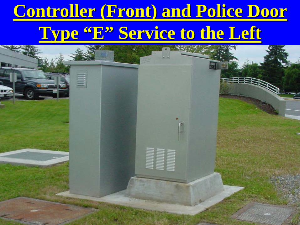
Controller (Front) and Police DoorType “E” Service to the Left

Controller Cabinet and Transformer

Good House Keeping Helps
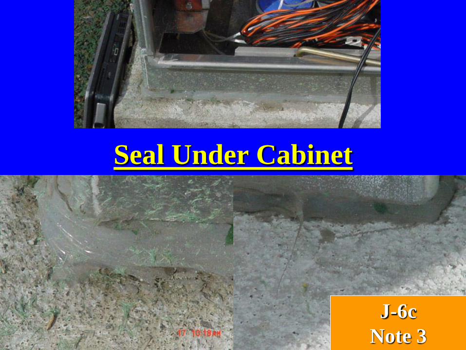
Seal Under Cabinet
J-6cNote 3


Temp Span System with Permanent
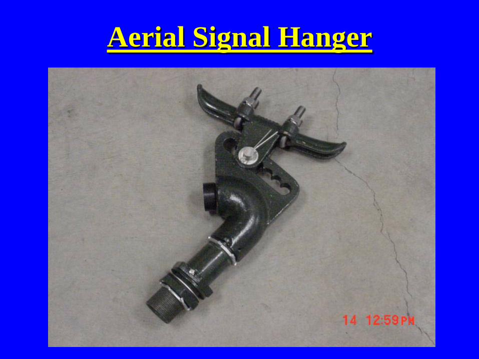
Aerial Signal Hanger

Signal Parts
Arm mount type M Top mount type D Pedestrian or Vehicle
End Cap Arm mount type L

Signal End Cap
The rubber washer needs to be inside the fixture between the
wall of the fixture and thesteel washer.
A bead of silicone sealant shall be applied around the perimeterof all top end cap openings prior
to installation of the end capassembly. 9-29.16(2)B

Ped Head E Mount (clamshell)J-6f
Left MountOpens Down Right Mount
Opens Down

Side of Pole Mounts
J-6f
Side mountswith terminalcompartments
Type B – Ped
Type K - Vehicle

5 Section Head and Sign
This sign is required withthe 5 section signal head

ADA Requires Wheel Chair Access
Good Bad

ADA Option

Ped Pole With “D” Mount
J-6f

Ped Pole With “C” MountJ-6f

Signal Bridge with Cameras
Data CamerasCCTV

Three Heads Three Types of Mounts M, L & LE
J-6g
M
L
LE

LED Red Arrow Is Failing
Red, Yellow and Green LED9-29.16(2)A

4 Section Head “M” Mount
8-20.3(14)B4 and 5 section stacksmount between secondand third display
9-29.16(2)DLouvered aluminumBack plates

Louvered Visors
9-29.16(2)C
Rt. Turn signal as viewed from through lane. Green arrow programmed out on right side.

Programmable Visors

Aiming Programmable Visors

Cone of VisionClearance above Rd. Clearance above Rd. Clearance above Rd.Min. Max. Min. Max. Min. Max.
16.5 Ft. 17.3 FT. 16.5 Ft. 16.9 FT. 16.5 Ft. 16.5 FT.
16.5 Ft. 19.1 FT. 16.5 Ft. 17.9 FT. 16.5 Ft. 16.8 FT.
16.5 Ft. 20.9 FT. 16.5 Ft. 19.7 FT. 16.5 Ft. 18.5 FT.
16.5 Ft. 21.9 FT. 16.5 Ft. 20.7 FT. 16.5 Ft. 19.6 FT.
Distance from stop bar3 section head 4 section head 5 section head
40-feet
45-feet
50-feet
53-150-feet
Link to Design Manual Pg. 571
5 Section cluster is the same height as 3 section head.All measurements are to bottom of signal head housing.

9-29.257
Pg. 9-199
Multi conductorsfor signal displaysshall be installed entirely through the mounting fitting to a pointa minimum of 1”inside the housing.8-20.3(8)
Install a spare 12 terminal strip
Terminal Can

ElectricalSafety Manual
Chapter 22
WAC 296-24-960
Maintain Ten Foot of Clearance from ALL Power Lines
NEC Table 225.61

Safety Manual• Chapter 22 Electrical Safety
– 22-2 High Voltage Lines• A) No work shall be performed around energized high
voltage electrical conductors.• B) Equipment shall be operated proximate to, under,
over, by, or near power lines only in accordance with the following:
– 1) For lines rated at 50 KV or below, minimum clearance between the lines and any part of the equipment or load shall be 10 feet.
– 2) For lines rated over 50 KV the minimum clearance between the lines and any part of the equipment or load shall be 10 feet plus .4-inch for each 1 KV over the 50 KV or twice the length of the line insulator but never less than 10 feet.

Design Manual – Signals page 850-12a
Design ManualPg. 586

Design Manual – Signals page 850-12a

Design Manual – Signals page 850-12a

Design Manual – Signals page 850-12b

Design Manual – Signals page 850-12b

Design Manual – Signals page 850-12b

Design Manual – Signals page 850-12c

Design Manual – Signals page 850-12c

Design Manual – Signals page 850-12d

Design Manual – Signals page 850-12d

Design Manual – Signals page 850-12d

Design Manual – Signals page 850-12e

Design Manual – Signals page 850-12e

Signal Standards
Standard Specifications• 8-20.3(14)e• 9-29.6 light and signal
standards• 9-29.6(1) steel light and
signal standards• 9-29.6(3) timber strain
poles
NEC Articles 250, 300.19,344, 352, 590, & 725

Standard Plan J-7a
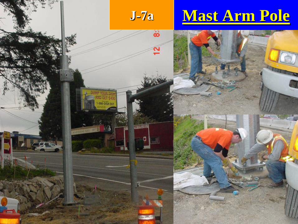

Make sure poles, mast arms and luminaire arms are in the
correct locations.
• Each part will have a tag on it. Make sure each part matches.

Anchor Bolt Nuts Tightening
8-20.3(4) All anchor bolt nuts must be tightened by the turn of the nut method. Minimum ¼ Max 1/3 turn past snug tight. Permanent marks shall be set on the base plate and the nuts.
6-03.3(32) Page 6-128 Assembling and Bolting6-03.3(33) Page 6-130 Bolted Connections (1)(Turn of the Nut)

Use the Proper ToolsNuts and bolts damaged with an improper tool will
have to be replaced.

Turning Anchor Bolt Nuts
• The Bridge group in Olympia suggest that it may require a hydraulic wrench or a multiplier wrench to be able to turn the nuts tight enough to meet the requirements of the Turn of the Nut tightening requirements. They indicate that the threads will actually start to stretch when we reach the specified tightness.