part 3: unified speech and audio codinged1.0}en.pdf · international standard iso/iec 23003-3:2012....
TRANSCRIPT

INTERNATIONAL STANDARD ISO/IEC 23003-3:2012TECHNICAL CORRIGENDUM 1
Published 2012-09-01
INTERNATIONAL ORGANIZATION FOR STANDARDIZATION МЕЖДУНАРОДНАЯ ОРГАНИЗАЦИЯ ПО СТАНДАРТИЗАЦИИ ORGANISATION INTERNATIONALE DE NORMALISATION
INTERNATIONAL ELECTROTECHNICAL COMMISSION МЕЖДУНАРОДНАЯ ЭЛЕКТРОТЕХНИЧЕСКАЯ КОМИССИЯ COMMISSION ÉLECTROTECHNIQUE INTERNATIONALE
Information technology — MPEG audio technologies —
Part 3: Unified speech and audio coding
TECHNICAL CORRIGENDUM 1
Technologies de l'information — Technologies audio MPEG —
Partie 3: Discours unifié et codage audio
RECTIFICATIF TECHNIQUE 1
Technical Corrigendum 1 to ISO/IEC 23003-3:2012 was prepared by Joint Technical Committee ISO/IEC JTC 1, Information technology, Subcommittee SC 29, Coding of audio, picture, multimedia and hypermedia information.
In 3.2 add at the end: v[] = {a} This expression indicates that all elements of the array v shall be set to the value a.
ICS 35.040 Ref. No. ISO/IEC 23003-3:2012/Cor.1:2012(E)
© ISO/IEC 2012 – All rights reserved
Published in Switzerland

ISO/IEC 23003-3:2012/Cor.1:2012(E)
2 © ISO/IEC 2012 – All rights reserved
In 4.1 replace the diagram:
with:

ISO/IEC 23003-3:2012/Cor.1:2012(E)
© ISO/IEC 2012 – All rights reserved 3
In 4.2. replace: The filterbank / block switching tool applies the inverse of the frequency mapping that was carried out in the encoder. An inverse modified discrete cosine transform (IMDCT) is used for the filterbank tool. The IMDCT can be configured to support 120, 128, 240, 256, 480, 512, 960 or 1024 spectral coefficients. with: The filterbank / block switching tool applies the inverse of the frequency mapping that was carried out in the encoder. An inverse modified discrete cosine transform (IMDCT) is used for the filterbank tool. The IMDCT can be configured to support 96, 128, 192, 256, 384, 512, 768, or 1024 spectral coefficients.
In 5.2 in Table 6, replace:
[…] case: ID_USAC_EXT UsacExtElementConfig(); break;
} } NOTE: UsacSingleChannelElementConfig(), UsacChannelPairElementConfig(), UsacLfeElement-Config() and UsacExtElementConfig() signaled at position elemIdx refer to the corresponding elements in UsacFrame() at the respective position elemIdx.
with
[…] case: ID_USAC_EXT UsacExtElementConfig(); break;
} } } NOTE: UsacSingleChannelElementConfig(), UsacChannelPairElementConfig(), UsacLfeElement-Config() and UsacExtElementConfig() signaled at position elemIdx refer to the corresponding elements in UsacFrame() at the respective position elemIdx.
In 5.3.1 in Table 17 replace:
[…] case: ID_USAC_EXT UsacExtElement(usacIndependencyFlag); break;
} }
with
[…] case: ID_USAC_EXT UsacExtElement(usacIndependencyFlag); break;
} } }

ISO/IEC 23003-3:2012/Cor.1:2012(E)
4 © ISO/IEC 2012 – All rights reserved
In 5.3.1 in Table 21 replace:
[…] if (usacExtElementUseDefaultLength) { usacExtElementPayloadLength = usacExtElementDefaultLength; } else { usacExtElementPayloadLength = escapedValue(8,16,0); } […]
with:
[…] if (usacExtElementUseDefaultLength) { usacExtElementPayloadLength = usacExtElementDefaultLength; } else { usacExtElementPayloadLength; 8 uimsbf if (usacExtElementPayloadLength==255) { valueAdd 16 uimsbf usacExtElementPayloadLength += valueAdd - 2; } } […]
In 5.3.2 in Table 23 replace:
[…] if (nrChannels == 2) { StereoCoreToolInfo(core_mode); } […]
with
[…] if (nrChannels == 2) { StereoCoreToolInfo(core_mode, indepFlag); } […]
In 5.3.2 in Table 24 replace:
Syntax No. of bits MnemonicStereoCoreToolInfo(core_mode) { if (core_mode[0] == 0 && core_mode[1] == 0) { tns_active; 1 uimsbf common_window; 1 uimsbf if (common_window) { ics_info(); common_max_sfb; 1 uimsbf if (common_max_sfb == 0) {

ISO/IEC 23003-3:2012/Cor.1:2012(E)
© ISO/IEC 2012 – All rights reserved 5
if (window_sequence == EIGHT_SHORT_SEQUENCE) { max_sfb1; 4 uimsbf } else { max_sfb1; 6 uimsbf } } else { max_sfb1 = max_sfb; } max_sfb_ste = max(max_sfb, max_sfb1); ms_mask_present; 2 uimsbf if ( ms_mask_present == 1 ) { for (g = 0; g < num_window_groups; g++) { for (sfb = 0; sfb < max_sfb; sfb++) { ms_used[g][sfb]; 1 uimsbf } } } if (ms_mask_present == 3) { cplx_pred_data(); } else { alpha_q_re[g][sfb] = 0; alpha_q_im[g][sfb] = 0; } } […]
with
Syntax No. of bits MnemonicStereoCoreToolInfo(core_mode, indepFlag) { if (core_mode[0] == 0 && core_mode[1] == 0) { tns_active; 1 uimsbf common_window; 1 uimsbf if (common_window) { ics_info(); common_max_sfb; 1 uimsbf if (common_max_sfb == 0) { if (window_sequence == EIGHT_SHORT_SEQUENCE) { max_sfb1; 4 uimsbf } else { max_sfb1; 6 uimsbf } } else { max_sfb1 = max_sfb; } max_sfb_ste = max(max_sfb, max_sfb1); ms_mask_present; 2 uimsbf if ( ms_mask_present == 1 ) { for (g = 0; g < num_window_groups; g++) { for (sfb = 0; sfb < max_sfb_ste; sfb++) { ms_used[g][sfb]; 1 uimsbf } } } if (ms_mask_present == 3) { cplx_pred_data(max_sfb_ste, indepFlag); } else {

ISO/IEC 23003-3:2012/Cor.1:2012(E)
6 © ISO/IEC 2012 – All rights reserved
alpha_q_re[][] = {0}; alpha_q_im[][] = {0}; } } […]
In 5.3.2 in Table 38 – Syntax of arith_data, replace: pki = arith_get_pk(c + esc_nb<<17) with: pki = arith_get_pk(c + (esc_nb<<17));
In 6.1.1.1 replace: usacSamplingFrequency Output sampling frequency of the decoder coded as unsigned integer value in
case usacSamplingFrequencyIndex equals zero.
with: usacSamplingFrequency Output sampling frequency of the decoder coded as unsigned integer value in
case usacSamplingFrequencyIndex is equal to the escape value.
In 6.1.1.1 add definition of bs_pvc by replacing: bs_interTes This flag signals the usage of the inter-TES tool in SBR.
with
bs_interTes This flag signals the usage of the inter-TES tool in SBR.
bs_pvc This flag signals the usage of the PVC tool in SBR.
In 6.1.1.2, replace:
bsStereoSbr This flag signals the usage of the stereo SBR in combination with MPEG Surround decoding.
with bsStereoSbr This flag signals the usage of the stereo SBR in combination with MPEG
Surround decoding. The value of bsStereoSbr is defined by stereoConfigIndex (see Table 72).

ISO/IEC 23003-3:2012/Cor.1:2012(E)
© ISO/IEC 2012 – All rights reserved 7
In 6.2.9.2.1 and in the headline of 6.2.9.2.3 replace:
scalefactor_data
with
scale_factor_data
In 6.2.9.2.4 replace fd_channelffeh_stream() with fd_channel_stream() In 6.2.9.4 replace: As explain in ISO/IEC 14496-3:2009, 4.5.2.3.4, the width of the scalefactor bands is built in imitation of the critical bands of the human auditory system. For that reason the number of scalefactor bands in a spectrum and their width depend on the transform length and the sampling frequency. Table 4.129 to Table 4.147, in ISO/IEC 14496-3:2009, 4.5.4, list the offset to the beginning of each scalefactor band on the transform lengths 1024 (960) and 128 (120) and on the sampling frequencies. For a transform length of 768 samples, the scale factor bands at equencysamplingfr3/4 are used. In case a shorter transform length (dependent on coreCoderFrameLength) is used, swb_offset_long_window and swb_offset_short_window are limited to the size of the transform length, and num_swb_long_window and num_swb_short_window is determined according to the following pseudo code with: As explained in ISO/IEC 14496-3:2009, 4.5.2.3.4, the width of the scalefactor bands is built in imitation of the critical bands of the human auditory system. For that reason the number of scalefactor bands in a spectrum and their width depend on the transform length and the sampling frequency. Table 4.129 to Table 4.147, in ISO/IEC 14496-3:2009, 4.5.4, list the offset to the beginning of each scalefactor band on the transform lengths 1024 and 128 and on the sampling frequencies (window length of 2048 and 256). For a transform length of 768 samples, the same 1024-based scalefactor band tables are used, but those corresponding to equencysamplingfr3/4 . In case a shorter transform length (dependent on coreCoderFrameLength) is used, swb_offset_long_window and swb_offset_short_window are limited to the size of the transform length, and num_swb_long_window and num_swb_short_window is determined according to the following pseudo code: In 6.2.13.2 replace the text block: bsOttBandsPhase defines the number of IPD parameter bands. If bsOttBandsPhasePresent==0, … with: bsOttBandsPhase defines the number of MPS parameter bands where phase coding is used. If
bsOttBandsPhasePresent==0, …

ISO/IEC 23003-3:2012/Cor.1:2012(E)
8 © ISO/IEC 2012 – All rights reserved
In 7.4.3 replace the pseudo code: /*Input variables*/ c /* old state context */ i /* Index of the 2-tuple to decode in the vector */ N /* Window Length */ /*Output value*/ c /*updated state context*/ c = arith_get_context(c,i,N) {
c = c>>4; if (i<N/4-1)
c = c + (q[0][i+1]<<12); c = (c&0xFFF0); if (i>0)
c = c + (q[1][i-1]); if (i > 3) {
if ((q[1][i-3] + q[1][i-2] + q[1][i-1]) < 5) return(c+0x10000);
} return (c);
} with: /*Input variables*/ c /* old state context */ i /* Index of the 2-tuple to decode in the vector */ N /* Window Length */ /*Output value*/ c /*updated state context*/ c = arith_get_context(c,i,N) {
c = (c & 0xFFFF)>>4; if (i<N/4-1)
c = c + (q[0][i+1]<<12); c = (c&0xFFF0); if (i>0)
c = c + (q[1][i-1]); if (i > 3) {
if ((q[1][i-3] + q[1][i-2] + q[1][i-1]) < 5) return(c+0x10000);
} return (c);
} Further in 7.4.3 replace the following pseudo code: /*input variables*/ offset /* number of decoded 2-tuples */ N /* Window length */ x_ac_dec /* vector of decoded spectal coefficients */ arith_finish(x_ace_dec,offset,N) {
for (i=offset ;i<N/4;i++) { x_ac_dec[2*i] = 0; x_ac_dec[2*i+1] = 0; q[1][i] = 1;
} } with: /*helper function*/ void arith_rewind_bitstream(offset); /* move the bitstream position indicator backward by ‘offset’ bits*/ /*input variables*/ offset /* number of decoded 2-tuples */ N /* Window length */ x_ac_dec /* vector of decoded spectal coefficients */

ISO/IEC 23003-3:2012/Cor.1:2012(E)
© ISO/IEC 2012 – All rights reserved 9
arith_finish(x_ace_dec,offset,N) {
arith_rewind_bitstream(14); for (i=offset ;i<N/4;i++) {
x_ac_dec[2*i] = 0; x_ac_dec[2*i+1] = 0; q[1][i] = 1;
} } In 7.4.3 in function arith_decode(), replace: value = (val<<1)… with: value = (value<<1)… Further in 7.4.3, replace: high = low +(range*cum_freq[symbol-1])>>14 – 1 with: high = low +((range*cum_freq[symbol-1])>>14) – 1; In 7.4.3 replace: …with the value c&esc_nb<<17 as input argument,… with …with the value c + (esc_nb<<17) as input argument,… In 7.4.3 replace: …the function get_pk()… with: …the function arith_get_pk()… Also in 7.4.3 replace: …If the condition (esc_nb>0 && m==0) is true … with: …If the condition (m==0 && lev>0) is true,…

ISO/IEC 23003-3:2012/Cor.1:2012(E)
10 © ISO/IEC 2012 – All rights reserved
Further down in the same subclause 7.4.3, replace:
arith_finish(x_ace_dec,offset,N)
with: arith_finish(x_ac_dec,offset,N) In 7.5.1 replace: The general description of the SBR tool can be found in ISO/IEC 14496-3:2009, 4.6.18. The above mentioned SBR tool shall be modified as described below. with: The general description of the SBR tool can be found in ISO/IEC 14496-3:2009, 4.6.18. The complex-exponential phase-shifting is outlined in ISO/IEC 14496-3:2009, 4.6.18.4.4. In USAC it shall be fixed to the default standard operation as defined in 4.6.18.4.1. The above mentioned SBR tool shall be modified as described below. In 7.5.1.1 add the following line: numTimeSlots number of SBR envelope time slots; is always 16. In 7.5.1.4 replace: Within one SBR frame there can be either one or two noise floors. The noise floor time borders are derived from the SBR envelope time border vector according to: … with: Independent of bs_pvc_mode within one SBR frame there can be either one or two noise floors. If bs_pvc_mode is zero, the noise floor time borders are derived from the SBR envelope time border vector according to: … In 7.5.1.5.2 replace the following text: If bs_pvc_mode in not zero, the SBR envelope time border vector of the current SBR frame, tE is calculated according to:
2 ,
1 ,
bs_num_envlots, numTimeS,
bs_num_envlots, numTimeSE bs_var_lenositionbs_noise_p'bs_var_len
bs_var_len'bs_var_lent
where
'bs_var_len is of the previous SBR frame. bs_var_len
otherwise 2
0ositionbs_noise_p if 1__ envnumbs
with: If bs_pvc_mode is not zero, the SBR envelope time border vector of the current SBR frame, tE is calculated according to:

ISO/IEC 23003-3:2012/Cor.1:2012(E)
© ISO/IEC 2012 – All rights reserved 11
is f the
1 if bs_noise_position 0
2 otherwiseEL
2 ,
1 ,
E
E
Llots, numTimeS,
Llots, numTimeSE bs_var_lenositionbs_noise_pvar_len'
bs_var_lenvar_len't
where
tsnumTimeSloL EE ]'[t'var_len'
EL'
and is the time border vector of the previous SBR frame and
is the number of envelopes of the previous frame respectively. Note that if bs_pvc_mode'==1 (PVC active
in previous frame), it follows that var_len previous SBR frame.
Et' Et
' bs_var_len o In the same subclause 7.5.1.5.2 replace: If bs_pvc_mode is not zero, the PVC SBR envelope time border vector of the current SBR frame, tEPVC, is calculated according to:
, 1
bs_noise_position , 2
first
EPVC
first
t , numTimeSlots bs_num_env
t , , numTimeSlots bs_num_envt
where
' , ' 0 and 0
0 , otherwise
first
bs_var_bord_1 bs_pvc_mode bs_pvc_modet
with: If bs_pvc_mode is not zero, the PVC SBR envelope time border vector of the current SBR frame, tEPVC, is calculated according to:
E
E
, 1
bs_noise_position , 2
first
EPVC
first
t , numTimeSlots L
t , , numTimeSlots L
t
where
, ' 0 and
0 , otherwisefirst
bs_pvc_mode bs_pvc_modet
0
var_len'
and and is the time border vector of the previous SBR frame
and is the number of envelopes of the previous frame respectively.
tsnumTimeSloL EE ]'[t'var_len'
EL'Et' Et
In the same subclause 7.5.1.5.2 replace: If bs_pvc_mode is not zero, the noise floor time borders vectors of the current SBR frame, tQ is calculated according to:
2 , )2(),1(),0(
1 , )1(),0(
sebs_num_noi
sebs_num_noi
EEE
EEQ ttt
ttt
where
1 if 0
2 otherwise
bs_noise_positionbs_num_noise

ISO/IEC 23003-3:2012/Cor.1:2012(E)
12 © ISO/IEC 2012 – All rights reserved
with: If bs_pvc_mode is not zero, the noise floor time borders vectors of the current SBR frame, tQ is calculated according to:
Q EL L
2 , )2(),1(),0(
1 , )1(),0(
Q
Q
L
L
EEE
EE
Q ttt
ttt
In 7.5.1.5.2 on page 96 replace equations as follows: else, bs_pvc_mode is not zero,
( 1, ( ))
( , ) ( , ), ,( , ( ))
iMapped x s i i
i
u i lm k t i t l m u
l i l
F rS
F r
for EEE Llltlli 0),1()()),((0 ttrnwhere
1 ,1 ( , ) : ( , ( )) ( 1, ( )), ( ) ( 1), 0( , )
0 ,otherwise
IndexMapped x E E Es
j k t i l j i l l t l l Li t
S F r F r t t
with: else, bs_pvc_mode is not zero,
( 1, ( ))
( , ) ( , ), ,( , ( ))
iMapped x s i i
i
u i lm k t i t l m u
l i l
F rS
F r
for EEPVCEPVC Llltlli 0),1()()),((0 ttrn
where
1 ,1 ( , ) : ( , ( )) ( 1, ( )), ( ) ( 1),0( , )
0 ,otherwise
IndexMapped x EPVC EPVC Es
j k t i l j i l l t l l Li t
S F r F r t t
In 7.5.1.5.2 replace the equation of MappedQ in case of pvc_mode is not zero as follows.Replace:
E
E E
( , ) , 0 ' ( )( , )
( , ) , (0) ( )
PreMapped x E
Mapped xPreMapped x E
m k t numTimeSlots t L' numTimeSlotsm k t
m k t t L
Q' tQ
Q t t
with:
E
E E
( , ) , 0 (0)( , )
( , ) , (0) (
PreMapped x
Mapped xPreMapped x E
m k t numTimeSlots tm k t
m k t t L
Q' tQ
Q t ) t

ISO/IEC 23003-3:2012/Cor.1:2012(E)
© ISO/IEC 2012 – All rights reserved 13
) t
In 7.5.1.5.2 replace the equation for in case of pvc_mode is not zero as follows. Replace: IndexMappedS
( , ), 0 ' ( )( , )
( , ) , (0) ( )
IndexPreMapped x E E
IndexMapped xIndexPreMapped x E E E
m k t numTimeSlots t L' numTimeSlotsm k t
m k t t L
S' tS
S t t
with:
( , ), 0 (0)( , )
( , ) , (0) (
IndexPreMapped x E
IndexMapped xIndexPreMapped x E E E
m k t numTimeSlots tm k t
m k t t L
S' tS
S t
In 7.5.1.5.4 replace equations as follows: else, bs_pvc_mode is not zero,
),(1
),(),(),(
tm
tmtmtm
Mapped
MappedOrigMappedM Q
QEQ
EEE LlltlMm 0),1()(,0, tt
with: else, bs_pvc_mode is not zero,
),(1
),(),(),(
tm
tmtmtm
Mapped
MappedOrigMappedM Q
QEQ
,
E
EPVCEPVC
Ll
ltl
Mm
0
),1()(
,0
tt
Further, replace: else, bs_pvc_mode is not zero,
),(1
),(),(),(
tm
tmtmtm
Mapped
dIndexMappeOrigMappedM Q
SES
EEE LlltlMm 0),1()(,0, tt
with: else, bs_pvc_mode is not zero,
),(1
),(),(),(
tm
tmtmtm
Mapped
dIndexMappeOrigMappedM Q
SES
,
E
EPVCEPVC
Ll
ltl
Mm
0
),1()(
,0
tt

ISO/IEC 23003-3:2012/Cor.1:2012(E)
14 © ISO/IEC 2012 – All rights reserved
In 7.5.2.2 replace:
03, , _ , , ;polyfit k x lowband lowEnv lowEnvSlope
with:
0
3
0
polyfit 3, , , , ;
( ) (3 ) ( )i
i
k x_lowband lowEnv polyCoeffs
lowEnvSlope k polyCoeffs i x_lowband k
In 7.5.5.2 replace:
10
0,010log ,0
6k
0lowEnv k k knumTimeSlots RATE
with:
10
0,010log ,0
( 3)k
0lowEnv k k knumTimeSlots RATE
In 7.5.6.3 replace
RATE
itRATEibXitRATEibX
tibE
HFGen
HFGen
tRATE
ti
lowlow
1* ),(),(
),(
with
RATE
itRATEibXitRATEibX
tibE
HFAdj
HFAdj
tRATE
ti
lowlow
1* ),(),(
),(
In 7.5.6.5 replace:
10
),(ˆ
10),(ˆtksgsgE
HFAdjHFGen
RATE
tttkE
with
10
),(ˆ
10),(ˆtksgsgE
tkE
In 7.9.3.2 replace: Depending on the window_sequence and window_shape element different transform windows are used. A combination of the window halves described as follows offers all possible window_sequences. Window lengths specified below are dependent on the core-coder frame length. Numbers are listed for coreCoderFrameLength of 1024 (960, 768).

ISO/IEC 23003-3:2012/Cor.1:2012(E)
© ISO/IEC 2012 – All rights reserved 15
with:
Depending on the window_sequence and window_shape element different transform windows are used. A combination of the window halves described as follows offers all possible window_sequences. Window lengths specified below are dependent on the core-coder frame length. Numbers are listed for coreCoderFrameLength of 1024 (768). Further below in 7.9.3.2 replace:
= kernel window alpha factor, = 4 for N =2048 (1920, 1536)
6 for N =256 (240, 192)
with:
= kernel window alpha factor, 4 for 2048 (1536)
6 for 256 (192)
N
N
In all of 7.9.3.2 remove the mentioning of 1920 and 240 sample window lengths.
In the rest of the document remove all further references to 960/120 based frame length or 1920/240 based window length and add reference to the 768/96 transform length (1536/192 window length) coding if appropriate and if not already present. Do so also in formulas, equations and figures. In 7.11.1, add to the end:
Unlike the delay introduced by MPEG Surround decoder as defined in ISO/IEC 23003-1:2007, 4.5, only High Quality decoding is supported in MPS212. It is noted that this implies that the delay of 5 QMF samples prior to the Nyquist analysis filterbanks shall not be inserted. In 7.11.2.3.4, replace:
If bsPhaseCoding == 1 and bsResidualCoding == 1, the matrix ,2l mR is defined as following:
with
If bsResidualCoding == 1, the matrix ,2l mR is defined as follows (where, if bsPhaseCoding == 1, the
transmitted ,l mIPD values are used, and where, if bsPhaseCoding == 0, the value is used for all parameter sets l and processing bands ):
0IPD m
In 7.11.2.3.4, add a sentence after the equation to calculate as follows: ,l mlinCLD
using
,
, 1010l mCLD
l mlinCLD
It is noted that resBands refers to the value of bsResidualBands, i.e. the number of MPS parameter bands where residual coding is used.
In 7.11.2.5 replace: For the 2-1-2 configuration, the frequency axis is divided into four different regions according to bsDecorrConfig = 0 and only one decorrelator is used, X = 0.
with:

ISO/IEC 23003-3:2012/Cor.1:2012(E)
16 © ISO/IEC 2012 – All rights reserved
For the 2-1-2 configuration, the frequency axis is divided into up to four different regions according to bsDecorrConfig but only one decorrelator is used, X = 0. At the end of 7.13 add a new subclause: 7.13.12 LPC initialization at decoder start-up In frames where the first decoded frame is LPD and the initial filter LPC0 is not transmitted within the bitstream, the LPD core decoder is reset as for a regular start-up. In particular, the ACELP decoder is initialized as described in 7.14.3. Additionally, the LSF vector corresponding to the LPC filter LPC0 is set to the value specified in Table COR1.2 before inverse LPC quantization. Right after inverse LPC quantization, the LSF vector corresponding to LPC0 is reset as follows:
,2
mean_lsf0
iLSFLSF
where mean_lsf is the mean LSF vector specified in Table COR1.2 and LSFi is the LSF vector corresponding to the LPC filter of frame i, i being determined as follows:
Table COR1.1 — Value of i for calculating LSF0
Condition Value of i
mod[0]<2 1
mod[0]=2 2
mod[0]=3 4
This operation corresponds to setting the LSF vector corresponding to LPC0 to average between the mean LSF vector and the nearest decoded LSF vector (which depends on the coding mode).
Table COR1.2 — Mean LSF vector for initialization
j mean_lsf(j)
1 394,21
2 754,45
3 1209,89
4 1580,47
5 1953,97
6 2325,80
7 2684,41
8 3038,39
9 3392,56
10 3744,71
11 4118,14
12 4483,09
13 4862,21
14 5219,69
15 5594,41
16 5945,73
ISO/IEC 23003-3:2012/Cor.1:2012(E)
© ISO/IEC 2012 – All rights reserved 17
Amend 7.16.3, list item 4, as follows: 4. Compute the inverse DCT-IV to the gain-scaled FAC data to obtain the equivalent time-domain samples.
- The FAC transform length, fac_length, is by default equal to coreCoderFrameLength/8 - For transitions with short blocks, this length is reduced to coreCoderFrameLength/16 In the case of transitions between ACELP and FD mode, a multiplicative factor of (2/fac_length) is applied to the output of the inverse DCT-IV.
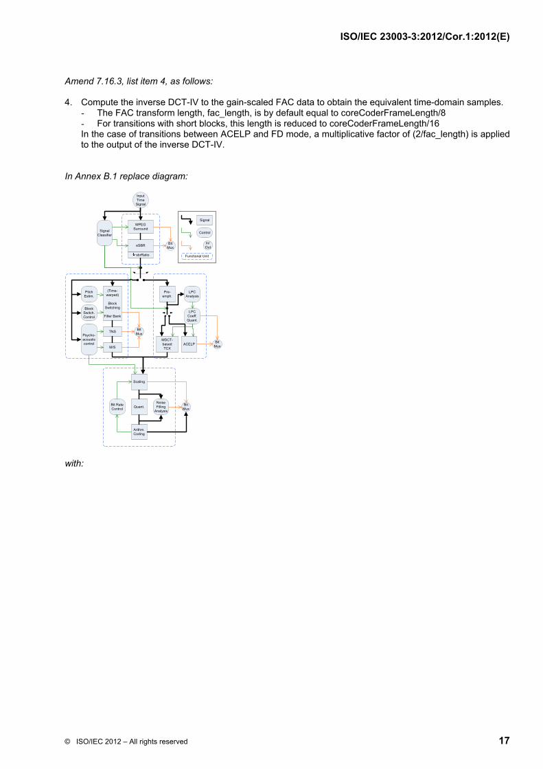
In Annex B.1 replace diagram:
MPEG Surround
eSBR
sbrRatio
Bit Mux
Scaling
Quant.
Arithm. Coding
Noise Filling
Analysis
Bit Rate Control
Bit Mux
(Time-warped)
Block Switching
Filter Bank
PitchEstim.
Block Switch.Control
Psycho-acousticcontrol
TNS
M/S
Bit Mux
Signal Classifier
Input Time
Signal
Pre-emph.
MDCT-based TCX
ACELP
LPC Analysis
Bit Mux
LPC Coeff. Quant.
Signal
Control
In/Out
Functional Unit
with:

ISO/IEC 23003-3:2012/Cor.1:2012(E)
18 © ISO/IEC 2012 – All rights reserved
In Annex B.16.3, Figure B.8 replace: Quantized LSFs with: Quantized weighted residual LSFs In Annex B.21 replace:
mpegsMuxMode = 2
with
bsResidualCoding = 1
Furthermore, throughout the whole document replace “ari_” with “arith_”