part 4 installation - *cimgas* · part 4 installation . ... change the pipe diameter at field) if...
TRANSCRIPT
MCAC-VTSM-2012-09 Installation
Installation 1
Part 4 Installation 1.Installation Introduction ..................................... 2
2.Units Installation ............................................... 17
2.1. Installation of Indoor Unit ....................................................... 17
2.2. Installation of Outdoor Unit .................................................... 17
3.Refrigerant Pipe Engineering .......................... 24
3.1. Refrigerant Pipe Processing ..................................................... 24
3.2. Air Tight Test ............................................................................ 34
3.3. Vacuum Drying ........................................................................ 36
3.4. Recharge of Refrigerant ........................................................... 38
4.Drainage Pipe Engineering .............................. 39
5.Duct Engineering .............................................. 44
6.Heat Insulation Engineering ............................ 47
7.Electrical Engineering ...................................... 50
8.Commissioning ................................................. 52
Par
t 4
Inst
alla
tion
MCAC-VTSM-2012-09 Installation
2 Installation
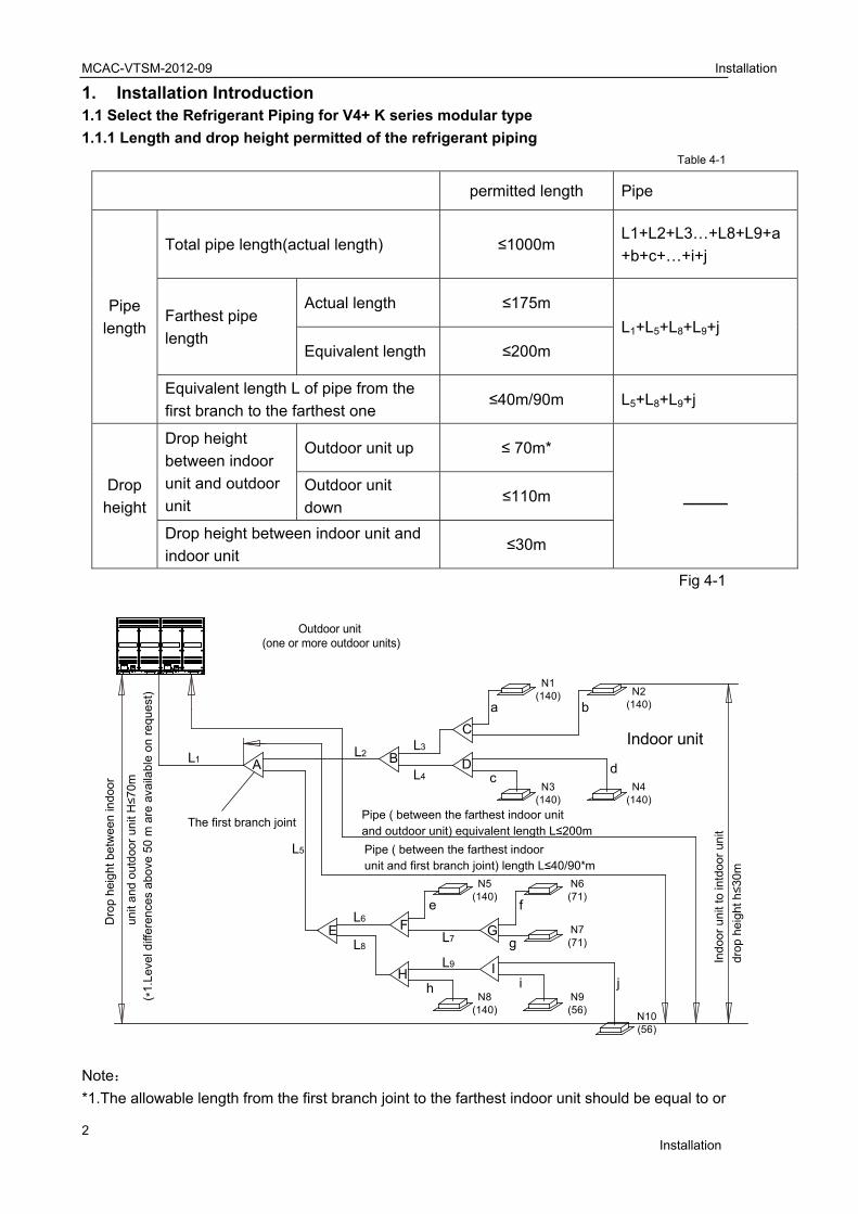
1. Installation Introduction 1.1 Select the Refrigerant Piping for V4+ K series modular type
1.1.1 Length and drop height permitted of the refrigerant piping Table 4-1
permitted length Pipe
Pipe
length
Total pipe length(actual length) ≤1000m L1+L2+L3…+L8+L9+a
+b+c+…+i+j
Farthest pipe
length
Actual length ≤175m
L1+L5+L8+L9+j
Equivalent length ≤200m
Equivalent length L of pipe from the
first branch to the farthest one ≤40m/90m L5+L8+L9+j
Drop
height
Drop height
between indoor
unit and outdoor
unit
Outdoor unit up ≤ 70m*
_____ Outdoor unit
down ≤110m
Drop height between indoor unit and
indoor unit ≤30m
Fig 4-1
Note:
*1.The allowable length from the first branch joint to the farthest indoor unit should be equal to or
N1(140)
N3(140)
N5(140)
N6(71)
N7(71)
N9(56)
N8(140)
N2(140)
N4(140)
N10(56)
A B D
E F G
H I
C
a b
c
e f
g
h i j
dL1
L2
L5
L7
L9
L8
L6
L3
L4
Outdoor unit(one or more outdoor units)
The first branch joint
Dro
phe
ight
betw
een
indo
or
un
ita
nd
out
doo
ru
nit
H≤7
0m
Pipe ( between the farthest indoorunit and first branch joint) length L≤40/90*m
Pipe ( between the farthest indoor unitand outdoor unit) equivalent length L≤200m
Indo
orun
itto
intd
oor
unit
drop
heig
hth≤3
0mIndoor unit
( *1.
Leve
ldiff
eren
ces
abov
e50
mar
eav
aila
ble
onre
ques
t)

MCAC-VTSM-2012-09 Installation
Installation 3
shorter than 40m. But the allowable length can extended to 90m, if the selection principle can
meets all the following conditions.
Condition Example
1.It is needed to increase all the pipe diameters of
the the main distribution pipe which between the
first and the last branch joint assembly. (Please
change the pipe diameter at field) If the pipe
diameter of the main slave pipe is the same as the
main pipe, then it is not needed to be increased.
L5+L8+L9+j≤90m
L2,L3,L4,L5,L6,L7,L8,L9
Need to increase the pipe diameter of the
distribution pipe
Increasing size as the following:
φ9.5→φ12.7 φ12.7→φ15.9 φ15.9→φ
19.1
φ19.1→φ22.2 φ22.2→φ25.4 φ25.4→φ
28.6
φ28.6→φ31.8 φ31.8→φ38.1 φ38.1→φ
41.3
φ41.3→φ44.5 φ44.5→φ54.0
2. When counting the total extended length,
the actual length of above distribution pipes
must be doubled.(Expect the main pipe and
the distribution pipes which no need to be
increased. )
L1+(L2+L3+L4+L5+L6+L7+L8+L9)×
2+a+b+c+d+e+f+g+h+i+j≤1000m
Reference Figure.4-1
3. The length from the indoor unit to the
nearest branch joint assembly ≤40m
a,b,c,...j≤40m(Pipe diameter requirements,
please refers to table .4-3)
Reference Figure.4-1
4. The distance difference between [the
outdoor unit to the farthest
indoor unit] and [the outdoor unit to the
nearest indoor unit] is
≤40m.
The farthest indoor unit
The nearest indoor unit
(L1+L5+L8+L9+j)-(L1+L2+L3+a)≤40m
Reference Figure.4-1
*2.Level difference above 50m are not supported by default but the project need to be approved
by the manufacture. (if the outdoor unit is above the indoor unit.)
3. Each branch equals to 0.5m pipe length. All branches must be purchased from Midea,
otherwise system is induced to malfunction.
4. All branches must be purchased from Midea, otherwise system is induced to malfunction.
N10
N10
N1
MCAC-VTSM-2012-09 Installation
4 Installation
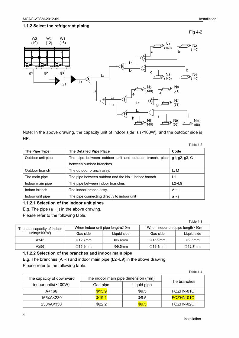
1.1.2 Select the refrigerant piping
Fig 4-2
Note: In the above drawing, the capacity unit of indoor side is (×100W), and the outdoor side is
HP. Table 4-2
The Pipe Type The Detailed Pipe Place Code
Outdoor unit pipe The pipe between outdoor unit and outdoor branch, pipe
between outdoor branches
g1, g2, g3, G1
Outdoor branch The outdoor branch assy. L, M
The main pipe The pipe between outdoor and the No.1 indoor branch L1
Indoor main pipe The pipe between indoor branches L2~L9
Indoor branch The indoor branch assy. A ~ I
Indoor unit pipe The pipe connecting directly to indoor unit a ~ j
1.1.2.1 Selection of the indoor unit pipes
E.g. The pipe (a ~ j) in the above drawing.
Please refer to the following table. Table 4-3
The total capacity of Indoor units(×100W)
When indoor unit pipe length≤10m When indoor unit pipe length>10m
Gas side Liquid side Gas side Liquid side
A≤45 Φ12.7mm Φ6.4mm Φ15.9mm Φ9.5mm
A≥56 Φ15.9mm Φ9.5mm Φ19.1mm Φ12.7mm
1.1.2.2 Selection of the branches and indoor main pipe
E.g. The branches (A ~I) and indoor main pipe (L2~L9) in the above drawing.
Please refer to the following table. Table 4-4
The capacity of downward
indoor units(×100W)
The indoor main pipe dimension (mm) The branches
Gas pipe Liquid pipe
A<166 Φ15.9 Φ9.5 FQZHN-01C
166≤A<230 Φ19.1 Φ9.5 FQZHN-01C
230≤A<330 Φ22.2 Φ9.5 FQZHN-02C
N1(140)
N3(140)
N5(140)
N6(71)
N7(71)
N9(56)
N8(140)
N2(140)
N4(140)
N10(56)
A
B
E F
H
G
I
C
D
L1
L2
L3
L4
L5
L6
L8
L9
L7
a b
c d
e f
g
i jh
W3(10)
W2(12)
W1(16)
M L
g1 g2 g3
G1

Thou
MCAC-VTSM
Installation
3
4
6
92
13
1.1.2.3 Sel
E.g. The m
Please refe
e capacity of utdoor units
8HP
10HP
12~14HP
16HP
18~22HP
24HP
26~32HP
34~48HP
50~64HP
Notice: If t
main pipe d
E.g. when
pipe length
While the to
No.1.1.2.2
should beΦ
1.1.2.4 Sel
E.g. The br
When there
When the m
Outdoor uquantity
2
M-2012-09
30≤A<460
60≤A<660
60≤A<920
20≤A<1350
50≤A<1800
1800≤A
ection of th
ain pipe (L1
er to the follo
WhenGas side
(mm)
Φ22.2
Φ22.2
Φ25.4
Φ28.6
Φ28.6
Φ28.6
Φ31.8
Φ38.1
Φ41.3
the total indo
dia. accordin
the total ca
h is more th
otal indoor u
table. Then
Φ44.5 and Φ
ection of th
ranch (L, M)
e is only sing
Model
8HP
10HP
12HP
14HP
16HP
multi outdoo
nit y
D
he main pip
) in the abo
owing table:
n total equivalLiquid side
(mm)
Φ9.53
Φ9.53
Φ12.7
Φ12.7
Φ15.9
Φ15.9
Φ19.1
Φ19.1
Φ22.2
oor units’ ca
ng to the big
pacity of 16
an 90m, the
units’ capaci
n, according
Φ22.2.
he branch (
) and outdoo
gle outdoor
or units are p
Drawing exam
Φ28.6
Φ28.6
Φ31.8
Φ38.1
Φ41.3
Φ44.5
pe (L1)
ve drawing
ent length<90e The indo
distrib
FQZHN
FQZHN
FQZHN
FQZHN
FQZHN
FQZHN
FQZHN
FQZHN
FQZHN
apacity is m
gger one.
HP+16HP+
e pipe dia. i
ty is 136kW
g to the prin
L, M) and th
or unit pipe (
unit, please
paralleled, p
mple
g81
0m oor No.1 butor
G
N-02C
N-02C
N-03C
N-03C
N-03C
N-03C
N-03C
N-04C
N-05C
ore than the
14HP paral
s Φ41.3 an
W, the pipe di
nciple of se
he outdoor
(g1, g2, g3,
e refer to the
Th
Φ25.4
Φ25.4
Φ31.8
Φ31.8
Φ31.8
lease refer t
Outdoor u
g1、g2: 8、10HP:Φ12~16HP:Φ
Φ12.7
Φ15.9
Φ19.1
Φ19.1
Φ22.2
Φ25.4
When tGas side
(mm) L
Φ22.2
Φ25.4
Φ28.6
Φ31.8
Φ31.8
Φ31.8
Φ38.1
Φ38.1
Φ44.5
e total outdo
leled outdoo
d Φ22.2 acc
ia. is Φ44.5
electing the
unit pipe (g
G1) in the a
e following ta
he outdoor unit
to the follow
unit pipe dia.(
Φ25.4/12.7;Φ31.8/Φ15.9
F
F
F
F
F
F
otal equivaleniquid side
(mm)
Φ12.7
Φ12.7
Φ15.9
Φ15.9
Φ19.1
Φ19.1
Φ22.2
Φ22.2
Φ25.4
oor units’, pl
or units is 46
cording to th
and Φ22.2 a
bigger, the
g1, g2, g3, G
above drawin
able:
t pipe dia. (mm
Φ
Φ
Φ
Φ
Φ
wing table:
(mm) O
9
LFQ
FQZHN-03C
FQZHN-03C
FQZHN-03C
FQZHN-04C
FQZHN-05C
FQZHN-05C
Tab
nt length≥90mThe indoor
branch
FQZHN-0
FQZHN-0
FQZHN-0
FQZHN-0
FQZHN-0
FQZHN-0
FQZHN-0
FQZHN-0
FQZHN-0
lease select
6HP, if the
he above ta
according to
main pipe
G1)
ng.
Tab
m)
Φ12.7
Φ12.7
Φ15.9
Φ15.9
Φ15.9
Tab
Outdoor bran
: QZHW-02N1
Installation
5
le 4-5
r No.1 h
02C
02C
03C
03C
03C
03C
04C
04C
05C
t the
total
able.
o the
dia.
le 4-6
le 4-7
nch
1C
n
MCAC-VTSM
6
3
4
Notice: All
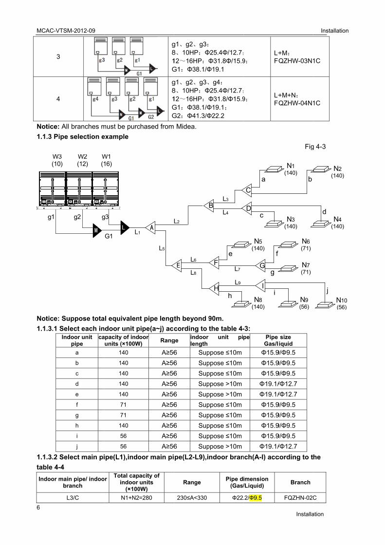
1.1.3 Pipe
Notice: Su
1.1.3.1 SelInd
1.1.3.2 Sel
table 4-4
Indoor mainbra
L
W3(10)
g1
M-2012-09
branches m
selection e
uppose tota
ect each indoor unit
pipe ca
a
b
c
d
e
f
g
h
i
j
ect main pi
n pipe/ indooanch
L3/C
W2(12)
W(1
M
g2 g
must be purc
example
al equivalen
door unit papacity of indunits (×100W
140
140
140
140
140
71
71
140
56
56
ipe(L1),indo
or Total cap
indoor (×100
N1+N2
L1
W116)
L
g3
G1
g81G
g81GG
chased from
nt pipe lengt
pipe(a~j) accoor
W) Rang
A≥56
A≥56
A≥56
A≥56
A≥56
A≥56
A≥56
A≥56
A≥56
A≥56
oor main pi
acity of units
0W)
=280
A1
L5
g1、g2、g3:8、10HP:Φ12~16HP:ΦG1:Φ38.1/Φ
g1、g2、g3、8、10HP:Φ12~16HP:ΦG1:Φ38.1/ΦG2:Φ41.3/Φ
Midea.
th beyond 9
cording to
ge indoor length
6 Sup
6 Sup
6 Sup
6 Sup
6 Sup
6 Sup
6 Sup
6 Sup
6 Sup
6 Sup
pe(L2-L9),i
Range
230≤A<330
E
L2
L6
L8
Φ25.4Φ/12.7;Φ31.8Φ/15.9Φ19.1
g4: Φ25.4Φ/12.7;Φ31.8/Φ15.9Φ19.1; Φ22.2
90m.
the table 4-unit pi
ppose ≤10m
ppose ≤10m
ppose ≤10m
ppose >10m
ppose >10m
ppose ≤10m
ppose ≤10m
ppose ≤10m
ppose ≤10m
ppose >10m
ndoor bran
Pipe d(Gas/
Ф22
B
F
H
L3
L4
L9
L7
e
h
9;
L+FQ
9;
L+FQ
-3:
pe Pipe Gas/l
Φ15.9
Φ15.9
Φ15.9
Φ19.1/
Φ19.1/
Φ15.9
Φ15.9
Φ15.9
Φ15.9
Φ19.1/
nch(A-I) acc
imension /Liquid)
.2/Ф9.5
N5(140)
N8(140)
G
I
C
D
a
c
f
g
i
Installa
+M: QZHW-03N1
+M+N: QZHW-04N1
Fig
size iquid
9/Φ9.5
9/Φ9.5
9/Φ9.5
/Φ12.7
/Φ12.7
9/Φ9.5
9/Φ9.5
9/Φ9.5
9/Φ9.5
/Φ12.7
cording to t
Branch
FQZHN-02C
N1(140)
N3(140)
N6(71)
N7(71)
N9(56)
b
Installation
ation
1C
1C
g 4-3
he
C
N2(140)
N4(140)
N10(56)
d
j
n
MCAC-VTSM-2012-09 Installation
Installation 7
OD:1
2.7
ID:9
.5
ID:9
.5
ID:6
.4
OD:9
.5
ID:6
.4
OD:9
.5
ID:9
.5
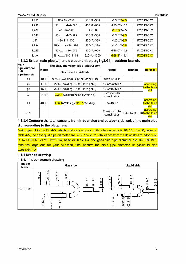
L4/D N3+ N4=280 230≤A<330 Ф22.2/Ф9.5 FQZHN-02C
L2/B N1+……+N4=560 460≤A<660 Ф28.6/Ф15.9 FQZHN-03C
L7/G N6+N7=142 A<166 Ф15.9/Ф9.5 FQZHN-01C
L6/F N5+……+N7=282 230≤A<330 Ф22.2/Ф9.5 FQZHN-02C
L9/I N9+N10=136 230≤A<330 Ф22.2/Ф9.5 FQZHN-02C
L8/H N8+……+N10=276 230≤A<330 Ф22.2/Ф9.5 FQZHN-02C
L5/E N5+……N10=558 460≤A<660 Ф28.6/Ф15.9 FQZHN-03C
L1/A N1+……N10=1118 920≤A<1350 Ф38.1/Ф19.1 FQZHN-04C
1.1.3.3 Select main pipe(L1) and outdoor unit pipe(g1-g3,G1),outdoor branch,
Main pipe/outdoor unit pipe/branch
Model
The Max. equivalent pipe length≥ 90m
Range Branch Refer to Gas Side/ Liquid Side
g1 10HP Φ25.4 (Welding)/ Φ12.7(Flaring Nut) 8≤W3≤10HP /
according to the table
4-7
g2 14HP Φ31.8(Welding)/15.9 (Flaring Nut) 12≤W2≤16HP /
g3 16HP Φ31.8(Welding)/15.9 (Flaring Nut) 12≤W1≤16HP /
G1 24HP Φ38.1Welding)/ Φ19.1(Welding) Two modular combination
/
L1 40HP Φ38.1(Welding)/ Φ19.1(Welding) 34-48HP / according
to the table 4-5
L+M / / Three modular combination
FQZHW-03N1C according
to the table 4-7
1.1.3.4 Compare the total capacity from indoor side and outdoor side, select the main pipe
dia. according to the bigger one.
Main pipe L1 in the Fig.4-3, which upstream outdoor units total capacity is 10+12+16=38, base on
table.4-5, the gas/liquid pipe diameter are Φ38.1/Φ22.2, total capacity of the downstream indoor unit
is 140×6+56×2+71×2=1094, base on table.4-4, the gas/liquid pipe diameter are Φ38.1/Φ19.1,
take the large one for your selection, final confirm the main pipe diameter is: gas/liquid pipe
Φ38.1/Φ22.2.
1.1.4 Branch drawing
1.1.4.1 Indoor branch drawing Indoor branch
Gas side Liquid side
FQZHN-01C
ID:12.7
(ID:15.9)
OD:19.1
ID:19.1
OD:19.1
ID:19.1
ID:15.9ID:12.7
(ID:15.9)
OD:19.1

MCAC-VTSM-2012-09 Installation
8 Installation
FQZHN-02C
FQZHN-03C
FQZHN-04C
FQZHN-05C
ID:15.9
(ID:19.1)
OD:22.2
ID:22.2
OD:22.2
ID:22.2
ID:25.4ID:15.9
(ID:19.1)
OD:22.2
ID:12.7
ID:28.6
ID:31.8
OD:28.6
ID:28.6
ID:19.1
ID:22.2
OD:28.6
ID:19.1
ID:22.2
OD:28.6
ID:15.9
ID:1
5.9
OD:1
5.9
ID:1
9.1
(ID:
12.7
)
OD:1
5.9
ID:9
.5
ID:1
5.9
(ID:
12.7
)
OD:1
5.9
ID:9
.5
ID:6
.4
ID:19.1
ID:22.2
ID:28.6
OD:34.9
ID:34.9
OD:34.9
ID:38.1ID
:22.2
ID:28.6
OD:34.9
ID:34.9
ID:12.7
(ID:15.9)
OD:19.1
ID:19.1
OD:19.1
ID:19.1
ID:22.2
ID:12.7
(ID:15.9)
OD:19.1
ID:9.5
ID:1
5.9
(ID:
19.1
)
OD:2
2.2
ID:2
2.2
OD:22.2
ID:2
2.2
ID:2
5.4
ID:1
5.9
(ID:
19.1
)
OD:2
2.2
ID:1
2.7
OD:1
2.7
ID:6
.4
ID:9
.5
OD:1
2.7
OD:1
2.7
ID:1
2.7
ID:1
2.7
ID:6
.4
ID:9
.5
MCAC-VTSM
Installation
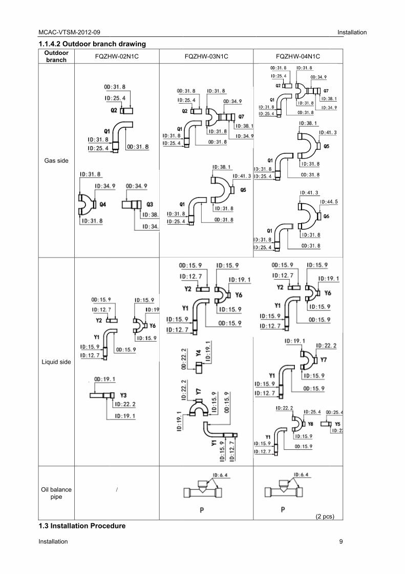
1.1.4.2 OutOutdoor branch
Gas side
Liquid side
Oil balance pipe
1.3 Installa
M-2012-09
tdoor branc
FQZH
ation Proce
ch drawing
HW-02N1C
/
edure
FQZHW-03N
N1C
FQZHW
W-04N1C
(2 pc
Installation
9
s)
n
MCAC-VTSM-2012-09 Installation
10 Installation
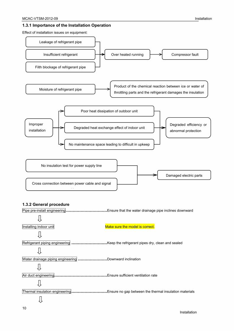
1.3.1 Importance of the Installation Operation
Effect of installation issues on equipment:
1.3.2 General procedure
Pipe pre-install engineering ............................... Ensure that the water drainage pipe inclines downward
Installing indoor unit Make sure the model is correct.
Refrigerant piping engineering ........................... Keep the refrigerant pipes dry, clean and sealed
Water drainage piping engineering ...................... Downward inclination
Air duct engineering........................................ Ensure sufficient ventilation rate
Thermal insulation engineering ........................... Ensure no gap between the thermal insulation materials
Insufficient refrigerant Over heated running Compressor fault
Filth blockage of refrigerant pipe
Leakage of refrigerant pipe
Product of the chemical reaction between ice or water of
throttling parts and the refrigerant damages the insulation Moisture of refrigerant pipe
Degraded efficiency or
abnormal protection
Improper
installation Degraded heat exchange effect of indoor unit
No maintenance space leading to difficult in upkeep
Poor heat dissipation of outdoor unit
No insulation test for power supply line
Damaged electric parts
Cross connection between power cable and signal
bl
MCAC-VTSM-2012-09 Installation
Installation 11
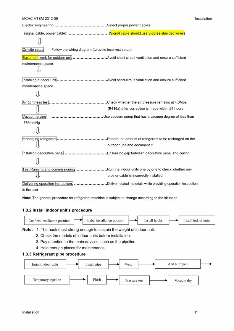
Electric engineering ........................................ Select proper power cables
(signal cable, power cable) ............................. (Signal cable should use 3-cores shielded wires)
On-site setup Follow the wiring diagram (to avoid incorrect setup)
Basement work for outdoor unit .......................... Avoid short-circuit ventilation and ensure sufficient
maintenance space
Installing outdoor unit ...................................... Avoid short-circuit ventilation and ensure sufficient
maintenance space
Air tightness test ............................................ Check whether the air pressure remains at 4.0Mpa
(R410a) after correction is made within 24 hours
Vacuum drying ....................................... Use vacuum pump that has a vacuum degree of less than
-775mmHg
recharging refrigerant ...................................... Record the amount of refrigerant to be recharged on the
outdoor unit and document it
Installing decorative panel ................................ Ensure no gap between decorative panel and ceiling
Test Running and commissioning ........................ Run the indoor units one by one to check whether any
pipe or cable is incorrectly installed
Delivering operation instructions ......................... Deliver related materials while providing operation instruction
to the user
Note: The general procedure for refrigerant machine is subject to change according to the situation
1.3.2 Install indoor unit’s procedure
Note: 1. The hook must strong enough to sustain the weight of indoor unit.
2. Check the models of indoor units before installation.
3. Pay attention to the main devices, such as the pipeline.
4. Hold enough places for maintenance.
1.3.3 Refrigerant pipe procedure
Confirm installation position Label installation position Install indoor units Install hooks
Install indoor units Install pipe Weld Add Nitrogen
Temporary pipeline Flush Pressure test Vacuum dry
MCAC-VTSM-2012-09 Installation
12 Installation
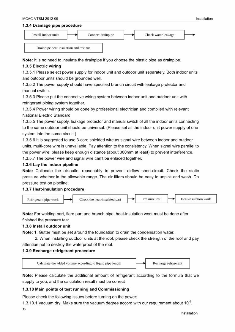
1.3.4 Drainage pipe procedure
Note: It is no need to insulate the drainpipe if you choose the plastic pipe as drainpipe.
1.3.5 Electric wiring
1.3.5.1 Please select power supply for indoor unit and outdoor unit separately. Both indoor units
and outdoor units should be grounded well.
1.3.5.2 The power supply should have specified branch circuit with leakage protector and
manual switch.
1.3.5.3 Please put the connective wiring system between indoor unit and outdoor unit with
refrigerant piping system together.
1.3.5.4 Power wiring should be done by professional electrician and complied with relevant
National Electric Standard.
1.3.5.5 The power supply, leakage protector and manual switch of all the indoor units connecting
to the same outdoor unit should be universal. (Please set all the indoor unit power supply of one
system into the same circuit.)
1.3.5.6 It is suggested to use 3-core shielded wire as signal wire between indoor and outdoor
units, multi-core wire is unavailable. Pay attention to the consistency. When signal wire parallel to
the power wire, please keep enough distance (about 300mm at least) to prevent interference.
1.3.5.7 The power wire and signal wire can’t be enlaced together.
1.3.6 Lay the indoor pipeline
Note: Collocate the air-outlet reasonably to prevent airflow short-circuit. Check the static
pressure whether in the allowable range. The air filters should be easy to unpick and wash. Do
pressure test on pipeline.
1.3.7 Heat-insulation procedure
Note: For welding part, flare part and branch pipe, heat-insulation work must be done after
finished the pressure test.
1.3.8 Install outdoor unit
Note: 1. Gutter must be set around the foundation to drain the condensation water.
2. When installing outdoor units at the roof, please check the strength of the roof and pay
attention not to destroy the waterproof of the roof.
1.3.9 Recharge refrigerant procedure
Note: Please calculate the additional amount of refrigerant according to the formula that we
supply to you, and the calculation result must be correct
1.3.10 Main points of test running and Commissioning
Please check the following issues before turning on the power:
1.3.10.1 Vacuum dry: Make sure the vacuum degree accord with our requirement about 10-5.
Drainpipe heat-insulation and test-run
Install indoor units Connect drainpipe Check water leakage
Refrigerant pipe work Check the heat-insulated part Pressure test Heat-insulation work
Calculate the added volume according to liquid pipe length Recharge refrigerant

MCAC-VTSM-2012-09 Installation
Installation 13
1.3.10.2 Wiring: Includes the power wiring and communication wiring; Recheck the connection
according to our corresponding wire diagrams. Especially, please remember our communication
wire is polar; it means you must connect the communication wire correspondingly to the terminal
block.
1.3.10.3 Additional charge of refrigerant: Recheck the calculation formula and recalculate the
total recharge volume according to our supplied formula.
1.3.10.4 Open the stop-valve of gas and liquid pipe with Allen key; Check leakage of stop-valve
with soap water. Please confirm whether the outdoor unit has been connected to the power for
12hr before start test running.
Test running: Turn on all of the indoor units with cooling mode and set the temperature in
17degree with high fan speed first, after the system operated, test following operation
parameters of the system, including indoor units and outdoor units parameters.
1.4 Installation Preparation
1.4.1 Installation tools and instruments
All the necessary tools should be available, and their models and specifications should meet the
installation and technical requirements. The instruments and meters should be tested or verified,
and their scales and accuracy should meet the requirements. The common tools for installing
refrigerant machine are listed below.
No. Name Specification/Model No. Name Specification/Model
1 Pipe cutter 15 Electronic scale
2 Steel saw 16 Stop
3 Pipe bender Spring, mechanic 17 Thermometer
4 Pipe expander Depend on the pipe diameter specification
18 Meter rule
5 Flaring tool Depend on the pipe diameter specification
19 Screw driver “-”, “+”
6 Brazing welder Depend on the nozzle size
Adjustable spanner
7 Scraper 21 Resistance
tester
8 File/Rasp 22 Electro probe
9 Injection tube 23 Multimeter
10 Double-ended pressure gauge
4.0MPa 24 Pressure reducing valve
11 Pressure gauge 1.5MPa, 4.0MPa 25 Wire pliers
12 Vacuum gauge -756mmHg 26 Clamping pliers
13 Vacuum pump At least 4 liters/second 27 Hexagon ring spanner
14 Horizontal rule 28 Torque wrench
In addition, tools such as electric welder, cutter, A-shape ladder, electric drill, folding machine,
forming machine, nitrogen cylinder are also generally used during the installation.
1.4.2 Audit of construction drawings
Before the engineering installation, read carefully the related drawings to understand the design
intention, audit the drawings, and then work out a detailed engineering organization plan.
1. Make sure that the pipe diameters and branch pipe models meet the technical specifications.
2. Ratio of slope, drainage mode and thermal insulation of condensate water.
3. Making of air duct and air opening, and air ventilation organization.
4. Configuration specifications, model and control mode of power cables.
5. Making, total length and control mode of control cable.
MCAC-VTSM
14
The engine
constructio
department
1.4.3. Cons
Constructio
that guide t
constructio
constructio
results.
The constru
and time co
thus to ens
1.4.4. Train
Establish s
managers,
Establish a
after-shift im
1.4.5. Coor
Ensure smo
civil work, e
best to lay
together at
1. Ensure t
pipes.
2. Ensure t
1.4.6. Pipe
1.4.6.1. Op
Raise requ
quantity of
1.4.6.2. Pip
1. The pipe
1/100).
2. The diam
thermal ins
pipe in two
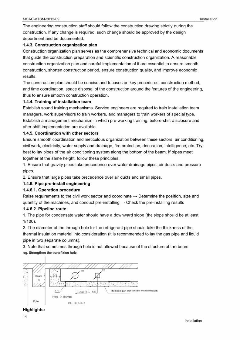
3. Note tha
Highlights
M-2012-09
eering const
n. If any cha
t and be doc
struction o
on organizat
the construc
n organizati
n, shorten c
uction plan s
oordination,
sure smooth
ning of inst
ound trainin
work superv
a manageme
mplementat
rdination w
ooth coordin
electricity, w
pipes of the
the same h
hat gravity p
hat large pip
e pre-install
peration pro
irements to
the machine
peline route
e for conden
meter of the
sulation mate
separate co
at sometimes
s:
ruction staff
ange is requ
cumented.
rganization
tion plan ser
ction prepara
on plan and
construction
should be co
space dispo
constructio
tallation tea
ng mechanis
visors to tra
ent mechani
ion are avai
with other se
nation and m
water supply
e air conditio
eight, follow
pipes take p
pes take pre
engineerin
ocedure
the civil wor
es, and cond
e
sate water s
through hol
erial into con
olumns).
s through ho
f should follo
uired, such c
n plan
rves as the c
ation and sc
d careful imp
period, ens
oncise and f
osal of the c
n operation.
am
sms. Service
in workers, a
sm in which
lable.
ectors
meticulous o
and drainag
ning system
w these princ
recedence o
ecedence ov
ng
rk sector and
duct pre-inst
should have
e for the ref
nsideration (
ole is not allo
ow the const
change shou
comprehens
cientific cons
plementation
ure construc
focuses on k
construction
.
e engineers
and manage
h pre-working
rganization
ge, fire prote
m along the b
ciples:
over water d
ver air ducts
d coordinate
talling → Ch
e a downwar
frigerant pipe
(it is recomm
owed becau
truction draw
uld be appro
sive technica
struction org
n of it are es
ction quality
key procedu
around the f
are required
ers to train w
g training, b
between the
ection, deco
bottom of th
drainage pip
s and small p
e → Determ
heck the pre
rd slope (the
e should tak
mended to la
use of the str
wing strictly
oved by the d
al and econo
anization. A
sential to en
, and improv
ures, constru
features of t
d to train ins
workers of s
efore-shift d
ese sectors:
ration, intelli
e beam. If p
pes, air ducts
pipes.
ine the posi
e-installing re
e slope shou
ke the thickn
ay the gas p
ructure of th
Installa
during the
design
omic docum
A reasonable
nsure smoot
ve economic
uction metho
the engineer
stallation tea
special type.
disclosure an
air conditio
igence, etc.
pipes meet
s and press
ition, size an
esults
uld be at lea
ness of the
pipe and liqu
he beam.
Installation
ation
ents
e
th
c
od,
ring,
am
nd
ning,
Try
ure
nd
st
id
n

MCAC-VTSM-2012-09 Installation
Installation 15
1) When selecting the parts to be pre-installed, ensure that the weight of the accessories is also
calculated.
2) In a situation where metal parts to be pre-installed is not allowed, use expansion bolts while
ensuring sufficient load-bearing capacity.
Caution: The above figure is for reference only. It is not recommended to dig holes on either the
beam or the shear wall. If such operation is indeed needed, please consult the property owner
(or manager) and the civil work sector, and get written approval from the competent authority.
1.4.7 Warning
(1) Be sure only trained and qualified service personnel to install, repair or service the
equipment.
Improper installation, repair, and maintenance may result in electric shocks, short-circuit, leaks,
fire or other damage to the equipment.
(2) Install according to this installation instructions strictly.
If installation is defective, it will cause water leakage, electrical shock fire.
(3) When installing the unit in a small room, take measures against to keep refrigerant
concentration from exceeding allowable safety limits in the event of refrigerant leakage.
Contact the place of purchase for more information. Excessive refrigerant in a closed ambient
can lead to oxygen deficiency.
(4) Use the attached accessories parts and specified parts for installation. otherwise, it will cause
the set to fall, water leakage, electrical shock fire.
(5) Install at a strong and firm location which is able to withstand the set' s weight.
If the strength is not enough or installation is not properly done, the set will drop to cause injury.
(6) The appliance must be installed 2.5m above floor.
(7) The appliance shall not be installed in the laundry.
(8) Before obtaining access to terminals, all supply circuits must be disconnected.
(9) The appliance must be positioned so that the plug is accessible.
(10) The enclosure of the appliance shall be marked by word, or by symbols, with the direction of
the fluid flow.
(11) For electrical work, follow the local national wiring standard, regulation and installation
instruction. An independent circuit and single outlet must be used.
If electrical circuit capacity is not enough or defect in electrical work, it will cause electrical shock
fire.
(12) Use the specified cable and connect tightly and clamp the cable so that no external force will
be acted on the terminal.
If connection or fixing is not perfect, it will cause heat-up or fire at the connection.
(13) Wiring routing must be properly arranged so that control board cover is fixed properly.
If control board cover is not fixed perfectly, it will cause heat-up at connection point of terminal,
fire or electrical shock.
(14) If the supply cord is damaged, it must be replaced by the manufacture or its service agent or
similarly qualified person in order to avoid a hazard.
(15) An all-pole disconnection switch having a contract separation of at least 3mm in poles
should be connected in fixed wiring.
(16) When carrying out piping connection, take care not to let air substances go into refrigeration
cycle.
Otherwise, it will cause lower capacity, abnormal high pressure in the refrigeration cycle,
explosion and injury.

MCAC-VTSM-2012-09 Installation
16 Installation
(17) Do not modify the length of the power supply cord or use of extension cord, and do not
share the single outlet with other electrical appliances.
Otherwise, it will cause fire or electrical shock.
(18) Carry out the specified installation work after taking into account strong winds, typhoons or
earthquakes.
Improper installation work may result in the equipment falling and causing accidents.
Remark: Failure to observe a warning may result in death.
1.4.8 Caution
(1) Ground the air conditioner.
Do not connect the ground wire to gas or water pipes, lightning rod or a telephone ground wire.
Incomplete grounding may result in electric shocks.
(2) Be sure to install an earth leakage breaker.
Failure to install an earth leakage breaker may result in electric shocks.
(3) Connect the outdoor unit wires, and then connect the indoor unit wires.
You are not allowed to connect the air conditioner with the power source until wiring and piping
the air conditioner is done.
(4) While following the instructions in this installation manual, install drain piping in order to
ensure proper drainage and insulate piping in order to prevent condensation.
Improper drain piping may result in water leakage and property damage.
(5) Install the indoor and outdoor units, power supply wiring and connecting wires at least 1
meter away from televisions or radios in order to prevent image interference or noise.
Depending on the radio waves, a distance of 1 meter may not be sufficient enough to eliminate
the noise.
(6) The appliance is not intended for use by young children or infirm persons without supervision.
Young children should be supervised to ensure that they do not play with the appliance.
(7) Don't install the air conditioner in the following locations:
There is petrolatum existing.
There is salty air surrounding (near the coast).
There is caustic gas (the sulfide, for example) existing in the air (near a hot spring).
The Volt vibrates violently (in the factories).
In buses or cabinets.
In kitchen where it is full of oil gas.
There is strong electromagnetic wave existing.
There are inflammable materials or gas.
There is acid or alkaline liquid evaporating.
Other special conditions.
(8) The insulation of the metal parts of the building and the air conditioner should comply with the
regulation of National Electric Standard.
Remark: Failure to observe a caution may result in injury or damage to the equipment.
MCAC-VTSM-2012-09 Installation
Installation 17
2. Units Installation 2.1. Installation of Indoor Unit
2.1.1 Installation procedure
Determine the installation position → Scribing and locating → Installing suspension road → Installing the
indoor unit
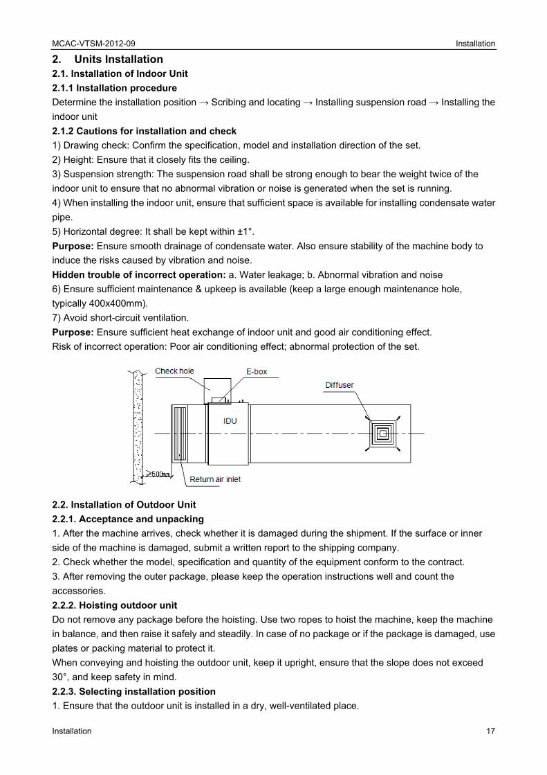
2.1.2 Cautions for installation and check
1) Drawing check: Confirm the specification, model and installation direction of the set.
2) Height: Ensure that it closely fits the ceiling.
3) Suspension strength: The suspension road shall be strong enough to bear the weight twice of the
indoor unit to ensure that no abnormal vibration or noise is generated when the set is running.
4) When installing the indoor unit, ensure that sufficient space is available for installing condensate water
pipe.
5) Horizontal degree: It shall be kept within ±1°.
Purpose: Ensure smooth drainage of condensate water. Also ensure stability of the machine body to
induce the risks caused by vibration and noise.
Hidden trouble of incorrect operation: a. Water leakage; b. Abnormal vibration and noise
6) Ensure sufficient maintenance & upkeep is available (keep a large enough maintenance hole,
typically 400x400mm).
7) Avoid short-circuit ventilation.
Purpose: Ensure sufficient heat exchange of indoor unit and good air conditioning effect.
Risk of incorrect operation: Poor air conditioning effect; abnormal protection of the set.
2.2. Installation of Outdoor Unit
2.2.1. Acceptance and unpacking
1. After the machine arrives, check whether it is damaged during the shipment. If the surface or inner
side of the machine is damaged, submit a written report to the shipping company.
2. Check whether the model, specification and quantity of the equipment conform to the contract.
3. After removing the outer package, please keep the operation instructions well and count the
accessories.
2.2.2. Hoisting outdoor unit
Do not remove any package before the hoisting. Use two ropes to hoist the machine, keep the machine
in balance, and then raise it safely and steadily. In case of no package or if the package is damaged, use
plates or packing material to protect it.
When conveying and hoisting the outdoor unit, keep it upright, ensure that the slope does not exceed
30°, and keep safety in mind.
2.2.3. Selecting installation position
1. Ensure that the outdoor unit is installed in a dry, well-ventilated place.

MCAC-VTSM-2012-09 Installation
18 Installation
2. Ensure that the noise and exhaust ventilation of the outdoor unit do not affect the neighbors of the
property owner or the surrounding ventilation.
3. Ensure that the outdoor unit is installed in a well-ventilated place that is possibly closest to the indoor
unit.
4. Ensure that the outdoor unit is installed in a cool place without direct sunshine exposure or direct
radiation of a high-temperature heat source.
5. Do not install the outdoor unit in a dirty or severely polluted place, so as to avoid blockage of the heat
exchanger in the outdoor unit.
6. Do not install the outdoor unit in a place with oil pollution, salt or high content of harmful gases such as
sulfurous gas.
2.2.4. Base for outdoor unit
1. A solid, correct base can:
1) Avoid the outdoor unit from sinking.
2) Avoid the abnormal noise generated due to base.
2. Base types
1) Steel structure base
2) Concrete base (see the figure below for the general making method)
Remark:
The key points to make basement:
1) The master unit’s basement must be made on the solid concrete ground. Refer to the structure
diagram to make concrete basement in detail, or make after field measurements.
2) In order to ensure every point can contact equality, the basement should be on completely level.
3) If the basement is placed on the roofing, the detritus layer isn’t needed, but the concrete surface must
be flat. The standard concrete mixture ratio is cement 1/ sand 2/ carpolite 4, and adds Φ10 strengthen
reinforcing steel bar, the surface of the cement and sand plasm must be flat, border of the basement
must be chamfer angle.
4) In order to drain off the seeper around the equipment, a discharge ditch must be setup around the
basement.
5) Please check the affordability of the roofing to ensure the load capacity.
2.2.5. Installation highlights for outdoor unit
1. Install vibration isolator or isolating pad between the set and the base by the design specification.
2. Ensure close between the outdoor unit and the base, or significant vibration and noise may occur.
Outdoor unit
Concrete basementh=200mm
Φ10 Expansion bolt
Rubber shockingproof mat
Solid groundor roofing
200mm

MCAC-VTSM-2012-09 Installation
Installation 19
3. Ensure that outdoor unit is well grounded.
4. Before commissioning, do not turn on the valves of the gas pipe and liquid pipe of the outdoor unit.
5. Ensure sufficient maintenance space is available at the installation site.
2.2.6. Installation space for outdoor unit.
1) One row:
2) Two rows
3) More than two rows
4) When the outdoor unit is lower than the surrounding obstacle,
Refer to the layout used when the outdoor unit is higher than the surrounding obstacle. However, to
avoid cross connection of the outdoor hot air from affecting the heat exchange effect, please add an air
director onto the exhaust hood of the outdoor unit to facilitate heat dissipation. See the figure below. The
height of the air director is HD (namely H-h). Please make the air director on site.
>1m
>1m
>1m
100-500mmFront Front
>80
0mm
>1m
>1m
>1m
>1m
100-500mm
Front Front
Front Front
>80
0mm
>1m
>1m
>1
m>
1m
>1m
100-500mm
Front Front
Front Front
Front Front
>80
0mm

MCAC-VTSM-2012-09 Installation
20 Installation
5) For limited space installation
The dimensions should meet the request according to the marks, otherwise, a mechanic exhaust device
must be added.
6) Set the snow-proof facility
In snowy areas, facilities should be installed to prevent snow. (See the figure below) (defective facilities
may cause malfunction.) Please lift the bracket higher and install snow shed at the air inlet and air outlet.
2.2.7. Mount the air deflector
When installing, takes off the mesh firstly, and then conduct in according of the following two schedules.
2.2.7.1 Installation of 8HP,10HP.
>1m 100-500mm
Front Front
>1m
>1m
hh-H
H
A B
C D
>45°
>1000mm
>300mm
Airflow deflector
Front view
B
A
B
A
C
D
Side view
B
A
Front view Front view
Snow shed for air outletSnow shed for air inlet
Snow shed for air inlet

MCAC-VTSM-2012-09 Installation
Installation 21
Schedule 1:
Schedule 2:
2.2.7.2 Installation of 12HP,14HP,16HP
Unit: mm
765
393
243 243330
243 243330
960
Support
Radius
Air outlet louver dimension (optional)
C
D A
B725
100
10
10 12-Φ3.2
Remove theiron filter firstly
12 ST3.9self-threading screws920
E
A≥300
θ≤15°
C≤3000
725≤D≤760
B≥250
E=A+725
RadiusE
Fig.4-23
Air outlet louver dimension (optional)
RadiusA
B90
100
12-Φ3.2
940
920
725
765
393
960
330243 243
Support
C
12 ST3.9 self-threading screws
Remove theiron filter firstly
Unit: mm
A≥300
θ≤15°
C≤3000
D=A+920
B≥250
RadiusD

MCAC-VTSM-2012-09 Installation
22 Installation
Schedule 2:
Note: Before install the air deflector, please ensuring the mesh enclosure has been took off; otherwise
the air supply efficiency would be block down.
Unit: mm
Unit: mm
Air outlet louver dimension (optional)
C
A
725B
100
10
12-Φ3.2
1210
393
765
1250
411 411213
411 411213
Radius
Support
Remove thetwo iron filter firstly
12 ST3.9self-threading screws
E
A≥300
θ≤15°
C≤3000
725≤D≤760
B≥250
E=A+725
RadiusE
Air outlet louver dimension (optional)
B
1290
Remove the twoiron filters firstly
12 ST3.9 self-threading screws
725
3.2
393
765
1250
411 411213
411 411213
Radius
Support
C
1210A
Unit: mm
A≥300
θ≤15°
C≤3000
D=A+1210
B≥250
RadiusD

MCAC-VTSM-2012-09 Installation
Installation 23
Once mounting the shutter to the unit, air volume, cooling (heating) capacity and efficiency would be
block down, this affection enhance along with the angle of the shutter. Thus, we are not recommend you
to mount the shutter, if necessary in use, please adjust the angle of shutter no larger than 15°.
Only one bending site is allowanced in the air duct, otherwise, device may be disoperation.
2.2.8. Arrangement of outdoor units
If more than two outdoor units are combined in the system, these outdoor units shall be arranged
according to the descending order of their cooling capacity, and the outdoor unit with the highest cooling
capacity shall be placed at the first branch pipe. In addition, the outdoor unit with the highest cooling
capacity shall be set to master unit, while others shall be set to slave units.
The following takes a system with outdoor units of 40HP (10HP+14HP+16HP) as an example:
1) Place the outdoor unit of 16HP beside the first branch pipe (see the figure below)
2) Place the outdoor units in the descending order of their cooling capacity, namely, 16HP, 14HP and
10HP.
3) Set the outdoor unit of 16HP to master unit, and the outdoor units of 14HP and 10HP to slave unit.
Remark: All the outdoor units should be installed on the location of same level, or it may cause
imbalance of refrigerant distributing and lead the fault of the compressors.
Although the V4+ K series outdoor units can auto balance the load due to the master free cycle duty
operation, but it is still recommended to install the biggest unit close to the first branch and set as master
also.
16HP 14HP 10HP
The1st branching tube
Outdoor unit(40HP)
Indoor unit A Indoor unit B Indoor unit C
MCAC-VTSM-2012-09 Installation
24 Installation
3. Refrigerant Pipe Engineering 3.1. Refrigerant Pipe Processing
3.1.1 Basic requirements
3.1.1.1. Operation procedure
Determine the route and size of the pipeline according to the construction drawing Make and installing
bracket, hanger and support Make and arrange pipe accessories Recharge nitrogen gas for protection
Brazing welding Pipe flushing air tightness test Thermal insulation Vacuum drying
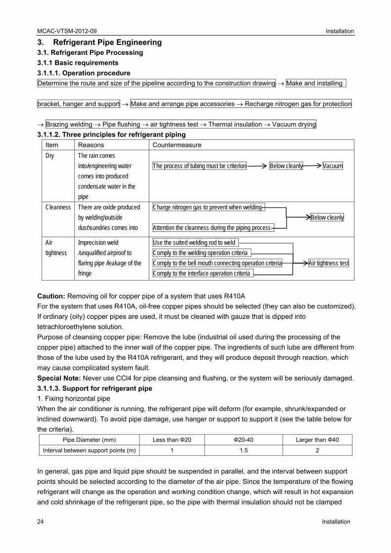
3.1.1.2. Three principles for refrigerant piping
Item Reasons Countermeasure
Dry The rain comes
into/engineering water
comes into produced
condensate water in the
pipe
The process of tubing must be criterion Below cleanly Vacuum
Cleanness There are oxide produced
by welding\outside
dust\sundries comes into
Charge nitrogen gas to prevent when welding
Below cleanly
Attention the cleanness during the piping process
Air
tightness
Imprecision weld
/unqualified airproof to
flaring pipe /leakage of the
fringe
Use the suited welding rod to weld
Comply to the welding operation criteria
Comply to the bell mouth connecting operation criteria Air tightness test
Comply to the interface operation criteria
Caution: Removing oil for copper pipe of a system that uses R410A
For the system that uses R410A, oil-free copper pipes should be selected (they can also be customized).
If ordinary (oily) copper pipes are used, it must be cleaned with gauze that is dipped into
tetrachloroethylene solution.
Purpose of cleansing copper pipe: Remove the lube (industrial oil used during the processing of the
copper pipe) attached to the inner wall of the copper pipe. The ingredients of such lube are different from
those of the lube used by the R410A refrigerant, and they will produce deposit through reaction, which
may cause complicated system fault.
Special Note: Never use CCl4 for pipe cleansing and flushing, or the system will be seriously damaged.
3.1.1.3. Support for refrigerant pipe
1. Fixing horizontal pipe
When the air conditioner is running, the refrigerant pipe will deform (for example, shrunk/expanded or
inclined downward). To avoid pipe damage, use hanger or support to support it (see the table below for
the criteria).
Pipe Diameter (mm) Less than Ф20 Ф20-40 Larger than Ф40
Interval between support points (m) 1 1.5 2
In general, gas pipe and liquid pipe should be suspended in parallel, and the interval between support
points should be selected according to the diameter of the air pipe. Since the temperature of the flowing
refrigerant will change as the operation and working condition change, which will result in hot expansion
and cold shrinkage of the refrigerant pipe, so the pipe with thermal insulation should not be clamped

MCAC-VTSM-2012-09 Installation
Installation 25
tightly, otherwise the copper pipe may get broken due to stress concentration.
2. Fixing vertical pipe
Fix the pipe along the wall according to the pipeline route. Round log should be used at the pipe clip to
replace thermal insulation material, “U”-shape pipe should be fixed outside the round log, and the round
log should be provided with anticorrosion treatment.
Pipe Diameter (mm) Less than Ф20 Ф20-40 Larger than Ф40
Interval between support points (m) 1. 5 2. 0 2. 5
3. Local fixing
To avoid stress concentration due to expansion and shrinkage of the pipe, it is usually required to
conduct local fixing beside the wall through-holes of the branch pipe and end pipe.
3.1.1.4.. Requirements for installing branch pipe subassembly
When laying the branch pipe subassembly, pay attention to the following:
1) Do not replace branch pipe with tee pipe.
2) Follow the construction drawing and installation instructions to confirm the models of branch pipe
subassembly as well as the diameters of main pipe and branch pipe.
3) Neither sharp bend (an angle of 90°) nor connection to other branch pipe subassembly is allowed at
places within 500mm away from the branch pipe subassembly.
4) Try best to install the branch pipe subassembly at a place that facilitates welding (if doing so is
impossible, it is recommended to prefabricate the subassembly).
5) Install vertical or horizontal branch joint, and ensure that the horizontal angle is within 10°. Refer to the
right side picture:
6) For avoid oil accumulate at the outdoor unit, please install the branching pipes properly.
10°
10°
A
CorrectWrong
U-shaped branching pipe
Horizontal surface
A direction view

MCAC-VTSM
26
7) To ensur
subassemb
a. Ensure t
section of t
b. Ensure t
pipes is larg
c. Ensure t
connect the
3.1.2. Stora
3.1.2.1. Pip
1. Avoid the
2. Seal the
3. Place the
4. Use woo
dust-proof a
5. Take dus
6. Keep the
3.1.2.2. Co
1. There ar
1) Sealing w
2) Sealing w
Caution: Th
● Method o
※ It is reco
● Method o
2. Special a
1) When pu
>1m
M-2012-09
re even dive
bly and the h
hat the dista
he adjacent
hat the dista
ger than or e
hat the dista
e indoor unit
age and ma
pe carriage
e pipe from
openings o
e coil uprigh
oden suppor
and water-p
st-proof and
e pipes on s
orrect to sea
re two ways
with cover o
welding (sui
he openings
of sealing wi
ommended t
of sealing we
attention:
utting the co
ersion of refr
horizontal st
ance betwee
t branch pipe
ance betwee
equal to 1m
ance betwee
t is larger th
aintain of co
and storag
bending or d
f the copper
ht to avoid co
rt to ensure t
proof.
d water-proo
pecial brack
al the open
for opening
or adhesive t
itable for lon
s of the copp
th cover or a
to seal the o
elding
opper pipe th
>
I
rigerant, pay
traight pipe.
en the bendi
e is larger th
en the horizo
.
en the branc
an or equal
opper pipe
ge
deforming d
r pipe with e
ompressing
that the cop
f measures
ket or bench
ing
sealing:
tape (suitab
ng-term stora
per pipe mus
adhesive tap
openings of t
hrough the h
>1m
Indoor unit
y attention to
ing point of
han or equa
ontal straigh
ch pipe and
to 0. 5m.
during the ca
end cover or
deformation
pper pipe is h
at both end
h at specified
ble for short-
age)
st be sealed
pe
the pipe with
hole in the w
o the distanc
copper pipe
l to 1m.
ht pipe sectio
the horizont
arriage.
adhesive ta
n due to self
higher than t
s of the pipe
d place on th
term storage
d at any time
h both cover
wall(dirt is e
>0.5m
Indoor unit
ce between
e and the hor
ons of the tw
tal straight p
ape during th
f weight.
the ground,
e.
he construct
e)
e during the
r and adhes
easy to ente
Indoor unit
the branch
rizontal stra
wo adjacent
pipe section
he storage.
so as to ma
tion site.
construction
sive tape.
er into the pip
Installation
Installation
pipe
ight pipe
branch
used to
ake the pipe
n.
pe).
n

MCAC-VTSM
Installation
2) When th
when the p
3) Before c
4) Place the
5) Before p
6) Do not p
7) When co
3.1.3 Proce
3.1.3.1. Pip
1. Tool
Use a pipe
M-2012-09
e copper pip
pipe is placed
completing th
e openings
putting the p
place the pip
onduct pipin
essing of c
pe cutting
cutter inste
pe goes out
d upright.
he pipe conn
of the pipe v
ipe outside t
pe on the gro
g on a rainin
opper pipe
ad of a saw
side the wal
nection, sea
vertically or
the wall, sea
ound directly
ng day, reme
or cutting m
ll, ensure th
al the openin
horizontally
al the openin
y, or keep it
ember to se
machine to c
at no rain w
ngs of the pi
.
ng of the pip
away from g
eal the open
cut the pipe.
ater can ent
pe with cove
pe with a cov
ground fricti
ings of the p
ter the pipe,
ers.
ver.
on.
pipe first.
Installation
27
particularly
n
7
y
MCAC-VTSM
28
2. Correct o
Rotate the
deform.
3. Risk if a
Copper chi
compresso
3.1.3.2. Re
1. Purpose
Clear out th
of the pipe,
2. Operatio
1) Use a sc
avoid copp
2) After the
3) Ensure n
4) If the pip
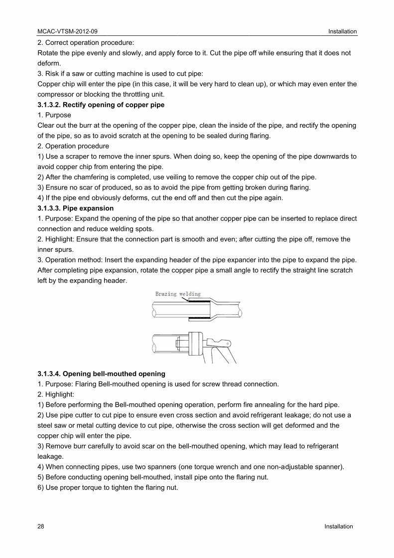
3.1.3.3. Pip
1. Purpose
connection
2. Highlight
inner spurs
3. Operatio
After comp
left by the e
3.1.3.4. Op
1. Purpose
2. Highlight
1) Before p
2) Use pipe
steel saw o
copper chip
3) Remove
leakage.
4) When co
5) Before c
6) Use prop
M-2012-09
operation pr
pipe evenly
saw or cutti
p will enter t
or or blocking
ectify openi
he burr at th
, so as to av
on procedure
craper to rem
er chip from
e chamfering
no scar of pr
pe end obvio
pe expansio
: Expand the
and reduce
t: Ensure tha
s.
on method: I
leting pipe e
expanding h
pening bell-
: Flaring Be
t:
performing th
e cutter to cu
or metal cutt
p will enter t
e burr carefu
onnecting pi
conducting o
per torque to
rocedure:
and slowly,
ng machine
the pipe (in t
g the throttlin
ng of coppe
e opening o
void scratch
e
move the inn
m entering th
g is complete
roduced, so
ously deform
on
e opening of
e welding sp
at the conne
nsert the ex
expansion, r
header.
-mouthed o
ll-mouthed o
he Bell-mou
ut pipe to en
ing device to
he pipe.
lly to avoid s
pes, use two
opening bell-
o tighten the
and apply f
e is used to c
this case, it
ng unit.
er pipe
of the coppe
at the open
ner spurs. W
e pipe.
ed, use veili
as to avoid
ms, cut the e
f the pipe so
ots.
ection part is
xpanding hea
rotate the co
pening
opening is u
thed openin
nsure even c
o cut pipe, o
scar on the
o spanners
-mouthed, in
e flaring nut.
force to it. C
cut pipe:
will be very
r pipe, clean
ing to be se
When doing s
ng to remov
the pipe fro
end off and t
o that anothe
s smooth an
ader of the p
opper pipe a
used for scre
ng operation
cross sectio
otherwise th
bell-mouthe
(one torque
nstall pipe o
Cut the pipe
hard to clea
n the inside
ealed during
so, keep the
ve the coppe
om getting b
hen cut the
er copper pi
nd even; afte
pipe expand
small angle
ew thread co
, perform fir
n and avoid
e cross sect
ed opening, w
wrench and
nto the flarin
off while ens
an up), or wh
of the pipe,
flaring.
e opening of
er chip out o
roken during
pipe again.
pe can be in
er cutting the
der into the p
e to rectify th
onnection.
e annealing
refrigerant l
tion will get
which may l
d one non-a
ng nut.
suring that i
hich may eve
and rectify t
f the pipe do
of the pipe.
g flaring.
nserted to re
e pipe off, re
pipe to expa
he straight li
for the hard
leakage; do
deformed a
lead to refrig
adjustable sp
Installation
Installation
t does not
en enter the
the opening
ownwards to
eplace direct
emove the
nd the pipe.
ne scratch
d pipe.
not use a
nd the
gerant
panner).
n
e
o
t
.
MCAC-VTSM
Installation
Pipe
Diameter
1/4" (6. 35
3/8" (9. 52
1/2" (12. 7
5/8" (15. 88
3/4" (19. 05
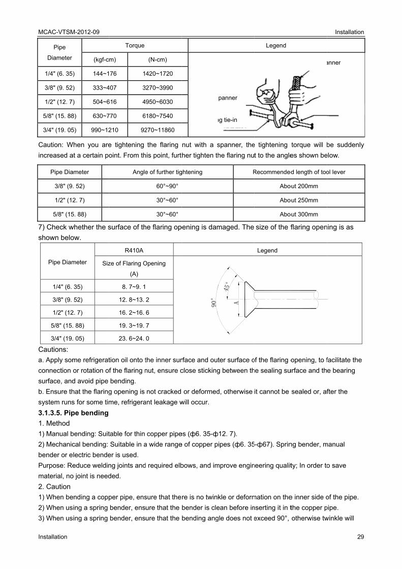
Caution: W
increased a
Pipe Dia
3/8" (9
1/2" (12
5/8" (15
7) Check w
shown belo
Pipe Diam
1/4" (6.
3/8" (9.
1/2" (12
5/8" (15.
3/4" (19.
Cautions:
a. Apply som
connection
surface, and
b. Ensure th
system runs
3.1.3.5. Pip
1. Method
1) Manual b
2) Mechanic
bender or e
Purpose: Re
material, no
2. Caution
1) When be
2) When us
3) When us
M-2012-09
(kgf-c
) 144~1
) 333~4
) 504~6
8) 630~7
5) 990~12
When you are
at a certain po
ameter
. 52)
2. 7)
5. 88)
whether the s
ow.
meter Siz
35)
52)
2. 7)
. 88)
. 05)
me refrigerat
or rotation o
d avoid pipe
hat the flaring
s for some tim
pe bending
bending: Suit
cal bending:
lectric bende
educe weldin
o joint is need
ending a copp
sing a spring
sing a spring
Torque
m)
76 1
407 3
616 4
770 6
210 92
e tightening
oint. From th
Angle
surface of th
R410A
ze of Flaring O
(A)
8. 7~9. 1
12. 8~13.
16. 2~16.
19. 3~19.
23. 6~24.
tion oil onto t
f the flaring n
bending.
g opening is
me, refrigera
table for thin
Suitable in a
er is used.
ng joints and
ded.
per pipe, ens
bender, ens
bender, ens
(N-cm)
420~1720
3270~3990
4950~6030
6180~7540
270~11860
the flaring
his point, furt
e of further tig
60°~90°
30°~60°
30°~60°
he flaring op
Opening
2
6
7
0
the inner sur
nut, ensure c
not cracked
ant leakage w
copper pipe
a wide range
d required elb
sure that the
ure that the
ure that the
nut with a s
her tighten th
ghtening
pening is dam
90°
rface and out
close sticking
or deformed
will occur.
es (ф6. 35-ф
e of copper p
bows, and im
re is no twin
bender is cle
bending ang
S
tubin
spanner, the
he flaring nu
R
maged. The 45°
A
ter surface o
g between th
d, otherwise
ф12. 7).
ipes (ф6. 35
mprove engin
kle or deform
ean before in
gle does not e
Spanner
ng tie-in
Legend
e tightening
t to the angle
Recommended
Abo
Abo
Abo
size of the f
Legend
of the flaring o
he sealing su
it cannot be
5-ф67). Sprin
neering qualit
mation on the
nserting it in t
exceed 90°,
torque will b
es shown be
d length of too
out 200mm
out 250mm
out 300mm
flaring open
opening, to f
urface and th
sealed or, af
ng bender, m
ty; In order to
e inner side o
the copper p
otherwise tw
torque spa
Flaring
Installation
29
be suddenly
elow.
ol lever
ning is as
facilitate the
e bearing
fter the
manual
o save
of the pipe.
pipe.
winkle will
anner
opening nut
n
9
y

MCAC-VTSM
30
appear on t
4) Ensure th
pipe is large
3.1.4 Brazi
3.1.4.1. Se
1. All pipe u
thickness, e
2. Specifica
3. Try best
Note: Selec
Outer
Diameter
Ф6. 35
Ф9. 52
Ф12. 7
Ф15. 9
3.1.4.2. Nit
1. Purpose
2. Risks of
If no sufficie
inner wall o
malfunction
To avoid th
welding, an
and the cop
below.
M-2012-09
he inner side
hat the pipe d
er than 2/3 o
the pipe
ing welding
lecting refr
use shall co
etc.)
ation: Seam
to use straig
ct the pipes
Material
O
O
O
O
trogen fillin
: Avoid oxid
non-protect
ent nitrogen
of the coppe
ns such as b
hese problem
nd ensure th
pper pipe co
e of the pipe,
does not sink
f the original
e sink easily
g operation
rigerant pip
mply with na
less phosph
ght pipe or c
according to
Minimum
Thickness
0. 8
0. 8
0. 8
1. 0
ng for prote
e scale from
tive welding:
n is charged
r pipe. Thes
burn-out the
ms, charge n
hat the nitrog
ools down co
, and the pip
k during the b
area, otherw
on the side
e
ational or loc
horus to oxyg
coil and avo
o the pipe d
Outer
Diameter
Ф19. 0
Ф22. 0
Ф25. 0
Ф28. 6
cting coppe
m appearing
:
into the refr
se oxides wil
compresso
nitrogen con
gen passes t
ompletely. T
pe may easily
bending proc
wise it canno
twink
cal standard
genate copp
oid too much
iameters sh
Material
O
1/2H
1/2H
1/2H
er pipe dur
on the inne
rigerant pipe
ll block the r
r, poor cooli
ntinuously in
through the
The schemat
y get broken.
cess; ensure
ot be used.
kle will easil
ds (for exam
per pipe
h brazing we
own below (
Minimum
Thickness
1. 0
1. 2
1. 2
1. 3
ing brazing
er wall of the
e being weld
refrigerant sy
ing efficienc
to the refrig
operating p
tic diagram f
.
that the cros
ly appear on t
mple, pipe dia
lding.
(O—coil, 1/2
Outer
Diameter
Ф38. 0
Ф45. 0
Ф54. 0
Ф67. 0
g welding
e copper pipe
ed, oxides w
ystem, which
y.
erant pipe d
point until the
for nitrogen
ss section of
this side
ameter, mat
2H—straigh
Material
1/2H
1/2H
1/2H
1/2H
e in the high
will be gener
h will lead to
during the br
e welding is
charging is
Installation
Installation
f the bending
terial,
t pipe)
Minimum
Thickness
1. 5
1. 5
1. 8
1. 8
h temp.
rated on the
o all kinds of
razing
completed
shown
n
g
e
f
MCAC-VTSM-2012-09 Installation
Installation 31
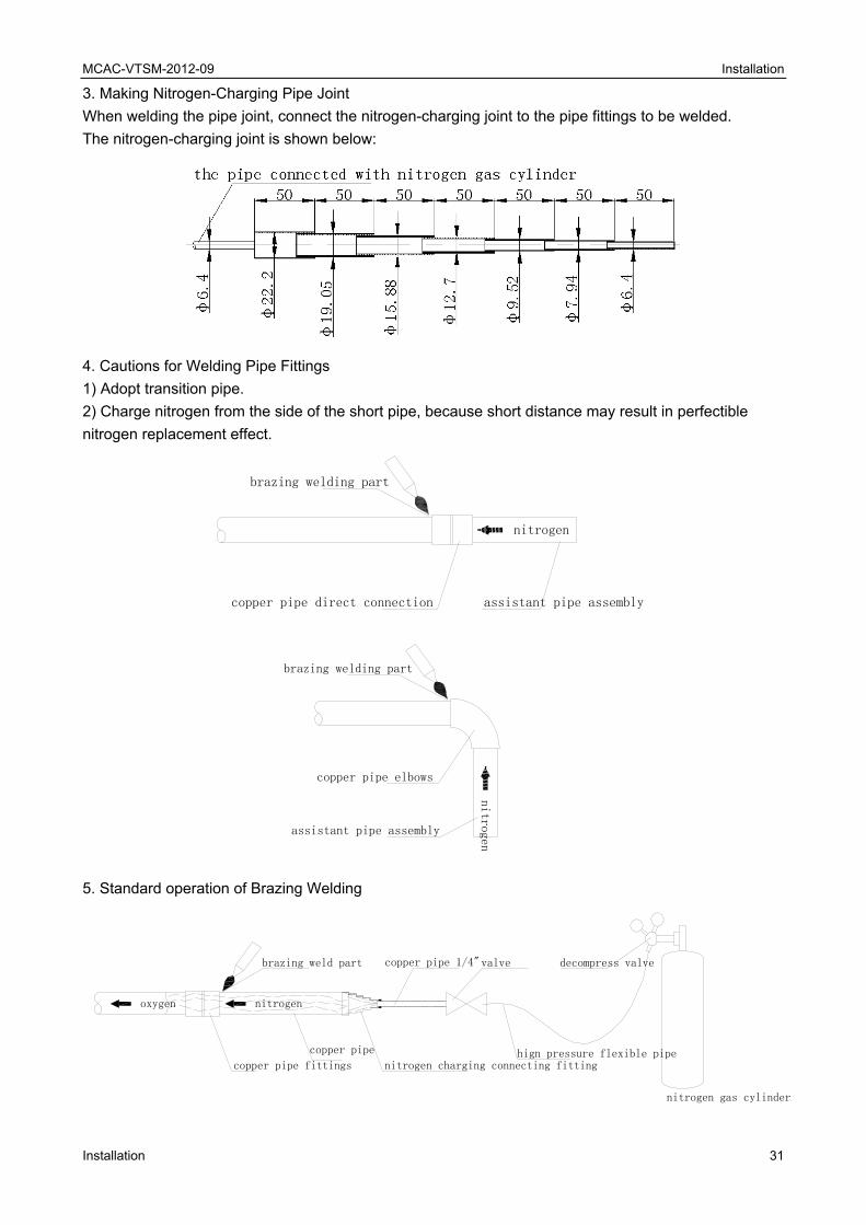
3. Making Nitrogen-Charging Pipe Joint
When welding the pipe joint, connect the nitrogen-charging joint to the pipe fittings to be welded.
The nitrogen-charging joint is shown below:
4. Cautions for Welding Pipe Fittings
1) Adopt transition pipe.
2) Charge nitrogen from the side of the short pipe, because short distance may result in perfectible
nitrogen replacement effect.
nitrogen
brazing welding part
assistant pipe assemblycopper pipe direct connection
brazing welding part
copper pipe elbows
assistant pipe assembly
nitr
ogen
5. Standard operation of Brazing Welding
copper pipe 1/4"
copper pipe fittings
copper pipe
nitrogen gas cylinder
hign pressure flexible pipe
decompress valvevalve
nitrogen charging connecting fitting
brazing weld part
oxygen nitrogen

MCAC-VTSM
32
6. Highlight
1) Control t
2) Ensure t
3) Use pres
4) Select a
5) Ensure t
6) If the pip
that the nitr
7) After com
8) Try best
7. Cautions
1) Take fire
beside the
2) Avoid ge
3) Pay atte
Note: The f
pipe joint.
side
3.1.5 Pipe
3.1.5.1. Flu
1. Function
trash and m
protection o
2. Purpose
1) Eliminate
2) Help to c
3. Risk in c
If the remai
malfunction
3.1.5.2. Pro
M-2012-09
t
the nitrogen
the gas is ni
ssure reduci
proper posi
that the nitro
peline betwe
rogen is cha
mpleting the
to conduct w
s
e-prevention
operating po
etting burnt.
ntion to the
follow table
Typ
B
bre
cleaning ou
ushing copp
n: use pressu
moisture. So
of copper pi
e oxide pow
clear out dirt
case of no flu
ining solid im
ns shall hap
ocedure of
pressure to
trogen; oxyg
ing valve, an
ition for char
ogen passes
een the posit
arged for suf
e welding, ch
welding dow
n measures w
osition).
fit gap of the
shows the r
pe
AD
azing weld
ut
per pipe
ure gas to fl
olid impurity
peline durin
wder or part o
t and humid
ushing:
mpurity and
pen, such a
flushing
o be about 0
gen will easi
nd control th
rging nitroge
s through the
tion for char
fficient time
harge the nit
wnwards or h
when condu
e position w
elation betw
O
ding
ush pipeline
is hard to be
g constructio
oxide layer i
ity in pipe.
moisture in
s ice blocka
0.2-0.3kgf/cm
ily leads exp
he pressure
en.
e welding sp
rging nitroge
so as to dis
trogen conti
horizontally
ucting weldin
where the pip
ween the min
Outer Diamete
Pipe (D) (mm
5<D<8
8<D<12
11<D<16
16<D<25
25<D<35
35<D<45
e (raw mater
e washed ou
on.
in copper pip
pipeline cou
age, dirt bloc
m² during the
plosion, so it
of the charg
pots.
en and the w
charge all th
nuously unt
and avoid fa
ng (ensure t
pe is inserte
nimum embe
er of
m)+
Min
De
rial or welde
ut, so specia
pe.
uld not be e
ckage and co
e welding.
t is forbidden
ed nitrogen
welding spot
he air from th
il the pipe co
ace-down w
hat a fire ex
d.
edded depth
nimum Inlaid
pth (B) (mm)
6
7
8
10
12
14
d assembly
al attention s
liminated eff
ompressor b
n.
to be about
is rather lon
he welding s
ools down c
welding.
xtinguisher is
h and gap at
Gap A—
0. 05
0. 05
0. 05
y) for elimina
shall be draw
ffectively, se
being jamme
Installation
Installation
t 0.2kg/ cm².
ng, ensure
spot.
completely.
s available
t the copper
—D (mm)
5—0. 21
5—0. 27
5—0. 35
ating dust,
wn to the
erious
ed.
n
.
r
MCAC-VTSM-2012-09 Installation
Installation 33
1. Mounting pressure adjusting valve on nitrogen gas cylinder. The applied gas must be nitrogen. If
adopting polytetrafluoro ethylene or carbon dioxide, there is a risk of condensation. If using oxygen,
there is a risk of explosion.
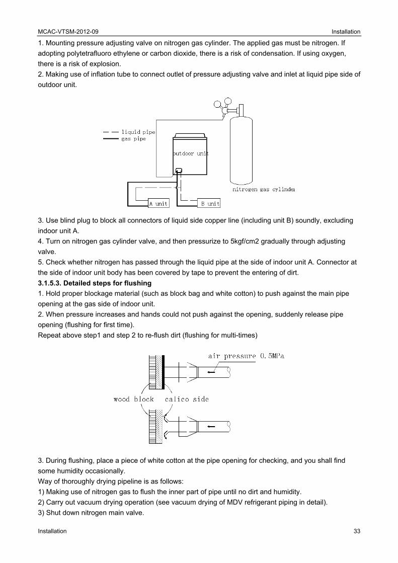
2. Making use of inflation tube to connect outlet of pressure adjusting valve and inlet at liquid pipe side of
outdoor unit.
3. Use blind plug to block all connectors of liquid side copper line (including unit B) soundly, excluding
indoor unit A.
4. Turn on nitrogen gas cylinder valve, and then pressurize to 5kgf/cm2 gradually through adjusting
valve.
5. Check whether nitrogen has passed through the liquid pipe at the side of indoor unit A. Connector at
the side of indoor unit body has been covered by tape to prevent the entering of dirt.
3.1.5.3. Detailed steps for flushing
1. Hold proper blockage material (such as block bag and white cotton) to push against the main pipe
opening at the gas side of indoor unit.
2. When pressure increases and hands could not push against the opening, suddenly release pipe
opening (flushing for first time).
Repeat above step1 and step 2 to re-flush dirt (flushing for multi-times)
3. During flushing, place a piece of white cotton at the pipe opening for checking, and you shall find
some humidity occasionally.
Way of thoroughly drying pipeline is as follows:
1) Making use of nitrogen gas to flush the inner part of pipe until no dirt and humidity.
2) Carry out vacuum drying operation (see vacuum drying of MDV refrigerant piping in detail).
3) Shut down nitrogen main valve.
MCAC-VTSM-2012-09 Installation
34 Installation
4) Repeat above operations to the connected copper pipe of all indoor units.
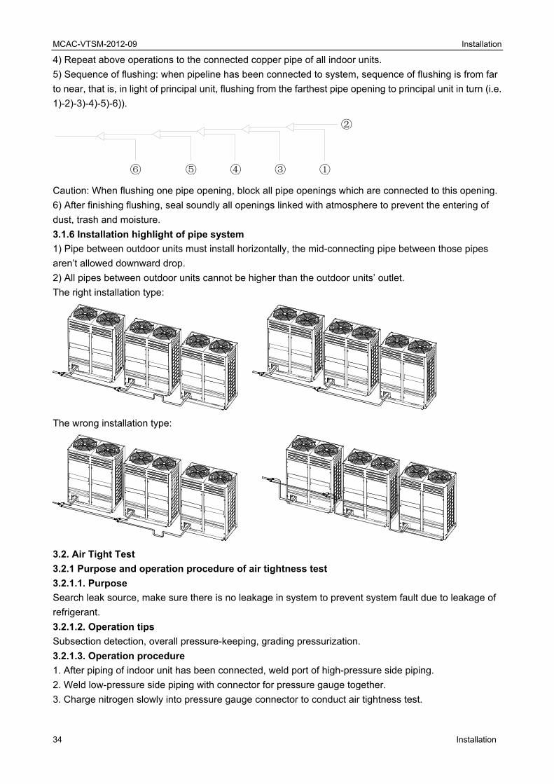
5) Sequence of flushing: when pipeline has been connected to system, sequence of flushing is from far
to near, that is, in light of principal unit, flushing from the farthest pipe opening to principal unit in turn (i.e.
1)-2)-3)-4)-5)-6)).
②
⑥ ⑤ ④ ③ ①
Caution: When flushing one pipe opening, block all pipe openings which are connected to this opening.
6) After finishing flushing, seal soundly all openings linked with atmosphere to prevent the entering of
dust, trash and moisture.
3.1.6 Installation highlight of pipe system
1) Pipe between outdoor units must install horizontally, the mid-connecting pipe between those pipes
aren’t allowed downward drop.
2) All pipes between outdoor units cannot be higher than the outdoor units’ outlet.
The right installation type:
The wrong installation type:
3.2. Air Tight Test
3.2.1 Purpose and operation procedure of air tightness test
3.2.1.1. Purpose
Search leak source, make sure there is no leakage in system to prevent system fault due to leakage of
refrigerant.
3.2.1.2. Operation tips
Subsection detection, overall pressure-keeping, grading pressurization.
3.2.1.3. Operation procedure
1. After piping of indoor unit has been connected, weld port of high-pressure side piping.
2. Weld low-pressure side piping with connector for pressure gauge together.
3. Charge nitrogen slowly into pressure gauge connector to conduct air tightness test.

MCAC-VTSM-2012-09 Installation
Installation 35
3.2.2 Operation of air tightness test
3.2.2.1. Operation procedure
1. When conducting air tightness test, make sure that gas pipe and liquid pipe are kept in full-shut status;
otherwise, nitrogen might enter the circulation system of outdoor unit. Both gas valve and liquid valve
need to be strengthened before pressurization d.
2. Each refrigerant system shall be slowly pressurized from the two sides of gas pipe and liquid pipe.
3. Make use of dry nitrogen as medium to conduct air tightness test. Phase-in control diagram of
pressurization is as follows:
No. Phase (phase-in pressurization) Criteria
1 Phase 1: appear large leakage after over three minutes of pressurization with 3.0kgf/cm2. No pressure drop
after modification2 Phase 2: appear major leakage after over three minutes of pressurization with 15. 0kgf/cm2.
3 Phase 3: appear small leakage after over 24 hours of pressurization with R410A: 40.0kgf/cm2.
3.2.2.2. Pressure observation
1. Pressurize to regulated value and maintain 24 hours. When modifying pressure according to variation
of temperature, it is qualified if pressure drop does not happen. If pressure falls, find out the leak source
and modify it.
2. Modification method
When ambient temperature difference is ±1℃, the pressure difference shall be ±0.1 kgf/cm2.
Modification formula: Real value = pressure of pressurization + (temperature of pressurization –
temperature during observation) x 0.1 kgf/cm2
You can find out whether the pressure drops or not by comparing the modification value with
pressurization value.
3. General ways for searching leak source
Conduct detection through three phases; find out leak source when pressure drop happens.
1) Audition detection-----hear large leakage sound
2) Hand-touching detection-----place hand at the joint of pipeline to feel whether there is leakage
3) Soap water detection-----bubbles shall burst out from leak source.
4) Detection by use of halogen leak detector
Using halogen leak detector when finding out pressure drop but not finding the leak source.
a. Keep nitrogen at 3.0kgf/cm2.
b. Supplement refrigerant to 5.0kgf/cm2.
c. Use halogen leak detector, methane leak detector and electric leak detector for detection.
d. If the leak source still could not be found, continuously pressurize to 40.0kgf/cm2 (R410A) and then
detect again.
1
2
3
4
1
2
3
4
Oil balancer
Liquid side stop valve
Gas side stop valve
Gauge point(Use for detecting pressure and refrigerant)
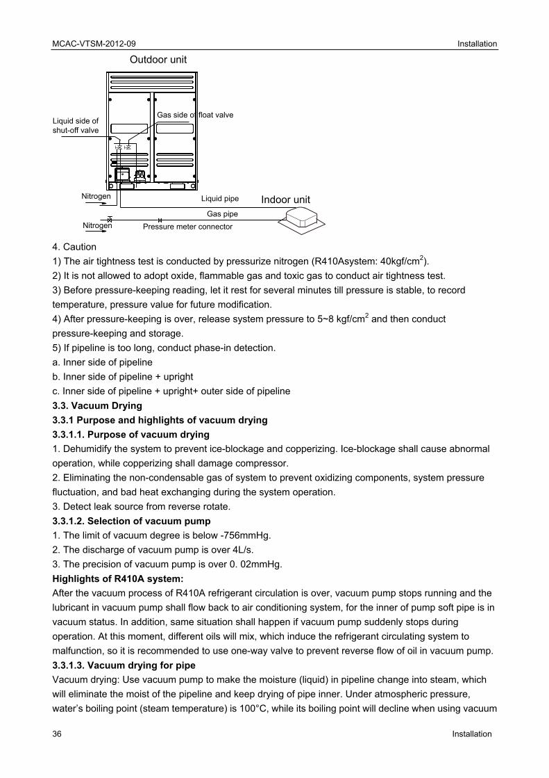
MCAC-VTSM-2012-09 Installation
36 Installation
4. Caution
1) The air tightness test is conducted by pressurize nitrogen (R410Asystem: 40kgf/cm2).
2) It is not allowed to adopt oxide, flammable gas and toxic gas to conduct air tightness test.
3) Before pressure-keeping reading, let it rest for several minutes till pressure is stable, to record
temperature, pressure value for future modification.
4) After pressure-keeping is over, release system pressure to 5~8 kgf/cm2 and then conduct
pressure-keeping and storage.
5) If pipeline is too long, conduct phase-in detection.
a. Inner side of pipeline
b. Inner side of pipeline + upright
c. Inner side of pipeline + upright+ outer side of pipeline
3.3. Vacuum Drying
3.3.1 Purpose and highlights of vacuum drying
3.3.1.1. Purpose of vacuum drying
1. Dehumidify the system to prevent ice-blockage and copperizing. Ice-blockage shall cause abnormal
operation, while copperizing shall damage compressor.
2. Eliminating the non-condensable gas of system to prevent oxidizing components, system pressure
fluctuation, and bad heat exchanging during the system operation.
3. Detect leak source from reverse rotate.
3.3.1.2. Selection of vacuum pump
1. The limit of vacuum degree is below -756mmHg.
2. The discharge of vacuum pump is over 4L/s.
3. The precision of vacuum pump is over 0. 02mmHg.
Highlights of R410A system:
After the vacuum process of R410A refrigerant circulation is over, vacuum pump stops running and the
lubricant in vacuum pump shall flow back to air conditioning system, for the inner of pump soft pipe is in
vacuum status. In addition, same situation shall happen if vacuum pump suddenly stops during
operation. At this moment, different oils will mix, which induce the refrigerant circulating system to
malfunction, so it is recommended to use one-way valve to prevent reverse flow of oil in vacuum pump.
3.3.1.3. Vacuum drying for pipe
Vacuum drying: Use vacuum pump to make the moisture (liquid) in pipeline change into steam, which
will eliminate the moist of the pipeline and keep drying of pipe inner. Under atmospheric pressure,
water’s boiling point (steam temperature) is 100°C, while its boiling point will decline when using vacuum
Outdoor unit
Indoor unitNitrogen
Nitrogen
Liquid pipe
Gas pipe
Liquid side ofshut-off valve
Gas side of float valve
Pressure meter connector

MCAC-VTSM-2012-09 Installation
Installation 37
pump reduce the pipeline pressure to vacuum. When the boiling point declines under outdoor
temperature, moisture in pipe shall be evaporated.
Boiling Point of
Water (℃)
Air Pressure
(mmHg)
Vacuum Degree
(mmHg)
Boiling Point of
Water (℃)
Air Pressure
(mmHg)
Vacuum Degree
(mmHg)
40 55 -705 17. 8 15 -745
30 36 -724 15 13 -747
26. 7 25 -735 11. 7 10 -750
24. 4 23 -737 7. 2 8 -752
22. 2 20 -740 0 5 -755
20. 6 18 -742
3.3.2 Operation procedure for vacuum drying
3.3.2.1. Methods of vacuum drying
By different construction environment, there are two kinds of vacuum drying ways: ordinary vacuum
drying and special vacuum drying.
3.3.2.1.1. Ordinary vacuum drying
1) Firstly, connect the pressure gauge to the infusing mouth of gas pipe and liquid pipe, keep vacuum
pump running for above 2 hours, and it is quality that vacuum degree of vacuum pump is below
-755mmHg.
2) If the vacuum degree of vacuum pump could not be below -755mmHg after 2 hours of drying, system
will continue drying for one hour.
3) If the vacuum degree of vacuum pump could not be below -755mmHg after 3 hours of drying, please
check the system leakage source.
4) Vacuum placement test: when the vacuum degree reaches -755mmH, keep rest for 1 hour. If the
indicator of vacuum gauge does not go up, it is qualified. If going up, it indicates that there is moisture
and leak source.
5) Vacuum drying shall be conduct from liquid pipe and gas pipe simultaneously. There are a lot of
functional parts like valves, which could shut down the gas flow midway.
3.3.2.1.2. Special vacuum drying
This kind of vacuum drying method shall be adopted when:
1) Finding moisture during flushing refrigerant pipe.
2) Conducting construction on rainy day, because rain water might penetrated into pipeline.
3) Construction period is long, and rain water might penetrated into pipeline.
4) Rain water might penetrate into pipeline during construction.
Procedures of special vacuum drying are as follows:
a. The first vacuum drying 2 hours.
b. The second vacuum damage, filling nitrogen to 0.5Kgf/cm2.
Because nitrogen is dry gas, vacuum damage could achieve the effect of vacuum drying, but this
method could not achieve drying thoroughly when there is too much moisture. Therefore, special
attention shall be drawn to prevent the entering of water and the formation of condensate water.
c. The second vacuum drying 1 hour.
It is qualified when vacuum degree is under -755mmHg; if the vacuum degree is still above -755mmHg
within 2 hours drying, please repeat the procedures of “vacuum damage---vacuum drying”.
d. Vacuum placement test: when the vacuum degree reaches -755mmH, keep rest for 1 hour. If the
indicator of vacuum gauge does not go up, it is qualified. If going up, it indicates that there is moisture
and leak source.

MCAC-VTSM-2012-09 Installation
38 Installation
3.4. Recharge of Refrigerant
3.4.1 Operation procedure for recharging refrigerant
3.4.1.1. Operation procedure
Calculate the required refrigerant volume by the length of liquid pipe → recharging refrigerant.
※The refrigerant volume from factory does not include the recharged amount of the pipeline extending.
3.4.1.2. Detailed steps for recharging refrigerant
1. Make sure vacuum drying is qualified before recharging refrigerant.
2. Calculate the required refrigerant volume by the dia. and the length of liquid pipe.
3. Use electronic scale or fluid infusion apparatus to weight the recharged refrigerant volume.
4. Use soft pipe to connect refrigerant cylinder, pressure gauge, and examine valve of outdoor unit. And
recharge with liquid mode. Before recharging, eliminate the air in the soft pipe and pressure gauge’s pipe.
5. After finishing the recharging, by the gas leak detector or soap water, to detect whether there is
refrigerant leakage in expansion part of indoor and outdoor units.
6. Write the recharged refrigerant volume in the indicating plate of outdoor unit.
Caution
1) The recharged refrigerant volume must be calculated according to the formula in the technical
reference of outdoor unit. It isn’t allowed to calculate by running current, pressure and temperature.
Because current and pressure is changeable due to the difference of temperature and length of pipeline.
2) In the cold ambient, use warm water and hot wind to warm up refrigerant storage cylinder, and don’t
allow heating up directly by flame.
3.4.1.3. Recharging of R410A refrigerant
If R410A refrigerant is adopted, the tool shall be different. Confirm the following items before Recharged:
1) The different vacuum pump with one-way valve.
2) The different pressure gauge: the nut of connector and pressure scale are different.
3) The different recharging soft pipe and connector.
4) The charging method is different. Recharge into the outdoor unit with liquid phase.
5) The different leak detector.
3.4.2 Calculating the recharged refrigerant volume
Calculate the recharged refrigerant volume by the length and dia. of liquid pipe of indoor units
R410A
Diameter of Liquid Pipe Equivalent Refrigerant for
Pipe Length of 1m (kg/m) Diameter of Liquid Pipe
Equivalent Refrigerant for
Pipe Length of 1m (kg/m)
Ф6. 4 0.023 Ф19. 1 0.270
Ф9. 5 0.060 Ф22. 2 0.380
Ф12. 7 0.120 Ф25. 4 0.520
Ф15. 9 0.170 Ф28. 6 0.680
Calculating formula (R410A):
The recharged volume: R (Kg) = (L1×0. 023 kg/m) + (L2×0. 060 kg/m) + (L3×0. 120 kg/m) + (L4×0.180
kg/m) + (L5×0. 270 kg/m) + (L6×0. 380 kg/m) + (L7×0. 520kg/m) + (L8×0. 680kg/m)
L1: Actual total length of Φ6.4 liquid pipe (m); L2: Actual total length of Φ9.5 liquid pipe (m);
L3: Actual total length of Φ12.7 liquid pipe (m); L4: Actual total length of Φ15.9 liquid pipe (m);
L5: Actual total length of Φ19.1 liquid pipe (m); L6: Actual total length of Φ22.2 liquid pipe (m);
L7: Actual total length of Φ25.4 liquid pipe (m); L8: Actual total length of Φ28.6 liquid pipe (m)

MCAC-VTSM
Installation
4. Drain4.1 Installa
4.1.1. Insta
1) Slope; 2
4.1.2. Insta
1. Before in
with other p
2. Make su
and drainag
a. Correct c
b. Incorrect
Advantage
1. Do not c
2. The slop
Disadvanta
1. Interfere
2. The side
leading to t
3. Suspend
In general,
equipped w
bending, th
4. The high
could be di
5. After finis
the smooth
6. Use spec
M-2012-09
nage Pipe ation Highli
allation prin
) reasonable
allation high
nstalling con
pipelines an
re that the tw
ge difficulty.
connection:
t connection
es of correc
ause flow ba
pe of two pip
ages of inc
drainage.
e of branch p
the water ba
der gap:
the horizon
with not less
hus leading t
hest point of
scharged sm
shing conne
hness of dra
cific glue to
Engineerghts of Dra
nciple of dra
e pipe diame
hlights of d
ndensate wa
d ensure slo
wo horizonta
n:
ct connectio
ackwards of
pes can be re
correct conn
pipe with larg
ackwards of
tal gap is 0.
than two su
to air resista
drainage pi
moothly. The
ection, condu
inage and le
adhesive th
ring ainage Pipe
ainage pipe
eter; 3) near
drainage pip
ater pipeline,
ope is smoo
al fluid pipes
on:
f one pipe.
egulated se
nection:
ge quantity o
branch pipe
8m-1m and
uspenders. O
ance.
pe shall be
e outlet air h
uct water pa
eakage of pi
he seam of th
e
e:
rby discharg
pe:
, determine
oth and straig
s shall avoid
parately.
of fluid volum
e with small
the vertical
Overlarge su
designed w
hole shall fac
assing test a
peline syste
hermal insu
ge
its route and
ght.
d encounteri
me will flow
quantity.
gap is 1.5m
uspender ga
ith air hole t
ce down to p
and overflow
em.
lation mater
d elevation t
ng, and prev
to the side w
m-2.0m. Each
ap for horizo
o ensure tha
prevent dirt
wing water te
rials, and the
to avoid inte
venting flow
with small qu
h vertical pip
ontal pipe sh
at condensa
entering pip
est to pipelin
en bind with
Installation
39
ersection
w backwards
uantity, thus
pe shall be
hall create
ate water
pe.
nes to check
rubber or
n
9
s
s
k

MCAC-VTSM
40
plastics adh
and preven
7. The drain
and other d
8. The slop
9. In case 1
10. Conflux
transverse
11. The end
4.1.3. Caut
1. The drain
2. The outle
3. Check w
into the wa
4. All joints
5. The drain
6. Dimensio
indoor unit.
7. Work ou
insulation p
8. Indoor un
9. Discharg
10. As for lo
pipe.
※ The sup
air resistan
water level
4.2 Water S
4.2.1. To in
pipe must b
M-2012-09
hesive tape.
nt condensat
nage pipe o
drainage pip
pe of drainag
1/100 slope
x towards ho
route, reflux
d of drainag
tion
nage pipe d
et air vent ca
whether cond
ter-containin
shall be firm
nage pipe is
on of draina
.
t thermal ins
processing s
nits with diff
ge of conden
ong drainag
pport gap of
ce, while air
. As shown
Storing Elb
ndoor unit w
be equipped
. The width o
tion.
of air conditio
pe in building
ge pipe shal
can not nee
orizontal pip
x is easy to b
ge pipe shall
iameter sha
annot be ins
densate wat
ng plate of in
m (particular
s not allowed
age pipe sha
sulation of d
shall be cont
ferent drainin
nsate water
ge pipe, hang
horizontal p
r resistance
in following
bow of Drain
ith large neg
d with water
of the adhes
oner shall be
g.
l be kept ab
ed, consider
e shall come
be created.
not contact
all meet the d
stalled nearb
er pump can
ndoor unit a
rly PVC pipe
d to turn to a
all be not les
drainage pipe
tinued to the
ng pattern s
cannot influ
ging bolt sha
ipe is 0.8-1.
could seriou
figure:
nage Pipe
gative press
storing elbo
sive tape sh
e installed s
bove 1/100.
r to use large
e from upsid
t with ground
draining req
by the lifting
n be started
and powering
e).
adverse slop
ss than the c
e, otherwise
e connecting
shall not sha
uence norma
all be used t
.0mm. If the
usly influenc
sure at the o
ow.
all not be le
eparately w
er-sized pipe
de as much
d directly.
quirement of
pump of the
up and shu
g on.
pe, horizonta
connecting m
e it is easy to
g part of indo
are the same
al life and wo
to ensure 1/
gap is too l
ce smoothne
utlet of wate
ss than 50m
ith other was
e and use its
as possible
indoor unit.
e indoor uni
ut down norm
al, and bend
mouth size o
o produce co
oor unit.
e concentrat
orking of oth
/100 slope w
arge, it shal
ess of water
er-containing
mm to ensur
ste pipe, rai
s dia. to cre
. If it comes
.
t.
mally by infu
ding.
of drain pipin
ondensation
ted drainage
her people.
without bend
l produce be
flow to caus
g plate, the d
Installation
Installation
e fastness
nwater pipe
ate slope.
from
using water
ng to
n. Thermal
e pipe.
ding PVC
ending and
se abnormal
drainage
n
e
l

MCAC-VTSM
Installation
Function o
When indoo
water out o
Installation
1. Install wa
2. Install on
3. When ins
4.3 Concen
4.3.1. Pipe
Select drain
E.g. If one
volume of t
4.3.2. Rela
Attention: t
4.3.3. Rela
Attention: t
4.3.4. Oper
Install indoo
insulation o
M-2012-09
of water sto
or unit is in
of the air out
n of water s
ater storing
ne water sto
stallation, co
ntrated Dra
eline diamet
nage pipe d
1HP unit wit
three 2HP u
tion betwee
hrough conv
tion betwee
hrough conv
ration proc
or unit → co
of drainage p
oring elbow
motion, prev
let.
storing elbo
elbow as sh
oring elbow f
onsider it sh
ainage Pipe
ter of conce
iameter acc
th 2L/h disc
nits and two
n horizontal
verge point n
n vertical pip
verge point n
ess of conc
onnect drain
pipe
:
vent generat
ow:
hown in follo
for each unit
hall be conve
entrated dra
cording to ind
harging con
o 1.5HP unit
pipeline dia
need use PV
peline diame
need use PV
centrated d
age pipe →
ting negativ
owing figure:
t.
enient in futu
ainage pipe
door unit’s c
densate wa
ts is: 2HP x
ameter and
VC40 or larg
eter and dis
VC40 or larg
drainage
→ water pass
e pressure t
: H shall be
ure clean.
e
combined flo
ter, the calc
2L/h x 3 + 1
permitted di
ger pipe.
placement o
ger pipe.
ing test and
to cause dra
above 50mm
ow volume.
culation of th
.5HP x 2L/h
splacement
of condensa
overflowing
ainage diffic
m.
he combined
h x 2 =18L
t of condens
ate water
g water test
Installation
41
ulty or blow
d flow
sate water
→ thermal
n

MCAC-VTSM
42
Caution:
1) Increase
horizontal m
2) Units wit
separately.
3) Add two
into pipe to
4.4 Lifting
4.4.1. Insta
1. When co
is not perm
2. To ensur
not set ven
otherwise it
follows:
Note: Air ou
could not b
4.5 Overflo
4.5.1. Over
After finishi
check whet
4.5.2. Wate
1. Natural d
Infuse wate
transparent
2. Pump dr
1) Remove
plate with a
pump.
M-2012-09
e drainage p
main drainag
th drainage
elbows at a
o create bloc
of Drainag
allation of li
onnecting dr
mitted for ens
re 1/100 slop
t pipe on the
t will cause
utlet could n
be discharge
owing Wate
rflowing wa
ing the cons
ther there is
er passing t
drainage mo
er-containing
t hard pipe a
rainage mod
e plug of wat
about 2000m
oint as muc
ge pipe not
pump and n
air outlet, an
ckage.
e Pipe (for
ift pipe
rainage pipe
suring conve
pe, total lift h
e lifting pipe
error operat
not be install
ed.
er Test and W
ater test
struction of d
s leakage at
test
ode
g plate with
at drainage
de
ter level swit
ml water thro
h as possibl
be too long.
natural drain
d make sure
the Unit wit
e with indoor
enience in re
height of dra
e section. Aft
tion of switch
led on the lif
Water Pass
drainage pipe
joint section
above 600m
outlet to con
tch, remove
ough water-f
le and reduc
.
age shall co
e its mouth f
th Lift Pum
r unit, use pi
epairing.
ainage pipe
ter lifting ver
h at water p
fting part; ot
sing Test
e system, fil
n.
ml water thro
nfirm whethe
water-findin
finding port t
ce quantity o
onverge to d
faces down
mp)
ipe clamp sh
(H) shall dep
rtically, imm
ump. The co
therwise wat
ll the pipe w
ough check
er it can disc
ng cover and
to prevent to
of connected
different drai
to prevent d
hipped with
pend on indo
ediately pla
onnecting m
ter shall be d
ith water and
port slowly,
charge wate
d slowly infu
ouching the
d indoor unit
nage system
dirt and so o
unit to fix. G
oor unit’s pu
ce down inc
method is sh
discharged
d keep it for
and observ
er.
use water-co
motor of dra
Installation
Installation
ts, to ensure
m
on dropping
Glue splicing
ump, and do
clined,
own as
to ceiling or
r 24 hours to
e
ontaining
ainage
n
e
g
o
r
o

MCAC-VTSM
Installation
2) Power o
and then tu
at drainage
shall be dis
3) Stop the
original pla
a. After sto
later. If drai
alarm indic
plate.
b. Continuo
discharge w
cause shut
down powe
Note: Drain
water-conta
filled in to p
M-2012-09
n and let the
urn on water
e outlet to co
scharged aft
e operation o
ce.
pping the op
inage pipe h
ator at remo
ously add wa
water at onc
down of uni
er supply an
n plug at the
aining plate
prevent leak
e air conditio
r level switch
onfirm wheth
ter delaying
of air conditio
peration of a
have not bee
ote-controlle
ater until rea
ce. If water le
t. When this
d eliminating
e main water
when maint
age.
oner operate
h, check ope
her it can dis
about 1 min
oner, turn do
air conditione
en distributed
ed receiving
aching alarm
evel does no
s situation ha
g accumulat
r-containing
taining air co
e for cooling
eration soun
scharge wate
nute)
own power s
er, check w
d properly, o
board and e
m water leve
ot decline un
appens, nor
ted water.
plate is use
onditioner fa
g. Check ope
nd of pump a
er. (In light o
supply and p
hether there
over back-flo
even water s
el, check whe
nder warning
rmal startup
ed for elimin
ault. During n
eration statu
and observe
of the length
put water-fin
e is somethin
ow water sha
shall run ove
ether the dra
g water leve
shall be car
ating accum
normal oper
us of drainag
e transparen
of drainage
nding cover
ng abnorma
all cause the
er the water
ainage pum
l 3 minutes
rried out by
mulated wate
ration, the p
Installation
43
ge pump,
nt hard pipe
e pipe, water
to the
al 3 minutes
e flashing of
-containing
p could
later, it shall
turning
er in
lug shall be
n
3
r
f
l

MCAC-VTSM
44
5. Duct 5.1. Fabric
1. The mate
relevant reg
steel sheet
Thickness o
2. The mate
with design
3. The body
non-combu
requiremen
4. The shea
material sh
5. The perm
when more
Discrepanc
between tw
5.2. Conne
1. Connect
1) The seam
2) Specifica
Specificatio
Specificatio
M-2012-09
Engineercation of Du
erial, specifi
gulations of
should not
of steel shee
erial, specifi
n and regula
y, frame, fix
ustible mater
nt.
athing of co
ould be no b
mitting devia
e than 300m
cy between t
wo diameters
ection of Du
ion of metal
m of duct bo
ation of meta
on to flange
on to flange
ring uct
cation, perfo
present Nat
be less than
et duct (mm
ication, perfo
ations of pres
ing material
rials. Its fire
mposite duc
burning or b
ation to outer
m, it is 3mm
two diagona
s of any cros
uct
duct
oard splice s
al duct flang
and bolt of c
and bolt of
ormance an
tional Produ
n the regulat
m)
ormance an
sent Nationa
and sealed
resistance r
ct should be
burning retar
r diameter o
m. The perm
al lines of rec
ss-cut circul
should be st
ge shall not b
circular meta
rectangle m
d thickness
ucts Standar
tion in table
nd thickness
al Products
d cushion of
rating should
made of no
rdant with ra
or long edge
itting deviati
ctangle duct
ar flange sh
tagger and c
be less than
al duct (mm
etal duct (m
of metal duc
rd. The thick
below:
of non-meta
Standard.
fire-proof ai
d be in acco
on-combustib
ating B1, and
of duct: whe
ion of pipe e
t shall not be
hall not be m
cross-seam
n the data as
m)
mm)
ct should be
kness of stee
al duct shou
r duct shoul
ordance with
ble materials
d no harm to
en no more
end flatness
e more than
more than 2m
is not allowe
s shown in ta
e in accorda
el sheet or g
uld be in com
ld be made
h the design
s. Inner insu
o people’s b
than 300mm
is 2mm.
n 3mm. Disc
mm.
ed.
able below.
Installation
Installation
nce with the
galvanized
mpliance
of
ulation
ody.
m, it is 2mm;
repancy
n
e
;

MCAC-VTSM
Installation
3) Diamete
150mm.
As for duct
4) Four ang
5) When im
condition co
2. Connect
Specificatio
120m. Four
3. Strength
When edge
800mm and
is more tha
square met
4. Strength
When diam
should be e
5.3. Conne
1. Supporti
should be c
eliminated.
1) If duct is
than or equ
more than 4
2) If duct is
points on s
2. Supporti
and automa
200mm.
3. Hanging
4. Thicknes
not allowed
5. Vertical s
duct installe
distortion.
6. All metal
should be c
5.4. Install
1. The regu
M-2012-09
er of bolt and
of high pres
gles of recta
mproving the
orrespondin
ion of nonm
on of flange
r angles of r
ening of me
e length of re
d length of p
an 1.2 square
ter, strength
ening of non
meter or edge
equipped wi
ecting High
ng, hanging
correct, firm
Gap should
s installed ho
ual to 400mm
400mm.
s installed ve
ingle straigh
ng, hanging
atically cont
bracket sho
ss of flange
d. Set up fixe
splice seam
ed horizonta
l parts (inclu
conducted a
ation of As
ulating devic
d rivet to duc
ssure system
angle duct fla
e strength of
ng to flange s
metallic duct
should be in
rectangle du
etal duct
ectangle duc
pipe section
e meters an
hening meas
nmetallic du
e length of H
th strengthe
lights of Du
g and mount
and reliable
d be in acco
orizontally, g
m, while the
ertically, gap
ht pipe.
g and mount
rolled device
ould not be h
gasket shou
ed points at
of duct sho
ally. As for th
uding suppor
anti-corrosion
ssembly
ce of duct sh
ct flange for
m, it should
ange should
duct flange
specification
n accordanc
uct flange sh
ct is more th
is more tha
d single-edg
sures should
uct
HPVC duct i
ening board
uct
ing bracket
e. The buried
rdance with
gap should b
gap should
p should be n
ing bracket
e, and dista
hung above
uld be 3-5mm
proper plac
ould be stagg
he installatio
rting, hangin
n treatment.
hould be inst
middle/low
be no more
d be designe
e position by
n could be e
ce with stand
hould be des
han 630mm,
an 1250mm,
ge level area
d be conduc
is more than
and the gap
should be m
d part could
regulation b
be no more t
be no more
no more tha
could not be
nce to air op
flange.
m. Gasket s
ce for hangin
ger. Make s
on of flexible
ng and mou
.
talled in plac
pressure sy
than 100mm
ed with screw
adopting re
extended.
dard, gap of
signed with s
, edge lengt
or single-ed
a of high/mid
ted.
n 500mm, th
p should not
made of ang
not be pain
below:
than 4m wh
e than 3m w
an 4m and m
e installed a
pening or plu
should be fla
ng pipe to pr
ure there is
e short duct,
nting bracke
ce where is
ystem should
m.
w hole.
einforcement
f bolt hole sh
screw hole.
h of insulatio
dge level are
ddle pressur
he joint secti
be more tha
le steel. Pos
nted and oil p
en diameter
hen diamete
make sure th
t air opening
ugged tube
at on flange
revent vibrat
no vertical s
keep prope
et) on pipelin
easy to ope
d be no mor
t method, th
hould be no
on duct is m
ea of low pre
re duct is mo
on of duct a
an 450mm.
sition of exp
pollution sho
r or edge len
er or edge le
here is at lea
g, valve, che
shall not be
and insertin
tion.
seam at the
er tightness
ne system e
erate, flexible
Installation
45
re than
he applied
more than
more than
essure duct
ore than 1.0
and flange
ansion bolt
ould be
ngth is less
ength is
ast 2 fixed
ecking door
e less than
ng to pipe is
bottom of
and no
ngineering
e and
n
5
0
MCAC-VTSM-2012-09 Installation
46 Installation
reliable.
2. The air port should be installed firmly and air pipe should be connected tightly. Frame should be tightly
contact with decorate of building. The appearance should be smooth and flat, and regulation is flexible.
3. If air port is installed horizontally, deviation of levelness is no more than 3/1000. If air port is installed
vertically, deviation of perpendicular should be no more than 2/1000.
4. The same air port in same room should be installed at the same height, and put in order.
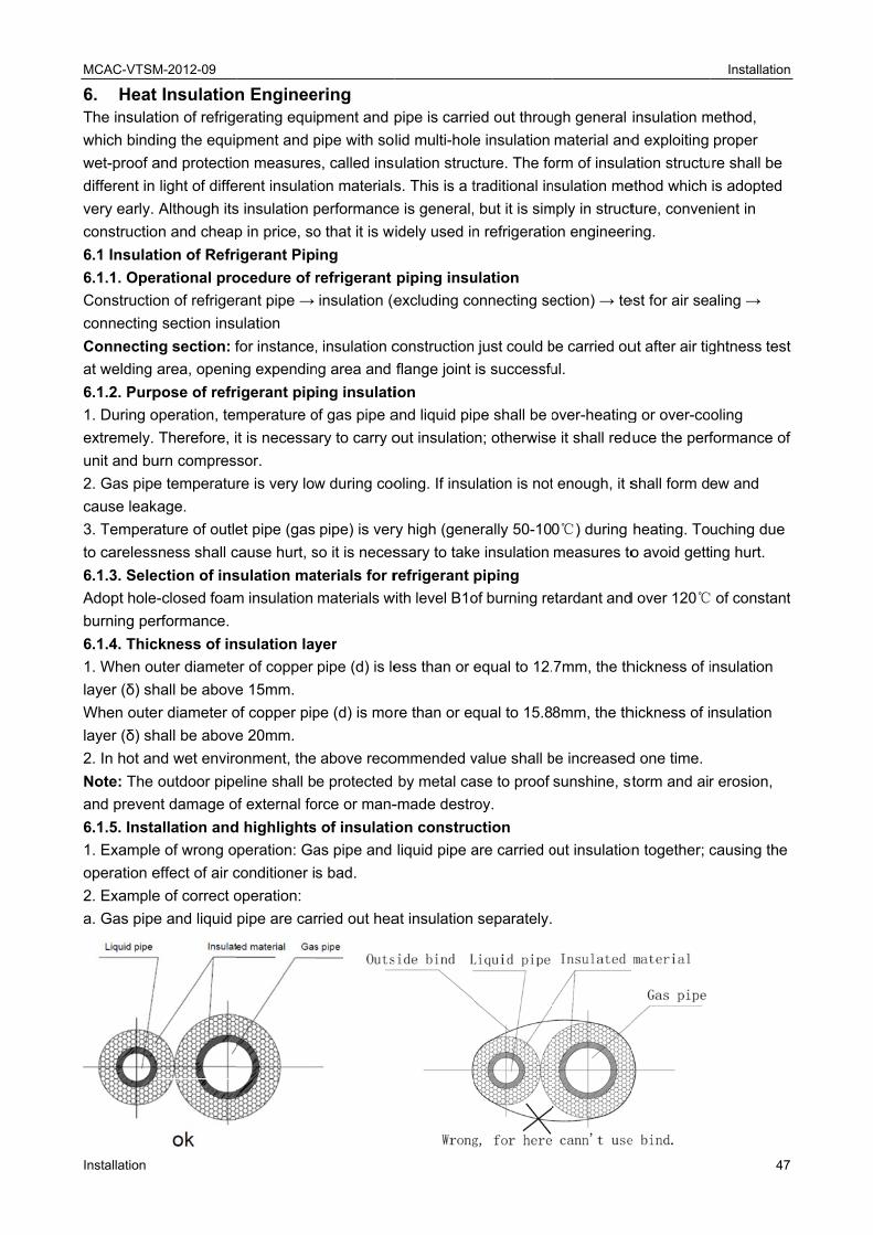
MCAC-VTSM
Installation
6. Heat The insulat
which bindi
wet-proof a
different in
very early.
constructio
6.1 Insulat
6.1.1. Oper
Constructio
connecting
Connectin
at welding a
6.1.2. Purp
1. During o
extremely.
unit and bu
2. Gas pipe
cause leaka
3. Tempera
to careless
6.1.3. Sele
Adopt hole-
burning per
6.1.4. Thic
1. When ou
layer (δ) sh
When oute
layer (δ) sh
2. In hot an
Note: The
and preven
6.1.5. Insta
1. Example
operation e
2. Example
a. Gas pipe
M-2012-09
Insulationtion of refrige
ing the equi
and protectio
light of diffe
Although its
n and cheap
tion of Refr
rational pro
on of refriger
section insu
g section: f
area, openin
pose of refr
operation, te
Therefore, i
urn compres
e temperatu
age.
ature of outle
ness shall c
ction of ins
-closed foam
rformance.
kness of in
uter diamete
hall be above
r diameter o
hall be above
nd wet enviro
outdoor pipe
nt damage o
allation and
e of wrong o
effect of air c
e of correct o
e and liquid
n Engineeerating equi
pment and p
on measures
erent insulati
s insulation p
p in price, so
igerant Pip
ocedure of r
rant pipe →
ulation
for instance,
ng expendin
rigerant pip
mperature o
t is necessa
sor.
re is very low
et pipe (gas
cause hurt, s
sulation ma
m insulation
nsulation lay
er of copper
e 15mm.
of copper pip
e 20mm.
onment, the
eline shall b
of external fo
d highlights
peration: Ga
conditioner i
operation:
pipe are car
ering pment and p
pipe with so
s, called ins
ion materials
performance
o that it is w
ing
refrigerant
insulation (e
, insulation c
ng area and
ing insulati
of gas pipe a
ary to carry o
w during coo
pipe) is ver
so it is neces
aterials for r
materials w
yer
pipe (d) is le
pe (d) is mor
above reco
e protected
orce or man-
s of insulatio
as pipe and
s bad.
rried out hea
pipe is carrie
lid multi-hole
ulation struc
s. This is a t
e is general,
idely used in
piping insu
excluding co
construction
flange joint
ion
and liquid pip
out insulatio
oling. If insu
ry high (gene
ssary to take
refrigerant
with level B1o
ess than or
re than or eq
ommended v
by metal ca
-made destr
on constru
liquid pipe a
at insulation
ed out throu
e insulation
cture. The fo
traditional in
, but it is sim
n refrigeratio
ulation
onnecting se
n just could b
is successfu
pe shall be o
on; otherwise
ulation is not
erally 50-10
e insulation
piping
of burning re
equal to 12.
qual to 15.8
value shall b
ase to proof
roy.
ction
are carried o
separately.
ugh general
material and
orm of insula
nsulation me
mply in struct
on engineeri
ection) → te
be carried ou
ul.
over-heating
e it shall red
t enough, it s
0℃) during
measures to
etardant and
7mm, the th
8mm, the th
be increased
sunshine, st
out insulation
insulation m
d exploiting
ation structu
ethod which
ture, conven
ring.
est for air sea
ut after air tig
g or over-co
uce the perf
shall form d
heating. To
o avoid gett
d over 120℃
hickness of i
hickness of i
d one time.
torm and air
n together; c
Installation
47
method,
proper
re shall be
is adopted
nient in
aling →
ghtness test
oling
formance of
ew and
uching due
ing hurt.
of constant
insulation
nsulation
r erosion,
causing the
n
7
t
f
t
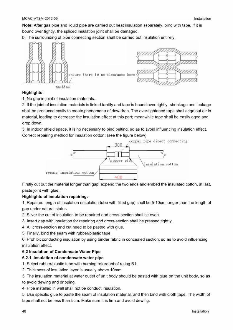
MCAC-VTSM
48
Note: After
bound over
b. The surr
Highlights
1. No gap i
2. If the join
shall be pro
material, le
drop down.
3. In indoor
Correct rep
Firstly cut o
paste joint w
Highlights
1. Repaired
gap under n
2. Sliver the
3. Insert ga
4. All cross
5. Finally, b
6. Prohibit c
insulation e
6.2 Insulat
6.2.1. Insu
1. Select ru
2. Thicknes
3. The insu
to avoid de
4. Pipe inst
5. Use spec
tape shall n
M-2012-09
r gas pipe an
r tightly, the
rounding of p
s:
n joint of ins
nt of insulatio
oduced easi
eading to dec
.
r shield spac
pairing meth
out the mate
with glue.
s of insulatio
d length of in
natural statu
e cut of insu
ap with insul
s-section and
bind the sea
conducting
effect.
tion of Cond
lation of co
ubber/plastic
ss of insulat
ulation mater
ewing and dr
talled in wal
cific glue to
not be less t
nd liquid pip
spliced insu
pipe connec
sulation mat
on materials
ly to create
crease the i
ce, it is no n
od for insula
erial longer th
on repairin
nsulation (in
us.
ulation to be
ation for rep
d cut need to
am with rubb
insulation by
densate Wa
ondensate w
c tube with b
ion layer is u
rial at water
ripping.
l shall not be
paste the se
han 5cm. M
pe are carrie
ulation joint s
cting section
erials.
s is linked ta
phenomena
nsulation eff
ecessary to
ation cotton:
han gap, exp
g:
nsulation tub
repaired an
pairing and c
o be pasted
ber/plastic ta
y using bind
ater Pipe
water pipe
burning retar
usually abov
outlet of un
e conduct in
eam of insul
Make sure it i
ed out heat in
shall be dam
shall be ca
ardily and tap
a of dew-dro
fect at this p
o bind belting
: (see the fig
pend the tw
be with filled
nd cross-sec
cross-sectio
with glue.
ape.
der fabric in c
rdant of ratin
ve 10mm.
it body shou
nsulation.
lation mater
is firm and a
nsulation se
maged.
rried out ins
pe is bound
p. The over-
part; meanw
g, so as to a
gure below)
o ends and
gap) shall b
ction shall be
n shall be p
concealed s
ng B1.
uld be paste
rial, and then
avoid dewing
parately, bin
sulation entir
over tightly,
-tightened ta
hile tape sh
avoid influen
embed the i
be 5-10cm lo
e even.
ressed tight
section, so a
ed with glue
n bind with c
g.
nd with tape
rely.
shrinkage a
ape shall ed
all be easily
cing insulati
insulated co
onger than t
tly.
as to avoid in
on the unit b
cloth tape. T
Installation
Installation
e. If it is
and leakage
ge out air in
y aged and
ion effect.
otton, at last,
he length of
nfluencing
body, so as
The width of
n
e
n
,
f
MCAC-VTSM-2012-09 Installation
Installation 49
6.3 Insulation of Duct
I. Insulation of duct
1. Insulation of duct parts and equipment should be conducted after confirming that the leakage test and
quality of duct is qualified.
2. Usually making use of centrifugal glass cotton, rubber/plastic material or other late-model insulation
duct to conduct insulation.
3. Insulation layer should be even and tight. Crack, gap and other defects are not allowed.
4. The supporting, hanging and mounting bracket of duct should be set up to the outside of insulation
layer, and insert bed timber between bracket and duct.
5. Thickness of insulation layer
1) As for the inlet and outlet duct installed in room free of air conditioner, the thickness of insulation layer
should be above 40mm when adopting centrifugal glass cotton for insulation.
2) As for the inlet and outlet duct installed in room with air conditioner, the thickness of insulation layer
should be above 25mm when adopting centrifugal glass cotton for insulation.
3) When adopting rubber/plastic material and other materials, the thickness of insulation layer should be
come out in accordance with design requirement or calculation.
MCAC-VTSM-2012-09 Installation
50 Installation
7. Electrical Engineering Please refer to “Part 3. Outdoor Units Specification & Performance”.
Highlights of electrical installation
1. Purchased wiring, parts and materials should be in compliance with the local and national
regulations.
2. All field wiring construction should be finished by qualified electrician.
3. Air conditioning equipment should be grounded according to the relevant local and national
electrical regulations.
4. Current leakage protection switch should be installed (select current leakage breaker in light of the
1.5-2 times of total loading rated current.)
5. When connecting wiring and wire holder, use cable clamp to fix and make sure no exposure.
6. Refrigerant piping system and wiring system of indoor and outdoor unit belongs to the different
system.
7. Do not connect the power wire to the terminal of signal wire.
8. When power wire is parallel with signal wire, put wires to their own wire tube and remain proper gap
(the current capacity of power wire is: 10A below 300mm, 50A below 500mm).
9. Voltage discrepancy of power wire terminal (side of power transformer) and end voltage (side of unit)
should be less than 2%. If its length could not be shortened, thicken the power wire. Voltage discrepancy
between phases shall not pass 2% rated value and Current discrepancy between highest and lowest
phase should be less than 3% rated value.
Selection of Wiring
1. The selection of wiring area shall in accordance with the requirements below:
1) Voltage lose of wire shall meet the requirement of terminal voltage for normal operation and startup.
2) The wiring current-carrying capacity determined by installed method and environment is not less
than the largest current of unit.
3) Wiring shall ensure the stability of movement and heating.
4) The smallest sectional area should satisfy the requirement of mechanical strength.
Sectional area of core to phase line S(mm2) Smallest sectional area of PE line (mm2)
S ≤ 16 S
16 < S ≤ 35 16
S > 35 S/2
When earth protection line (shortly called PE line) is made of material the same as phase line, the
smallest sectional area of PE line should be in accordance with the regulation below:
Sectional area of core to phase line S(mm2) Smallest sectional area of PE line (mm2)
Distribution highlights of distribution wiring
1. When distributing wiring, select wirings with different colors for phase line, zero line and protection
earth according to relevant regulations.
2. The power wire and control wire of concealed engineering is prohibited to bind together with
refrigerant piping. It is necessary to pass through wire tube and be distributed separately, and the gap
between control line and power wire should be 500mm at least.
3. When distributing wiring by passing through pipe, the following should be paid attention to:
1) Metal wire tube could be used in indoor and outdoor, but it is not suitable to place with acid - alkali
corrosion.
2) Plastic wire tube is generally used in indoor and place with corrosion, but it is not suitable to
situation with mechanical damage.
3) The wiring through pipe shall not be in the form with ends jointing. If joint is a must, connection box
MCAC-VTSM-2012-09 Installation
Installation 51
should be installed at the corresponding place.
4) The wiring with different voltage should not pass through the same wire tube.
5) Total sectional area of wiring through wire tube shall not exceed 40% valid area of stuffing tube.
6) Fixing point of wire tube support shall follow the standard below:
Nominal diameter of wire tube Largest gap between fixed points of wire tube
(mm) Metal pipe Plastic pipe
15-20 1.5 1
25-32 2 1.5
40-50 2.5 2
Nominal diameter of wire tube Largest gap between fixed points of wire tube
Control System and Installation
Connecting highlights of control line (RS-485 communication)
1. The control line should be shielded wire. Using other wiring shall create signal interference, thus
leading to error operation.
2. Single end to shield net of shielded wire should be grounded.
Note: The shield net should be grounded at the wiring terminal of outdoor unit. The inlet and outlet wire
net of indoor communication wire should be connected directly and could not be grounded, and form
open circuit at the shield net of final indoor unit.
3. Control wire could not be bound together with refrigerant pipeline and power wire. When power wire
and control wire is distributed in parallel form, keep gap between them above 300mm so as to preventing
signal interference.
4. Control wire could not form closed loop.
5. Control wire has polarity, so be careful when connecting.

MCAC-VTSM-2012-09 Installation
52 Installation
8. Commissioning 8.1 Work before Commissioning
8.1.1. Inspection and confirmation before Commissioning
1. Check and confirm that refrigeration pipe line and communication wire with indoor and outdoor unit
have been connected to the same refrigeration system. Otherwise, operation troubles shall happen.
2. Power voltage is within ±10% of rated voltage.
3. Check and confirm that the power wire and control wire are correctly connected.
4. Check whether wire controller is properly connected.
5. Before powering on, confirm there is no short circuit to each line.
6. Check whether all units have passed nitrogen pressure-keeping test for 24 hours with R410A:
40kg/cm2.
7. Confirm whether the system to Commissioning has been carried out vacuum drying and packed with
refrigeration as required.
8.1.2. Preparation before Commissioning
1. Calculating the additional refrigerant quantity for each set of unit according to the actual length of
liquid pipe.
2. Keep required refrigerant ready.
3. Keep system plan, system piping diagram and control wiring diagram ready.
4. Record the setting address code on the system plan.
5. Turn on power switches outdoor unit in advance, and keep connected for above 12 hours so that
heater heating up refrigerant oil in compressor.
6. Turn on gas pipe stop valve, liquid pipe stop valve, oil balance valve and gas balance valve totally. If
the above valves do not be turned on totally, the unit should be damaged.
7. Check whether the power phase sequence of outdoor unit is correct.
8. All dial switches to indoor and outdoor unit have been set according to the Technical Requirement of
Product.
Note: The setting of outdoor unit’s dial switch should be conducted under power-off, otherwise the unit
shall not identify. The following table shows the address and power of outdoor master and slave unit:
ADDRESS dial switch POWER dial switch
0 Master unit 0 8HP
1 Salve unit 1 1 10HP
2 Salve unit 2 2 12HP
3 Salve unit 3 3 14HP
≥4 Invalid address, system
error
4 16HP
/ ≥5 Invalid dial switch
8.2 Commissioning of Trial Run
8.2.1. Commissioning for trail run of single unit.
1. Each independent refrigeration system (i.e. each outdoor unit) should be conducted trail operation.
2. Detection details of trail run:
1) As for fan in unit, make sure the rotating route of its impeller is correct and impeller turns around
smoothly. No abnormal vibration and noise.
2) Check whether there is abnormal noise during operation of refrigerant system and compressor.
3) Check outdoor unit whether it can detect each indoor unit.
4) Check whether drainage is smooth and its lift pump can be in motion.

MCAC-VTSM-2012-09 Installation
Installation 53
5) Check whether microcomputer controller can be in motion normally and whether any trouble appears.
6) Check whether operating current is within the allowed range.
7) Check whether each operating parameter is within the range permitted by the equipment.
Note: When conducting trial run, separately test cooling mode and heating mode to judge the stability
and reliability of system.
8.2.2. Commissioning for the trial run of the paralleled system
1. Check and confirm that operation of single unit is normal through trial operation. After confirm it is
normal, conduct operation of the whole system, i.e., Commissioning of MDV system.
2. Commissioning is carried out according to the Technical Requirement of Product. When
Commissioning, analyze and record operation status so as to understand the operation status of the
whole system for convenient maintenance and examination.
3. After finishing Commissioning, fill out Commissioning report in detail.
The commissioning report form is shown as follows:
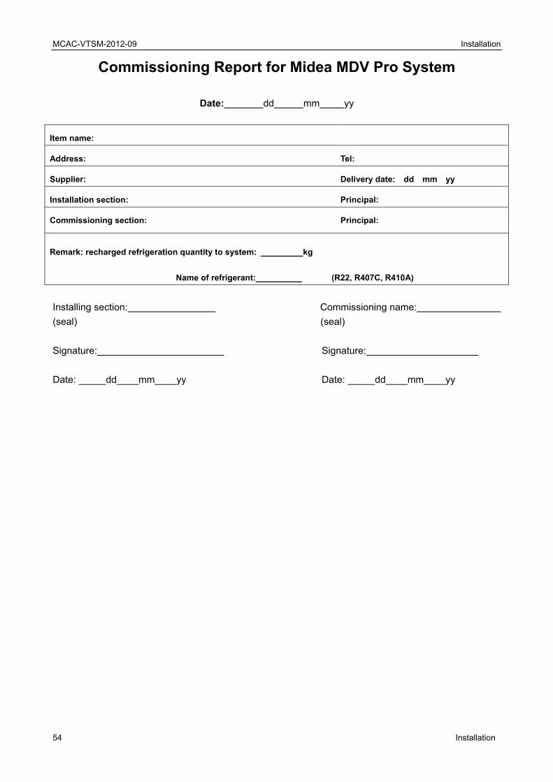
MCAC-VTSM-2012-09 Installation
54 Installation
Commissioning Report for Midea MDV Pro System
Date: dd mm yy
Item name:
Address: Tel:
Supplier: Delivery date: dd mm yy
Installation section: Principal:
Commissioning section: Principal:
Remark: recharged refrigeration quantity to system: kg
Name of refrigerant: (R22, R407C, R410A)
Installing section: Commissioning name:
(seal) (seal)
Signature: Signature:
Date: _____dd____mm____yy Date: _____dd____mm____yy
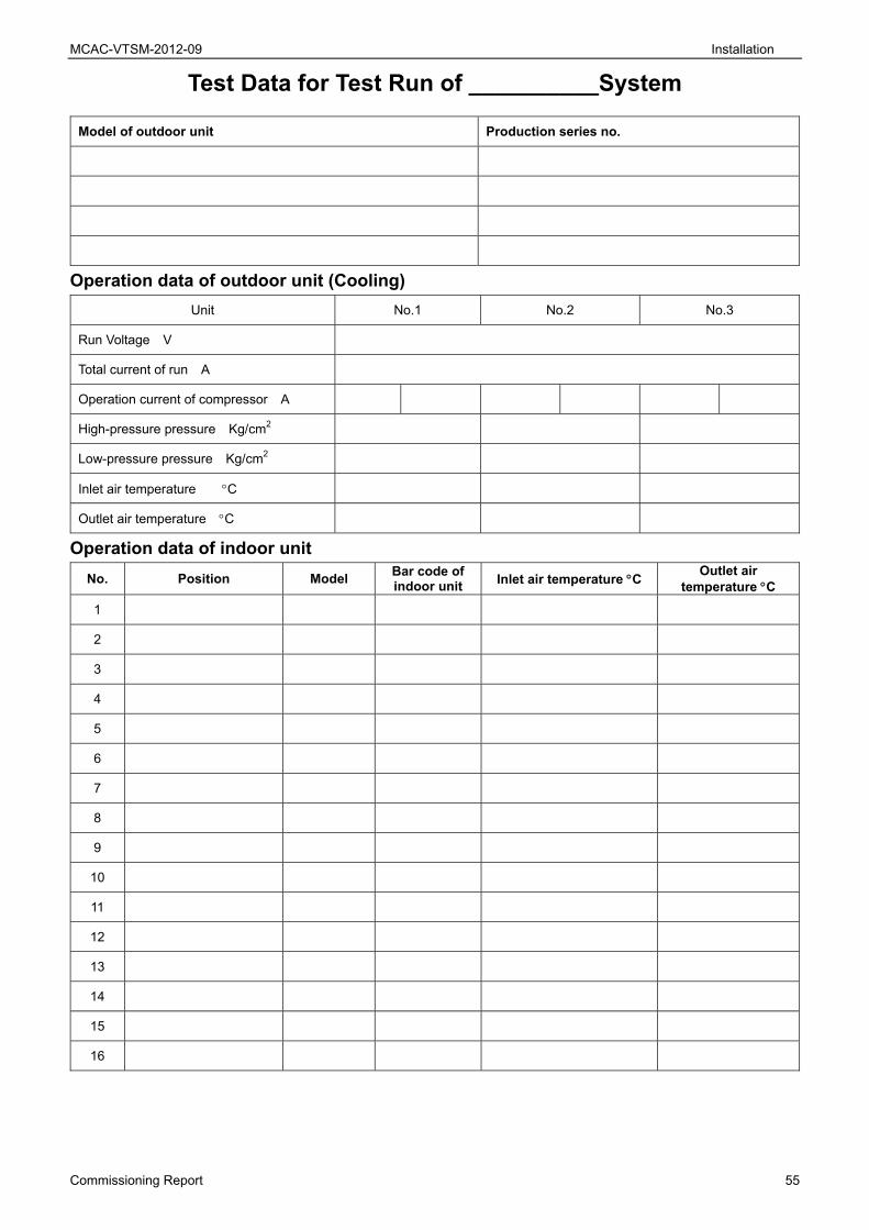
MCAC-VTSM-2012-09 Installation
Commissioning Report 55
Test Data for Test Run of __________System
Model of outdoor unit Production series no.
Operation data of outdoor unit (Cooling)
Unit No.1 No.2 No.3
Run Voltage V
Total current of run A
Operation current of compressor A
High-pressure pressure Kg/cm2
Low-pressure pressure Kg/cm2
Inlet air temperature C
Outlet air temperature C
Operation data of indoor unit
No. Position Model Bar code of indoor unit Inlet air temperature C
Outlet air temperature C
1
2
3
4
5
6
7
8
9
10
11
12
13
14
15
16
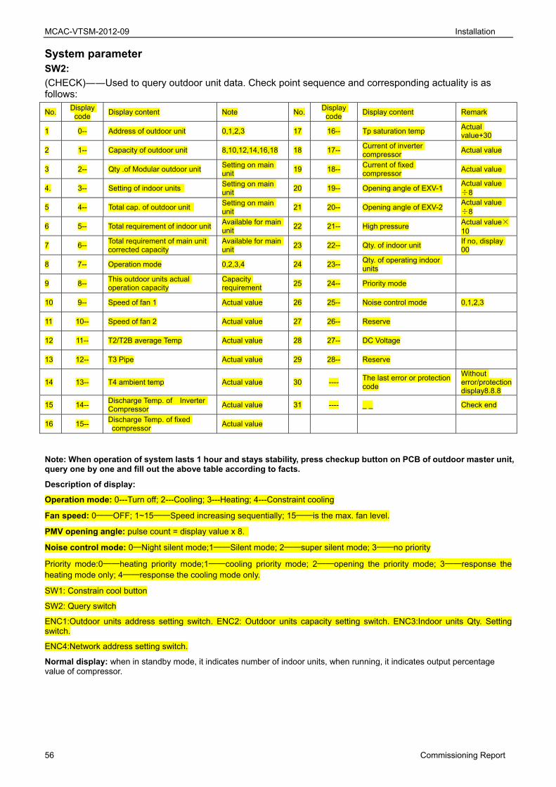
MCAC-VTSM-2012-09 Installation
56 Commissioning Report
System parameter SW2:
(CHECK)――Used to query outdoor unit data. Check point sequence and corresponding actuality is as follows:
No. Display
code Display content Note No.
Display code
Display content Remark
1 0-- Address of outdoor unit 0,1,2,3 17 16-- Tp saturation temp Actual value+30
2 1-- Capacity of outdoor unit 8,10,12,14,16,18 18 17-- Current of inverter compressor
Actual value
3 2-- Qty .of Modular outdoor unit Setting on main unit
19 18-- Current of fixed compressor
Actual value
4. 3-- Setting of indoor units Setting on main unit
20 19-- Opening angle of EXV-1 Actual value ÷8
5 4-- Total cap. of outdoor unit Setting on main unit
21 20-- Opening angle of EXV-2 Actual value ÷8
6 5-- Total requirement of indoor unit Available for main unit
22 21-- High pressure Actual value×10
7 6-- Total requirement of main unit corrected capacity
Available for main unit
23 22-- Qty. of indoor unit If no, display 00
8 7-- Operation mode 0,2,3,4 24 23-- Qty. of operating indoor units
9 8-- This outdoor units actual operation capacity
Capacity requirement
25 24-- Priority mode
10 9-- Speed of fan 1 Actual value 26 25-- Noise control mode 0,1,2,3
11 10-- Speed of fan 2 Actual value 27 26-- Reserve
12 11-- T2/T2B average Temp Actual value 28 27-- DC Voltage
13 12-- T3 Pipe Actual value 29 28-- Reserve
14 13-- T4 ambient temp Actual value 30 ---- The last error or protection code
Without error/protection display8.8.8
15 14-- Discharge Temp. of Inverter Compressor
Actual value 31 ---- _ _ Check end
16 15-- Discharge Temp. of fixed compressor
Actual value
Note: When operation of system lasts 1 hour and stays stability, press checkup button on PCB of outdoor master unit, query one by one and fill out the above table according to facts.
Description of display:
Operation mode: 0---Turn off; 2---Cooling; 3---Heating; 4---Constraint cooling
Fan speed: 0──OFF; 1~15──Speed increasing sequentially; 15──is the max. fan level.
PMV opening angle: pulse count = display value x 8.
Noise control mode: 0─Night silent mode;1──Silent mode; 2──super silent mode; 3──no priority
Priority mode:0──heating priority mode;1──cooling priority mode; 2──opening the priority mode; 3──response the heating mode only; 4──response the cooling mode only.
SW1: Constrain cool button
SW2: Query switch
ENC1:Outdoor units address setting switch. ENC2: Outdoor units capacity setting switch. ENC3:Indoor units Qty. Setting switch.
ENC4:Network address setting switch.
Normal display: when in standby mode, it indicates number of indoor units, when running, it indicates output percentage value of compressor.