part 4 steel & aluminium construction u15m · pdf filepart 4 steel and aluminium...
TRANSCRIPT

PART 4
STEEL AND ALUMINIUM CONSTRUCTION

PART 4 STEEL AND ALUMINIUM CONSTRUCTION SECTION SUBJECT 4.1 Materials 4.2 Main hull construction 4.3 Centre and side girders (bottom construction) 4.4 Bottom construction (floors) 4.5 Integral tanks 4.6 Stem, stern frame and keels 4.7 Bulbous bows and nozzles 4.8 Side framing 4.9 Shell plating 4.10 Deck plating 4.11 Wood deck sheathing 4.12 Deck beams 4.13 Deck girders 4.14 Pillars 4.15 Bulkheads 4.16 Bulwarks 4.17 Bilge keels 4.18 Deckhouses and superstructures 4.19 Shelter decks 4.20 Tables 4.20.1 Keel and stem 4.20.2 Stern frame 4.20.3 Shell plating 4.20.4 Transverse floors 4.20.5 Centre girders 4.20.6 Transverse main frames 4.20.7 Tank top plating 4.20.8 Main deck plating 4.20.9 Deck beams 4.20.10 Deck girders 4.20.11 Pillars 4.20.12 Watertight bulkheads 4.20.13 Bulwark plating and bulwark stays 4.20.14 Chine bars 4.20.15 Shelter deck beams 4.20.16 Shelter deck side plating and stiffeners 4.20.17 Shelter deck plating 4.20.18 Shelter deck girders

PART 4 STEEL AND ALUMINIUM CONSTRUCTION (continued) SECTION SUBJECT 4.21 Figures and illustrations 4.21.1 Scantling numeral dimensions – steel and aluminium vessels 4.21.2 Scantling numeral dimensions – steel and aluminium vessels 4.21.3 Beam knees and longitudinal brackets 4.21.4 Longitudinal girder brackets 4.21.5 Side frame bottom brackets 4.21.6 Bottom construction 4.21.7 Bilge keel details 4.21.8 Longitudinal shell plate stringer position 4.21.9 Typical keel arrangement 4.21.10 Deck girder arrangements 4.21.11 Chine bar


September 2012 Less than 15m LOA Construction Standards
Copyright © Sea Fish Industry Authority 2012 Steel and Aluminium Construction
STEEL AND ALUMINIUM CONSTRUCTION Section 4.1 - Materials Steel plate and sections 4.1.1 Steel is to be manufactured by an approved process in accordance with
Lloyds requirements for shipbuilding quality mild steel, or similar Standards.
4.1.2 Scantlings are based on mild steel with the following properties:- Yield strength (min) 235 N/mm2 Tensile strength 400-490 N/mm2 Modulus of elasticity 200 x 103 N/mm2 4.1.3 Documentation in the form of mill test certificates for hull plating and
main structural members should be available for inspection and identification by the Surveyor.
4.1.4 Steel plate and sections should be stored so that distortion does not
occur and immersion in water is avoided. Aluminium plate and sections 4.1.5 Aluminium alloy plates and sheets for use with these Standards are to be
of marine grade to the requirements of BS 5083/DIN 1725 (or equivalent), with consumables to BS 5356 (or equivalent).
4.1.6 Aluminium sections, where not available to the standard in Paragraph
4.1.5 may be to BS 6082 (or equivalent), with consumables to BS 4043 (or equivalent).
4.1.7 Scantlings are based on marine grade aluminium with the following
properties:- 0.2% proof stress (min) 170 N/mm2 Tensile strength (min) 260 N/mm2 Modulus of elasticity 69 x 103 N/mm2 4.1.8 Plates should be of annealed (flanging quality) material. 4.1.9 Documentation in the form of mill test certificates is to be provided for all
structural aluminium materials. 4.1.10 Aluminium materials are to be stored under cover in clean, dry conditions
and in such a manner that distortion is prevented. The storage area is to be separate from storage of other metals.

September 2012 Less than 15m LOA Construction Standards
Copyright © Sea Fish Industry Authority 2012 Steel and Aluminium Construction
Steel construction 4.1.11 Construction should be carried out in a designated area and where
practicable, protected from adverse wind and weather conditions. 4.1.12 Steel plate and section may be cut by profile burning, mechanical saw,
mechanical shears/guillotine, or other approved process. Cut edges are to be straight and free of scoring, swarf, and burrs. Plate edge preparation is to be carried out prior to erection where possible.
4.1.13 Plate edges are to be carefully aligned to avoid distortion on welding. 4.1.14 Scantlings are to be obtained from the associated Tables shown in
Section 4.20. Aluminium construction 4.1.15 Fabrication and erection of aluminium structures is to be carried out
under cover, screened from wind and weather and where practicable, is to be separate from steel fabricating areas.
4.1.16 Where temperatures below 0C can occur, the fabrication and
construction area is to be heated. Welding is not to be carried out in temperatures of less than 5C.
4.1.17 Plate, sheet, and sections may be cut by plasma process, mechanical
saws, or mechanical shear/guillotine. Such tools are to be free from contamination by other materials. Where plate is to be flanged for pre-forming structural sections, the inside radius is to be a minimum of 1.5 times plate thickness.
4.1.18 All plate edges, and areas to be connected by welding are to be de-
greased with a de-greasing agent, and scratch brushed to remove oxides.
4.1.19 Care is to be taken when connecting together of steel and aluminium
structures or components. Welded connections may be by bi-metallic bar (‘Kelocouple’ or equivalent) or by bolting. Bolted joints are to be insulated between the metals. Bolts are to be stainless steel or plated, and insulated from bi-metallic contact.
4.1.20 Where construction of aluminium superstructures are proposed, details
of scantlings and construction methods are to be submitted for approval prior to commencing construction.

September 2012 Less than 15m LOA Construction Standards
Copyright © Sea Fish Industry Authority 2012 Steel and Aluminium Construction
Section 4.2 - Main hull construction 4.2.1 Minor details of construction based on existing designs, shipyard
standards, and normal practices proposed as an alternative to the following standards, will be considered upon submission of details for consideration.
4.2.2 Where construction is proposed by means of pre-formed or pre-
fabricated kit, drawings showing scantlings and connection assembly procedures are to be submitted for consideration prior to commencing of cutting of kit.
4.2.3 Construction of the hull may be of the round bilge, single, or multi-chine
form. 4.2.4 Scantlings are to be in accordance with the appropriate Section or Table
reference. 4.2.5 Care is to be taken to avoid abrupt changes in the structure of the vessel
(e.g. alignment of engine girders to side girders, tank sides, etc.), but where such changes are unavoidable, adequate compensation is to be incorporated, to the approval of the Surveyor.
4.2.6 Scantlings shown in the Tables are based on transverse framing
construction. 4.2.7 Generally frames, beams, and other stiffeners should be of flat bar, bulb,
or angle section and are to be toe welded. Alternative sections to those specified in the Tables together with modulus calculations confirming equivalent strength to Table requirements, should be submitted for approval.
4.2.8 Longitudinal stiffeners may include stringers, engine seatings, and
chines, subject to approval. 4.2.9 Particular attention is to be given to the stiffening at the ends of the
vessel, and especially in way of areas which may be subjected to slamming.
4.2.10 Adequate access should be arranged to double bottom areas and in way
of tank boundaries to facilitate inspection and testing. Section 4.3 - Centre and side girders (bottom construction) 4.3.1 The centre girder in vessels with a plate keel is to extend over the whole
of the length of the keel, except that in way of the main engine, the side girders forming the engine seatings may be accepted in lieu of the centre girder, subject to the approval of the Surveyor, and provided continuity of strength is maintained. The thickness of vertical plate girders forming engine seats should be at least that required for the centre girder.
September 2012 Less than 15m LOA Construction Standards
Copyright © Sea Fish Industry Authority 2012 Steel and Aluminium Construction
4.3.2 The centre girder and the engine seatings are to overlap by at least one frame space, and are to be tapered to avoid abrupt changes in structure.
4.3.3 When it is proposed to fit side girders in lieu of a centre girder, e.g. in
order to form a duct for the propeller shaft in vessels with a forward engine room, the thickness of the side girders is to be at least that of the adjoining floor.
4.3.4 Where it is proposed that a box keel be fitted, details are to be submitted
for consideration and approval. 4.3.5 Fabricated ballast keels constructed with heavy bars will be specially
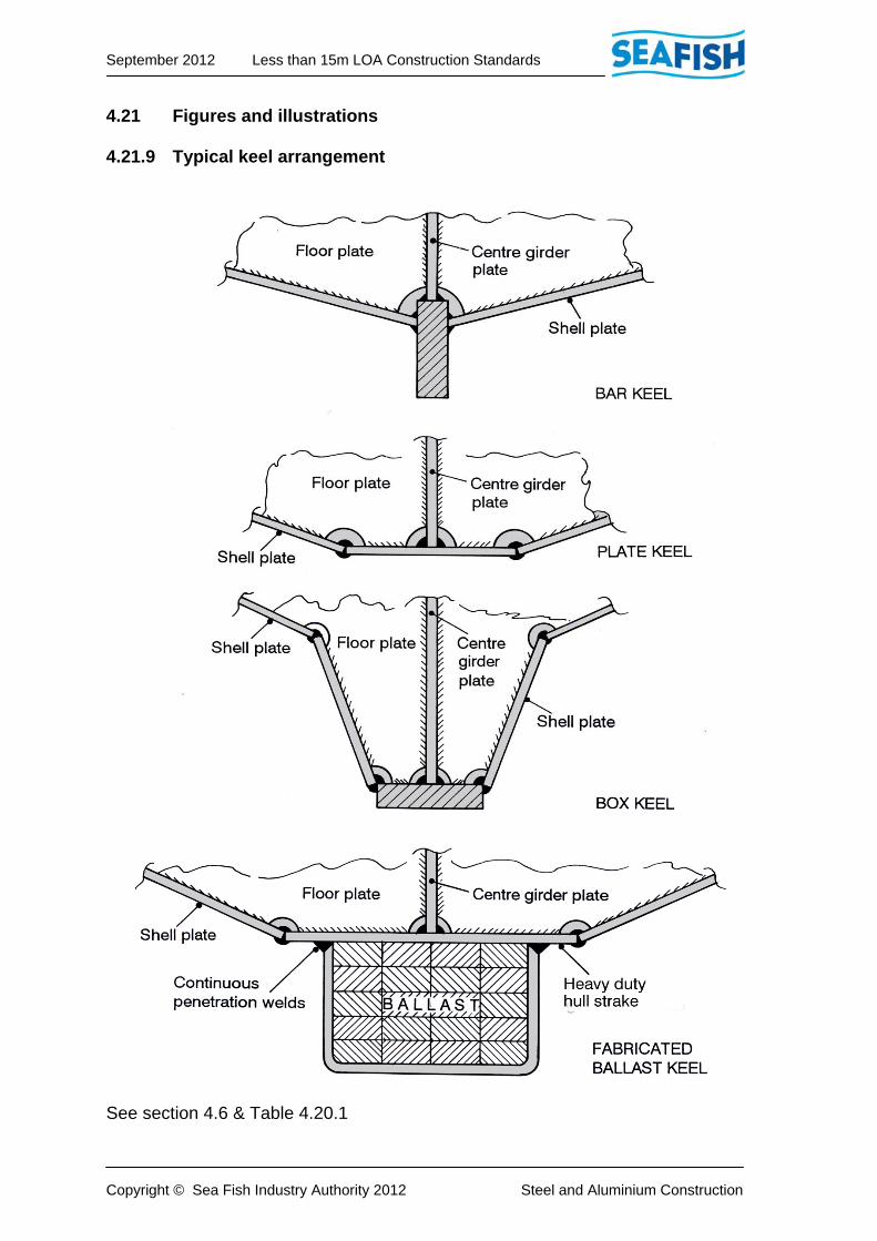
considered after submission of section and welding details prior to construction. See also Figure 4.21.9.
4.3.6 Vessel engine girders are to be extended fore and aft, over two frame
spaces where practicable, and may be tapered down to half the height of the adjoining floor at ends and welded to the adjoining floor. Transverse floors between girders may be reduced in height to suit deep sumps etc., provided substantial fully welded face bars are fitted.
Section 4.4 - Bottom construction (floors) 4.4.1 In longitudinally framed vessels, plate floors are to be fitted at every third
frame station or at a spacing not exceeding 1.5m, whichever is the lesser, and of the height shown in Table 4.20.4.
4.4.2 Plate floors in accordance with Table 4.20.4 are to be fitted at every
transverse frame, and weld connected to the side frames and shell. 4.4.3 Where the rise of floor is excessive, the tops of transverse floors may be
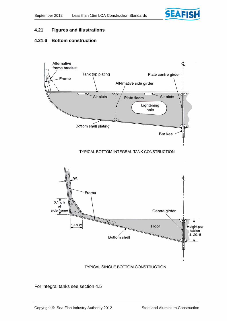
maintained parallel to the height of the centre girder, and the side frames continued at the bottom shell to connect to the floor plates. See Figure 4.21.6.
i) All floors are to be flanged or fitted with a face bar.
ii) All floors are to be welded in accordance with Part 5 of these Standards.
4.4.4 The depth of floors at the centreline is to be not less than that specified
in Table 4.20.4. Where there is a rise of floor, the depth of the floors is to be increased in order that the depth at 25% of the distance between the centreline and the outboard extremity of the floor, is not less that 75% of the required depth of floor at the centreline.
4.4.5 Where twin propulsion engines are to be fitted, details of the proposed
engine seating arrangement are to be submitted for consideration and approval.
September 2012 Less than 15m LOA Construction Standards
Copyright © Sea Fish Industry Authority 2012 Steel and Aluminium Construction
4.4.6 In general, engine seatings are to be formed with longitudinal girders, fully welded to shell plating and transverse floors, and fitted with fully welded substantial top plates. The cross-sectional area of the top plates and vertical girders are to be suitable for the maximum power of the propulsion engine, and are to be approved by the engine Manufacturer/Supplier.
4.4.7 Top plates are to be tapered off at ends, clear of engine and gearbox
holding down bolts over a minimum of one frame space. Abrupt changes in section are to be avoided by tapering the heavier member.
4.4.8 Access holes in girders and floors are to have face bars fitted, where the
distance from shell plate is less than 150mm or the access hole is greater than 300mm x 450mm.
Section 4.5 - Integral tanks 4.5.1 For integral tanks in single bottom vessels, other than deep tanks, the
thickness of the tank top plating is to be not less than that required for tank top plating as shown in Table 4.20.7.
4.5.2 The thickness of other plating forming the boundaries of such tanks
should not be less than that required for the connecting shell plating. 4.5.3 Integral tanks are to be fitted with lightened plate stiffeners which may
form baffles or wash plates at every alternate frame, and are to be of a thickness not less than that required for adjacent plate floors.
4.5.4 Side frames should be connected to tank tops by brackets as for tank top
plating. 4.5.5 Access manholes are to comply with the requirements shown in Part 9,
Paragraph 9.2.11. 4.5.6 Where the depth of the floor exceeds 1m, vertical stiffeners are to be
fitted to plate floors at a spacing not exceeding 1m. 4.5.7 All tanks to be pressure tested to conform fully to section 1.5.4. If it is not
witnessed by a surveyor, a certificate confirming compliance is to be provided for each tank.
Section 4.6 – Stem, stern frame and keels 4.6.1 The stem may be either of the bar or plate type, or a combination of both. 4.6.2 Stern frames are to be fabricated in accordance with scantling
Table 4.20.2 and efficiently attached to the hull structure.
September 2012 Less than 15m LOA Construction Standards
Copyright © Sea Fish Industry Authority 2012 Steel and Aluminium Construction
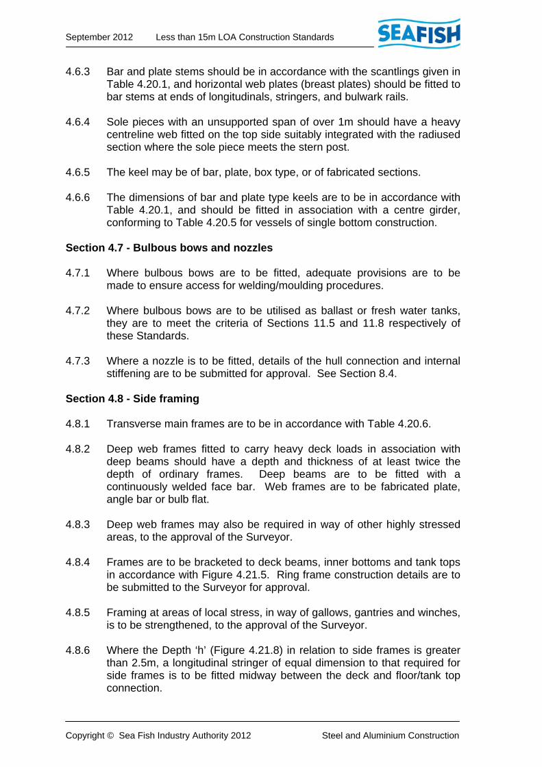
4.6.3 Bar and plate stems should be in accordance with the scantlings given in Table 4.20.1, and horizontal web plates (breast plates) should be fitted to bar stems at ends of longitudinals, stringers, and bulwark rails.
4.6.4 Sole pieces with an unsupported span of over 1m should have a heavy
centreline web fitted on the top side suitably integrated with the radiused section where the sole piece meets the stern post.
4.6.5 The keel may be of bar, plate, box type, or of fabricated sections. 4.6.6 The dimensions of bar and plate type keels are to be in accordance with
Table 4.20.1, and should be fitted in association with a centre girder, conforming to Table 4.20.5 for vessels of single bottom construction.
Section 4.7 - Bulbous bows and nozzles 4.7.1 Where bulbous bows are to be fitted, adequate provisions are to be
made to ensure access for welding/moulding procedures. 4.7.2 Where bulbous bows are to be utilised as ballast or fresh water tanks,
they are to meet the criteria of Sections 11.5 and 11.8 respectively of these Standards.
4.7.3 Where a nozzle is to be fitted, details of the hull connection and internal
stiffening are to be submitted for approval. See Section 8.4. Section 4.8 - Side framing 4.8.1 Transverse main frames are to be in accordance with Table 4.20.6. 4.8.2 Deep web frames fitted to carry heavy deck loads in association with
deep beams should have a depth and thickness of at least twice the depth of ordinary frames. Deep beams are to be fitted with a continuously welded face bar. Web frames are to be fabricated plate, angle bar or bulb flat.
4.8.3 Deep web frames may also be required in way of other highly stressed
areas, to the approval of the Surveyor. 4.8.4 Frames are to be bracketed to deck beams, inner bottoms and tank tops
in accordance with Figure 4.21.5. Ring frame construction details are to be submitted to the Surveyor for approval.
4.8.5 Framing at areas of local stress, in way of gallows, gantries and winches,
is to be strengthened, to the approval of the Surveyor. 4.8.6 Where the Depth ‘h’ (Figure 4.21.8) in relation to side frames is greater
than 2.5m, a longitudinal stringer of equal dimension to that required for side frames is to be fitted midway between the deck and floor/tank top connection.

September 2012 Less than 15m LOA Construction Standards
Copyright © Sea Fish Industry Authority 2012 Steel and Aluminium Construction
4.8.7 End brackets of deep web frames where connected to longitudinal bulkheads or coamings, are to be as those required for deck girders.
4.8.8 At the fore and aft ends of the hull where frames are fitted normal to the
centreline, frames may be canted to provide welding access, with suitable connections to floors and beams.
Section 4.9 - Shell plating 4.9.1 The thickness of shell plating is to be in accordance with Table 4.20.3. 4.9.2 The thickness of the sheerstrake plating is to be increased in accordance
with the Tables in way of areas where excessive wear may occur due to fishing operations. Alternatively, solid section half round bar or convex may be fully welded to the shell plating at these positions.
4.9.3 Chine bars, where fitted, are to be solid round, and of diameter as shown
in Table 4.20.14. 4.9.4 Where the thickness of the shell is to be increased by the use of an
insert, plates are to have a minimum radius of 50mm. 4.9.5 Rubbing bars, where fitted, should be of solid section and are to be
continuously welded to the shell plating. 4.9.6 Butts and seams in shell plating are to be so arranged as to provide a
distance of 100mm from vertical and horizontal framing and structural connections, and in no instance is to exceed 150mm.
4.9.7 Upon completion of fabrication, all weld marks from clips, dogs or other
devices utilised in the fabrication of the vessel including weld spatter are to be removed and repaired where necessary.
Section 4.10 - Deck plating 4.10.1 The thickness of deck plating is to be in accordance with Table 4.20.8. 4.10.2 All openings in deck plating are to be adequately framed and their
corners radiused to a minimum of 50mm. 4.10.3 Deck plating in way of masts, machinery, gantries, and deck loads, etc.,
subject to areas of stress, is to be strengthened, to the approval of the Surveyor.
4.10.4 Plating butts and seams are to be arranged to provide a minimum
distance of 100mm, and in no instance greater than 150mm from beam, girder, and bulkhead connections.

September 2012 Less than 15m LOA Construction Standards
Copyright © Sea Fish Industry Authority 2012 Steel and Aluminium Construction
Section 4.11 - Wood deck sheathing 4.11.1 Wood sheathing, where fitted to the steel deck, is to be of an approved
timber and fitted up to flat bar margins in way of all deck fittings and waterways. The thicknesses of margin bars are to be at least 15% greater than that required for the deck plating. Margin bars are to be welded with a continuous sealing run on one side to prevent water ingress under the sheathing. The fastening of sheathing should not affect integrity or strength of the deck plating, (e.g. not through-fastened).
4.11.2 All wood deck sheathing is to be installed over a suitable bedding
compound to the Surveyor’s approval. Section 4.12 - Deck beams 4.12.1 Deck beams are to be in accordance with Table 4.20.9, fitted and
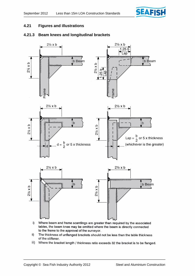
bracketed to each transverse frame. Brackets and beam knees are to be in accordance with Figure 4.21.3 or equivalent.
4.12.2 Beams in way of large deck openings (i.e. greater than 0.2B), and heavy
deck equipment, should be increased in depth by not less than twice the depth of the ordinary beams, as for web frames.
Section 4.13 - Deck girders 4.13.1 Girders are to be in accordance with Table 4.20.10, and end brackets in
accordance with Figure 4.21.4. 4.13.2 In vessels where construction is of the longitudinally framed system,
consideration may be given for the use of longitudinal deck stiffening in conjunction with web frames, subject to the prior submission of details. Such web frames are to be fitted at plate floors as detailed in Paragraph 4.4.1.
4.13.3 Girders are to extend over the full length of the deck, excepting where a
longitudinal bulkhead is fitted at a similar position. 4.13.4 Where deck girders are scalloped for the passage of continuous deck
beams, the depth of the girder is to be twice that of the beam except where welded collars are fitted over beam/girder penetrations See Figure 4.21.10.
4.13.5 Tripping brackets from beam to girder are to be fitted in way of pillars,
and at every third frame space clear of pillars. See Figure 4.21.10. 4.13.6 Where a connection between girders of dissimilar metals is made, an
insulating material is to be fitted between the girders and connected with bolts of compatible material or fitted with insulating ferrules/washers. Alternatively, the joint may be transitioned using a bi-metallic welding strip connection.
September 2012 Less than 15m LOA Construction Standards
Copyright © Sea Fish Industry Authority 2012 Steel and Aluminium Construction
Section 4.14 - Pillars 4.14.1 When the unsupported span of deck girders exceeds 3m, pillars, in
accordance with Table 4.20.11, are to be fitted. Where pillars are to be omitted, web frames providing an equivalent support are to be fitted.
4.14.2 In way of the fish hold, the hold pound stanchions may be accepted as
meeting the requirements of pillars, subject to these being of equivalent section modulus and inertia, and that they are permanently attached to the hull and deck structures.
4.14.3 Details of pillars fitted in way of areas of local stress and heavy deck
equipment, are to be submitted for consideration. 4.14.4 Pillars may be of tubular or hollow square section. 4.14.5 Pillars are to be fitted with brackets to the approval of the Surveyor. 4.14.6 Pillars should be positioned, whenever practicable, at the intersection of
floors and longitudinal structural members at the bottom, and at the intersection of longitudinal deck girders and beams at the top. Where this is not practicable, or where positioned over floor or girder manholes, additional local stiffening is to be fitted to the approval of the Surveyor.
Section 4.15 - Bulkheads 4.15.1 Watertight bulkheads are to be fitted in all vessels as required by Part 3, Section 3.11. 4.15.2 The thickness, spacing, and section modulus of stiffeners for watertight
bulkheads are shown in Table 4.20.12. 4.15.3 Where a bulkhead forms a fore peak or collision bulkhead, the thickness
of the bulkhead plating is to that of the adjoining shell plate. 4.15.4 Watertight bulkheads in decked vessels are to extend to the lowest
continuous deck above the deepest operational waterline. 4.15.5 Pipe or drain penetrations in the collision or fore peak bulkhead are to be
fitted with a valve or cock on the after side, fitted directly to the bulkhead, and arranged to be accessible at all times or fitted with an extended operating spindle to the deck.
4.15.6 Non-watertight bulkheads are to have scantlings as required for
watertight bulkheads.

September 2012 Less than 15m LOA Construction Standards
Copyright © Sea Fish Industry Authority 2012 Steel and Aluminium Construction
Section 4.16 - Bulwarks 4.16.1 On decked or partially decked vessels, the perimeter of the exposed
deck is to be fitted with fixed bulwarks, guardrails or wires, or a combination of these.
4.16.2 The height of the bulwark, guardrail, or wire is to be not less than 1m,
where there is unreasonable interference with efficient operation of the vessel, this height for fixed bulwarks, rails, and wires, may be reduced, and the required height of 1m maintained by the use of portable wires and stanchions. See Section 11.11 and Figure 11.19.1.
4.16.3 Plate bulwarks are to be fitted with a substantial top rail of flat bar, angle,
bulb flat, or other approved section. 4.16.4 Bulwark stays of flat bar or flanged plate are to be fitted at alternate
frames. Thickness of the stays are to be not less than the bulwark plating. Stays should be continuously welded to prevent corrosion. The connection of the stay to the deck are to be over deck beams, but where this is not practicable, the stay may be landed to a welded pad on the deck plating.
4.16.5 Additional bulwark stays are to be fitted in way of gantries or gallows to
the satisfaction of the Surveyor. 4.16.6 Plate thickness of fixed bulwarks is to be determined from Table 4.20.13. 4.16.7 Where tubular guardrails or wires are fitted, the lower course of rails or
wire is to have a clearance of not more than 230mm above the deck, with remaining courses evenly spaced.
4.16.8 Where fishing operations involve the use of openings in bulwarks (e.g. in
way of stern ramps, etc.), details are to be submitted for approval prior to fitting.
Section 4.17 - Bilge keels 4.17.1 Bilge keels are to be of plate, flat bar, or bulb flat, suitably stiffened,
radiused or tapered at ends, and arranged to terminate over an internal frame or stiffener. Bilge keels should not extend beyond the projected vertical line of the side plating at waterline level.
4.17.2 The hull plating is to be reinforced in way of the bilge keel by a welded
flat bar with a thickness of not less than the adjoining shell plate thickness and with a minimum width of 12 times thickness. The flat bar is to be secured to the hull with full continuous fillet weld. Welding of the bilge keel to the flat bar is to be by light continuous fillet. See Figure 4.21.7.

September 2012 Less than 15m LOA Construction Standards
Copyright © Sea Fish Industry Authority 2012 Steel and Aluminium Construction
4.17.3 Bilge keels of an unusual design will be specially considered for approval prior to fitting.
Section 4.18 – Deckhouses and superstructures 4.18.1 In open decked vessels where a raised poop, engine box or casing is
fitted over an engine space, it may be constructed of GRP, timber, steel, or aluminium.
4.18.2 On decked vessels where the wheelhouse and deckhouse is constructed
of steel or aluminium, the thickness of the superstructure plating and stiffening is to be as per the requirements of the weathertight sections in Tables 4.20.15 to 4.20.18.
4.18.3 The joints of aluminium superstructures to steel structures are to be
made by means of continuously welded bi-metallic strip, or by bolting as detailed in Part 4, Paragraph 4.1.19.
4.18.4 Where the superstructure is of timber, it is to be planked with approved
timber or marine grade plywood panels with substantial framing. The top is to be sheathed with glass cloth and resin, or other recognised method of weathertight sealing.
4.18.5 Where the superstructure is of GRP, the laminate and scantlings are to
be as required by Table 6.11.12. Special consideration will be given to laminate weight where it is proposed to omit stiffeners. Where the structure is not moulded as a complete unit, and in deckhouses of composite construction, the connection method details are to be submitted for approval.
4.18.6 Where openings to spaces below the main deck are contained within a
superstructure, the superstructure is to be constructed weathertight, unless such openings are fitted with weathertight closures.
4.18.7 Windows and portlights are to comply with the requirements of Part 3
‘Hull Integrity and Arrangement’. Section 4.19 - Shelter decks 4.19.1 On vessels fitted with steel or aluminium weathertight, non-weathertight,
or partial shelter decks above the main or freeboard deck, the shelter deck plating sides, and associated stiffeners, are to be determined from Tables 4.20.15 to 4.20.18.
4.19.2 The shelter height is to be sufficient to provide adequate headroom but
must not obscure all round vision from the steering/navigation position. 4.19.3 Full shelters are defined as those structures whose length extends from
the stem to the stern and whose width extends across the breadth of the vessel, rail to rail.
September 2012 Less than 15m LOA Construction Standards
Copyright © Sea Fish Industry Authority 2012 Steel and Aluminium Construction
4.19.4 The joints of aluminium superstructures to steel structures are to be made by means of continuously welded bi-metallic strip, or by bolting as detailed in Part 4, Paragraph 4.1.20.
4.19.5 Where the shelter is to be included in the vessel’s intact stability, it is to
be constructed weathertight (WT) as an enclosed superstructure, fitted with approved weathertight doors, hatches, and a means of draining the enclosed deck space. Such drains are to incorporate suitable non-return arrangements if draining directly overboard.
4.19.6 Non-weathertight (NWT) shelters (which may extend full breadth over
part or the whole of a vessel’s length) are to be fitted with freeing ports as defined in Section 3.10, and may be left open at either end. It is recommended that closing doors be fitted in way of openings.
4.19.7 Decks and shelter tops in way of masts, derricks, machinery and other
areas of additional deck loading, are to be strengthened with web frames or deep beams and pillars to the approval of the Surveyor.
4.19.8 Pillars are to be fitted such that the unsupported span of the shelter deck
girder does not exceed 3m. Pillars or equivalent support is to be fitted in way of other areas subjected to additional loading.
4.19.9 Rails and stanchions should be fitted to the tops of shelters and in way of
all loading hatches. The top rail is to be 1m above the deck, with the lower rail not more than 230mm above the deck, and mid rail equally spaced between upper and lower rail.
4.19.10 Gutting hatches or ports, and offal chutes fitted in weathertight shelter
sides should have a minimum inboard opening height of 1m and fitted with suitable closing arrangements.
4.19.11 The shelter top is to have a non-slip surface. 4.19.12 In the case of vessels fitted with an enclosed shelter, an additional
access from within to the shelter top should be fitted to facilitate escape in an emergency.

September 2012 Less than 15m LOA Construction Standards
Copyright © Sea Fish Industry Authority 2012 Steel and Aluminium Construction
Section 4.20 - Scantlings tables
Throughout the Tables the letters L, B, and D represent the measurements as shown in Figures 4.21.1, and 4.21.2.
The scantling numeral is the product obtained by multiplying the length L, by breadth B, by depth D, as shown in the Figure. In determining scantlings from the Tables in respect of intermediate lengths, breadths and depths, the scantling applicable is to be that given for the next lower dimension, unless stated otherwise in the Table notes. Where these Tables indicate plate thicknesses and scantlings of sections which are not commercially available, the next higher available thickness or scantling is to apply. In such cases the increased section modulus may be considered in determination of main scantlings. Details of any alternative sections proposed are to be submitted for consideration.
Section 4.21 - Figures and illustrations
Illustrations shown in Figures 4.21.3 through to 4.21.11 are for guidance only. Alternative proposals to those shown may be accepted to the approval of the Surveyor.
September 2012 Less than 15m LOA Construction Standards
Copyright © Sea Fish Industry Authority 2012 Steel and Aluminium Construction
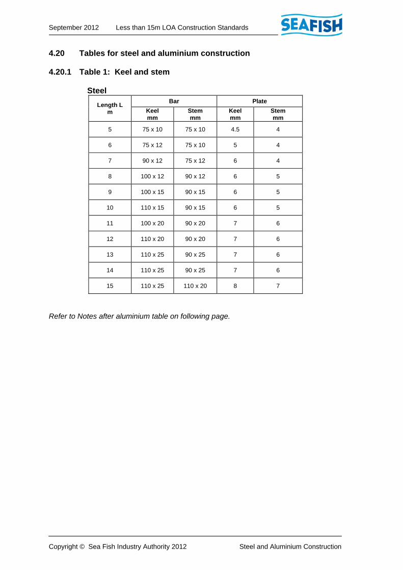
4.20 Tables for steel and aluminium construction 4.20.1 Table 1: Keel and stem Steel
Length L m
Bar Plate
Keel mm
Stemmm
Keelmm
Stem mm
5 75 x 10 75 x 10 4.5 4
6 75 x 12 75 x 10 5 4
7 90 x 12 75 x 12 6 4
8 100 x 12 90 x 12 6 5
9 100 x 15 90 x 15 6 5
10 110 x 15 90 x 15 6 5
11 100 x 20 90 x 20 7 6
12 110 x 20 90 x 20 7 6
13 110 x 25 90 x 25 7 6
14 110 x 25 90 x 25 7 6
15 110 x 25 110 x 20 8 7
Refer to Notes after aluminium table on following page.

September 2012 Less than 15m LOA Construction Standards
Copyright © Sea Fish Industry Authority 2012 Steel and Aluminium Construction
4.20 Tables for steel and aluminium construction 4.20.1 Table 1: Keel and stem (continued) Aluminium
Length L m
Bar Plate
Keelmm
Stemmm
Keelmm
Stem mm
5 88.9 x 12.7 88.9 x 12.7 6 5
6 101.6 x 15.9 80 x 15.9 6.4 5
7 101.6 x 19.1 80 x 19.1 8 5
8 101.6 x 25.4 90 x 25.4 8 6.4
9 101.6 x 25.4 95 x 25.4 8 6.4
10 152.4 x 19.1 110 x 19.1 8 6.4
11 152.4 x 25.4 110 x 25.4 9.5 8
12 152.4 x 25.4 110 x 25.4 9.5 8
13 152.4 x 25.4 120 x 25.4 9.5 8
14 152.4 x 25.4 120 x 25.4 9.5 8
15 152.4 x 25.4 130 x 25.4 10 9
Notes:- 1. Bar keels should be continued to include the fore foot, and the reduction in
scantling from the keel to the stem is to be tapered over a length of not less than 500mm.
2. Where stems are constructed of a combination of bar and plate, the stem bar may be continued at a reduced cross-section to the stem-head. The reduction in section should be tapered as in Note 1 above.
3. The minimum width of plate keels shown in the Table are at amidships and may be tapered at ends to suit the stem plate or bar, and stern skeg.
4. Details of fabricated ballast and box type keels are to be submitted for consideration and approval prior to construction.

September 2012 Less than 15m LOA Construction Standards
Copyright © Sea Fish Industry Authority 2012 Steel and Aluminium Construction
4.20 Tables for steel and aluminium construction 4.20.2 Table 2: Stern frame Steel
Length L m
Stern post Stern bar Sole piece
Minimum sectional
area cm2
Minimum thickness
mm
Minimumsectional
area cm2
Minimum thickness
mm
Minimum sectional
area cm2
7 14 15 6 8 12
8 16 18 9 12 19
9 20 20 12 15 25
10 25 25 15 18 31
11 30 30 20 20 37
12 40 35 25 20 43
13 48 40 30 20 45
14 56 40 32 25 56
15 64 50 38 25 65
Aluminium
Length L m
Stern post Stern bar Sole piece
Minimum sectional
area cm2
Minimum thickness
mm
Minimumsectional
area cm2
Minimum thickness
mm
Minimum sectional
area cm2
7 24 19.1 11 10 21
8 28 25 16 15 33
9 34 25 21 19.1 43
10 43 38.1 26 25 53
11 51 38.1 34 25 63
12 68 44.5 43 25 74
13 82 50.8 51 25 77
14 96 50.8 55 38.1 96
15 109 63.5 65 38.1 111
Refer to Notes on following page.

September 2012 Less than 15m LOA Construction Standards
Copyright © Sea Fish Industry Authority 2012 Steel and Aluminium Construction
4.20 Tables for steel and aluminium construction 4.20.2 Table 2: Stern frame (continued) Notes:- 1. The above scantlings relate to a stern frame supported by plating on both
sides. Where a single plate skeg is fitted, the minimum sectional area and thickness of the stern post is to be increased by 50%.
2. The sole piece may be of solid square, rectangular or T section.
3. The stern frame should be suitably radiused or bracketed where the stern post meets the sole piece.
4. The stern tube housing boss is to have a finished thickness of metal around the bore of at least 30% of the propeller shaft diameter.
5. For vessel with a length scantling L below 7m, details of the stern construction are to be submitted for approval.
6. Solid round sections, where used, are to be of equivalent cross-sectional area to those shown in the Table.

September 2012 Less than 15m LOA Construction Standards
Copyright © Sea Fish Industry Authority 2012 Steel and Aluminium Construction
4.20 Tables for steel and aluminium construction 4.20.3 Table 3: Shell plating
Length L m
Shell thicknessmm
Steel Aluminium
5 3.5 5
6 3.5 5
7 4 5
8 4.5 6
9 5 6.4
10 5 6.4
11 6 8
12 6 8
13 6 8
14 6 8
15 6 8
Notes:- 1. The plate thickness in the above Table are based on a transverse frame
spacing of 500mm for 0.7L amidships. Where the actual frame spacing differs, the thickness of the shell plating is to be increased at the rate of 0.5mm per 50mm of increase in the spacing, unless otherwise approved by the Surveyor.
2. The transom plating of stern fishing vessels is to be increased by at least 1mm above the Table thicknesses shown.
3. Side plating in way of gantries and gallows is to be locally reinforced to the Surveyor’s satisfaction.

September 2012 Less than 15m LOA Construction Standards
Copyright © Sea Fish Industry Authority 2012 Steel and Aluminium Construction
4.20 Tables for steel and aluminium construction
4.20.4 Table 4: Transverse floors Steel
Depth D m
Floors Face bars
mm Minimum depth at centreline and
thickness mm
0.75 150 x 4.5 35 x 4.5
1 160 x 5 35 x 5
1.25 180 x 5 40 x 5
1.5 200 x 5 45 x 5
1.75 230 x 5 50 x 5
2 250 x 6 50 x 6
2.25 280 x 6 50 x 6
2.5 310 x 7 50 x 8
2.75 340 x 7 65 x 8
3 380 x 7 75 x 8
3.25 400 x 8 75 x 8
3.5 440 x 8 75 x 8
3.75 470 x 8 80 x 8
4 500 x 8 80 x 8
Refer to Notes after aluminium table on following page.
September 2012 Less than 15m LOA Construction Standards
Copyright © Sea Fish Industry Authority 2012 Steel and Aluminium Construction
4.20 Tables for steel and aluminium construction
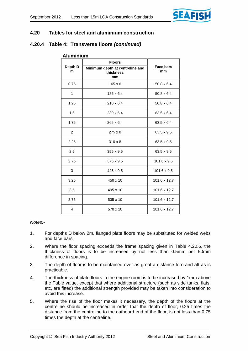
4.20.4 Table 4: Transverse floors (continued) Aluminium
Depth D m
Floors Face bars
mm Minimum depth at centreline and
thickness mm
0.75 165 x 6 50.8 x 6.4
1 185 x 6.4 50.8 x 6.4
1.25 210 x 6.4 50.8 x 6.4
1.5 230 x 6.4 63.5 x 6.4
1.75 265 x 6.4 63.5 x 6.4
2 275 x 8 63.5 x 9.5
2.25 310 x 8 63.5 x 9.5
2.5 355 x 9.5 63.5 x 9.5
2.75 375 x 9.5 101.6 x 9.5
3 425 x 9.5 101.6 x 9.5
3.25 450 x 10 101.6 x 12.7
3.5 495 x 10 101.6 x 12.7
3.75 535 x 10 101.6 x 12.7
4 570 x 10 101.6 x 12.7
Notes:- 1. For depths D below 2m, flanged plate floors may be substituted for welded webs
and face bars.
2. Where the floor spacing exceeds the frame spacing given in Table 4.20.6, the thickness of floors is to be increased by not less than 0.5mm per 50mm difference in spacing.
3. The depth of floor is to be maintained over as great a distance fore and aft as is practicable.
4. The thickness of plate floors in the engine room is to be increased by 1mm above the Table value, except that where additional structure (such as side tanks, flats, etc, are fitted) the additional strength provided may be taken into consideration to avoid this increase.
5. Where the rise of the floor makes it necessary, the depth of the floors at the centreline should be increased in order that the depth of floor, 0.25 times the distance from the centreline to the outboard end of the floor, is not less than 0.75 times the depth at the centreline.
September 2012 Less than 15m LOA Construction Standards
Copyright © Sea Fish Industry Authority 2012 Steel and Aluminium Construction
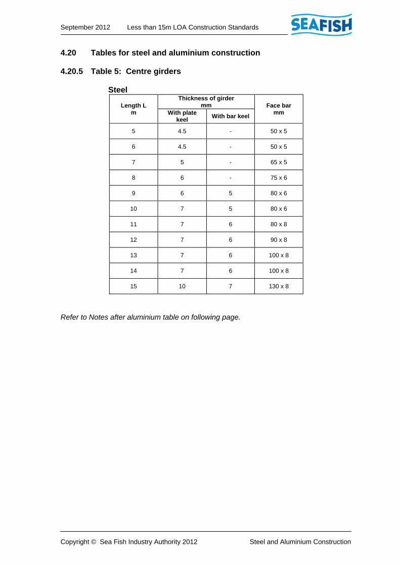
4.20 Tables for steel and aluminium construction 4.20.5 Table 5: Centre girders Steel
Length L m
Thickness of girdermm Face bar
mm With plate keel
With bar keel
5 4.5 - 50 x 5
6 4.5 - 50 x 5
7 5 - 65 x 5
8 6 - 75 x 6
9 6 5 80 x 6
10 7 5 80 x 6
11 7 6 80 x 8
12 7 6 90 x 8
13 7 6 100 x 8
14 7 6 100 x 8
15 10 7 130 x 8
Refer to Notes after aluminium table on following page.
September 2012 Less than 15m LOA Construction Standards
Copyright © Sea Fish Industry Authority 2012 Steel and Aluminium Construction
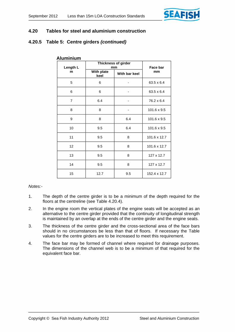
4.20 Tables for steel and aluminium construction 4.20.5 Table 5: Centre girders (continued) Aluminium
Length L m
Thickness of girdermm Face bar
mm With plate keel
With bar keel
5 6 - 63.5 x 6.4
6 6 - 63.5 x 6.4
7 6.4 - 76.2 x 6.4
8 8 - 101.6 x 9.5
9 8 6.4 101.6 x 9.5
10 9.5 6.4 101.6 x 9.5
11 9.5 8 101.6 x 12.7
12 9.5 8 101.6 x 12.7
13 9.5 8 127 x 12.7
14 9.5 8 127 x 12.7
15 12.7 9.5 152.4 x 12.7
Notes:- 1. The depth of the centre girder is to be a minimum of the depth required for the
floors at the centreline (see Table 4.20.4).
2. In the engine room the vertical plates of the engine seats will be accepted as an alternative to the centre girder provided that the continuity of longitudinal strength is maintained by an overlap at the ends of the centre girder and the engine seats.
3. The thickness of the centre girder and the cross-sectional area of the face bars should in no circumstances be less than that of floors. If necessary the Table values for the centre girders are to be increased to meet this requirement.
4. The face bar may be formed of channel where required for drainage purposes. The dimensions of the channel web is to be a minimum of that required for the equivalent face bar.

September 2012 Less than 15m LOA Construction Standards
Copyright © Sea Fish Industry Authority 2012 Steel and Aluminium Construction
4.20 Tables for steel and aluminium construction 4.20.6 Table 6: Transverse main frames Steel
4
3.5
3
2.5
2
1.5
1
0.7
5
Depth D in metres
40
x 40
x 4
60
x 5 F
B
( 5 )
I/Y 5.6
-
60
x 5 F
B
( 5 )
I/Y 4.9
-
50
x 5 F
B
( 4.5
)
I/Y 4.2
-
50
x 5 F
B
( 4.5
)
I/Y 4.0
0.7
5
Len
gth
h in
metres
40
x 40
x 4
65 x 6 FB
( 5 )
I/Y 8.0
-
65 x 5 FB
( 5 )
I/Y 7.1
-
60 x 5 FB
( 5 )
I/Y 6.2
An
gle
Flat B
ar
( Sh
ell th
ickne
ss )
I/Y
1
50
x 40
x 6
75 x 8 FB
( 7 )
I/Y 14
.8
50
x 40
x 6
75 x 8 FB
( 7 )
I/Y 13
.9
50
x 40
x 5
70 x 8 FB
( 6 )
I/Y 12
.8
50
x 40
x 5
70 x 8 FB
( 6 )
I/Y 11
.8
40
x 40
x 6
75 x 6 FB
( 5 )
I/Y 10
.6
-
75 x 6 FB
( 5 )
I/Y 9.3
1.2
5
50
x 50
x 8
90 x 8 FB
( 7 )
I/Y 19
.4
50
x 50
x 6
90 x 8 FB
( 7 )
I/Y 18
.1
50
x 50
x 6
80 x 8 FB
( 6 )
I/Y 16
.7
60
x 30
x 6
75 x 8 FB
( 6 )
I/Y 15
.2
60
x 30
x 5
75 x 8 FB
( 6 )
I/Y 13
.6
50
x 40
x 5
70 x 8 FB
( 5 )
I/Y 11
.9
1.5
65
x 50
x 6
10
0 x 8
FB
( 8 )
I/Y 24
.2
65
x 50
x 6
10
0 x 8
FB
( 7 )
I/Y 22
.4
60
x 50
x 6
90 x 8 FB
( 7 )
I/Y 20
.6
50
x 50
x 8
90 x 8 FB
( 7 )
I/Y 18
.7
50
x 50
x 6
80 x 8 FB
( 6 )
I/Y 16
.7
1.7
5
75
x 50
x 6
10
0 x 1
0 FB
( 8 )
I/Y 29
.8
75
x 50
x 6
10
0 x 1
0 FB
( 7 )
I/Y 27
.6
60
x 50
x 6
10
0 x 8
FB
( 7 )
I/Y 25
.2
65
x 50
x 6
10
0 x 8
FB
( 7 )
I/Y 22
.8
60
x 50
x 6
90 x 8 FB
( 7 )
I/Y 20
.2
2
80
x 60
x 6
11
0 x 1
0 FB
( 8 )
I/Y 36
.0
60
x 60
x 8
10
0 x 1
0 FB
( 8 )
I/Y 33
.4
75
x 50
x 6
10
0 x 1
0 FB
( 7 )
I/Y 30
.6
75
x 50
x 6
10
0 x 1
0 FB
( 7 )
I/Y 27
.6
2.2
5
80
x 60
x 6
12
0 x 1
0 FB
( 8 )
I/Y 43
.4
75
x 75
x 6
11
0 x 1
0 FB
( 8 )
I/Y 40
.2
75
x 50
x 8
11
0 x 1
0 FB
( 8 )
I/Y 36
.8
60
x 60
x 8
10
0 x 1
0 FB
( 8 )
I/Y 33
.2
2.5
75
x 75
x 8
13
0 x 1
2 FB
( 8 )
I/Y 51
.1
80
x 60
x 6
11
0 x 1
2 FB
( 8 )
I/Y 48
.0
70
x 70
x 8
12
0 x 1
0 FB
( 8 )
I/Y 43
.8
2.7
5
10
0 x 6
5 x 7
13
0 x 1
2 FB
( 8 )
I/Y 60
.7
10
0 x 5
0 x 8
12
0 x 1
2 FB
( 8 )
I/Y 56
.4
75
x 75
x 8
12
0 x 1
2 FB
( 8 )
I/Y 51
.6
3
Refer to Notes after aluminium table on following page.

September 2012 Less than 15m LOA Construction Standards
Copyright © Sea Fish Industry Authority 2012 Steel and Aluminium Construction
4.20 Tables for steel and aluminium construction 4.20.6 Table 6: Transverse main frames (continued) Aluminium
4
3.5
3
2.5
2
1.5
1
0.7
5
Depth D in metres
-
76
.2 x 6.4
FB
( 6.4
)
I/Y 9.6
-
63
.5 x 6.4
FB
( 6.4
)
I/Y 8.4
-
63
.5 x 6.4
FB
( 6 )
I/Y 7.2
-
63
.5 x 6.4
FB
( 6 )
I/Y 6.8
0.7
5
Len
gth
h in
metres
-
76
.2 x 9.5
FB
( 6.4
)
I/Y 13
.6
-
76
.2 x 6.4
FB
( 6.4
)
I/Y 12
.1
-
76
.2 x 6.4
FB
( 6.4
)
I/Y 10
.6
An
gle
Flat B
ar
( Sh
ell th
ickne
ss )
I/Y
1
63
.5 x 50.8
x 6.4
76
.2 x 12.7
FB
( 9.5
)
I/Y 25
.2
63
.5 x 50.8
x 6.4
76
.2 x 12.7
FB
( 9.5
)
I/Y 23
.7
63
.5 x 50.8
x 6.4
76
.2 x 12.7
FB
( 8 )
I/Y 21
.8
63
.5 x 38.1
x 6.4
76
.2 x 12.7
FB
( 8 )
I/Y 20
.1
63
.5 x 38.1
x 6.4
76
.2 x 9.5
FB
( 6.4
)
I/Y 18
.1
-
76
.2 x 9.5
FB
( 6.4
)
I/Y 15
.9
1.2
5
76
.2 x 50.8
x 6.4
88
.9 x 12.7
FB
( 9.5
)
I/Y 33
.0
76
.2 x 50.8
x 6.4
10
1.6
x 9.5
FB
( 9.5
)
I/Y 30
.8
76
.2 x 50.8
x 6.4
10
1.6
x 9.5
FB
( 8 )
I/Y 28
.4
76
.2 x 50.8
x 6.4
10
1.6
x 9.5
FB
( 8 )
I/Y 25
.9
63
.5 x 50.8
x 6.4
76
.2 x 12.7
FB
( 8.0
)
I/Y 23
.2
63
.5 x 38.1
x 6.4
76
.2 x 12.7
FB
( 6.4
)
I/Y 20
.3
1.5
76
.2 x 76.2
x 6.4
-
( 10
)
I/Y 41
.2
76
.2 x 76.2
x 6.4
10
1.6
x 12
.7 F
B
( 9.5
)
I/Y 38
.1
76
.2 x 76.2
x 6.4
88
.9 x 12.7
FB
( 9.5
)
I/Y 35
.1
76
.2 x 50.8
x 6.4
10
1.6
x 9.5
FB
( 9.5
)
I/Y 31
.8
76
.2 x 50.8
x 6.4
10
1.6
x 9.5
FB
( 8 )
I/Y 28
.4
1.7
5
10
1.6
x 50
.8 x 6.4
-
( 10
)
I/Y 50
.7
10
1.6
x 50
.8 x 6.4
10
1.6
x 15
.9 F
B
( 9.5
)
I/Y 47
.0
76
.2 x 76.2
x 6.4
10
1.6
x 12
.7 F
B
( 9.5
)
I/Y 42
.9
76
.2 x 76.2
x 6.4
10
1.6
x 12
.7 F
B
( 9.5
)
I/Y 38
.8
76
.2 x 50.8
x 6.4
88
.9 x 12.7
FB
( 9.5
)
I/Y 34
.4
2
10
1.6
x 76
.2 x 6.4
-
( 10
)
I/Y 61
.2
10
1.6
x 76
.2 x 6.4
-
( 10
)
I/Y 56
.8
10
1.6
x 76
.2 x 6.4
10
1.6
x 15
.9 F
B
( 9.5
)
I/Y 52
.1
10
1.6
x 50
.8 x 6.4
10
1.6
x 15
.9 F
B
( 9.5
)
I/Y 47
.0
2.2
5
10
1.6
x101
.6 x 6
.4
-
( 10
)
I/Y 73
.8
10
1.6
x101
.6 x 6
.4
-
( 10
)
I/Y 68
.4
10
1.6
x 76
.2 x 6.4
-
( 10
)
I/Y 62
.6
10
1.6
x 76
.2 x 6.4
-
( 10
)
I/Y 56
.5
2.5
88
.9 x 88.9
x 9.5
-
( 10
)
I/Y 86
.9
10
1.6
x101
.6 x 6
.4
-
( 10
)
I/Y 81
.6
10
1.6
x101
.6 x 6
.4
-
( 10
)
I/Y 74
.5
2.7
5
10
1.6
x101
.6 x 9
.5
-
( 10
)
I/Y 10
3.2
10
1.6
x101
.6 x 9
.5
-
( 10
)
I/Y 95
.9
88
.9 x 88.9
x 9.5
-
( 10
)
I/Y 87
.8
3
Refer to Notes on following page.
September 2012 Less than 15m LOA Construction Standards
Copyright © Sea Fish Industry Authority 2012 Steel and Aluminium Construction
4.20 Tables for steel and aluminium construction 4.20.6 Table 6: Transverse main frames (continued) Notes:- 1. Sections stated are those stock sizes produced equivalent to or greater than the
section moduli given.
2. Section dimensions are in mm and section moduli are in cm3.
3. The section sizes in the Table may be varied provided the relevant section modulus is not reduced.
4. The section moduli are calculated with attached shell plating of thicknesses given in brackets immediately following the section dimension and a frame spacing of 500mm. Where the actual spacing is varied, the section modulus is to be increased or decreased in direct proportion, but in no circumstances should the frame spacing exceed 650mm.
5. Length ‘h’ in the Table is vertical depth of the frame measured from the top of the frame floor or inner bottom to the top of the deck beam at side as shown in Figure 4.21.2.
6. Where frames of T section are used, the section moduli given in the Table may be reduced by 10%.
7. Where alternative flat bar or fabricated frames are proposed in place of rolled section, details are to be submitted for approval prior to utilisation in construction.
September 2012 Less than 15m LOA Construction Standards
Copyright © Sea Fish Industry Authority 2012 Steel and Aluminium Construction
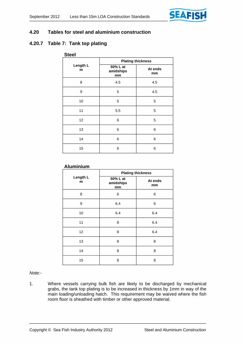
4.20 Tables for steel and aluminium construction 4.20.7 Table 7: Tank top plating Steel
Length L m
Plating thickness
50% L atamidships
mm
At ends mm
8 4.5 4.5
9 5 4.5
10 5 5
11 5.5 5
12 6 5
13 6 6
14 6 6
15 6 6
Aluminium
Length L m
Plating thickness
50% L atamidships
mm
At ends mm
8 6 6
9 6.4 6
10 6.4 6.4
11 8 6.4
12 8 6.4
13 8 8
14 8 8
15 8 8
Note:- 1. Where vessels carrying bulk fish are likely to be discharged by mechanical
grabs, the tank top plating is to be increased in thickness by 1mm in way of the main loading/unloading hatch. This requirement may be waived where the fish room floor is sheathed with timber or other approved material.

September 2012 Less than 15m LOA Construction Standards
Copyright © Sea Fish Industry Authority 2012 Steel and Aluminium Construction
4.20 Tables for steel and aluminium construction 4.20.8 Table 8: Main deck plating Steel
Length L m
Thickness of deck
Sheathedmm
Unsheathedmm
6 3 3.5
8 4 4.5
10 4.5 5
12 5 6
14 5 6
15 5 6
Aluminium
Length L m
Thickness of deck
Sheathedmm
Unsheathedmm
6 4 5
8 5 6
10 6 6.4
12 6.4 8
14 6.4 8
15 6.4 8
Notes:- 1. Main deck means the lowest continuous weathertight deck.
2. Where the spacing of the deck beams exceeds 500mm, the thickness of the deck plating is to be increased by 0.5mm per 100mm increase in spacing.
September 2012 Less than 15m LOA Construction Standards
Copyright © Sea Fish Industry Authority 2012 Steel and Aluminium Construction
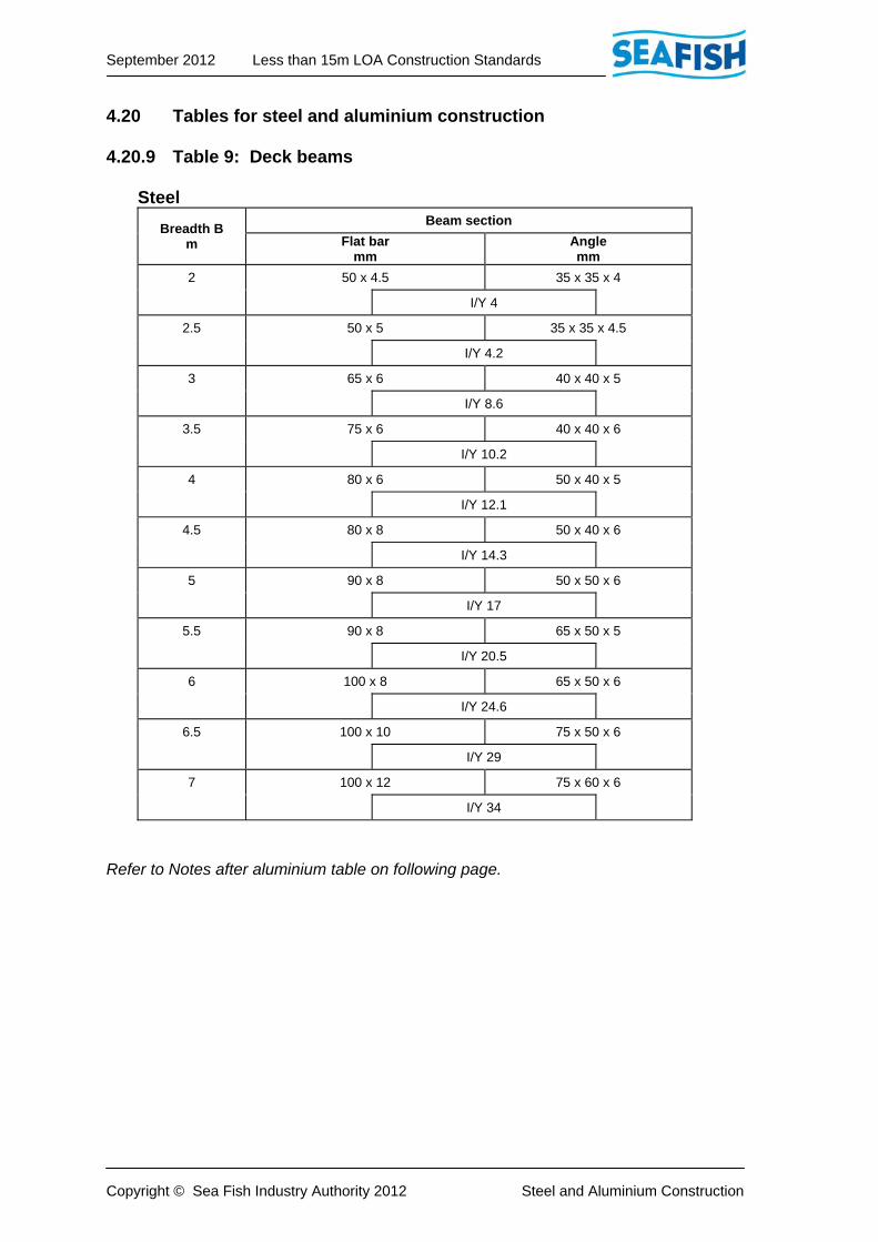
4.20 Tables for steel and aluminium construction 4.20.9 Table 9: Deck beams Steel
Breadth B m
Beam section
Flat barmm
Anglemm
2 50 x 4.5 35 x 35 x 4
I/Y 4
2.5 50 x 5 35 x 35 x 4.5
I/Y 4.2
3 65 x 6 40 x 40 x 5
I/Y 8.6
3.5 75 x 6 40 x 40 x 6
I/Y 10.2
4 80 x 6 50 x 40 x 5
I/Y 12.1
4.5 80 x 8 50 x 40 x 6
I/Y 14.3
5 90 x 8 50 x 50 x 6
I/Y 17
5.5 90 x 8 65 x 50 x 5
I/Y 20.5
6 100 x 8 65 x 50 x 6
I/Y 24.6
6.5 100 x 10 75 x 50 x 6
I/Y 29
7 100 x 12 75 x 60 x 6
I/Y 34
Refer to Notes after aluminium table on following page.

September 2012 Less than 15m LOA Construction Standards
Copyright © Sea Fish Industry Authority 2012 Steel and Aluminium Construction
4.20 Tables for steel and aluminium construction 4.20.9 Table 9: Deck beams (continued) Aluminium
Breadth B m
Beam section
Flat barmm
Angle mm
2 63.5 x 6.4 -
I/Y 6.8
2.5 63.5 x 6.4 -
I/Y 7.2
3 76.2 x 9.5 -
I/Y 14.7
3.5 76.2 x 9.5 63.5 x 38.1 x 6.4
I/Y 17.4
4 101.6 x 9.5 63.5 x 38.1 x 6.4
I/Y 20.6
4.5 101.6 x 9.5 76.2 x 50.8 x 6.4
I/Y 24.4
5 101.6 x 9.5 76.2 x 50.8 x 6.4
I/Y 28.9
5.5 101.6 x 12.7 76.2 x 76.2 x 6.4
I/Y 34.9
6 101.6 x 12.7 76.2 x 76.2 x 6.4
I/Y 41.9
6.5 - 101.6 x 76.2 x 6.4
I/Y 49.3
7 - 101.6 x 76.2 x 6.4
I/Y 57.8
Refer to Notes on following page.

September 2012 Less than 15m LOA Construction Standards
Copyright © Sea Fish Industry Authority 2012 Steel and Aluminium Construction
4.20 Tables for steel and aluminium construction 4.20.9 Table 9: Deck beams (continued) Notes:- 1. Deck beams are to be fitted at every frame and should be connected to the
frames by brackets in accordance with Figure 4.21.3.
2. Deck beams should be fitted in association with longitudinal girders and, where necessary, pillars (see Tables 4.20.10 and 4.20.11).
3. The dimensions of the sections given in the Table may be modified provided the section modulus is not reduced.
4. The Table section moduli are based on a beam spacing of 500mm. Where the spacing is varied the moduli should also be increased in direct proportion.
5. Beams supporting heavy deck loads are to be increased in depth by twice the depth of the ordinary beam.
6. Where alternative flat bar or fabricated frames are proposed in place of rolled section, details are to be submitted for approval prior to utilisation in construction.

September 2012 Less than 15m LOA Construction Standards
Copyright © Sea Fish Industry Authority 2012 Steel and Aluminium Construction
4.20 Tables for steel and aluminium construction 4.20.10 Table 10: Deck girders Steel
Breadth B m
Girder Span m
2 2.25 2.5 2.75 3
2 75 x 50 x 6 100 x 50 x 6 100 x 65 x 6 100 x 75 x 6 100 x 75 x 8
I/Y 28 I/Y 36 I/Y 45 I/Y 54 I/Y 64
3 90 x 90 x 6 100 x 65 x 7 100 x 65 x 8 100 x 75 x 8 100 x 65 x 10
I/Y 56 I/Y 58 I/Y 64 I/Y 64 I/Y 76
4 100 x 65 x 8 100 x 75 x 8 100 x 75 x 10 100 x 75 x 10 125 x 75 x 8
I/Y 64 I/Y 72 I/Y 82 I/Y 86 I/Y 94
5 100 x 75 x 8 100 x 75 x 8 137 x 102 x 6 137 x 102 x 6 137 x 102 x 7
I/Y 71 I/Y 78 I/Y 87 I/Y 102 I/Y 107
6 100 x 75 x 8 100 x 75 x 10 130 x 65 x 8 125 x 75 x 10 150 x 75 x 8
I/Y 82 I/Y 87 I/Y 95 I/Y 115 I/Y 123
7 100 x 75 x 10 130 x 65 x 8 137 x 102 x 6 150 x 75 x 8 137 x 102 x 8
I/Y 82 I/Y 94 I/Y 107 I/Y 121 I/Y 138
Refer to Notes after aluminium table on following page.

September 2012 Less than 15m LOA Construction Standards
Copyright © Sea Fish Industry Authority 2012 Steel and Aluminium Construction
4.20 Tables for steel and aluminium construction 4.20.10 Table 10: Deck girders (continued) Aluminium
Breadth B m
Girder Span m
2 2.25 2.5 2.75 3
2 101.6 x 76.2 x 6.4
101.6 x 76.2 x 7.9
152.4 x 76.2 x 9.5
152.4 x 76.2 x 9.5
152.4 x 76.2 x 9.5
I/Y 47.6 I/Y 61.2 I/Y 76.5 I/Y 91.8 I/Y 108.8
3 152.4 x 76.2 x 9.5
152.4 x 76.2 x 9.5
152.4 x 76.2 x 9.5
152.4 x 76.2 x 9.5
152.4 x 76.2 x 9.5
I/Y 95.2 I/Y 98.6 I/Y 108.8 I/Y 108.8 I/Y 129.2
4 152.4 x 76.2 x 9.5
152.4 x 76.2 x 9.5
152.4 x 76.2 x 9.5
152.4 x 76.2 x 9.5
200 x 100 x 9.5
I/Y 108.8 I/Y 122.4 I/Y 139.4 I/Y 146.2 I/Y 159.8
5 152.4 x 76.2 x 9.5
152.4 x 76.2 x 9.5
152.4 x 76.2 x 9.5
200 x 100 x 9.5
200 x 100 x 9.5
I/Y 120.7 I/Y 132.6 I/Y 147.9 I/Y 173.4 I/Y 181.9
6 152.4 x 76.2 x 9.5
152.4 x 76.2 x 9.5
200 x 100 x 9.5
200 x 100 x 9.5
200 x 100 x 9.5
I/Y 139.4 I/Y 147.9 I/Y 161.5 I/Y 195.5 I/Y 209.1
7 152.4 x 76.2 x 9.5
200 x 100 x 9.5
200 x 100 x 9.5
200 x 100 x 9.5
200 x 100 x 9.5
I/Y 139.4 I/Y 159.8 I/Y 181.9 I/Y 205.7 I/Y 234.6
Refer to Notes on following page.

September 2012 Less than 15m LOA Construction Standards
Copyright © Sea Fish Industry Authority 2012 Steel and Aluminium Construction
4.20 Tables for steel and aluminium construction 4.20.10 Table 10: Deck girders (continued) Notes:- 1. Girders should generally be fitted on the centreline, but consideration will be
given to the fitting of a girder each side of the centreline, which may be of reduced section.
2. The unsupported span of girders is not to exceed 3m.
3. The Table moduli are based on a beam spacing of 500mm. Where the beam spacing is varied, the section modulus of the girder is to be varied in direct proportion.
4. The sections in the Table may be varied or replaced by a fabricated girder, provided that the section modulus is not reduced and provided that the thickness of the girder is not less than that of the deck beams.
5. Where the girder web is notched over the deck beams, the depth of the girder web should be not less than 20mm greater than that of the beams. Girders fitted in association with flat bar beams are to be welded to the beams.
6. Girders are to be fitted with brackets at the transom and bulkheads. The depth and length of the brackets are to be as shown in Figure 4.21.4.
7. For intermediate breadths not given in the Table, the nearest breadth will apply.
September 2012 Less than 15m LOA Construction Standards
Copyright © Sea Fish Industry Authority 2012 Steel and Aluminium Construction
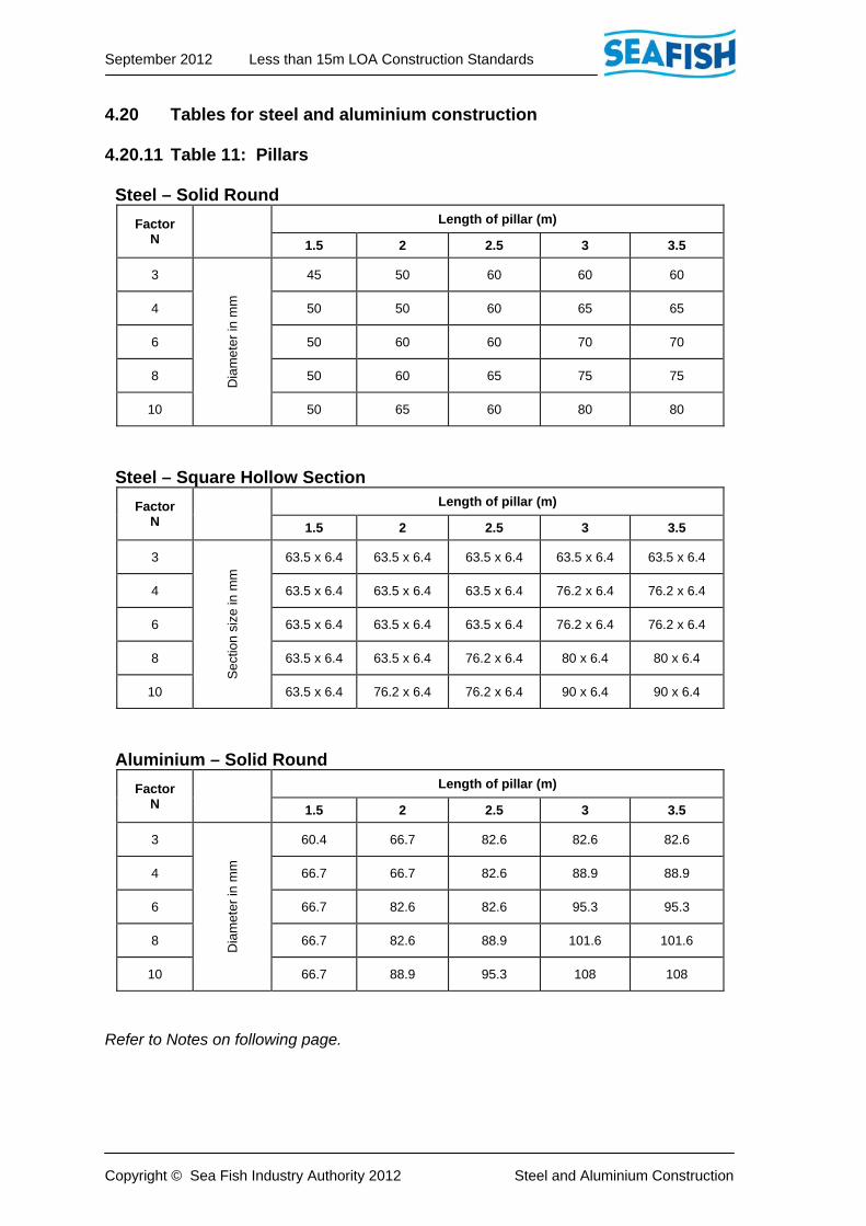
4.20 Tables for steel and aluminium construction 4.20.11 Table 11: Pillars Steel – Solid Round
Factor N
Length of pillar (m)
1.5 2 2.5 3 3.5
3
D
iam
eter
in m
m
45 50 60 60 60
4 50 50 60 65 65
6 50 60 60 70 70
8 50 60 65 75 75
10 50 65 60 80 80
Steel – Square Hollow Section
Factor N
Length of pillar (m)
1.5 2 2.5 3 3.5
3
S
ectio
n si
ze in
mm
63.5 x 6.4 63.5 x 6.4 63.5 x 6.4 63.5 x 6.4 63.5 x 6.4
4 63.5 x 6.4 63.5 x 6.4 63.5 x 6.4 76.2 x 6.4 76.2 x 6.4
6 63.5 x 6.4 63.5 x 6.4 63.5 x 6.4 76.2 x 6.4 76.2 x 6.4
8 63.5 x 6.4 63.5 x 6.4 76.2 x 6.4 80 x 6.4 80 x 6.4
10 63.5 x 6.4 76.2 x 6.4 76.2 x 6.4 90 x 6.4 90 x 6.4
Aluminium – Solid Round
Factor N
Length of pillar (m)
1.5 2 2.5 3 3.5
3
D
iam
eter
in m
m
60.4 66.7 82.6 82.6 82.6
4 66.7 66.7 82.6 88.9 88.9
6 66.7 82.6 82.6 95.3 95.3
8 66.7 82.6 88.9 101.6 101.6
10 66.7 88.9 95.3 108 108
Refer to Notes on following page.

September 2012 Less than 15m LOA Construction Standards
Copyright © Sea Fish Industry Authority 2012 Steel and Aluminium Construction
4.20 Tables for steel and aluminium construction 4.20.11 Table 11: Pillars (continued) Aluminium – Round Tube
Factor N
Length of pillar (m)
1.5 2 2.5 3 3.5
3
o/
d an
d w
all t
hick
ness
in
mm
76.2 x 6.4 88.9 x 6.4 114.3 x 6.4 114.3 x 6.4 114.3 x 6.4
4 88.9 x 6.4 88.9 x 6.4 114.3 x 6.4 127 x 6.4 127 x 6.4
6 88.9 x 6.4 114.3 x 6.4 114.3 x 6.4 152.4 x 6.4 152.4 x 6.4
8 88.9 x 6.4 114.3 x 6.4 127 x 6.4 165.1 x 6.4 165.1 x 6.4
10 88.9 x 6.4 127 x 6.4 152.4 x 6.4 - -
Notes:-
1. Factor ‘N’ for pillar supporting main deck = 1.4 ɩb
where ɩ = mean length of deck supported by pillar b = mean breadth of deck supported by pillar
2. Factor ‘N’ for pillar supporting superstructure deck = 1.07 ɩb
3. Where pillars of built-up or tubular section or aluminium alloy are used, they are to be of equivalent strength to those shown in the Table.

September 2012 Less than 15m LOA Construction Standards
Copyright © Sea Fish Industry Authority 2012 Steel and Aluminium Construction
4.20 Tables for steel and aluminium construction 4.20.12 Table 12: Watertight bulkheads Steel
Depth of bulkhead
at centreline m
Thickness of
plating mm
Sectionmodulus
of stiffeners (I/Y cm3)
Stiffener sections meeting modulus required
Anglemm
Flat Bar mm
0.75 3.5 4 - 50 x 4.5
1 4 4.4 - 50 x 5
1.25 4.5 6.2 - 60 x 5
1.5 5 7.5 - 60 x 6
1.75 5 9.1 40 x 40 x 5 70 x 6
2 6 12 45 x 45 x 5 70 x 8
2.25 6 15 50 x 40 x 6 75 x 8
2.5 6 17.7 50 x 50 x 6 75 x 10
2.75 6 21.3 65 x 50 x 5 80 x 10
3 6.5 26 60 x 60 x 6 90 x 10
3.25 6.5 30.6 75 x 50 x 6 100 x 10
3.5 6.5 35 70 x 70 x 6 100 x 12
3.75 6.5 41 75 x 75 x 6 110 x 12
4.0 8 48 80 x 60 x 8 110 x 12
Refer to Notes after aluminium table on following page.

September 2012 Less than 15m LOA Construction Standards
Copyright © Sea Fish Industry Authority 2012 Steel and Aluminium Construction
4.20 Tables for steel and aluminium construction 4.20.12 Table 12: Watertight bulkheads (continued) Aluminium
Depth of bulkhead
at centreline m
Thickness of
plating mm
Sectionmodulus
of stiffeners (I/Y cm3)
Stiffener sections meeting modulus required
Anglemm
Flat Bar mm
0.75 5 6.8 - 63.5 x 6.4
1 5 7.5 - 63.5 x 6.4
1.25 6 10.6 - 76.2 x 6.4
1.5 6.4 12.8 44.5 x 44.5 x 6.4 76.2 x 6.4
1.75 6.4 15.5 50.8 x 50.8 x 6.4 76.2 x 9.5
2 8 20.4 63.5 x 38.1 x 6.4 76.2 x 12.7
2.25 8 25.5 76.2 x 50.8 x 6.4 76.2 x 12.7
2.5 8 30.1 76.2 x 50.8 x 6.4 101.6 x 9.5
2.75 8 36.3 76.2 x 76.2 x 6.4 101.6 x 12.7
3 8 44.2 76.2 x 76.2 x 6.4 127 x 12.7
3.25 8 52.1 101.6 x 76.2 x 6.4 127 x 12.7
3.5 8 59.5 101.6 x 76.2 x 6.4 127 x 12.7
3.75 8 69.7 101.6 x 101.6 x 6.4 152.4 x 12.7
4.0 10 81.6 101.6 x 101.6 x 6.4 152.4 x 12.7
Notes:- 1. Watertight bulkheads are to extend from the keel to the lowest continuous
deck/flat above the deepest operational waterline.
2. The moduli of stiffeners in the Table are based on a stiffener spacing of 500mm. Where the spacing is varied the modulus should be varied in direct proportion.
3. The stiffener sections given in the Table may be varied provided the section moduli are not reduced.
4. Where the depth of the bulkhead at any stiffener is less than 2.5m, brackets or other end connections may be omitted, unless connected to deck girders or longitudinals.
5. Where longitudinal bulkheads, decks, tank tops, etc. butt to bulkhead plating, these connections may be taken into consideration when determining stiffener and plating scantlings.
6. For details of bracket connections see Figures 4.21.3 and 4.21.4.
September 2012 Less than 15m LOA Construction Standards
Copyright © Sea Fish Industry Authority 2012 Steel and Aluminium Construction
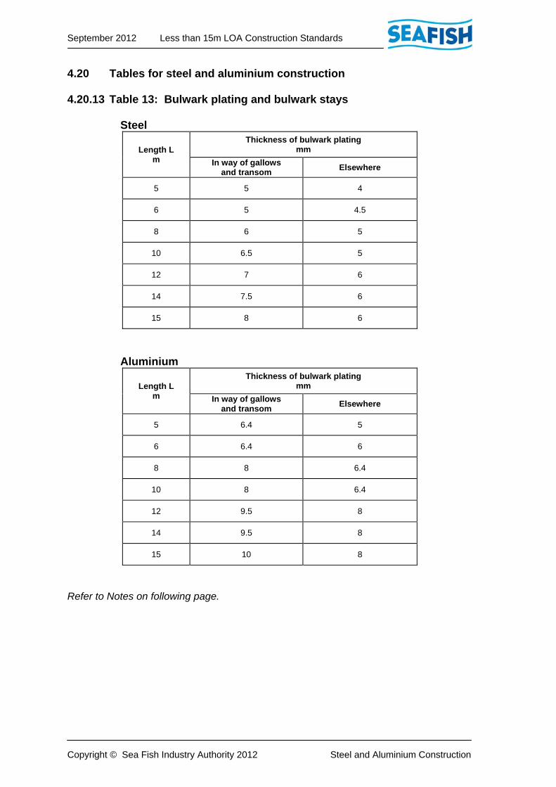
4.20 Tables for steel and aluminium construction 4.20.13 Table 13: Bulwark plating and bulwark stays Steel
Length L m
Thickness of bulwark plating mm
In way of gallowsand transom
Elsewhere
5 5 4
6 5 4.5
8 6 5
10 6.5 5
12 7 6
14 7.5 6
15 8 6
Aluminium
Length L m
Thickness of bulwark plating mm
In way of gallowsand transom
Elsewhere
5 6.4 5
6 6.4 6
8 8 6.4
10 8 6.4
12 9.5 8
14 9.5 8
15 10 8
Refer to Notes on following page.

September 2012 Less than 15m LOA Construction Standards
Copyright © Sea Fish Industry Authority 2012 Steel and Aluminium Construction
4.20 Tables for steel and aluminium construction 4.20.13 Table 13: Bulwark plating and bulwark stays (continued) Notes:- 1. Where stays consist of a flanged flat plate, the flange width is to be not less
than 50mm, and the plate thickness not less than that of the bulwark plating locally.
2. Only that section of the bulwark stay which is welded to the deck is to be used when determining the modulus of the stay.
3. Where length ‘L’ is between those shown in the Table, the thickness is to be that shown for the nearest length.
4. Where the shell plating is extended to bulwark height, the bulwark thickness may be that required for the shell plating except in way of gallows, and subject to the approval of the Surveyor.

September 2012 Less than 15m LOA Construction Standards
Copyright © Sea Fish Industry Authority 2012 Steel and Aluminium Construction
4.20 Tables for steel and aluminium construction 4.20.14 Table 14: Chine bars Steel
Length L m
Diameter mm
5 15
6 15
8 18
10 22
12 25
14 32
15 35
Aluminium
Length L m
Diameter mm
5 19
6 19
8 22.3
10 28.6
12 31.8
14 41.3
15 44.5
Note:- 1. When the length ‘L’ falls between those given in the Table, the diameter of the
bars should be to the nearest length.
2. Diameters shown are for solid round section. Proposals for the use of alternative sections are to be submitted for consideration and approval.

September 2012 Less than 15m LOA Construction Standards
Copyright © Sea Fish Industry Authority 2012 Steel and Aluminium Construction
4.20 Tables for steel and aluminium construction 4.20.15 Table 15: Shelter deck beams Steel
Breadth B m
(Modulus cm3) - Recommended scantling Frame
spacing mm
Full shelter Partial shelter
Weathertight (WT) Non-weathertight
3 (5.2) 65 x 5 FB (4.8) 50 x 5 FB (3.2) 50 x 5 FB 500
3.5 (6.4) 65 x 5 FB (5.2) 65 x 5 FB (3.8) 50 x 5 FB 500
4 (7.4) 65 x 6 FB (5.9) 65 x 5 FB (4.4) 50 x 5 FB 500
4.5 (8.3) 65 x 6 FB (6.6) 65 x 5 FB (4.9) 50 x 6 FB 500
5 (9.2) 75 x 6 FB (7.4) 65 x 6 FB (5.5) 65 x 5 FB 500
5.5 (10.1) 75 x 6 FB (8.2) 65 x 6 FB (6) 65 x 5 FB 500
6 (13.2) 75 x 10 FB (10.5) 75 x 6 FB (7.9) 65 x 6 FB 500
6.5 (17.5) 75 x 10 FB (14) 75 x 10 FB (10.5) 75 x 6 FB 500
7 (21.8) 65 x 50 x 6 OA (17.5) 75 x 10 FB (13) 75 x 10 FB 500
Aluminium
Breadth B
m
(Modulus cm3) - Recommended scantling Frame
spacing mm
Full shelter Partial shelter
Weathertight (WT) Non-weathertight
3.5 (10.9) 75 x 6.4 FB (8.7) 63 x 6.4 FB (6.6) 63 x 6.4 FB 500
4 (12.5) 75 X 6.4 FB (10) 75 x 6.4 FB (7.5) 63 x 6.4 FB 500
4.5 (14) 75 x 9.5 FB (11.2) 75 x 6.4 FB (8.4) 63 x 6.4 FB 500
5 (15.6) 76.2 x 9.5 FB (12.5) 76.2 x 6.4 FB (9.4) 63 x 6.4 FB 500
5.5 (20.6) 63.5 x 38 x 6 OA (13.8) 76.2 x 9.5 FB (10.3) 76.2 x 6.4 FB 500
6 (22.4) 63.5 x 50 x 6 OA (20.6) 63.5 x 38 x 6 OA (13.4) 76.2 x 6.4 FB 500
6.5 (29.6) 76.2 x 50.8 x 6.4 (23.7) 63.5 x 50.8 x 6.4 (20.6) 63.5 x 38.1 x 6.4 500
7 (37) 76.2 x 76.2 x 6.4 (29.6) 63.5 x 50.8 x 6.4 (22.2) 63.5 x 50.8 x 6.4 500
Refer to Notes on following page.
September 2012 Less than 15m LOA Construction Standards
Copyright © Sea Fish Industry Authority 2012 Steel and Aluminium Construction
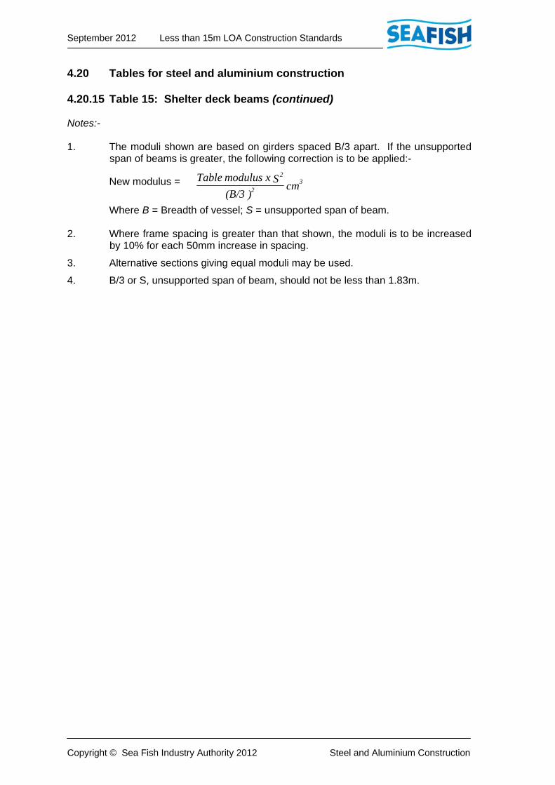
4.20 Tables for steel and aluminium construction 4.20.15 Table 15: Shelter deck beams (continued) Notes:- 1. The moduli shown are based on girders spaced B/3 apart. If the unsupported
span of beams is greater, the following correction is to be applied:-
New modulus =
Where B = Breadth of vessel; S = unsupported span of beam. 2. Where frame spacing is greater than that shown, the moduli is to be increased
by 10% for each 50mm increase in spacing.
3. Alternative sections giving equal moduli may be used.
4. B/3 or S, unsupported span of beam, should not be less than 1.83m.
cm )(B/3
S x modulus Table 32
2

September 2012 Less than 15m LOA Construction Standards
Copyright © Sea Fish Industry Authority 2012 Steel and Aluminium Construction
4.20 Tables for steel and aluminium construction 4.20.16 Table 16: Shelter deck side plating and stiffeners Side stiffeners
Depth D
Steel Aluminium
Modulus Section Modulus Section
1.5 (6.3) 65 x 5 FB (10.7) 75 x 6.4 FB
2 (8.4) 65 x 6 FB (14.2) 65 x 38 x 6.4 OA
76.2 x 9.5 FB
2.5 (10.5) 75 x 6 FB (17.8) 65 x 38 x 6.4 OA
76.2 x 9.5 FB
3 (12.6) 75 x 10 FB (21.4) 65 x 65 x 6.4 OA
76.2 x 12.7 FB
3.5 (14.7) 65 x 38 x 6 OA
75 x 10 FB (25)
65 x 65 x 6.4 OA
101.6 x 9.5 FB
4 (16.8) 65 x 38 x 6 OA
75 x 10 FB (28.5)
65 x 65 x 6.4 OA
101.6 x 9.5 FB
Shelter side plating
Length L
Weathertight Non-weathertight Partial
Steel Aluminium Steel Aluminium Steel Aluminium
10m and below 4 5 4 5 4 5
Over 10m 4.5 5.5 4.5 5.5 4.5 5
Notes:- 1. Sizes are based on frame spacing of 500mm. Where the spacing is greater,
the plating thickness is to be increased at the rate of 0.5mm per 50mm spacing difference.
2. Alternative sections giving equal moduli may be fitted. The next greater standard aluminium alloy section is to be utilised when stated sections are not available.

September 2012 Less than 15m LOA Construction Standards
Copyright © Sea Fish Industry Authority 2012 Steel and Aluminium Construction
4.20 Tables for steel and aluminium construction 4.20.17 Table 17: Shelter deck plating
Length L
Weathertight Non-weathertight Partial
Steel Aluminium Steel Aluminium Steel Aluminium
10m and below 4.5 5 4.5 5 4 5
Over 10m 5 6 5 6 5 5.5
Note:- 1. Sizes are based on frame spacing of 500mm. Where the spacing is greater,
the plating thickness is to be increased at the rate of 0.5mm per 50mm spacing difference.

September 2012 Less than 15m LOA Construction Standards
Copyright © Sea Fish Industry Authority 2012 Steel and Aluminium Construction
4.20 Tables for steel and aluminium construction 4.20.18 Table 18: Shelter deck girders Steel
Weathertight
Girder spacing
m
Distance between supports (m)
2 2.5 3
Modulus (cm3) - recommended section (angle)
1.5 (43) 100 x 50 x 6 (67) 100 x 100 x 6 (96) 150 x 75 x 10
2 (57) 100 x 75 x 6 (89) 100 x 100 x 6 (129) 150 x 75 x 10
Non-weathertight
1.5 (25.8) 65 x 50 x 6 (40.2) 100 x 50 x 6 (57.6) 100 x 75 x 6
2 (34.2) 100 x 50 x 6 (53.4) 100 x 75 x 6 (77.4) 100 x 100 x 6
Partial
1.5 (19.3) 65 x 50 x 6 (30.1) 75 x 50 x 6 (43.3) 100 x 50 x 6
2 (25.7) 65 x 50 x 6 (40.1) 100 x 50 x 6 (57.8) 100 x 75 x 6
Aluminium
Weathertight
1.5 (73) 100 x 100 x 6.5 (114) 150 x 75 x 9.5 (163) 200 x 75 x 9.5
2 (97) 150 x 75 x 9.5 (151) 150 x 75 x 9.5 (219) 200 x 100 x 9.5
Non-weathertight
1.5 (43.9) 100 x 50 x 6.4 (68.4) 100 x 100 x 6.4 (98) 150 x 75 x 9.5
2 (58.2) 100 x 75 x 6.4 (90.5) 150 x 75 x 9.4 (131.6) 150 x 75 x 9.5
Partial
1.5 (25.7) 65 x 50 x 6.4 (40.1) 100 x 50 x 6.4 (57.7) 100 x 75 x 6.4
2 (34.2) 75 x 50 x 6.4 (53.5) 100 x 75 x 6.4 (77) 100 x 100 x 6.4
Notes:- 1. Maximum spacing of girders is not to exceed B/3.
2. The fitting of a single centreline girder may be considered in vessels where B is less than 4m.
3. The unsupported span of girders is not to exceed 3m.
4. Pillars supporting girders are to comply with Table 4.20.11.
5. Where the girder web is cut over deck beams, the depth of the web is not to be less than 25mm greater than the beam web.
6. Ends of girders are to be bracketed to the satisfaction of the Surveyor.
7. Scantlings for aluminium alloy angles shown may be substituted by the next greater standard section.

September 2012 Less than 15m LOA Construction Standards
Copyright © Sea Fish Industry Authority 2012 Steel and Aluminium Construction
4.21 Figures & Illustrations 4.21.1 Scantling numeral dimensions – steel and aluminium vessels
L x B x D = Scantling numeral
Length overall measured in a straight line from the fore side of stem at top to after side of stern / transom or fore side of the bulbous bow to after side of stern / transom if that be greater. Scantling length L measured in a straight line parallel to an assumed waterline at 0.85 x moulded depth, above top of keel amidships. Breadth B measured to outside of plating at the greatest breadth of the vessel, but excluding fenders or rub rails. Depth D measured amidships from top of plate keel or the line of intersection of the inside of the shell plating at keel to top of deck beam at side. (see fig. 1a).

September 2012 Less than 15m LOA Construction Standards
Copyright © Sea Fish Industry Authority 2012 Steel and Aluminium Construction
4.21 Figures and illustrations 4.21.2 Scantling numeral dimensions – steel and aluminium vessels
September 2012 Less than 15m LOA Construction Standards
Copyright © Sea Fish Industry Authority 2012 Steel and Aluminium Construction
4.21 Figures and illustrations 4.21.3 Beam knees and longitudinal brackets

September 2012 Less than 15m LOA Construction Standards
Copyright © Sea Fish Industry Authority 2012 Steel and Aluminium Construction
4.21 Figures and illustrations 4.21.4 Longitudinal girder brackets

September 2012 Less than 15m LOA Construction Standards
Copyright © Sea Fish Industry Authority 2012 Steel and Aluminium Construction
4.21 Figures and illustrations 4.21.5 Side frame bottom brackets
September 2012 Less than 15m LOA Construction Standards
Copyright © Sea Fish Industry Authority 2012 Steel and Aluminium Construction
4.21 Figures and illustrations 4.21.6 Bottom construction
For integral tanks see section 4.5

September 2012 Less than 15m LOA Construction Standards
Copyright © Sea Fish Industry Authority 2012 Steel and Aluminium Construction
4.21 Figures and illustrations 4.21.7 Bilge keel details
See section 4.17

September 2012 Less than 15m LOA Construction Standards
Copyright © Sea Fish Industry Authority 2012 Steel and Aluminium Construction
4.21 Figures and illustrations 4.21.8 Longitudinal shell plate stringer position
September 2012 Less than 15m LOA Construction Standards
Copyright © Sea Fish Industry Authority 2012 Steel and Aluminium Construction
4.21 Figures and illustrations 4.21.9 Typical keel arrangement
See section 4.6 & Table 4.20.1

September 2012 Less than 15m LOA Construction Standards
Copyright © Sea Fish Industry Authority 2012 Steel and Aluminium Construction
4.21 Figures and illustrations 4.21.10 Deck girder arrangements
See sections 4.12, 4.13 & Tables 4.20.9, 4.20.10
September 2012 Less than 15m LOA Construction Standards
Copyright © Sea Fish Industry Authority 2012 Steel and Aluminium Construction
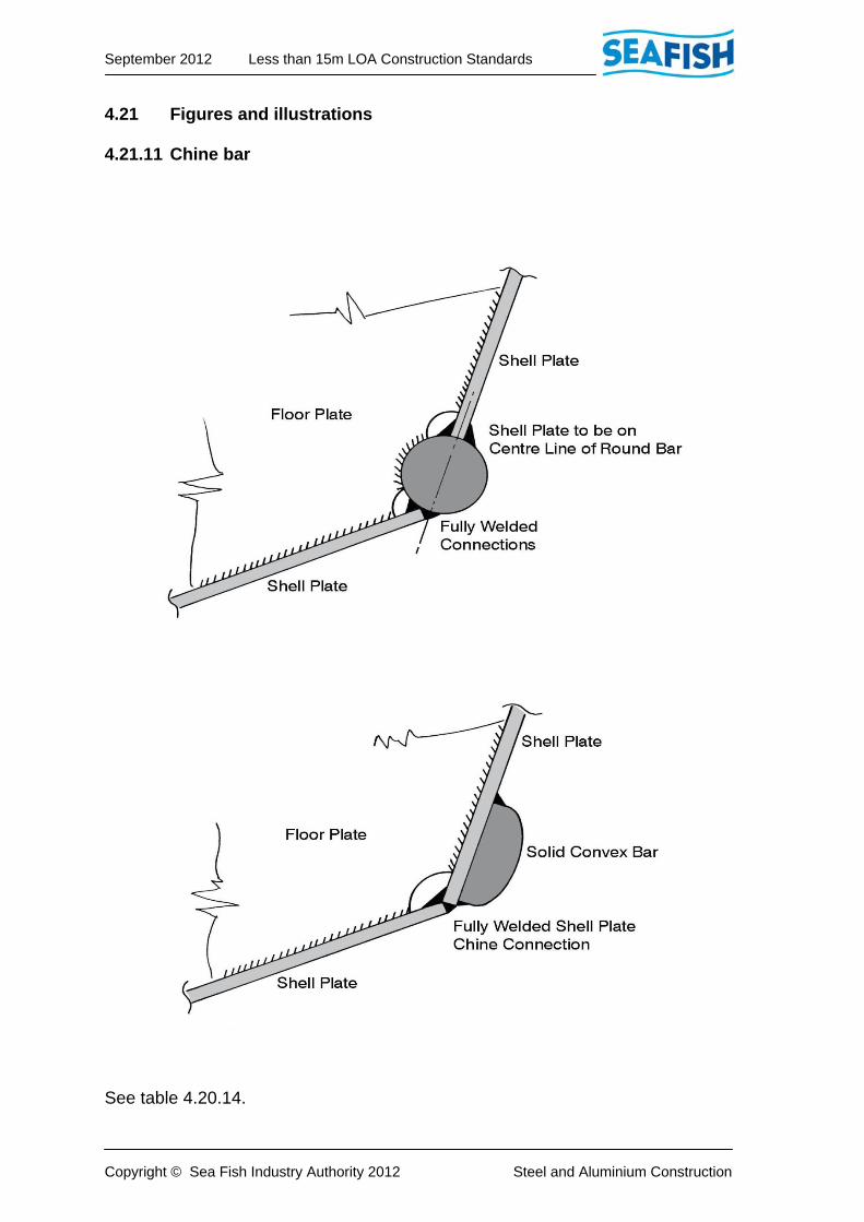
4.21 Figures and illustrations 4.21.11 Chine bar
See table 4.20.14.