part b submittion
DESCRIPTION
Studio AirTRANSCRIPT

1
ARCHITECTURE DESIGN STUDIO: AIR
William Zeng 363773
2
CONTENTS
XX. INTRODUCTIONA1. ARCHITECTURE AS DISCOUSEA2. COMPUTATIONAL ARCHITECTUREA3. PARAMETRIC MODELINGA4. ALGORITHMIC EXPLORATIONSA5. CONCLUSIONA6. LEARNING OUTCOME
Contents
PART A: EOI I: CASE FOR INNOVATION
PART B: EOI II: DESIGN APPROACH
B1. DESIGN FOCUSB2. CASE STUDY 1.0B3. CASE STUDY 2.0B4. TECHNIQUE: DEVELOPMENTB5. TECHNIQUE: PROTOTYPESB6. TECHNIQUE PROPOSALB7. ALGORITHMIC SKETCHEESB8. LEARNING OBJECTIVES AND OUTCOMES
PART B: EOI II: DESIGN APPROACH
C1. GATEWAY PROJECT: DESIGN CONCEPTC2. GATEWAY PROJECT: TECTONIC ELEMENTSC3. GATEWAY PROJECT: FINAL MODELC4. ALGORITHMIC SKETCHESC5. LEARNING OBJECTIVE AND OUTCOMES

3
About myself
Hello everyone, my name is Bixiang Zeng, William is the prefer name I used. I’m from China and this is my third year of Archi-tecture in Melbourne University. I have just finished a two months intership with MarchesePartners back in Guangzhou. I’ve done some of the CAD drawings and sketchup models for some projects in Sydney. One of the most interesting subjects about digital design was Virtual Environment as I’ve learnt a bit of digital design during the course.
Introduction to Myself

4
Project in Virtual Environment
These were some of the photos of my project in Virtual Environment. These works has en-gaged to digital design to some degree and obviously, digital design now is the indispensable way to architecture design.
Digital tools always give people a bigger range to create as it could model thing much quicker and precise. People could create some very interesting surface on the building such as the commerce building for RMIT. A new approach can be found in digital modeling.
Virtual Environment
5
ARCHITECTURE AS A DISCOURSE
A.1 Architecture As Discourese
1.Cited from: Architecture and Visual Culture: Definitions, Concepts,
Contexts. (Edinburgh: Edinburgh University Press, 2005), P.103
2. Dictionary.com
3. Cited from: The Autopoiesis of Architecture: A New Framework for
Architecture (Chichester: Wiley),P. 18
social or political impact on this building as Schumacher has
said that:
“Architecture discourse is reflected architecture’s social and political impact and responsibility.” -----Schumacher, Patrik3
In this course, during the gateway project, how to engage the
project with the brief that can express the attitude towards the
social and political reponse without harming the shape of art
has become one of the most important things.
In this part, two public buildings will be used to demonstrate
how architecture reflects its social or political impacts through
several aspects, namely framing views, engagement with public
and representation.
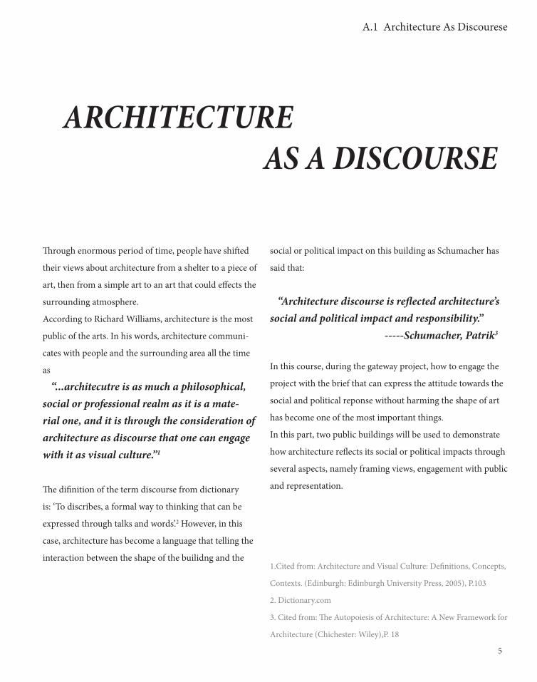
Through enormous period of time, people have shifted
their views about architecture from a shelter to a piece of
art, then from a simple art to an art that could effects the
surrounding atmosphere.
According to Richard Williams, architecture is the most
public of the arts. In his words, architecture communi-
cates with people and the surrounding area all the time
as
“...architecutre is as much a philosophical, social or professional realm as it is a mate-rial one, and it is through the consideration of architecture as discourse that one can engage with it as visual culture.”1
The difinition of the term discourse from dictionary
is: ‘To discribes, a formal way to thinking that can be
expressed through talks and words’.2 However, in this
case, architecture has become a language that telling the
interaction between the shape of the builidng and the
6
A.1 Architecture As Discourese

7
A.1 Architecture As Discourese
PRECEDENTSDUTCH EMBASSY REM KOOLHAAS
1. commons.wikimedia.org
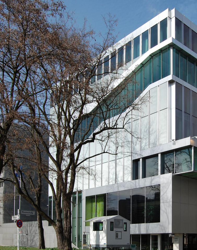
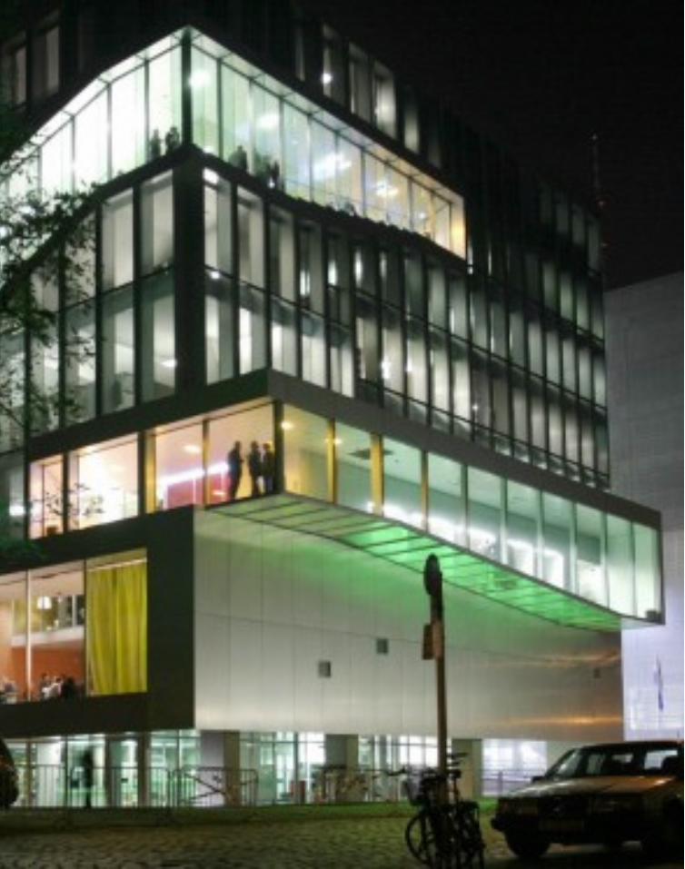
The first public building that would illus-trate the argument would be the Nether-lands Embassy in Berlin. It is designed by Rem Koolhaas and the building was opened in 2004. Some people may argue that the embassy should be a political building rather than a public building. However, it is considered as a semi-public political building.
First of all, the reason why this embassy stands out from other embassy building is it frames views. Unlike the other embassy, which the view would be the building itself, the Dutch Embassy in Berlin frames views for people to view at. By having views for people, people would accept the building as it is part of the surrounding environment easily. This would illustrate how well the building is communicating with the sur-rounding environment through the views that it frames.
Moreover, similar with some Rem’s works later in his career, engaging with the public is one of his main themes. Surprisingly, a public space for people to rest is located on the ground floor of this embassy. This act changes surrounding atmosphere. An embassy should be solemn and strictly controlled. However, its engagement with people around makes the embassy inte-grated into the surrounding office
8
A.1 Architecture As Discourese
http://www.oma.com/proj-ects/2003/netherlands-embassy
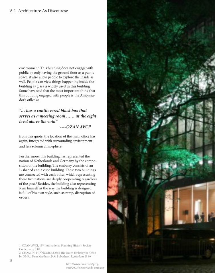
environment. This building does not engage with public by only having the ground floor as a public space, it also allow people to explore the inside as well. People can view things happening inside the building as glass is widely used in this building. Some have said that the most important thing that this building engaged with people is the Ambassa-dor’s office as
“… has a cantilevered black box that serves as a meeting room …… at the eight level above the void” ----OZAN AVCI1
from this quote, the location of the main office has again, integrated with surrounding environment and less solemn atmosphere.
Furthermore, this building has represented the nation of Netherlands and Germany by the compo-sition of the building. The embassy consists of an L-shaped and a cube building. These two buildings are connected with each other, which representing these two nations are deeply cooperating regardless of the past.2 Besides, the building also representing Rem himself as the way the building is designed is full of his own style, such as ramp, disruption of orders.
1. OZAN AVCI, 15th International Planning History Society Conference, P. 07.2. CHASLIN, FRANCOIS (2004): The Dutch Embassy in Berlin by OMA / Rem Koolhaas, NAi Publishers, Rotterdam. P. 90.
9
A.1 Architecture As Discourese

10
A.1 Architecture As Discourese
11
A.1 Architecture As Discourese
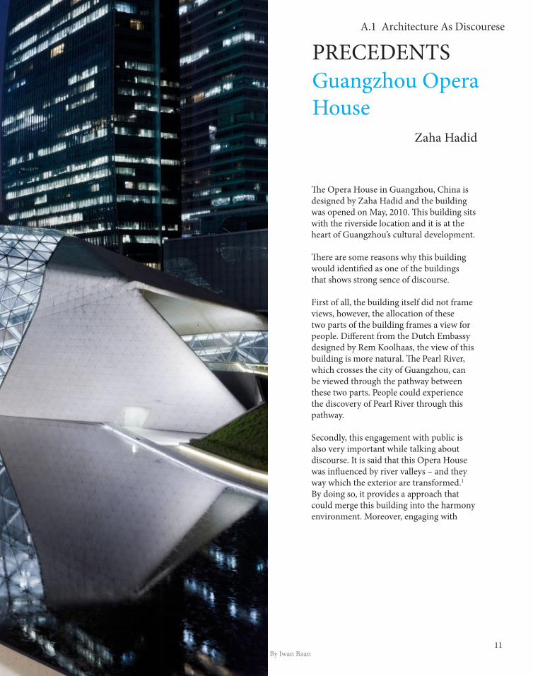
Guangzhou Opera House Zaha Hadid
The Opera House in Guangzhou, China is designed by Zaha Hadid and the building was opened on May, 2010. This building sits with the riverside location and it is at the heart of Guangzhou’s cultural development.
There are some reasons why this building would identified as one of the buildings that shows strong sence of discourse.
First of all, the building itself did not frame views, however, the allocation of these two parts of the building frames a view for people. Different from the Dutch Embassy designed by Rem Koolhaas, the view of this building is more natural. The Pearl River, which crosses the city of Guangzhou, can be viewed through the pathway between these two parts. People could experience the discovery of Pearl River through this pathway.
Secondly, this engagement with public is also very important while talking about discourse. It is said that this Opera House was influenced by river valleys – and they way which the exterior are transformed.1 By doing so, it provides a approach that could merge this building into the harmony environment. Moreover, engaging with
By Iwan Baan
PRECEDENTS
12
A.1 Architecture As Discourese
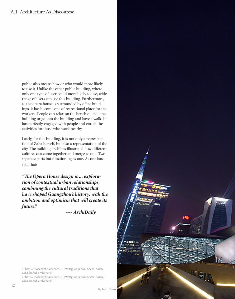
public also means how or who would more likely to use it. Unlike the other public building, where only one type of user could more likely to use, wide range of users can use this building. Furthermore, as the opera house is surrounded by office build-ings, it has become one of recreational place for the workers. People can relax on the bench outside the building or go into the building and have a walk. It has perfectly engaged with people and enrich the activities for those who work nearby.
Lastly, for this building, it is not only a representa-tion of Zaha herself, but also a representation of the city. The building itself has illustrated how different cultures can come together and merge as one. Two separate parts but functioning as one. As one has said that:
“The Opera House design is ... explora-tion of contextual urban relationships, combining the cultural traditions that have shaped Guangzhou’s history, with the ambition and optimism that will create its future.” ---- ArchiDaily
1. http://www.archdaily.com/115949/guangzhou-opera-house-zaha-hadid-architects/2. http://www.archdaily.com/115949/guangzhou-opera-house-zaha-hadid-architects/
By Iwan Baan

13
A.1 Architecture As Discourese
14
A.2 Computational Architecture
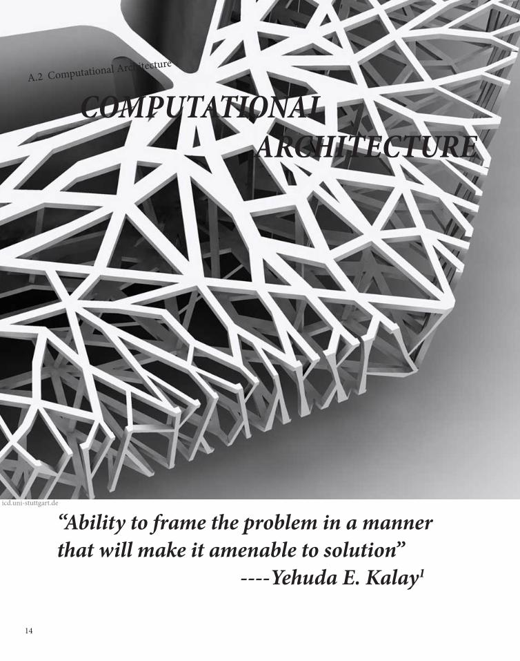
COMPUTATIONAL ARCHITECTURE
“Ability to frame the problem in a manner that will make it amenable to solution” ----Yehuda E. Kalay1
icd.uni-stuttgart.de

15
Throughout enormous period of time, the way of design-ing has changed from using hand drawing with pencil and easier to use computer to conduct digital experience.Some people believe that
“design computation is still only seen by many as ‘just a tool’ abd renite frin tge reak vysubess if creatuve desugb […]” ---Frazer, John H.2
However, using computation as a tool is not computa-tional architecture, it is just computerization.
Computational Architecture is that computation or computing as a computer-based design tool. It would be a new way to approach building design and it also be-comes one of the most important parts of digital design.
By having computation, design process has been re-shaped; the order of the process is no longer linear. The order may be disorder. Two photos were shown on the lecture slides that the order of project phases could be varies.3 By having changes on the order of project phases, more critical aspect could be covered during the design or construction period.
Computation can also brings more dynamic shapes for designer to choose. No doubt that it has increases the range of conceivable geometries and enhance designer’s creativity. By doing so, the range of achievable geom
etries has increased as well. However, as the technology level of reality world is limited by the development of the industry, the increase in achievable range is slower than the increase in conceivable. Nevertheless, computation brings a brighter future of the shape of the building.
Façade is no longer a flat wall that distinguish the exterior and interior, it has another function that is to decorate the build-ing as well. In the past, decoration is installed separately on the façade. However, computation allows people to pre-fabricate the façade through modeling on it. This has save not only the budget, but also the time commitment on the building during the construction.
1.Cited from: Frazer, John H. (2006). ‘The Generation of Virtual Proto-
types for Performance Optimization’
2. Cited from Terzidis, Kostas (2006). Algorithmic Architecture (Bos-
ton, MA: Elsevier), p. xi
3. Week Two Lecture Slides, Introduction to Computation, p. 42
16
A.2 Computational Architecture

17
A.2 Computational Architecture
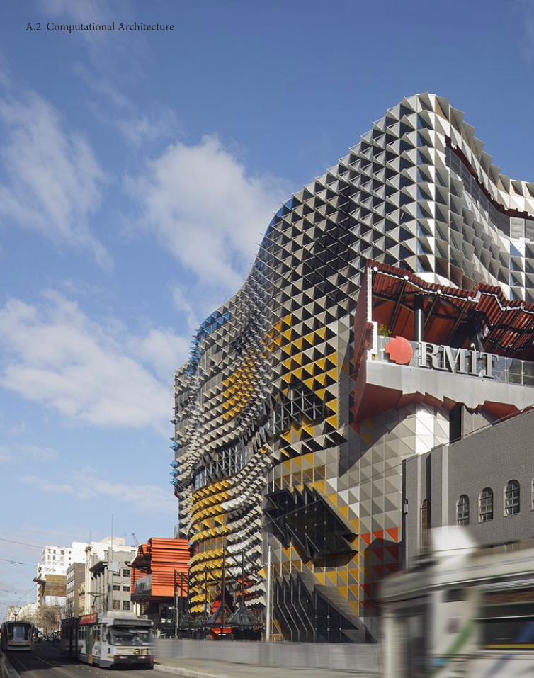
RMIT NEW ACA-DEMIC BUILDING LYONS ARCHITECTS
The RMIT new Academic Building was designed by LYON ARCHITECTS at March 2009 on Swanston Street.
One of the reasons why this RMIT new Academic Building would become my precedent is because the construction period is very short. 10 stories multi-functional teaching space had been built within two years. The reason why con-struction could be finished in such a short time is due to the use of pre-fabricate ma-terial. Computation allows the designer to estimate the
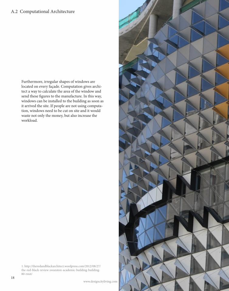
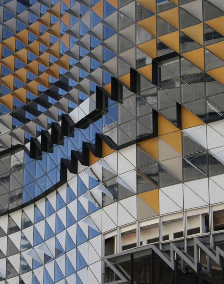
Secondly, colorful surface is one of its symbols that differ from other buildings. The striking multi-coloured geometric facade which features on all sides of the building. By using computation, it allows people to give functional activities for these geometric façade. These triangular windows and sun shades provide the bold and colourful identity which connects with the RMIT architectural branding.1
http://www.lyonsarch.com.au/rmit-university-swanston-academic-building/?b=1
PRECEDENTS
18
A.2 Computational Architecture
Furthermore, irregular shapes of windows are located on every façade. Computation gives archi-tect a way to calculate the area of the window and send these figures to the manufacture. In this way, windows can be installed to the building as soon as it arrived the site. If people are not using computa-tion, windows need to be cut on site and it would waste not only the money, but also increase the workload.
www.designcityliving.com
1. http://theredandblackarchitect.wordpress.com/2012/08/27/the-red-black-review-swanston-academic-building-building-80-rmit/
19
A.2 Computational Architecture

20
A.2 Computational Architecture
21
A.2 Computational Architecture
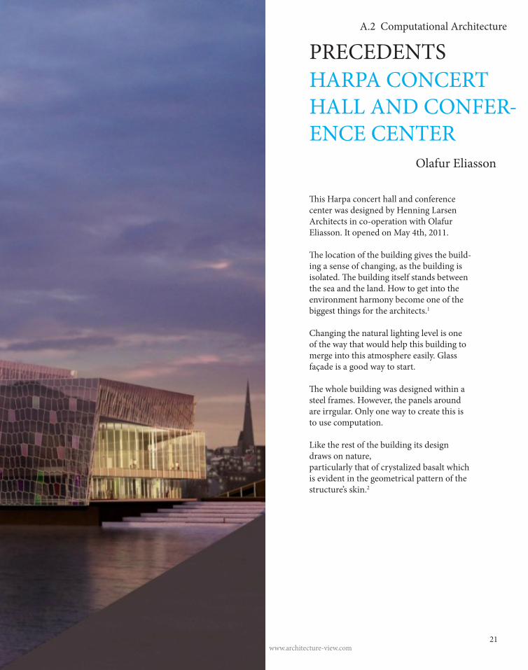
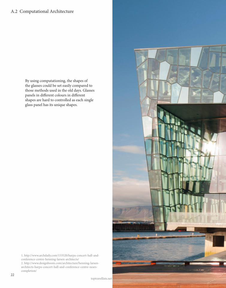
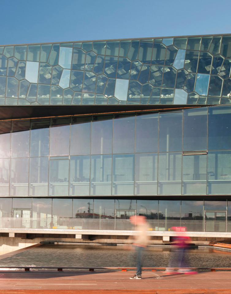
HARPA CONCERT HALL AND CONFER-ENCE CENTER Olafur Eliasson
www.architecture-view.com
PRECEDENTS
This Harpa concert hall and conference center was designed by Henning Larsen Architects in co-operation with Olafur Eliasson. It opened on May 4th, 2011.
The location of the building gives the build-ing a sense of changing, as the building is isolated. The building itself stands between the sea and the land. How to get into the environment harmony become one of the biggest things for the architects.1
Changing the natural lighting level is one of the way that would help this building to merge into this atmosphere easily. Glass façade is a good way to start.
The whole building was designed within a steel frames. However, the panels around are irrgular. Only one way to create this is to use computation.
Like the rest of the building its design draws on nature, particularly that of crystalized basalt which is evident in the geometrical pattern of the structure’s skin.2
22toptravellists.net
A.2 Computational Architecture
By using computationing, the shapes of the glasses could be set easily compared to those methods used in the old days. Glasses panels in different colours in different shapes are hard to controlled as each single glass panel has its unique shapes.
1. http://www.archdaily.com/153520/harpa-concert-hall-and-conference-centre-henning-larsen-architects/2. http://www.designboom.com/architecture/henning-larsen-architects-harpa-concert-hall-and-conference-centre-nears-completion/
23
A.2 Computational Architecture
24
A.3 Parametric Modelling
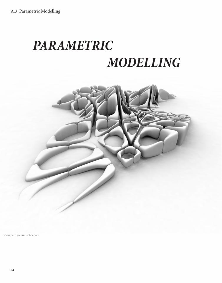
PARAMETRIC MODELLING
www.patrikschumacher.com

25
A.3 Parametric Modelling
Parametric modeling is underlying the principle of con-
nectivity of elements. By using the parametric modeling,
architects need to identify all the relationship between
different elements, different groups. The reason why
parametric modelling is unique is because of the idea of
explicit relationship between parameters and a geometry.
Designer can control the value of each groups or even
elements to create complex surfaces and curve. There are
three main approaches to parametric modelling, Graph-
based, Logic-based and Algebraic approach.
Each of these three approaches have its own advantages.
For example, Graph-based is more reliable, the speed
and the clarity of the solution. The sequence of this
approach is directed by the arrows to nodes.2 However,
once the direction was wrong, the outcome will become
disaster.
“Parametric Modelling is to marks parts of a de-sign, relate and change together in a coordinated way.” ---Woodbury, Robert1
By having parametric modeling, mathematical thinking needs
to be used. Architects or designers need to know the relation-
ship between two elements.
It is always important to think the impact of having the para-
metric modeling. Parametric modeling can be learnt by any
one, as long as they know the relationship between the elements
that are going to be used. More and more architects will use
parametric modeling as their design method. In such a digital
age, the crucial things for a good architecture should be context.
The building should be able to express the architect’s idea
through the building itself.
1. Woodbury, Robert (2010), Elements of Parametric design (London: Routledge) pp.52. Woodbury, Robert (2010), Elements of Parametric design (London: Routledge) pp.7

26
A.3 Parametric Modelling

27
A.3 Parametric Modelling
THE WATERCUBE PTW ARCHITECTS
PRECEDENTS
Aviva Stadium in Dublin is designed by Populous and engineered by Buro Happold in 1878.1
In this project, it illustrate that parametric modeling can engage in multi-disciplinary approach in entire design process and con-struction phase.
The digital model of this building has been shared with different parties and refine-ments were made. In this case, parametric modeling acts as a bridge that connects those suggestions.
During the lecture, it is said that paramet-ric modeling provides control to establish a rational and stable structure. It has enabled the control of geometries form in this stadium. For example, the cladding system on the rooftop, which is slopped with angle and changes in dimensions as well, is con-trolled by the parametric modeling.
www.myarchn.com
1. http://www.archdaily.com/60213/aviva-stadium-opens-today-in-dublin/

28
A.3 Parametric Modelling
29
A.3 Parametric Modelling
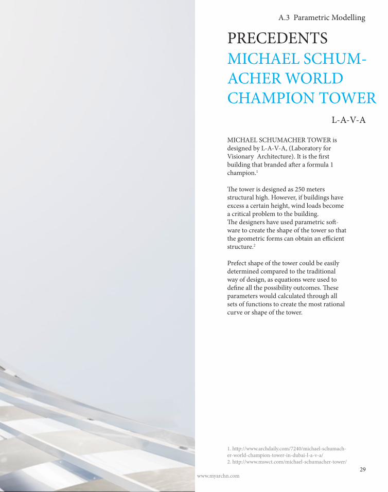
MICHAEL SCHUM-ACHER WORLD CHAMPION TOWER L-A-V-A
PRECEDENTS
www.myarchn.com
MICHAEL SCHUMACHER TOWER is designed by L-A-V-A, (Laboratory for Visionary Architecture). It is the first building that branded after a formula 1 champion.1
The tower is designed as 250 meters structural high. However, if buildings have excess a certain height, wind loads become a critical problem to the building. The designers have used parametric soft-ware to create the shape of the tower so that the geometric forms can obtain an efficient structure.2
Prefect shape of the tower could be easily determined compared to the traditional way of design, as equations were used to define all the possibility outcomes. These parameters would calculated through all sets of functions to create the most rational curve or shape of the tower.
1. http://www.archdaily.com/7240/michael-schumach-er-world-champion-tower-in-dubai-l-a-v-a/2. http://www.mswct.com/michael-schumacher-tower/

30
A.4 Algorithmic Explorations
ALGORITHMIC EXPLORATIONS
31
A.4 Algorithmic Explorations
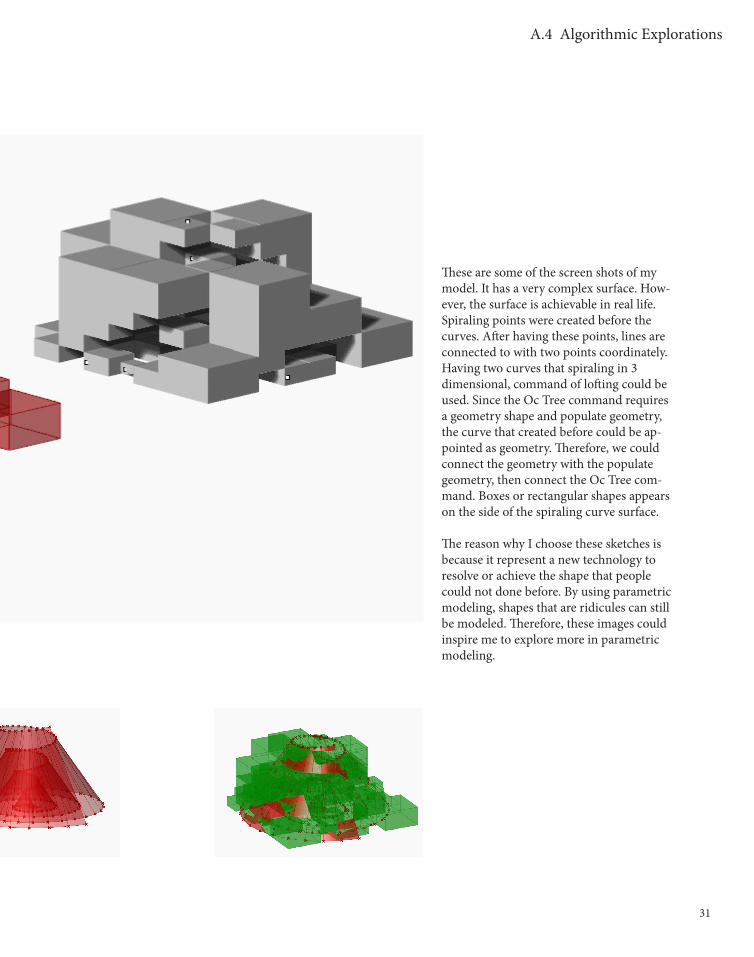
These are some of the screen shots of my model. It has a very complex surface. How-ever, the surface is achievable in real life. Spiraling points were created before the curves. After having these points, lines are connected to with two points coordinately. Having two curves that spiraling in 3 dimensional, command of lofting could be used. Since the Oc Tree command requires a geometry shape and populate geometry, the curve that created before could be ap-pointed as geometry. Therefore, we could connect the geometry with the populate geometry, then connect the Oc Tree com-mand. Boxes or rectangular shapes appears on the side of the spiraling curve surface.
The reason why I choose these sketches is because it represent a new technology to resolve or achieve the shape that people could not done before. By using parametric modeling, shapes that are ridicules can still be modeled. Therefore, these images could inspire me to explore more in parametric modeling.

32
A.5 Conclusion
As images are shown before, the sketch model of my design is based on a volcanic shape. Hollow inside the building, which provides an extremely large interior space. Rooms or patterns are located on the surface of the volcanic shape. The way it innovates is how rooms can be piled up together to create a large space.
The gateway project requires a project on the highway. It is impor-tant to provide enough space for cars to go through and stable struc-ture. Technique that used in this sketch model provides a way to do so. Therefore, it would be a good way to start practicing a solution towards a large traffic flow.
Moreover, by using the parametric modeling to finish this project, it could provide a new view for people from other discipline that architecture. People may experience a new technology through driv-ing pass. Structures, patterns may be a brand new idea for them.
CONCLUSION

33
A.6 Learning Outcomes
LEARNING OUTCOME
Computational architecture has become very familiar to us. Starting at year 1, virtual environment, digital fabrication has become one of the fast fabrications I have ever met. The term of parametric model-ing is strange for me at the first time, however, through the research and exercise that we’ve done in the first week, I’m now interested in how far can parametric modeling goes. What would be the boarder of it.
Possibility is one of the key words of computational architecture. Through the computer programming or parametric modeling, dif-ferent approaches could solve one problem. However, while facing multiple options, people must deeply considered before making the conclusion or decision.

34
B.1 Design Focus

35
B.1 Design Focus
DESIGN FOCUS: TESSELATION
The Western Gateway installation should provide an entry statement and arrival experience, and become a new identifier for the municipality. THe installation should create a focal point fo iconic scale and pre-sene and encourage a sense of pride within the local community. The Western Gateway should propose new, inspiring and brave ideas, to generate a new discourse.
The main stream of our group is tesselation. According to the understanding, tesselation is to construct a 3-dimensional objects by using 2-dimensional plane geometry. The object that we built would be a self-standing sructure with complex surface. In order to create such surface, analyzing the precedent work would be essential.
Voussoir Cloud’ by IwamotoScott with Buro Happold would be one of the precedent that related to our group project. IwamotoScott was trying to express the light and shadow effects during the different times within a day. It would be interesting to explore the possibility of having ever changing with light and shadows by doing computational scripts.
Voussair Cloud, IwamotoScoot
36

37
B.2 Case Studey 1.0
Among the provided Grasshopper difini-tions, ‘Voussoir Cloud’ by IwamotoScott with Buro Happold was chosen as a case study. The reason why this would be the case study 1.0 is because of its shape. The object itself was formed in dome shape with patterns on it and self-standing. The most critical point of this case study would be the self-standing part as the elements act as a structural element to support this object.
It would have very interesting outputs if imputs are vary as the definition would ma-nipulate the imputs to achieve a fantastic output.
In order to know more about the Grass-hopper commands, the definition was rewrited by changing the variables. By changing these factors, different shapes was created.
CASE STUDY 1.0
Voussair Cloud, IwamotoScoot
38
B.2 Case Studey 1.0
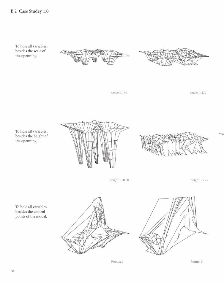
scale: 0.472scale: 0.150
height: -5.27height: -10.00
Points: 4 Points: 3
To hole all variables, besides the scale of the openning.
To hole all variables, besides the height of the openning.
To hole all variables, besides the control points of the model.
39
B.2 Case Studey 1.0
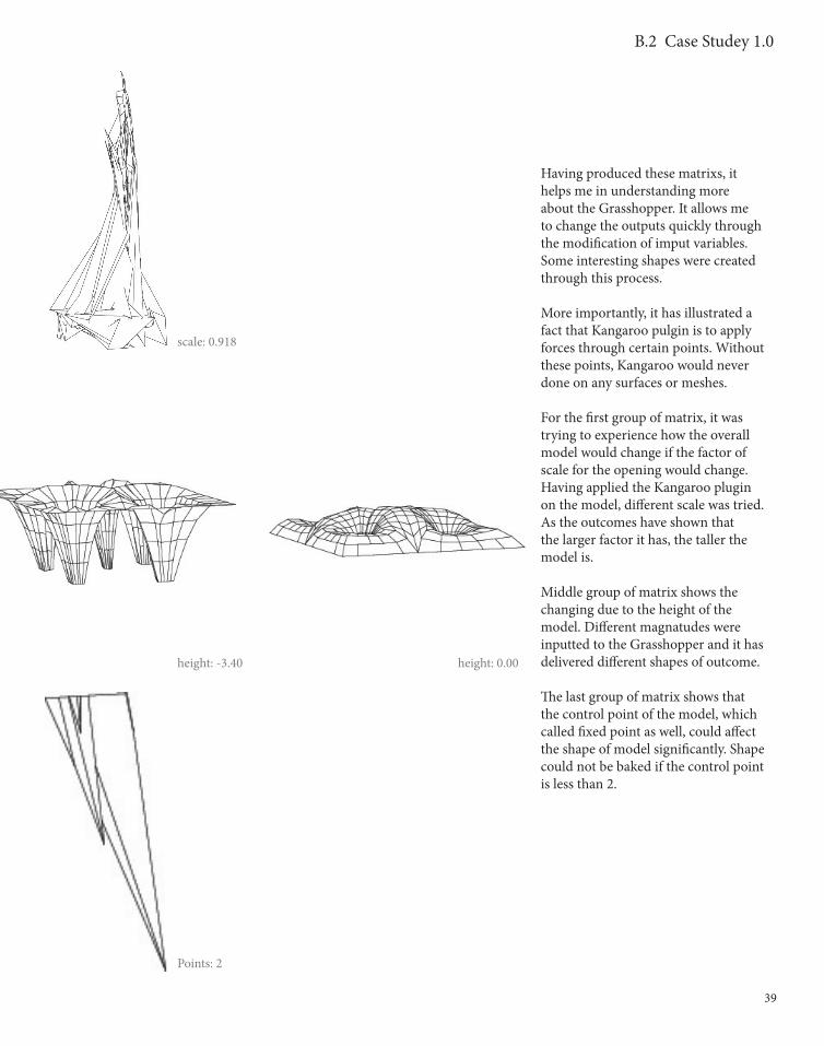
scale: 0.918
height: -3.40 height: 0.00
Points: 2
Having produced these matrixs, it helps me in understanding more about the Grasshopper. It allows me to change the outputs quickly through the modification of imput variables. Some interesting shapes were created through this process.
More importantly, it has illustrated a fact that Kangaroo pulgin is to apply forces through certain points. Without these points, Kangaroo would never done on any surfaces or meshes.
For the first group of matrix, it was trying to experience how the overall model would change if the factor of scale for the opening would change. Having applied the Kangaroo plugin on the model, different scale was tried. As the outcomes have shown that the larger factor it has, the taller the model is.
Middle group of matrix shows the changing due to the height of the model. Different magnatudes were inputted to the Grasshopper and it has delivered different shapes of outcome.
The last group of matrix shows that the control point of the model, which called fixed point as well, could affect the shape of model significantly. Shape could not be baked if the control point is less than 2.

40
B.2 Case Studey 1.0
To hole all variables, besides the quantity of fixed points. points: 4 points: 3
points: 4 points: 3
Plan View
Prespective View

41
B.2 Case Studey 1.0
Also, our group started to experience the possibilitiy of the surface. We were trying to make the surface in ten-sion so that it would look like it was pulling up on edges. By doing this, it illustrates the possibility of having dif-ferent forms of a rectangle.
The matrix that created shows the proccess of making the surface in ten-sion and tried to play around with the control point of the surface. Different quantity of points were tested and the surface could give people a sense of floating up towards the air.
points: 2 points: 1
points: 2 points: 1

42
B.3 Case Studey 2.0
43
B.3 Case Studey 2.0
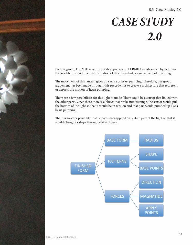
For our group, FERMID is our inspiration precedent. FERMID was designed by Behhnaz Babazadeh. It is said that the inspiration of this precedent is a movement of breathing.
Th e movement of this lantern gives us a sense of heart pumping. Th erefore, our group arguement has been made throught this precedent is to create a architecture that represent or express the motion of heart pumping.
Th ere are a few possibilities for this light to made. Th ere could be a sensor that linked with the other parts. Once there there is a object that broke into its range, the sensor would pull the bottom of the light so that it would be in tension and that part would pumped up like a heart pumping.
Th ere is another posibility that is forces may applied on certain part of the light so that it would change its shape through certain times.
CASE STUDY 2.0
FERMID, Behnaz Babazadeh
FINISHED FORM
BASE FORM RADIUS
PATTERNS
SHAPE
BASE POINTS
FORCES
DIRECTION
MAGNATIDE
APPLY POINTS
44
B.3 Case Studey 2.0
1
4 5
2
45
B.3 Case Studey 2.0
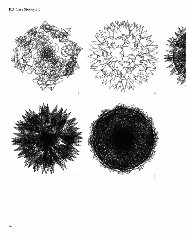
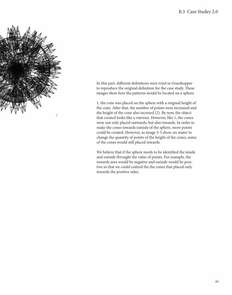
In this part, different definitions were tried in Grasshopper to reproduce the original definition for the case study. These images show how the patterns would be located on a sphere.
1. the cone was placed on the sphere with a original height of the cone. After that, the number of points were increased and the height of the cone also incresed (2). By now, the object that created looks like a vairious. However, like 1, the cones were not only placed outwards, but also inwards. In order to make the cones towards outside of the sphere, more points could be created. However, as image 3-5 show, no mater to change the quantity of points of the height of the cones, some of the cones would still placed inwards.
We believe that if the sphere needs to be identified the inside and outside throught the value of points. For example, the inwards area would be negative and outside would be posi-tive so that we could control the the cones that placed only towards the positive sides.
3

46
B.3 Case Studey 2.0

47
B.3 Case Studey 2.0
The matrix that we baked regualry show the processing of an-other possibility of the original definition. The matrix was quite successful as we could produce similar outcome compared to the orignial project. The shape of the patterns which attached on the basic shape of the original project were quite similar as well. By having done so far, out group knows how to produce different patterns that could attached to different shapes of base object. The next move for our project could exploring the difinition to create a movable surface.
48
B.4 Technique: Development

49
B.4 Technique: Development
TECHNIQUE: DEVELOPMENT
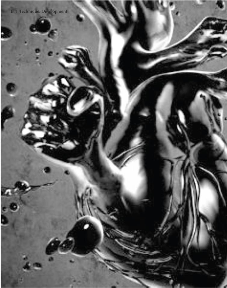
HEART-PUMPING
From case study 2.0, our group was amazed by the prec-edent FERMID, Behnaz Babazadeh. We were more likely to start look-ing at the technique that could provide movement to the object. Two apporaches were designed for the design theme, which is to capturing the movement and power of heart-pumping effect.
In order to achieve this outcome, a large quality of work should be done to search for a better outcome. After having the better outcomes, more needs to be considered and searching for another solution throught those better solution.
Eventually, only one or two solution could be left and we could develop more on these two apporaches.
For our group, two apporaches namely, Inflation and Motion were developed for expressing the idea of our design theme.

50
APPORACH 1: INFLATION
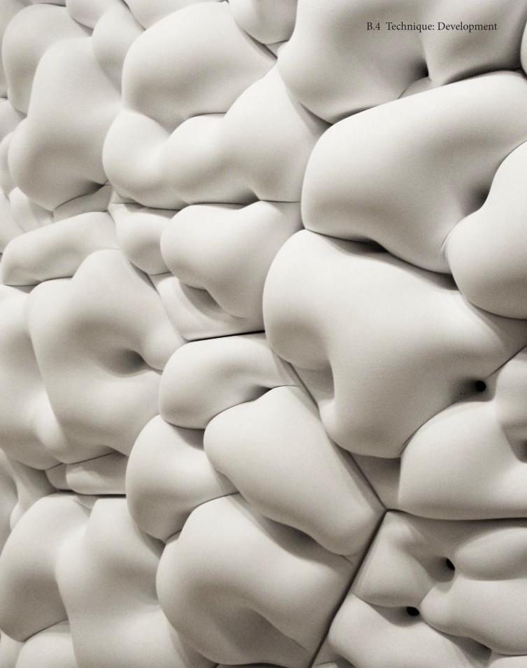
P-WALL, Andrew Kudless
P-Wall was a precedent that inspire our apporach. Lump-iness surface was used to represent the frozen movement of a strong energy within a object. The way how it was presented seems to be interesting and unique if is would applied on the surface of a building or our project.
In order to achieve this outcome, two plugins were used namely kangaroo and panelling tool. Unique elements on the surface are the key point of our design. In order to create the lumpiness of the surface, forces are applied on those modules by using kangaroo. After having the satisfied objects, we generated these elements into a self-standing structure. Panelling tool was used for searching a better distribution of elements.
Through this apporach, we wish to provide a feeling of excitement and dynamicity through the expression of the Gateway project installation, to introduce a ‘small pump’ as the starting of your fantastic journey in Melbourne City.
B.4 Technique: Development
51
B.4 Technique: Development
52
B.4 Technique: Development
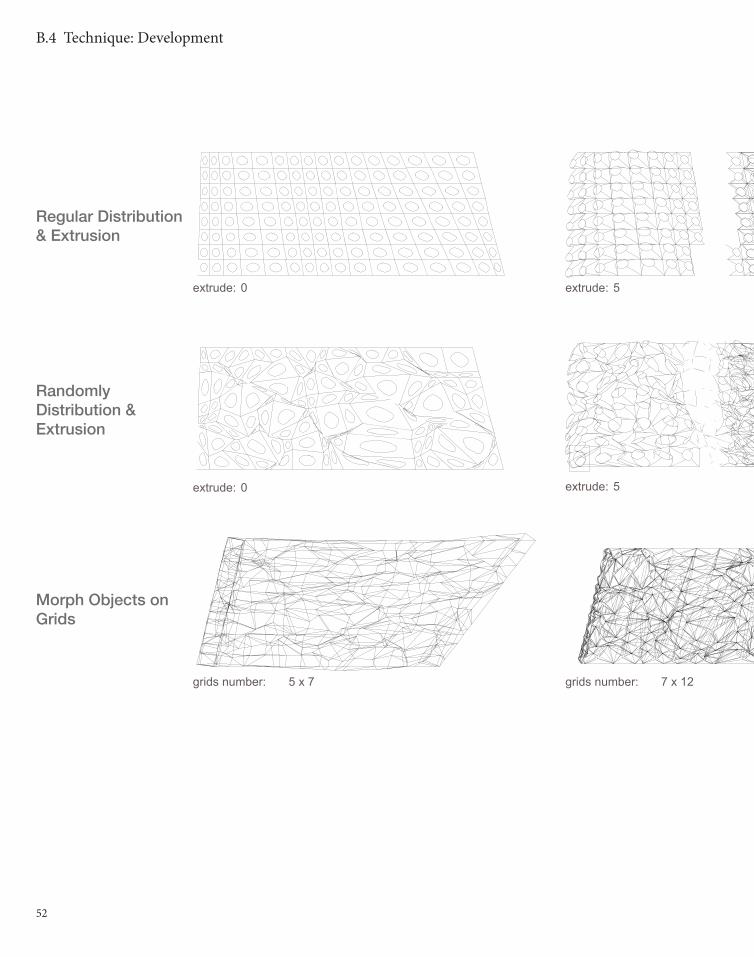
extrude: 0
extrude: 0
extrude: 5
extrude: 5
grids number: 7 x 12grids number: 5 x 7
Regular Distribution & Extrusion
Randomly Distribution & Extrusion
Morph Objects on Grids

53
B.4 Technique: Development
extrude: 10
extrude: 10
grids number: 9 x 17

54
B.4 Technique: Development
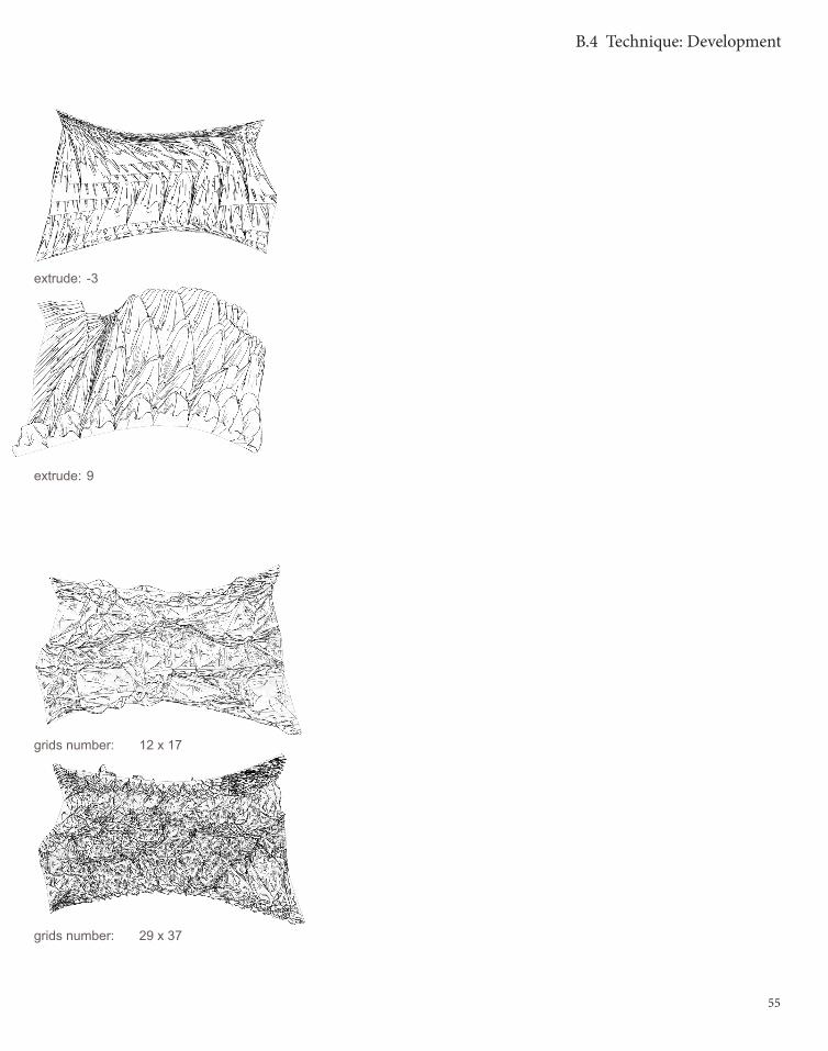
Morph Objects on Grids & Extrusion
Morph Randomly Distributed Objects on Grids
extrude: -9 extrude: -6
extrude: 3 extrude: 6
grids number: 9 x 12grids number: 5 x 7
grids number: 23 x29grids number: 17 x 23
55
B.4 Technique: Development
extrude: -3
extrude: 9
grids number: 12 x 17
grids number: 29 x 37

56
B.4 Technique: Development
57
B.4 Technique: Development
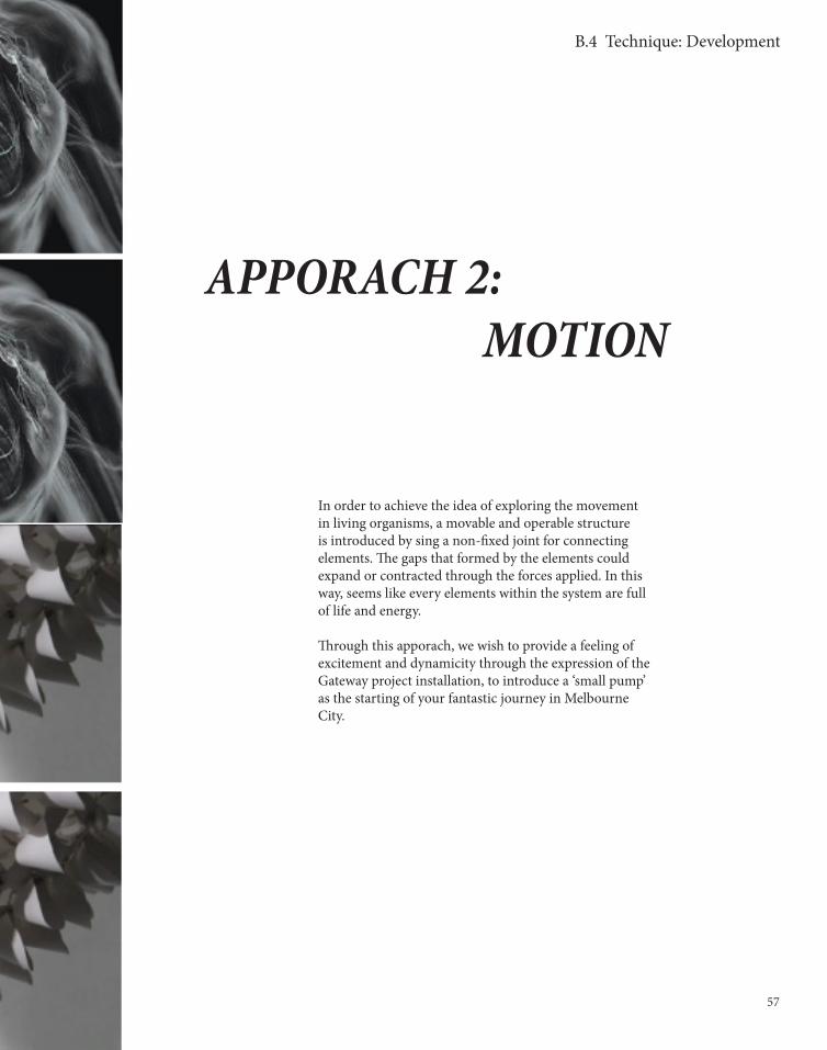
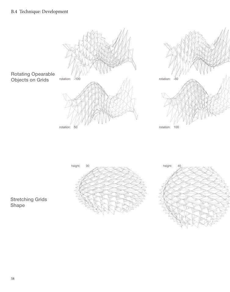
APPORACH 2: MOTION
In order to achieve the idea of exploring the movement in living organisms, a movable and operable structure is introduced by sing a non-fixed joint for connecting elements. The gaps that formed by the elements could expand or contracted through the forces applied. In this way, seems like every elements within the system are full of life and energy.
Through this apporach, we wish to provide a feeling of excitement and dynamicity through the expression of the Gateway project installation, to introduce a ‘small pump’ as the starting of your fantastic journey in Melbourne City.
58
B.4 Technique: Development
rotation: -100 rotation: -50
rotation: 50 rotation: 100
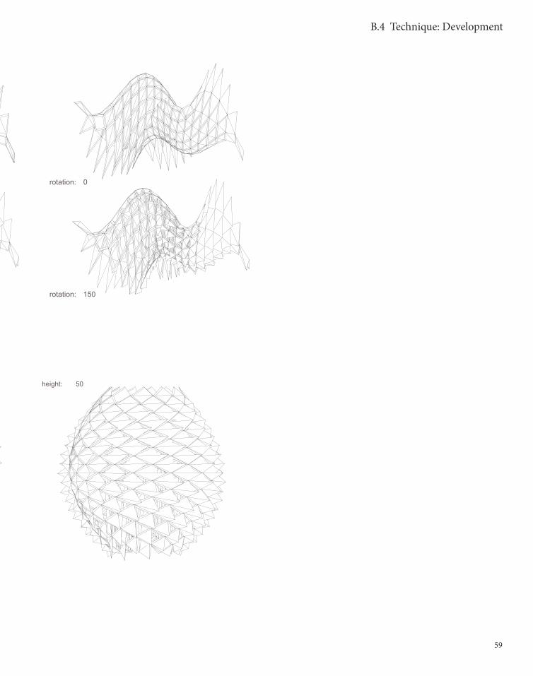
Rotating Opearable Objects on Grids
height: 30 height: 40
Stretching Grids Shape
59
height: 50
B.4 Technique: Development
rotation: 0
rotation: 150

60
B.4 Technique: Development
offset dinstance: 0
offset dinstance: -35
offset dinstance: -15
offset dinstance: -45
offset dinstance: 35 offset dinstance: 45
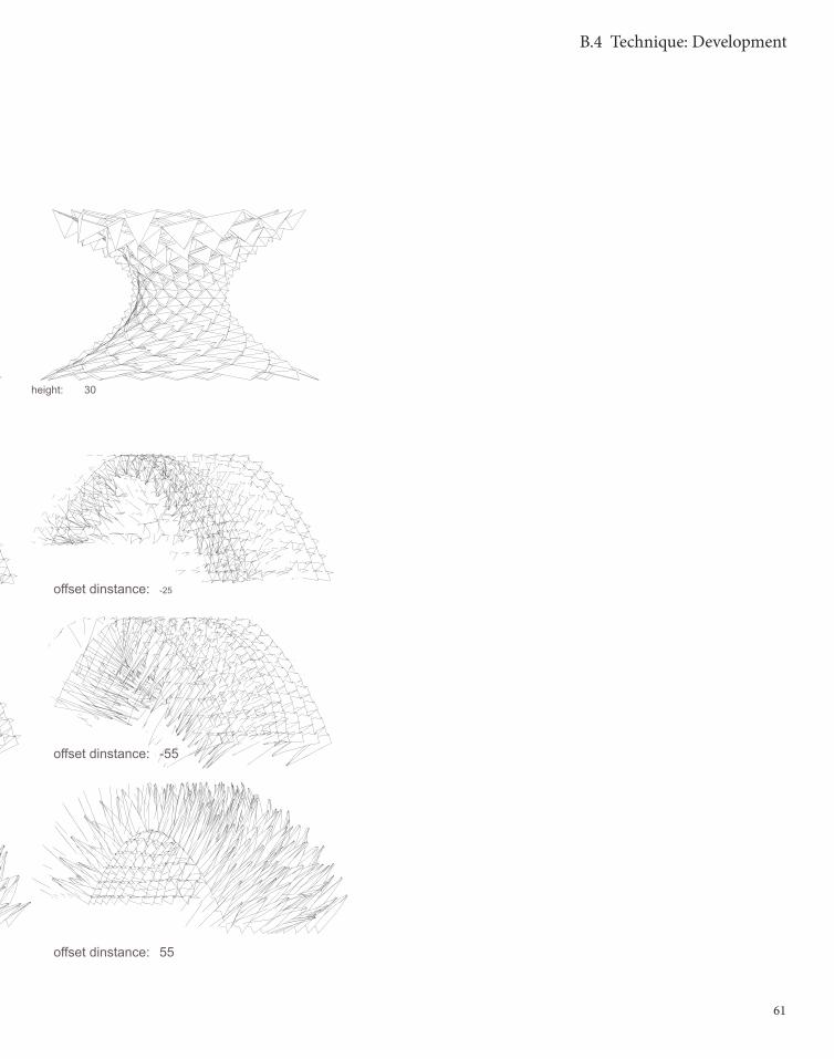
Movable Objects & Extrusion
height: 50 height: 40
Stretching Grids Shape
61
B.4 Technique: Development
offset dinstance: -25
offset dinstance: -55
offset dinstance: 55
height: 30
62
B.5 Technique: Prototypes

63
B.5 Technique: Prototypes
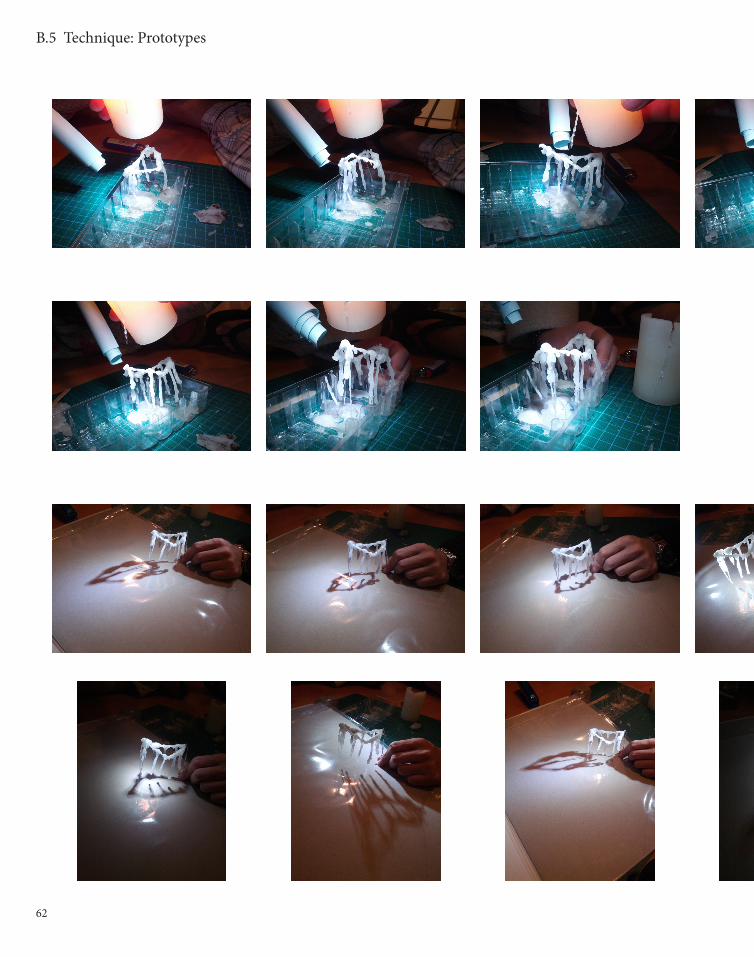
During the modeling making phase, more than 15 models were made to test the outcome of different material and different apporaches.
First of all, photos on the left are demon-strating the supporting of wax. By melting the wax, we were trying to find a most organic form. However, since wax needs a surface or object to wax on, a bended closed object is created. The melted wax could now form on this object. In order to increase the speed of solidification, one of the group member was trying to blow some cold air. After around 10mins of pulling wax, a base shape was created. The wax has formed many driping track.
This model was then taken for light effect as we are interesting the shadowing of models.
The last model was very successful as it shown the shadow of the wax and a little bit of light transperancy.
TECHNIQUE: PROTOTYPES

64
B.5 Technique: Prototypes
65
B.5 Technique: Prototypes
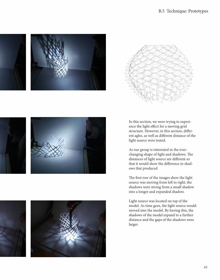
In this section, we were trying to experi-ence the light effect for a moving grid structure. However, in this section, differ-ent agles, as well as different distance of the light source were tested.
As our group is interested in the ever-changing shape of light and shadows. The distances of light source are different so that it would show the difference in shad-ows that produced
The first row of the images show the light source was moving from left to right, the shadows were mving from a small shadow into a longer and expanded shadow.
Light source was located on top of the model. As time goes, the light source would moved into the model. By having this, the shadows of the model expand to a further distance and the gaps of the shadows were larger.
66
B.5 Technique: Prototypes
67
B.5 Technique: Prototypes
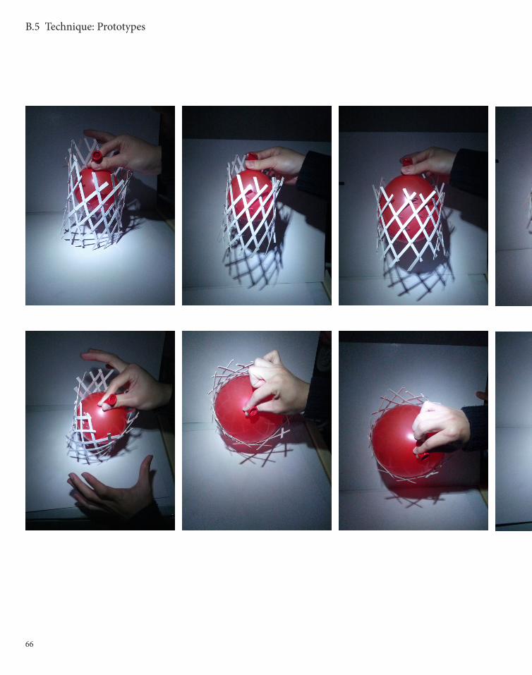
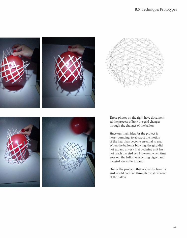
Those photos on the right have document-ed the process of how the grid changes through the changes of the ballon.
Since our main idea for the project is heart-pumping, to abstract the motion of the heart has become essential to use. When the ballon is blowing, the gird did not expand at very first begining as it has not reach the gird yet. However, when time goes on, the ballon was getting bigger and the gird started to expand.
One of the problem that occured is how the gird would contract through the shrinkage of the ballon.
68
B.5 Technique: Prototypes
69
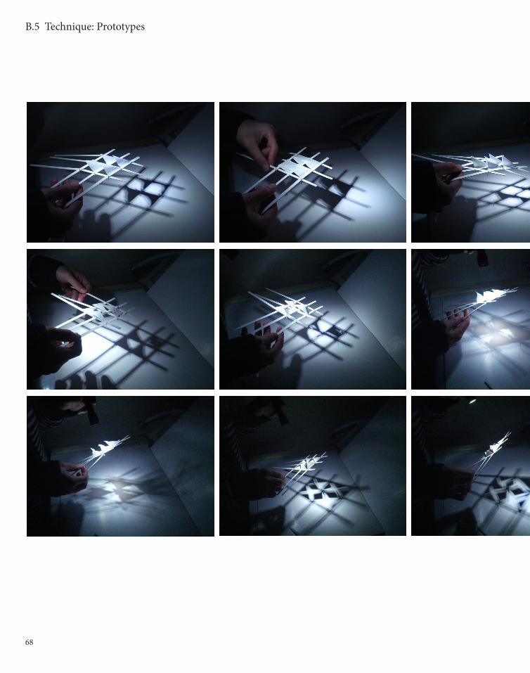
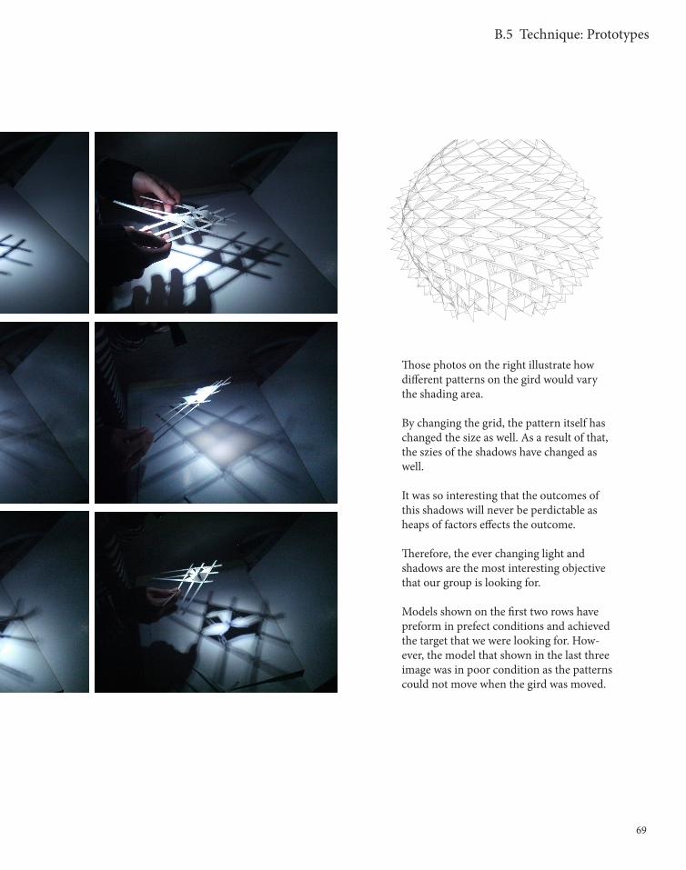
Those photos on the right illustrate how different patterns on the gird would vary the shading area.
By changing the grid, the pattern itself has changed the size as well. As a result of that, the szies of the shadows have changed as well.
It was so interesting that the outcomes of this shadows will never be perdictable as heaps of factors effects the outcome.
Therefore, the ever changing light and shadows are the most interesting objective that our group is looking for.
Models shown on the first two rows have preform in prefect conditions and achieved the target that we were looking for. How-ever, the model that shown in the last three image was in poor condition as the patterns could not move when the gird was moved.
B.5 Technique: Prototypes
70
B.5 Technique: Prototypes
71
B.5 Technique: Prototypes
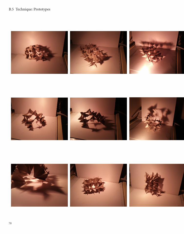
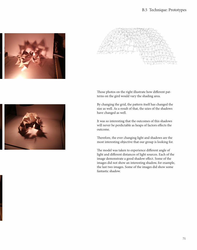
Those photos on the right illustrate how different pat-terns on the gird would vary the shading area.
By changing the grid, the pattern itself has changed the size as well. As a result of that, the szies of the shadows have changed as well.
It was so interesting that the outcomes of this shadows will never be perdictable as heaps of factors effects the outcome.
Therefore, the ever changing light and shadows are the most interesting objective that our group is looking for.
The model was taken to experience different angle of light and different distances of light sources. Each of the image demonstrate a good shadow effect. Some of the images did not show an interesting shadow, for example, the last two images. Some of the images did show some fantastic shadow.

72
B.5 Technique: Prototypes
73
B.5 Technique: Prototypes
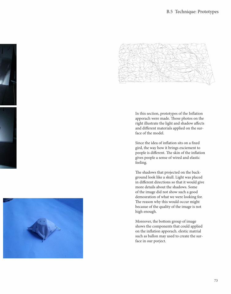
In this section, prototypes of the Inflation apporach were made. Those photos on the right illustrate the light and shadow affects and different materials applied on the sur-face of the model.
Since the idea of inflation sits on a fixed gird, the way how it brings exciement to people is different. The skin of the inflation gives people a sense of wired and elastic feeling.
The shadows that projected on the back-ground look like a skull. Light was placed in different directions so that it would give more details about the shadows. Some of the image did not show such a good demosration of what we were looking for. The reason why this would occur might becasue of the quality of the image is not high enough.
Moreover, the bottom group of image shows the components that could applied on the inflation apporach. elestic matrial such as ballon may used to create the sur-face in our porject.
74
B.6 Technique: Proposal
TECHNIQUE: PROPOSAL
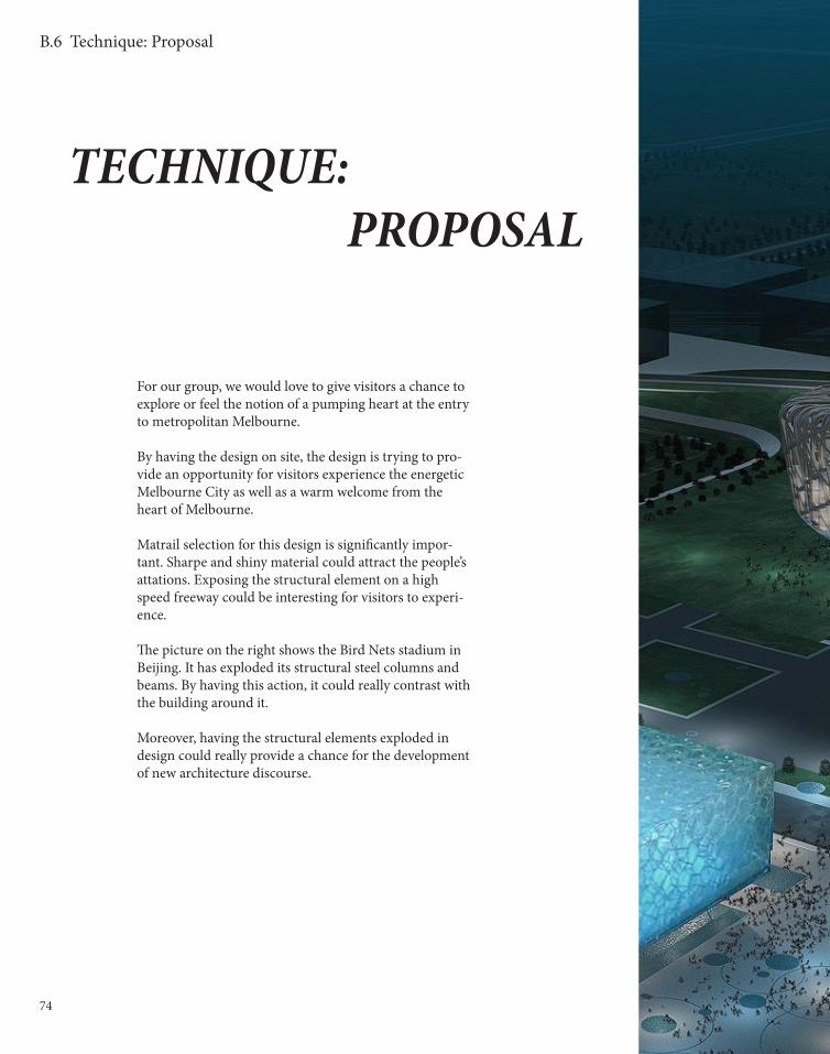
For our group, we would love to give visitors a chance to explore or feel the notion of a pumping heart at the entry to metropolitan Melbourne.
By having the design on site, the design is trying to pro-vide an opportunity for visitors experience the energetic Melbourne City as well as a warm welcome from the heart of Melbourne.
Matrail selection for this design is significantly impor-tant. Sharpe and shiny material could attract the people’s attations. Exposing the structural element on a high speed freeway could be interesting for visitors to experi-ence.
The picture on the right shows the Bird Nets stadium in Beijing. It has exploded its structural steel columns and beams. By having this action, it could really contrast with the building around it.
Moreover, having the structural elements exploded in design could really provide a chance for the development of new architecture discourse.

75
B.6 Technique: Proposal

76
B.7 Algorithmic Sketches
ALGORITHMIC SKETCHES
For me, it was a great time for me to develop my parametric modeling skills. Unlike the stu-dios that have done before, or even Virtual Environment, Studio Air provides a more compre-hensive way of digital design.
By using Grasshopper, my algorithmic logic has improved. Building some algorithm in Grass-hopper would not be impossible for me any more.
This subject also provide me another opportunity to see the real world. To see the process of design in architecture industry. Processes were changed from form designing to searching for form.
height: 50 height: 40 height: 30

77
B.8 Learning Objectives and Outcomes
LEARNING OUTCOME
After the mid-semester crit, many valued suggestions were recieved from the tutors and friends. Our group design was very interesting as it represented the movement and motion of a pumping heart. Dif-ferent materials have been used to tested the prototypes. However, most improvement could be done:
For inflation apporach, the elastic surface is very interesting as it could contract and expand through the forces applied. However, it would be more interesting if it would combined with the motion apporach. In other words, the elastic surface could be installed on to the movable grids.
For the motion apporach, it was very interesting to see the grid moved through the forces applied. However, as the heart is voilent, the material should elastic enough to expand and contract in a very short time.
One of the problems that our group need to solve is how the grid could contract with the ballon when the ballon shirnk. Sticking the ballon with the grid will not be a good idea as it did not allow voids for light and shadowing.
For the further development, combing these two apporaches would be sure. Ways of combining these two apporaches would be tested and solve within the group of three.