part i: introduction - university of minnesota · protocols: control sending, ......
TRANSCRIPT

1: Introduction 1
Part I: Introduction
Chapter goal:
get context, overview, “feel” of networking
more depth, detail later in course
approach:
descriptive
use Internet as example
Overview:
what’s the Internet
what’s a protocol?
network edge
network core
access net, physical media
performance: loss, delay
protocol layers, service models
backbones, NAPs, ISPs
history
ATM network

1: Introduction 2
What’s the Internet: “nuts and bolts” view
millions of connected computing devices: hosts, end-systems pc’s workstations, servers
PDA’s phones, toasters
running network apps
communication links fiber, copper, radio,
satellite
routers: forward packets (chunks) of data thru network
local ISP
companynetwork
regional ISP
router workstation
servermobile
1: Introduction 3
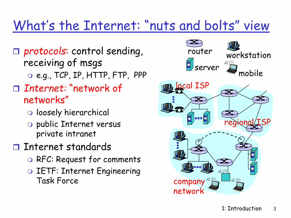
What’s the Internet: “nuts and bolts” view
protocols: control sending, receiving of msgs e.g., TCP, IP, HTTP, FTP, PPP
Internet: “network of networks” loosely hierarchical
public Internet versus private intranet
Internet standards RFC: Request for comments
IETF: Internet Engineering Task Force
local ISP
companynetwork
regional ISP
router workstation
servermobile

1: Introduction 4
What’s the Internet: a service view
communication infrastructure enables distributed applications: WWW, email, games, e-
commerce, database., voting,
more?
communication services provided: connectionless
connection-oriented
cyberspace [Gibson]:“a consensual hallucination
experienced daily by billions of operators, in every nation, ...."

1: Introduction 5
What’s a protocol?
human protocols:
“what’s the time?”
“I have a question”
introductions
… specific msgs sent
… specific actions taken when msgs received, or other events
network protocols:
machines rather than humans
all communication activity in Internet governed by protocols
protocols define format, order of msgs sent and received among network
entities, and actions taken on msg
transmission, receipt

1: Introduction 6
What’s a protocol ?
a human protocol and a computer network protocol:
Q: Other human protocol?
Hi
Hi
Got thetime?
2:00
TCP connectionreq.
TCP connectionreply.
Get http://gaia.cs.umass.edu/index.htm
<file>
time

1: Introduction 7
A closer look at network structure:
network edge:applications and hosts
network core: routers
network of networks
access networks, physical media:communication links
1: Introduction 8
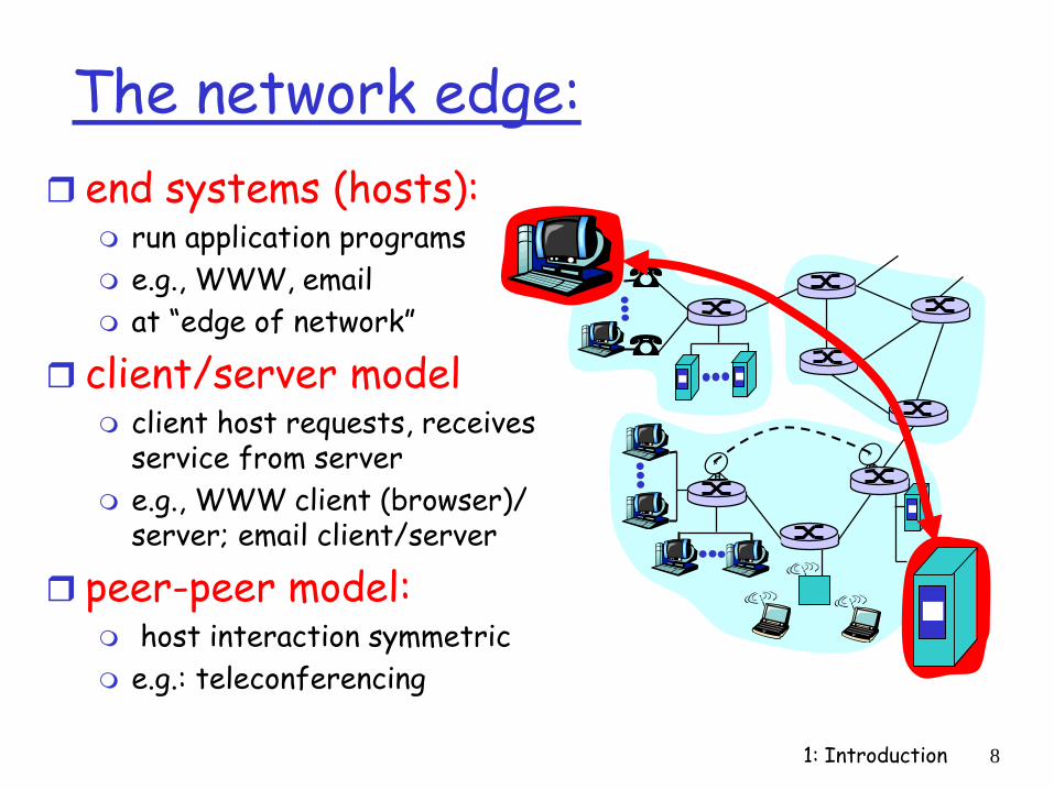
The network edge:
end systems (hosts): run application programs
e.g., WWW, email
at “edge of network”
client/server model client host requests, receives
service from server
e.g., WWW client (browser)/ server; email client/server
peer-peer model: host interaction symmetric
e.g.: teleconferencing
1: Introduction 9
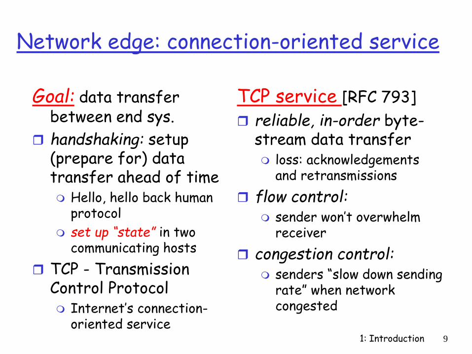
Network edge: connection-oriented service
Goal: data transfer between end sys.
handshaking: setup (prepare for) data transfer ahead of time Hello, hello back human
protocol
set up “state” in two communicating hosts
TCP - Transmission Control Protocol Internet’s connection-
oriented service
TCP service [RFC 793]
reliable, in-order byte-stream data transfer loss: acknowledgements
and retransmissions
flow control: sender won’t overwhelm
receiver
congestion control: senders “slow down sending
rate” when network congested

1: Introduction 10
Network edge: connectionless service
Goal: data transfer between end systems same as before!
UDP - User Datagram Protocol [RFC 768]: Internet’s connectionless service
unreliable data transfer
no flow control
no congestion control
App’s using TCP: HTTP (WWW), FTP
(file transfer), Telnet (remote login), SMTP (email)
App’s using UDP: streaming media,
teleconferencing, Internet telephony

1: Introduction 11
Why VIA –Hardware structure
CPU CPU
MemoryController
PCI Bridge
Memory
PCI Bus
SCSI Ethernet FC
SANLAN
Disk
Disk
Disk

1: Introduction 12
A Case for Data and Control Flow between Host and NIC

1: Introduction 13
The Network Core
mesh of interconnected routers
the fundamental question: how is data transferred through net?
circuit switching:dedicated circuit per call: telephone net
packet-switching: data sent thru net in discrete “chunks”
1: Introduction 14
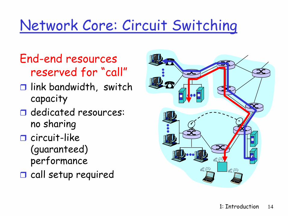
Network Core: Circuit Switching
End-end resources reserved for “call”
link bandwidth, switch capacity
dedicated resources: no sharing
circuit-like (guaranteed) performance
call setup required

1: Introduction 15
Internet Architecture
LANs
International
lines
ISP ISPcompany university
national
network
regional
network
NAP
on-line
services
companyaccess via
modem
1: Introduction 16
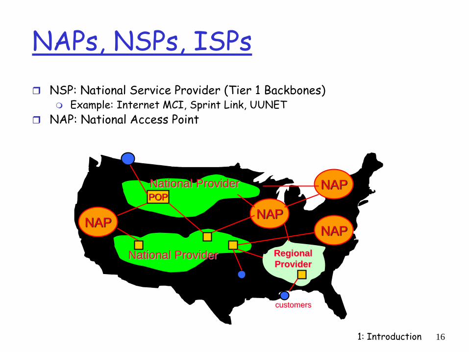
NAPs, NSPs, ISPs
NSP: National Service Provider (Tier 1 Backbones) Example: Internet MCI, Sprint Link, UUNET
NAP: National Access Point
NAPNAP
NAP
NAP
National Provider
National Provider Regional
Provider
POP
customers

1: Introduction 17
NAP and Private Peering

1: Introduction 18
InternetNetwork
Leveraging Sprint’s SONET-based, gigabit
switch Internet backbone
PrivatePeering
PrivatePeering
PrivatePeering
MAE-WestExchange Point
Pacific BellExchange Point
PrivatePeering Ameritech
Exchange Point
PrivatePeering
PrivatePeering
SprintExchange Point
PrivatePeering
MAE-EastExchange Point
PrivatePeering

1: Introduction 19
Network Core: Circuit Switching
network resources (e.g., bandwidth) divided into “pieces”
pieces allocated to calls
resource piece idle if not used by owning call (no sharing)
dividing link bandwidth into “pieces”
frequency division
time division

1: Introduction 20
Network Core: Packet Switching
each end-end data stream divided into packets
user A, B packets sharenetwork resources
each packet uses full link bandwidth
resources used as needed,
resource contention:
aggregate resource demand can exceed amount available
congestion: packets queue, wait for link use
store and forward: packets move one hop at a time
transmit over link
wait turn at next link
Bandwidth division into “pieces”
Dedicated allocation
Resource reservation
1: Introduction 21
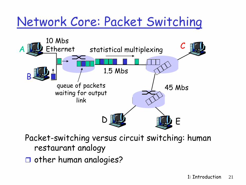
Network Core: Packet Switching
Packet-switching versus circuit switching: human restaurant analogy
other human analogies?
A
B
C10 MbsEthernet
1.5 Mbs
45 Mbs
D E
statistical multiplexing
queue of packetswaiting for output
link

1: Introduction 22
Network Core: Packet Switching
Packet-switching:
store and forward behavior

1: Introduction 23
Packet switching versus circuit switching
1 Mbit link
each user: 100Kbps when “active”
active 10% of time
circuit-switching: 10 users
packet switching: with 35 users,
probability > 10 active less that .004
Packet switching allows more users to use network!
N users
1 Mbps link

1: Introduction 24
Packet switching versus circuit switching
Great for bursty data
resource sharing
no call setup
Excessive congestion: packet delay and loss
protocols needed for reliable data transfer, congestion control
Q: How to provide circuit-like behavior?
bandwidth guarantees needed for audio/video apps
still an unsolved problem (chapter 6)
Is packet switching a “slam dunk winner?”

1: Introduction 25
Packet-switched networks: routing
Goal: move packets among routers from source to destination we’ll study several path selection algorithms (chapter 4)
datagram network: destination address determines next hop
routes may change during session
analogy: driving, asking directions
virtual circuit network: each packet carries tag (virtual circuit ID), tag
determines next hop
fixed path determined at call setup time, remains fixed thru call
routers maintain per-call state

1: Introduction 26
Access networks and physical media
Q: How to connection end systems to edge router?
residential access nets
institutional access networks (school, company)
mobile access networks
Keep in mind:
bandwidth (bits per second) of access network?
shared or dedicated?

1: Introduction 27
Residential access: point to point access
Dialup via modem
up to 56Kbps direct access to router (conceptually)
ISDN: intergrated services digital network: 128Kbps all-digital connect to router
ADSL: asymmetric digital subscriber line
up to 1 Mbps home-to-router
up to 8 Mbps router-to-home
ADSL deployment: UPDATETHIS

1: Introduction 28
Residential access: cable modems
HFC: hybrid fiber coax asymmetric: up to 10Mbps
upstream, 1 Mbps downstream
network of cable and fiber attaches homes to ISP router shared access to router
among home
issues: congestion, dimensioning
deployment: available via cable companies, e.g., MediaOne

1: Introduction 29
Institutional access: local area networks
company/univ local area network (LAN) connects end system to edge router
Ethernet:
shared or dedicated cable connects end system and router
10 Mbs, 100Mbps, Gigabit Ethernet
deployment: institutions, home LANs soon
LANs: chapter 5

1: Introduction 30
Wireless access networks
shared wireless access network connects end system to router
wireless LANs: radio spectrum replaces
wire
e.g., Lucent Wavelan 10 Mbps
wider-area wireless access CDPD: wireless access to
ISP router via cellular network
basestation
mobilehosts
router

1: Introduction 31
Physical Media
physical link:transmitted data bit propagates across link
guided media: signals propagate in
solid media: copper, fiber
unguided media: signals propagate
freelye.g., radio
Twisted Pair (TP)
two insulated copper wires Category 3: traditional
phone wires, 10 Mbps ethernet
Category 5 TP: 100Mbps ethernet

1: Introduction 32
Physical Media: coax, fiber
Coaxial cable: wire (signal carrier)
within a wire (shield) baseband: single channel
on cable
broadband: multiple channel on cable
bidirectional
common use in 10Mbs Ethernet
Fiber optic cable: glass fiber carrying
light pulses
high-speed operation: 100Mbps Ethernet
high-speed point-to-point transmission (e.g., 5 Gps)
low error rate

1: Introduction 33
Physical media: radio
signal carried in electromagnetic spectrum
no physical “wire”
bidirectional
propagation environment effects: reflection
obstruction by objects
interference
Radio link types: microwave
e.g. up to 45 Mbps channels
LAN (e.g., waveLAN) 2Mbps, 11Mbps
wide-area (e.g., cellular) e.g. CDPD, 10’s Kbps
satellite up to 50Mbps channel (or
multiple smaller channels)
270 Msec end-end delay
geosynchronous versus LEOS
1: Introduction 34
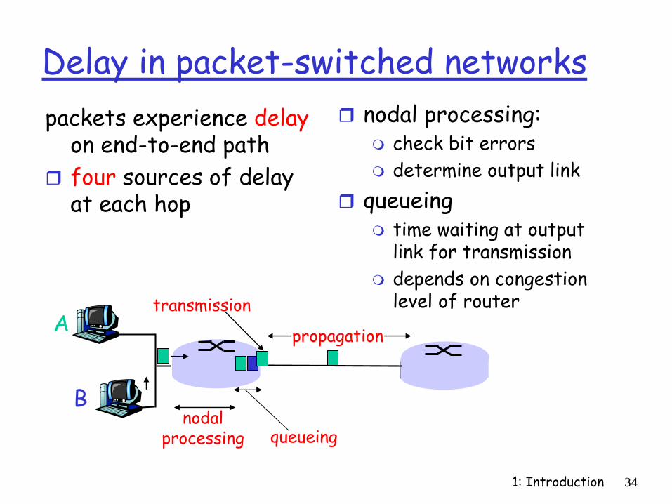
Delay in packet-switched networks
packets experience delay on end-to-end path
four sources of delay at each hop
nodal processing: check bit errors
determine output link
queueing time waiting at output
link for transmission
depends on congestion level of router
A
B
propagation
transmission
nodalprocessing queueing

1: Introduction 35
Delay in packet-switched networks
Transmission delay:
R=link bandwidth (bps)
L=packet length (bits)
time to send bits into link = L/R
Propagation delay:
d = length of physical link
s = propagation speed in medium (~2x10⁸ m/sec)
propagation delay = d/s
A
B
propagation
transmission
nodalprocessing queueing
Note: s and R are very different quantitites!

1: Introduction 36
Queueing delay (revisited)
R=link bandwidth (bps)
L=packet length (bits)
a=average packet arrival rate
traffic intensity = La/R
La/R ~ 0: average queueing delay small
La/R -> 1: delays become large
La/R > 1: more “work” arriving than can be serviced, average delay infinite!

1: Introduction 37

1: Introduction 38

1: Introduction 39

1: Introduction 40

1: Introduction 41

1: Introduction 42

1: Introduction 43