part iii: feasibility study c: new landfill site survey...
TRANSCRIPT

PART III: FEASIBILITY STUDY
C: NEW LANDFILL SITE SURVEY

Supporting Report
Chapter III-C
The Master Plan on Solid Waste Management
for Boracay Island and Malay Municipality
III-C-1
PART III-C: NEW LANDFILL SITE SURVEY
1 Introduction
Boracay Island is one of the popular tourist resorts in the Philippines and the number of
visitors has increased year by year and the amount of solid waste generated has rapidly
increased and become one of the most serious problems on the Island. Following RA9003,
the MOM closed the dumping site on Boracay Island and they try to develop a new Sanitary
Landfill (SLF) in Brangay Kabulihan. This part includes the results of series of surveys for
the development of the Kabulihan SLF.
2 Objectives
The site survey aimed to provide sufficient information and data necessary for the planning
for the SLF. Specifically, the objectives of the survey on the new SLF are:
- To generate topographic, cross-sections and longitudinal profiles of the site,
- To establish the geological setting of the site including seismic condition,
- To determine the nature and characteristics of the geological strata,
- To obtain surface water quality upstream, downstream and within the site and
groundwater quality at the site both during dry and wet seasons,
- To obtain the presence of landfill gases and record odor at and adjacent to the site,
- To document other relevant environmental conditions including ecological conditions,
- To prepare conceptual design of the new SLF as desk study for the feasibility study,
- To estimate the cost of the development of new SLF,
- To complete an environmental assessment, including appropriate mitigation measures
and a suitable management program, and
- Drafting of the report amended from the existing IEE Report.
3. Scope of Works
The survey covered four major components. These were: 1) Topographic Survey, 2)
Geological and Geotechnical Survey, 3) Environmental Survey and 4) Desk Study.
3.1 Topographic Survey
The survey consists of ground control and leveling surveys, with sufficient data points
acquired to prepare appropriate and accurate topographic maps, longitudinal profiles and
cross-sections. National Grid coordinates and an elevation system referenced to mean sea
level were used.
Establishment of permanent bench marks, also referenced to national grid at the site on
exposed bedrock or permanent structures. Surveying of the entire area is conducted by
using a total station and by indicating all identifiable objects/structures on the ground like
boreholes, groundwater wells, buildings, etc.
Supporting Report
Chapter III-C
The Master Plan on Solid Waste Management
for Boracay Island and Malay Municipality
III-C-2
3.2 Geological and Geotechnical Survey
- A desk-based study, to acquire and collate relevant background information in
conjunction with the environmental survey.
- A field based study, including field reconnaissance, intrusive site investigations, sample
recovery and laboratory testing.
- Investigation of all the available soil profiles and geological information of the site and
conduct sufficient field reconnaissance.
- Borehole drilling, sample recovery and subsequent laboratory testing, and installation of
ground water monitoring wells.
Set out and record the precise location and elevation of the top of each borehole and
groundwater monitoring wells, reference to national grid and mean sea level.
3.3 Environmental Survey
- Conduct a desk-based study, to acquire and collate relevant background information in
conjunction with the geological survey; and
- A field-based study, including field reconnaissance, site investigations, sample recovery
and laboratory testing and water quality test, meteorological measurement,
hydrological and hydro-geological survey, other physical and natural environment survey,
social condition survey; and support of public consultation
3.4 Desk Study
Conceptual design for the proposed SLF based upon the produced topographical map and
taking into consideration the geological, soil and environmental conditions of the site
includes following works:
- description of landfill type to be constructed including comparison of technical
alternatives
- facilities to be incorporated in the design (locations of the facilities shall be shown on the
layout plans)
- estimation of the capacities of the total landfill site and the proposed individual facilities
- preparation of development schedule, including any necessary land and dwelling
acquisition, and other official procedures including Environmental Compliance and
Certificate (ECC) procedures
- estimation of development costs based upon the derived bills of quantity, and
preparation of scaled and dimensioned drawings and layout plans.
4. Methodologies
4.1 Topographic Survey
4.1.1 Reconnaissance Survey and Coordination
As an initial activity, and to familiarize with the site condition as well as to ensure the safety

Supporting Report
Chapter III-C
The Master Plan on Solid Waste Management
for Boracay Island and Malay Municipality
III-C-3
of personnel and equipment, the survey team undertook a brief reconnaissance survey in
each site. Coordination with the local officials of Barangay Kabulihan was undertaken.
During the reconnaissance survey, locations of the control stations established by the
National Mapping and Resource Information Authority (NAMRIA), Philippine Coast and
Geodetic Survey (PCGS) or the Philippine Reference System (PRS) were also identified.
4.1.2 Establishment of Horizontal and Vertical Control
From the NAMRIA/PCGS control stations with known established positions and elevations,
permanent bench marks were established around the area for horizontal and vertical control.
From these secondary control stations, all the survey points (topographic & cross-section)
were observed. A high precision Global Positioning System (GPS) instrument was used to
establish both the positions and elevations of the secondary control points that were used
throughout the survey works.
4.1.3 Planimetric and Contour/Topographic Survey
Using a Total Station Instrument, oriented to a direction/data earlier from the GPS, all
positions where the data points were observed and recorded in a data logger, the following
the changes of the ground surface or landscape. In order to produce a planimetric and
contour map with the required contour interval, the density and distribution of spot elevation
were observed as many as possible. All planimetric features and structures which are
visible or identifiable or interpretable from the ground including land use features, trails,
boundaries of wooded areas, fences, orchards, buildings, roads, municipalities, cities and
other features were surveyed, measured and recorded. Eight cross-section/profile survey is
conducted across and along the slopes at 10 meters interval.
4.2 Geological and Geotechnical Survey
Basically, surface and sub-surface geological investigation is the scope of work undertaken
which involve geologic survey by Brunton compass and meter tape method and core drilling
of eight (8) bore holes, drilling of four (4) groundwater observation wells, excavation of six
(6) test pits and infiltration test of four (4) sites.
This report incorporates all the field procedures and results adopted in the investigation. It
is believed that the level of information is sufficient to judge the engineering properties of
the overlying and underlying foundation materials.
4.2.1 Drilling and Core Sampling Methodology
The drill hole is advanced through overburden materials by wash boring and by dry coring
method. To start, short piece casing is driven into the ground that also prevents the collapse
of the overburden materials. The casing is normally cleaned up by means of a chopping bit
attached to the lower end of the drill string. Drill rods are added to the drill string as the
depth of boring increases. Casing are also driven to prevent the collapse of the boreholes at

Supporting Report
Chapter III-C
The Master Plan on Solid Waste Management
for Boracay Island and Malay Municipality
III-C-4
sections of unstable soil is located.
When drilling is encountered the weathered bedrock, normally rotary drilling /coring
operation is conducted by using the conventional NQ series double tube type core barrel with
impregnated core diamond bits.
Extrusion of the core samples from the inner core barrel is made carefully. All core samples
retrieved are carefully placed and arranged in standard, properly made wooden core boxes
with cover according to depth provided with wooden spacers, to mark the beginning and
end of each drill runs. The lengths of cores recovered are measured over the core run
employed in order to come up with a recovery ratio expressed as Percentage Core Recovery.
4.2.2 Standard Penetration Test Methodology
Standard Penetration Test (SPT) was conducted in soft overburden materials, at every one (1)
m interval in soil and weathered rock layers. It was performed by using a standard
split-spoon sampler having 2” (50mm) OD and about 71 cm length. The split-spoon
sampler was attached at the bottom of string of AW rods. It is driven into the entire depth
of the sampling section (except when refusal is recorded within the section) by means of a
140 lb hammer free-falling along a guide rod from height of 76 cm onto a jar plate connected
at the top of the string of AW rods. This procedure was carried out by using automatic
tripping mechanism. It is driven to an initial penetration of 6 inches to by pass the
disturbed soil materials at the top of the sampling section. The number of blow counts for
the seating drive was recorded. The sampler is then advanced another 12 inches and the
corresponding number of blow counts for each 6 inches of penetration is recorded. The
total number of blow counts for the last 12 inches of penetration is known as the standard
penetration resistance (N-value) of the soil. Correlation has been developed between the
SPT N-value and soil parameters, which can be used for bearing capacity estimation.
Tables C.4.2-1 and C.4.2-2 show the correlation between the granular and cohesive soil and
the penetration resistance (N-value) recorded.
Table C.4.2-1 Correlation Between SPT and Soil Consistency for Granular Soil
Description Very Loose Loose Medium Dense Very DenseRelative Density Dr. 0-0.15 0.15-0.35 0.35- 0.65 0.65-0.85 0.85-1.00 Standard Penetration Test #N-Value 0-4 5-10 11-30 31-50 51 Up
Approx. Angle of Internal Friction Angle 250-280 280-300 300-350 350-400 400-430
Approx. Range of Moist Unit Weight, (KN/m3) 11.0-15.7 14.1-18.1 17.3-20.4 18.3-22.0 20.4-23.6
Submerged Unit Weight (KN/m3) 9.4 8.6-10.2 9.4-11.0 10.2-13.4 11.8
Source: JICA Study Team

Supporting Report
Chapter III-C
The Master Plan on Solid Waste Management
for Boracay Island and Malay Municipality
III-C-5
Table C.4.2-2 Correlation Between SPT and Soil Consistency for Cohesive Soil
Description Very soft Soft Medium Stiff Very Stiff Hard Unconfined Compressive Strength, Qu (KN/m2) 0-23.9 23.9-47.9 47.9-95.8 95.8-191.6 191.6-383.1 383 -UP
Standard Penetration Test #N 0-2 3-4 5-8 9-16 17-32 33-UP
Approx. Range of Standard Unit Weight, Saturated (KN/m3)
15.7-18.9 15.7-20.4 18.9-22.0 20.4 +
Source: JICA Study Team
After the conduct of the SPT on each test interval, the string of rods and split-spoon sampler
are pulled out of the hole and the recovered disturbed sample is retrieved and placed in a
moisture tight plastic bag for further visual examination and laboratory tests.
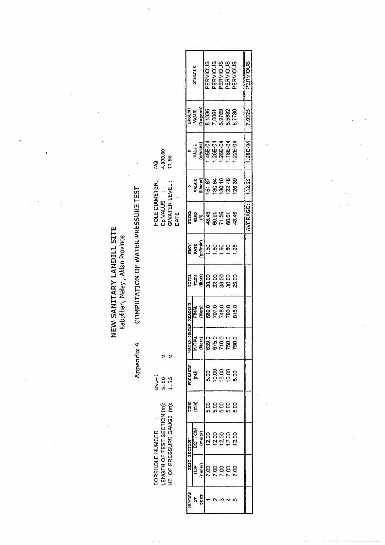
4.2.3 Permeability Test Methodology
(1) Water Pressure Test
In bedrock water pressure tests is conducted by descending method or using single packer
assembly. The descending method is normally performed on boreholes drilled in broken
ground or when there is danger of hole cave-in after drilling and washing. In addition,
percolation tests were conducted on particular test sections of selected boreholes where water
pressure cannot be established.
In the descending method, after drilling through the bottom of the test section desired, the
drilling water is made to dissipate into the rock for at least 24 hours. The static
groundwater level is measured together with the hole size and length of the packer assembly.
Then the core barrel and string of drill rods are pulled out and the packer assembly is
lowered down. The single rubber packer is set on the top of the test section. The section to
be tested and the corresponding height of the instrument are recorded. The water inflow is
determined from the water meter readings made at 5 minutes interval for all of the stages.
The applied pressure is dependent on the depth of test section and the nature of the
encountered bedrock.
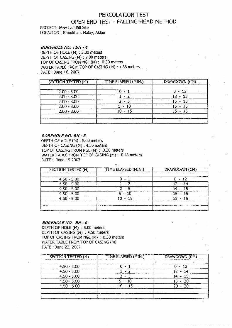
(2) Percolation Test
Permeability test by open-end falling head method was performed in overburden formation.
Hole advance was made either wash boring, rotary drilling or by use of chopping bit. Hole
advance was made at any desired depth depending on the layer to be tested. Hole was
properly cleaned to remove fine particles that could affect the permeability of the material.
Before the start of the tests, the depth of casing, size of the casing, groundwater level and
length of the open hole was recorded:
Fill the casing with water. Record time (To = 0) and drawdown (Ho = 0). Let the water in
casing drop , measuring the drawdown at regular time or depth interval (t1,H1; t2, H2; t3,
H3) until the water level is constant.

Supporting Report
Chapter III-C
The Master Plan on Solid Waste Management
for Boracay Island and Malay Municipality
III-C-6
4.2.4 Infiltrometer Test Methodology
Field permeability using infiltrometer cylinder (25cm dia. x 35.7 H) was conducted on soil
covering inside the proposed site of new SLF. Before testing layers with organic was
stripped and than press the infiltrometer into ground of about 20cm. Filled with clean water
the infiltrometer cylinder and then note the drawdown of water inside the cylinder for 2min.,
5min., 8min., 10min., 15min., until within 2 hour period.
4.3 Environmental Survey
4.3.1 Water Environment
(1) Water Quality for Surface Water and Groundwater
Water quality monitoring was programmed both for surface and groundwater. In shallow
stream, water is collected using a bucket until the desires volume of sample is attained.
After sampling, the containers of each sample were properly labeled/coded to identify the
location, date and time of sampling. Standard volume of samples, types of containers and
preservation were strictly followed. The required storage or preservation time of samples,
which normally depends on the transportation time to the laboratory was strictly followed.
The monitoring sites are shown in Figure C.4.3.1 while the parameters monitored are
summarized in Table C.4.3-1.
Table C.4.3-1 Parameters for Water Quality
1 Temperature(on-site observation) 14 Sulphate
2 pH (on-site observation) 15 Sodium
3 Color 16 Potassium
4 Turbidity 17 Calcium
5 DO 18 Magnesium
6 TSS 19 Iron
7 TDS 20 Lead
8 Conductivity (on-site observation) 21 Copper
9 Oil/Grease 22 Cadmium
10 BOD5 23 Chromium
11 COD 24 Total Mercury
12 Chloride as CL 25 Organo-Phosphate
13 Ammonia Nitrogen 26 Total coliform count

Supporting Report
Chapter III-C
The Master Plan on Solid Waste Management
for Boracay Island and Malay Municipality
III-C-7
Surface Water
Groundwater
Area of proposed new
sanitary landfill site
Area of proposed new sanitary landfill site
LEGEND:
Figure C.4.3-1 Location of Water Sampling
Source: JICA Study Team
4.3.2 Air Environment
1) For the ambient air quality and noise monitoring, the levels of different gases at the
proposed landfill site and around the area was observed using a portable gas meter and
noise meter.
2) The gases required to be observed, are as follows:

Supporting Report
Chapter III-C
The Master Plan on Solid Waste Management
for Boracay Island and Malay Municipality
III-C-8
Table C.4.3-2 Ambient Air Quality and Noise Monitoring
Parameter Sampling Time Method of Sampling/Analysis H2S Daytime Portable gas detector CH4 Daytime -do- CO2 Daytime -do-
Source: JICA Study Team
3) Levels of gases were directly observed from the portable gas meter.
4) Initial readings were observed during a walkthrough on top of the waste.
5) Succeeding measurement will be done on the drilled boreholes (waste area only).
6) For the gasses observed, measurements away from the site (towards the settlement area
and in the nearest community) were done to establish the different level of gasses within
the prescribed 3 km radius impact area.
7) Noise level measurements were done in the site and within the 3 km radius using a sound
meter.
8) Recording of foul odors as observed by workers in the area as well as communities
within the 3 km radius was documented by direct interview. The observations were
correlated to the monitored gasses and composition of wastes in the area.
9) In addition, community interviews on observed and experienced odor in the area were
done as part of the Natural Survey conducted.
4.3.3 Natural Environment
A faunal and floral assessment was conducted in Barangay Kabulihan, specifically in areas
where the proposed landfill site was located. The assessment was augmented by a Natural
Survey undertaken in July 17-25, 2007. The “Natural Survey” undertaken made use of a
questionnaire that was divided into 4- parts focusing on the present condition of the physical
(air, groundwater), biological (flora and fauna) and social/human environment (health,
income sources, social acceptability of the plan) of the area within and adjacent to the
dumpsite.
Data gathering for floral and faunal assessment was undertaken using three methodologies: a
community resource mapping for Barangay Kabulihan, the location of the proposed
engineered landfill; transect walks with selected community members, and a natural survey
involving 177 respondents. The initial assessment/reconnaissance was done last June 11,
23, 24 and 25, 2007 for the terrestrial ecosystems. The reconnaissance survey was
conducted in the terrestrial area and surrounding coastal waters.
The community resource mapping aimed to recreate the one dimentional picture of Barangay
Kabulihan with members of the community. Information indicated in the map are: road
networks, bridges/ foot bridges, water bodies, boundaries of sitios, location of social services,
dugwells, pumps, general land uses, and settlement areas.
Transect walks were done to verify the existence and actual locations of information
indicated in the community resource mapping as well as to survey flora and fauna in the
direct impact area. Barangay officials acted as guides. Members of the community joined

Supporting Report
Chapter III-C
The Master Plan on Solid Waste Management
for Boracay Island and Malay Municipality
III-C-9
the transect walk group. To complete the triangulation, a Natural Survey was also
undertaken to communities purposely selected as they will be impacted to by the new
landfill.
(1) Flora
A review of several secondary data on the vegetation was initially done. Comprehensive
Land Use Plan for Malay Municipality 2000-2010, June 30, 2000. On top of this, actual
field surveys were conducted in June 11-25, 2007 July 17-25, 2007.
The survey was conducted by randomly establishing 1.0 kilometer transect lines in the study
area. The observers walked through the entire transect and noted the information such as
species name, habitat and land use. Whenever difficulties or problems in identifying floral
species were encountered by the observer, distinguishing morphological and/or behavioral
characteristics were noted. Gathered information was then used as reference and/or points
of comparison with field guides and other documentation.
Since the survey did not take into account statistical information, but simply focused on the
inventory and identification of plant species including resource uses, an informal type of
meeting was also initiated, which led to a discussion type of information extraction. The
respondents were the KIs and in some occasions, settlers of communities near the sampling
sites. Questions on flora in the project site were also included in the Environmental survey
form administered by hired field enumerators.
(2) Wildlife/Fauna
The site was visited on June 11-13, 2007 to assess its wildlife habitat condition and
biodiversity status, specifically focusing on amphibians, birds, mammals and reptiles. This
was supplemented by interview of several local informants as well as the result of the
Natural Survey undertaken on July 18-25, 2007. Information recorded during the field
observation of birds includes sightings and birdcalls. Utilization of wildlife by local
inhabitants was also noted down.
4.3.4 Human Environment
The characterization of the existing socioeconomic condition of the project area primarily
made use of the extensive data generated in the secondary information available from the
concerned LGU and local-based national agencies as well as related studies undertaken of
the island. With these available information, the human/social component of the survey
focused on validation, updating and further expanding/strengthening the basis for the
assessment with particular emphasis on some data gaps on the new area and delving on key
issues and concerns that may arise on its development plan. Key Informant (KI) interviews
were conducted including some unstructured group interviews. The KIs comprised of
persons in the locality who are knowledgeable of the issues. An environmental survey was
likewise undertaken using a 5-paged standardized survey instrument to elicit data on the
acceptability of the project and to further identify additional issues and concerns related to
the proposed project.

Supporting Report
Chapter III-C
The Master Plan on Solid Waste Management
for Boracay Island and Malay Municipality
III-C-10
(1) Data Collection Tools and Sampling
A rapid appraisal was done in a span of two months employing both primary and secondary
data collection methods. Data gathering and baseline characterization were divided into
two major areas: a) the Direct Impact Area covering the Malay Barangays of Kabulihan &
Dumlog, and Buruanga Barangays of Mayapay & Alegria; and b) Secondary Impact Areas of
Malay Barangays Naasog , Poblacion, Balusbos, Motag, Cubay Sur, Cubay Norte,
Sambiray & Caticlan and Buruanga Brarangays Poblacion & Balusbos. The following were
utilized for all areas:
- Natural Survey using Standardized Questionnaire (Quantitative and Qualitative)
- Key Informants (KIs) (Qualitative)
- Transect Walks (Quantitative)
- Community Resource Mapping
- Unstructured Group Interviews (Qualitative)
- Secondary Data (Quantitative)
Secondary data were utilized such as published secondary sources and documents from some
line agencies operating in the Municipality of Malay. The following were conducted
showing the total number of participants in the Study:
1. Natural Survey – 177 respondents:
1.1 Malay Municipality
36 respondents from Kabulihan, 16 respondent from Dumlog and 12 respondents
from Poblacion, Motag, Cubay Sur, Cubay Nort, Sambiray and Caticlan
1.2 Buruanga Municipality
a. Mayapay 13
b. Alegria 10
c. Balusbos 8
d. Poblacion 8
2. Key Informants – 4 respondents
3. Unstructured Group Interviews - 1
4.4 Desk Study
The desk study was conducted in accordance with “Technical Guidebook on Solid Waste
Disposal Design and Operation, First Edition 2005” issued by the DENR and the National
Solid Waste Management Commission (NSWMC). A site assessment survey was
conducted with an ocular inspection to determine the general condition of the proposed site
and the environmental hazards were evaluated. Engineering data needed in the
development of the new landfill were gathered by the Study Team. Topographic survey of
the proposed site was conducted after which sections were generated on the topographic map
using the AutoCAD Land Desktop Software. Profiles were also generated using the
computer on selected locations deemed ideal by the designer/engineer for the landfill site.
Key points considered were the estimated capacity of the proposed landfill, slope stability of
the area and proposed structures, depth of excavation, environmental protection, land
topography and geological data. The volumes of excavation and landfill capacity were

Supporting Report
Chapter III-C
The Master Plan on Solid Waste Management
for Boracay Island and Malay Municipality
III-C-11
calculated with the Auto CAD Land Desktop Software and based on the layouts and design
levels of excavation of the various options, imaginary landfill finish profile and existing
ground topography. Series of cross-sections were generated on selected key points and
cross-section areas were determined using the computer software. With these areas as
inputs, the volumes of excavation and expected landfill capacity (amount of waste) were
calculated by end area method using MS Office software (Excel). Costs of excavation for
the various options were computed based on the computer generated section end areas and
volumes. The bill of quantities was derived using the basic assumptions on the conceptual
design and cost estimates were determined using the unit costs.
5 Results
5.1 Topographic Survey
5.1.1 Permanent Control Stations
From the PCGS control stations with established positions and elevations, eleven (11)
permanent benchmarks or control stations were established around the area for horizontal
and vertical datum reference. A concrete monument was established in each station either
on top of a permanent or stable structure like concrete or rock. A high precision Global
Positioning System (GPS) instrument was used to establish both the positions and elevations
of the secondary control points that were used throughout the survey works.
Table C.5.1-1 Established Control Stations in the Site
Station No Northing Easting Elevation, Meter Remarks
BSL-01 1324783.784 383245.656 66.576 Southern side of the area. Estab. On top
of concete post
BSL-02 1324849.677 383299.745 51.867 At the base of waste
BSL-03 1324898.912 383288.331 40.407 At the base of waste
BSL-04 1324968.41 383270.756 59.848 Along the road on top of a rock near
groundwater well # 1
BSL-05 1324896.94 383197.01 57.962 Along the road on top of concrete post
in the northern side of the area
Source: JICA Study Team
Using a Total Station Instrument, oriented to a direction/data earlier from the GPS, all
positions where the data points were observed and recorded in a data logger, the following
the changes of the ground surface or landscape. In order to produce a planimetric and
contour map with the required contour interval, the density and distribution of spot elevation
were observed as many as possible.
All planimetric features and structures which are visible or identifiable or interpretable from
the ground including land use features, trails, boundaries of wooded areas, fences, orchards,
buildings, roads, municipalities, cities and other features were surveyed, measured and
recorded. In addition, all the boring locations and other in-situ tests like the movable stake
monitoring and soil depth and strength were also surveyed and located in the topographic
map. Cross-section/Profile survey is conducted across and along the slopes at 10 meters
interval.

Supporting Report
Chapter III-C
The Master Plan on Solid Waste Management
for Boracay Island and Malay Municipality
III-C-12
5.1.2 Result of Topographic Survey
A topographic plan was generated for the entire area surveyed totaling 10.8 ha with contour
interval of 1-m. Eight (8) cross-sections and the same numbers of longitudinal profiles
were surveyed in directions of West to East and North to South, respectively. The spacing
of the sections is twenty (20) meters. The sections are plotted in a scale of 1:500 m both for
horizontal and vertical.
5.2 Geological Survey
5.2.1 Desk Based Survey
(1) General Geology
The project area is partly underlain by Sta. Cruz Formation (Pliocene to Pleistocene). Sta.
Cruz Formation was originally designated by Cruz and Lingat (1966) as Sta. Cruz Sediments
for the rocks that crop out west of Sta. Cruz along the Pandan-Nabas road at the neck of the
peninsula. Exposures are also found at the western side, from west of Libertad to Malay.
The formation consists of conglomerates, mudstone, siltstone, shale and Pliocene-Pleistocene
reefal limestone. The conglomerate is bedded, poorly sorted, poorly to fairly consolidated
with subangular to subrounded granule to cobble size clasts of metamorphic rocks. The
sequence unconformably overlies the Fragante Formation, composed of massive,
amygdaloidal, agglomeratic, and partly brecciated to basaltic lava flows intercalated with
shale, conglomerate, and limestone.
(2) Stratigraphy
Regional mapping and aerial photo-interpretation undertaken by the Bureau of Mines and
Geology have relegated the rocks into several groups of formations as shown below and is
assumed as the generalized stratigraphic section of the region:

Supporting Report
Chapter III-C
The Master Plan on Solid Waste Management
for Boracay Island and Malay Municipality
III-C-13
Table C.5.2-1 Stratigraphy of the Landfill Area Relative To Buruanga Peninsula
GEOLOGIC TIME MILLION YEARS ERA PERIOD EPOCH AGE
LITHOLOGY AND FORMATION (Francisco, 1956 and Cruz & Lingat, 1966)
.01 HOLOCENE ALLUVIUM LATE
ALLUVIAL DEPOSIT
1.8 QUARTERNARY PLEISTOCE
NE EARLYFLUVIAL GRAVEL
LATE
5.0 PLIOCENE EARLY
CALCAREOUS SHALE , CONGLOMERATE, & CORALLINE LIMESTONE
STA. CRUZ SEDIMENTS
LATE MIDDLE
22.5 MIOCENE EARLY
BASALTIC LAVA FLOWS, INTERCALATED WITH SHALE, CONGLOMERATE & LIMESTONE
FRAGANTE FORMATION
LATE ║║║║║║║║║ ║║║║║║║║ 38 OLIGOCENEEARLY ║║║║║║║║║ ║║║║║║║║ LATE ║║║║║║║║║ ║║║║║║║║ 55 EOCENE EARLY ║║║║║║║║║ ║║║║║║║║ LATE ║║║║║║║║║ ║║║║║║║║ 65
CE
NO
ZO
IC
TERTIARY
PALEOCENEEARLY ║║║║║║║║║ ║║║║║║║║ LATE ║║║║║║║║ 141 CRETACEOUS EARLY
PATRIA QUARTZ DIORITE ║║║║║║║║
LATE ║║║║║║║║ MIDDLE ║║║║║║║║ 195
ME
SO
ZO
I
C
JURASSIC EARLY ║║║║║║║║ LATE ║║║║║║║║ MIDDLE ║║║║║║║║ 250 TRIASSIC EARLY ║║║║║║║║ LATE MIDDLE
PATRIA QUARTZ DIORITE PERMIAN
EARLY280
PA
LE
OZ
OIC
CARBONIFEROUS
BURUANGA METAMORPHIC COMPLEX
BURUANGA METAMORPHIC COMPLEX
Source : Geology of the Philippines , Vol. One, BMG
(3) Regional Geologic Structures
Buruanga Peninsula located at the northwestern margin of the area is considered by F.
Francisco to be an uplifted block with the peninsula neck. This narrow north-trending
valley is now mostly covered with Pleistocene sediments, except where erosion has exposed
the older rocks. The two rock formations flanking sides of the valley are widely divergent
in age and lithology. The Miocene Fragante on the east and the pre-Tertiary Buruanga
Metamorphic Complex on the west. The less resistant member of the Metamorphic
Complex on the west side were deeply eroded and now underlie the valley, learning the more
resistant marble further must be with a prominently higher relief. Above the eroded
metamorphic are erosion remnants of the (Fragante) basalt which is overlain by more
extensive Pleistocene sediments and coralline limestone covering trace of the fault. From
these indications the presence, relative displacement and general trend of the marble along
Supporting Report
Chapter III-C
The Master Plan on Solid Waste Management
for Boracay Island and Malay Municipality
III-C-14
the valley’s western edge and brecciation of the basalt along the eastern edge are other clues;
the physiographic also suggests the presence of high angle faults cutting across the peninsula
along northeasterly trends. The anticline, synclinal and fault line structures indicated west
of the peninsula’s neck follow northeasterly to northwesterly directions.
(4) Seismicity
A total of seventy five (75) available earthquake records from the Philippine Institute of
Volcanology and Seismology (PHIVOLCS) with magnitude of more than 3 and located
within 75 km radius from the new landfill site were examined. The records showed that the
largest earthquake occurred in June 14, 1990 with magnitude of 7.0 and epicenter located at
approximately 68.38 km from the landfill site. The second highest magnitude of 6.70
occurred in June 15, 1928 with epicenter located approximately 14.50 km from the SLF.
Considering the earthquake magnitude and the proximity of its epicenter to the landfill area,
it is reasonable from the engineering stand point of design, particularly the landfill area, to
adopt the maximum earthquake magnitude of 7.0 in determining the maximum peak ground
acceleration for the derivation of design earthquake coefficient.
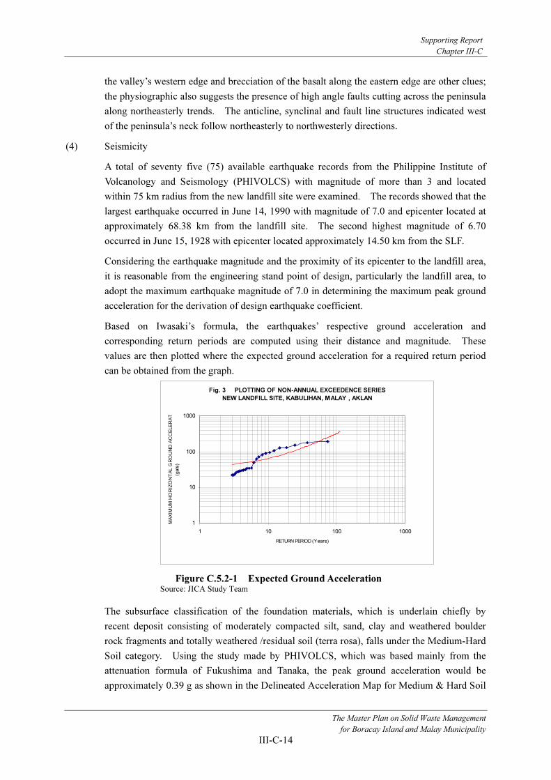
Based on Iwasaki’s formula, the earthquakes’ respective ground acceleration and
corresponding return periods are computed using their distance and magnitude. These
values are then plotted where the expected ground acceleration for a required return period
can be obtained from the graph.
Fig. 3 PLOTTING OF NON-ANNUAL EXCEEDENCE SERIES
NEW LANDFILL SITE, KABULIHAN, MALAY , AKLAN
1
10
100
1000
1 10 100 1000
RETURN PERIOD (Years)
MA
XIM
UM
HO
RIZ
ON
TA
L G
RO
UN
D A
CC
ELE
RA
T
(ga
ls)
Figure C.5.2-1 Expected Ground Acceleration Source: JICA Study Team
The subsurface classification of the foundation materials, which is underlain chiefly by
recent deposit consisting of moderately compacted silt, sand, clay and weathered boulder
rock fragments and totally weathered /residual soil (terra rosa), falls under the Medium-Hard
Soil category. Using the study made by PHIVOLCS, which was based mainly from the
attenuation formula of Fukushima and Tanaka, the peak ground acceleration would be
approximately 0.39 g as shown in the Delineated Acceleration Map for Medium & Hard Soil

Supporting Report
Chapter III-C
The Master Plan on Solid Waste Management
for Boracay Island and Malay Municipality
III-C-15
(Figures C.5.2-2, 3 and 4). The derived g value (0.204 g) is comparatively lower than the g
value obtained from the abovementioned figures.
Figure C.5.2-2 g Factor Contour Map for Rock
Figure C.5.2-3 g Factor contour Map for Hard Soil
Figure C.5.2-4 g Factor Contour Map for Medium Soil
Source: PHIVOLCS
(5) Seismic Related Hazard
Seismic hazard is the risk of injury or death to man and damage or destruction of engineering
structures by ground motions caused by faulting and earthquakes. Infrastructure facilities
and the environment can be affected by an earthquake. The degree of impact on structures
depends upon such factors as the magnitude and characteristics of the tremor, the response

Supporting Report
Chapter III-C
The Master Plan on Solid Waste Management
for Boracay Island and Malay Municipality
III-C-16
characteristics of the geologic units upon which the facility is situated and of the facility
itself, and the proximity of the facility to the energy source (seismic generator). The
damage is caused by shaking and ground rupture generated by an earthquake. Some of this
damage such as landslides, floods, liquefaction, etc. could result in numerous other types of
hazards.
In the landfill site, the only identified seismic related hazard so far is slope failure. The
factors causing the failure are related to the physical properties of the slope material and the
subsequent history of crustal movements, erosion and weathering processes. Some of these
factors are removal of lateral support, surcharge, transitory earth stresses, removal of
underlying support, inherently weak material, orientation of the slope, amount of weathering,
and changes in inter-granular forces, e.g. seepage force. Topography and drainage likewise
play an important role.
Increase in seepage force or pore water pressure build-up within the slope during heavy rains
through percolation or infiltration in addition to the orientation of the toe of the slope caused
by the cut slope and the nature & condition of the soil are the factors that causes the slope
failure.
(6) Geologic Condition
The sanitary landfill area is blanketed of considerably thick colluvial deposit (gravelly clay,
sandy silt, silty sand & bouldery clay/sand/silt). Underlain by a thick totally
weathered/residual soil (terra rosa) as indicative of moderately to strong tropical weathering
from Sta. Cruz and Fragante formation (Interbeds of basalt flows, shale, siltstone, mudstone
and conglomerate). Massive basalt outcrops are generally exposed along creek/river shoals.
This rock unit of Fragante Formation is generally very dark gray color and with distinct
volcanic flow bedding in places, trending to N 50-100 E and dipping from 40 to 60 degrees
to the Northwest. Bed spacing is measured from 10 cm to 30 cm. Partings between beds
of the rock unit were noted to be open and interconnected making this rock unit as pervious
and relatively high percolation rate. Several joint sets, shears and fractures were measured
as follows:
J-1 Strike-approximately N 600 W & dip-approximately 40
0 NE
J-2 Strike-approximately N S & dip-approximately 350 E
J-3 Strike-approximately EW & dip-approximately 650 N
J-4 Strike-approximately N 100 E & dip-approximately 40
0 NW
J-5 Strike-approximately N 300 E & dip-approximately 30
0 SE
J-6 Strike-approximately N 100 W & dip-approximately 70
0 NE
J-7 Strike-approximately N 100 W & dip-approximately 50
0 NE
J-8 Strike-approximately N 400 E & dip-approximately 60
0 NW
J-9 Strike-approximately N 200 W & dip-approximately 60
0 NE
Most of the joints and shears are steeply dipping (400-70
0) to vertical with dips mostly
towards to the east or it is related to the high angle fold plunging to the east.

Supporting Report
Chapter III-C
The Master Plan on Solid Waste Management
for Boracay Island and Malay Municipality
III-C-17
(7) Slope Stability
Based from the surface mapping and laboratory tests on the landfill area soil cover; the
relationship between friction angle and cohesive strengths and stability of slopes of various
materials were established as follows:
- Slope Height: 4-8 meters
- Slope Face Angle: 60-80 °
- Estimated Cohesion: 21.5 kPa
- Estimated Friction Angle: 19°
- Typical unit Weight of soil covering: 17 kN/m3
- Unit Weight of Water: 9.8 kN/m3
- Computed Horizontal Acceleration: 0.204 g
Since some of the Slopes section is already cut, factor of safety is definitely less than 1.
Imminent slope failure is noted on the access road cut due to steepness of the existing slope
angle.
(8) Hydro-geological Condition
Surface mapping and reconnaissance along the immediate vicinity of the new landfill site
indicates that the area is widely underlain by fractured basalt (Fragante Formation) where
groundwater within the rock unit is relatively developed. Under these condition, highly
fractured basalt yields from less than 15 to 36 liters/minute and permeability (K) values is
in the order of 10-5 m/sec (BMG , R.I. No. 100), February 1980. Unfortunately, based from
the core drilling investigation only an upper (fractured) proportion of the underlying basalt
(7-12m) of this resource will be an aquifer. The underlying layer is fresh and massive
basalt which is non-bearing aquifer. During rainy season, surface run off along natural
water ways is very high due to relatively low percolation rate of the thick overburden
materials (silty clay, gravelly silt, clayey silt & bouldery/gravelly clay).
The presence of a highly pervious overburden material (silty sand/sandy silt) in the slope
mass will increase the influx of surface and subsurface water toward the slope face. This
could cause the build-up of a considerable hydrostatic head and would act as a driving force
of considerable magnitude to trigger slope failures during rainy season. Poor drainage on
the slope will further destabilize the slope mass by increasing seepage force.
The interface between the thick overburden and the highly/closely fractured basalt rock unit
of the fragante formation is the probable aquifer within the area of study. The massive
basalt underlying the highly fractured basalt is impermeable enough with approximate
permeability of not greater than 10-5
m/sec to prevent any downward migration or vertical
leakage of groundwater, at this depth the permeability diminish due to wide tight
fractures/joints and the absence of significant geologic structures (sheared & fault zone)
which serves as the migration path of groundwater.
Groundwater recharge depend on the amount of rainfall, data of evapo-transpiration and on
the catchments/drainage area. Recharge rate is moderate to high due to the highly fractured
basalt and loose colluvial /residual soil deposit.

Supporting Report
Chapter III-C
The Master Plan on Solid Waste Management
for Boracay Island and Malay Municipality
III-C-18
5.2.2 Field Survey, Sampling and Laboratory Analysis
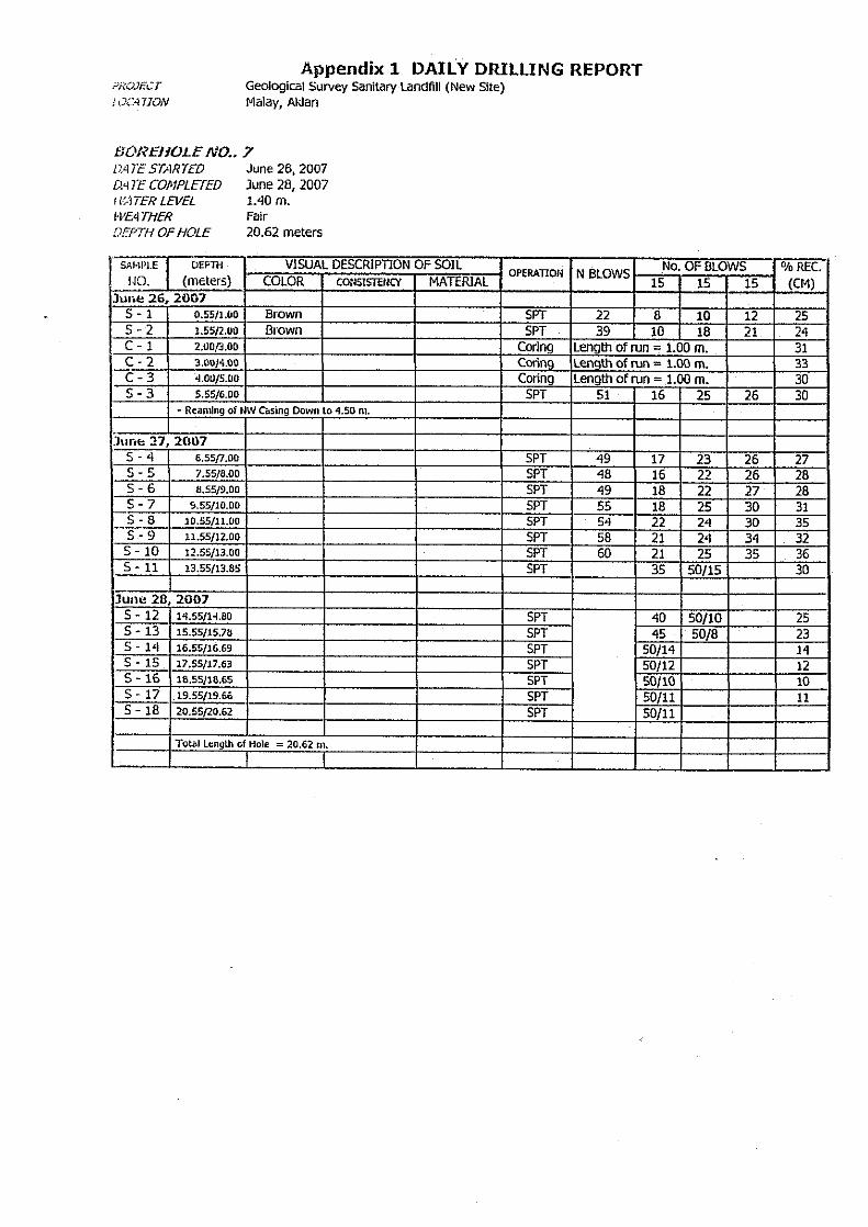
(1) Core Drilling exploration
Subsurface exploration by core drilling was undertaken to determine the engineering
properties of overburden materials. A total of eight bore holes with an aggregate depth of
160.39 meters and four observation wells with a total depth of 80 meters was drilled .Table
5.2-2 shows the summary of the boreholes drilled, depth and elevation. A location map is
also presented showing the boreholes drilled at the new landfill area.
Table C.5.2-2 Summary of Boreholes Drilled
Borehole Number Total Depth Drilled (M) Elevation ( M)
BH-1 20.10 138.17
BH-2 20.04 138.40
BH-3 20.08 112
BH-4 20.13 127.21
BH-5 20.09 102
BH-6 19.65 108.77
BH-7 20.62 121
BH-8 19.68 147.24
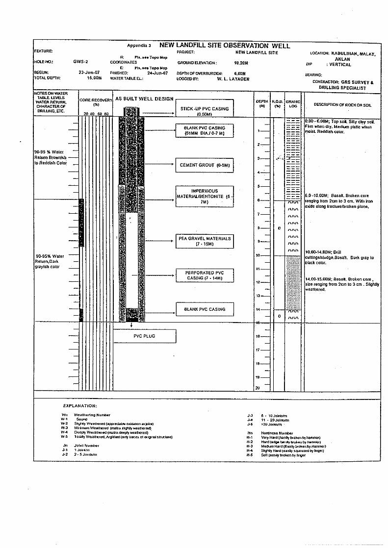
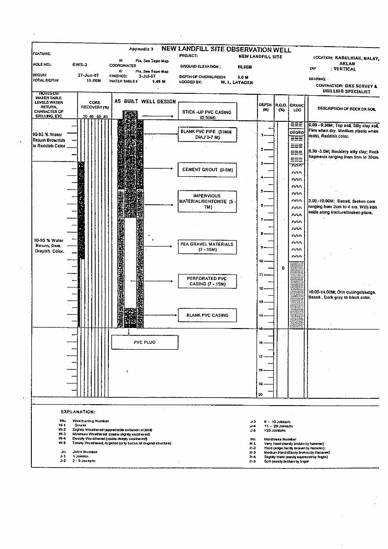
GWD-1 25.00 89.47
GWS-2 15.00 90.20
GWS-3 15.00 86
GWD-4 25.00 86.20
Source: JICA Study Team
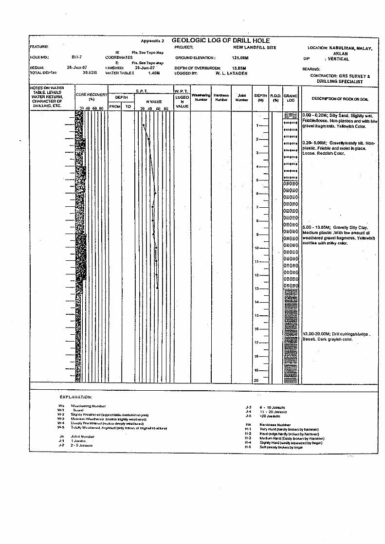
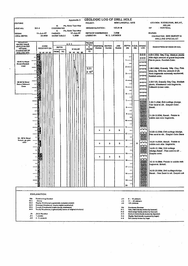
(2) Geologic Logs of Drill Holes
BH-1, which is located at the central upper slope of the landfill area drill to the depth of
20.10 meters from the ground surface. Eight (8) meters from the surface is made of
alternating layers of silty sand, gravelly sandy silt and mixture of unconsolidated gravel,
pebble, sand and silt. The underlying moderate to extremely weathered bedrock is alternating
layers of basalt flows, shale, mudstone, siltstone and conglomerate (Fragante Formation).
Core recovery of this borehole ranges from 7% to 28% indicating very poor rock quality
designation.
The borehole drilled at the temporary dumpsite area, BH-2 (20.04m), encountered a nine (9)
meters thick gravelly clay materials and underlain the same bedrocks (Fragante Formation).
Core recovery ranges from 4% to 28%.
Borehole BH-3 (20.08M depth), which is located mid-right portion of the landfill area,
penetrated through a fifteen (15) meters thick overburden materials composed essentially of
layers of reddish silt clay and silty sand that are dense to very dense.
Borehole BH-4 (20.13M depth) was drilled at the mid-right portion of the landfill area
encountered the same bedrock after seven (7) meters thick of reddish layers of silty clay and
gravelly silty clay. The underlying bedrock is poor rock quality as depth increase poor core
recovery is noted.

Supporting Report
Chapter III-C
The Master Plan on Solid Waste Management
for Boracay Island and Malay Municipality
III-C-19
Borehole BH-5 (20.09M depth) is located at the northeastern portion of the new landfill area.
The thickness of layers of gravelly silty clay and fat clay is about 18.65M. Poor core
recovery ranges from 9% to 33 %.
Borehole BH-6 (19.65M depth) was drilled at the midsection of the landfill area. It is made
of layers of silty/ clay gravel, silty clay and totally weathered bedrock. Poor core recovery
ranges from 8% to 28%.
Borehole BH-7 (20.62M depth) is located upper midsection of the landfill area. The
thickness of overburden is 13 meters. It is made of medium dense to very dense layers of
silty sand, gravelly sandy silt, and gravelly silty clay.
Borehole BH-8 (19.68M depth) is located at the southwestern upper most section of the
landfill area. It is made of medium dense to very dense layers of gravelly silty clay,
gravelly/ clayey silt and silty/clayey gravel.
Boreholes GWD-1, GWS-2, GWS-3 and GWD-4 are located at the foot slope of the landfill
area. It is covered with silty clay soil. It is underlain by basalt flow (Fragante Formation).
The bed rock is closely fractured/jointed, and slight to moderately weathered.
(3) Standard Penetration Test Results
The SPT was conducted to determine the overburden bearing capacity/strength based from
resulting N-values. The SPT results of all the boreholes conducted are shown in Table
C.5.2-3. The SPT data reveals that there is an increase in bearing strength of the soil and
deeply weathered rock in deeper portions. The overburden soils encountered across the site
is made generally of reddish to yellowish gravelly silty and clayey silt of medium plasticity,
and silty sand of very low to no plasticity. The bedrock encountered is slightly weathered
and strong as noted in boreholes (GWD-1, GWS-2, GWS-3 &GWD-4) located near the
lower most part of creek lines traversing the landfill area.
Based on the SPT results, the foundation materials at landfill area is covered with layers of
medium dense residual and colluvial soils (22-26 N-value), and underlain with gradually
grading to higher density overburden materials. The layers of moderately compacted
overburden are dense (31-50 N-Value). The highly compacted overburden materials
produced high SPT blow counts (>51 N-value), revealing an increase in compaction,
consolidation and higher quantity of granural/or gravel fragments.
The typical soil and mechanical properties of strata estimated from the N-Value (SPT)
undertaken from cohesive, non-cohesive and extremely to totally weathered intercalating
basalt flow, shale, mudstone, siltstone and conglomerate are enumerated below.

Supporting Report
Chapter III-C
The Master Plan on Solid Waste Management
for Boracay Island and Malay Municipality
III-C-20
Table C.5.2-3 Soil Mechanical Properties
Typical Range of Unit Weight ,KN/M3 Borehole
No. Depth (M) SPT (N) Value
Relative Density , %
Moist Submerged
Typical Ultimate Bearing Capacity (qu)=kg/cm2
0.55-1.00 39 65-85 18.3-22.0 10.2-13.4 >4 BH-1 1.55 –
14.12 59 to
refusal 85+ 20.4-23.6 11.8 >4
0.55 – 1.0 24 35-65 17.3-20.4 9.4-11 2 - 4 1.55 – 3.0 42 -46 65-85 18.3-22.0 10.2-13.4 >4 3.55-4.0 51 85+ 20.4-23.6 11.8 >4 4.55-7.0 47-48 65-85 18.3-22.0 10.2-13.4 >4
BH-2
8.0-9.10 refusal 85+ 20.4-23.6 11.8 >4 0.55-3.0 35-38 65-85 18.3-22.0 10.2-13.4 >4 3.55-6.0 41-47 65-85 18.3-22.0 10.2-13.4 >4 BH-3
6.55-18.17 54 to refusal 85+ 20.4-23.6 11.8 >4
0.55-2.0 40-42 65-85 18.3-22.0 10.2-13.4 >4 BH-4
3.55-9.13 56 to refusal 85+ 20.4-23.6 11.8 >4
0.55-2.0 40-44 65-85 18.3-22.0 10.2-13.4 >4 BH-5 2.55
-17.70 51 to
refusal 85+ 20.4-23.6 11.8 >4
0.55-5.0 31-39 65-85 18.3-22.0 10.2-13.4 >4 BH-6 5.55
-15.79 52 to
refusal 85+ 20.4-23.6 11.8 >4
0.55-2.0 22-39 35-65 17.3-20.4 9.4-11 >4 BH-7 5.55-6.0 51 85+ 20.4-23.6 11.8 >4 6.55-9.0 48-49 65-85 18.3-22.0 10.2-13.4 >4
BH-7 9.55-15.78 54 to
refusal 85+ 20.4-23.6 11.8 >4
0.55-2.0 21-26 35-65 17.3-20.4 9.4-11 2-4 2.55-7.0 32-44 65-85 18.3-22.0 10.2-13.4 >4 BH-8
7.55-10.0 55-63 85+ 20.4-23.6 11.8 >4
Source: JICA Study Team
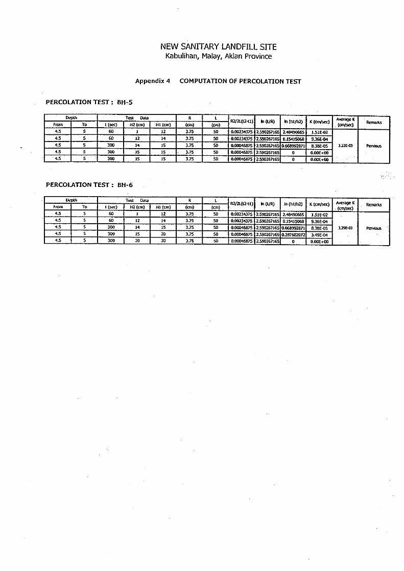
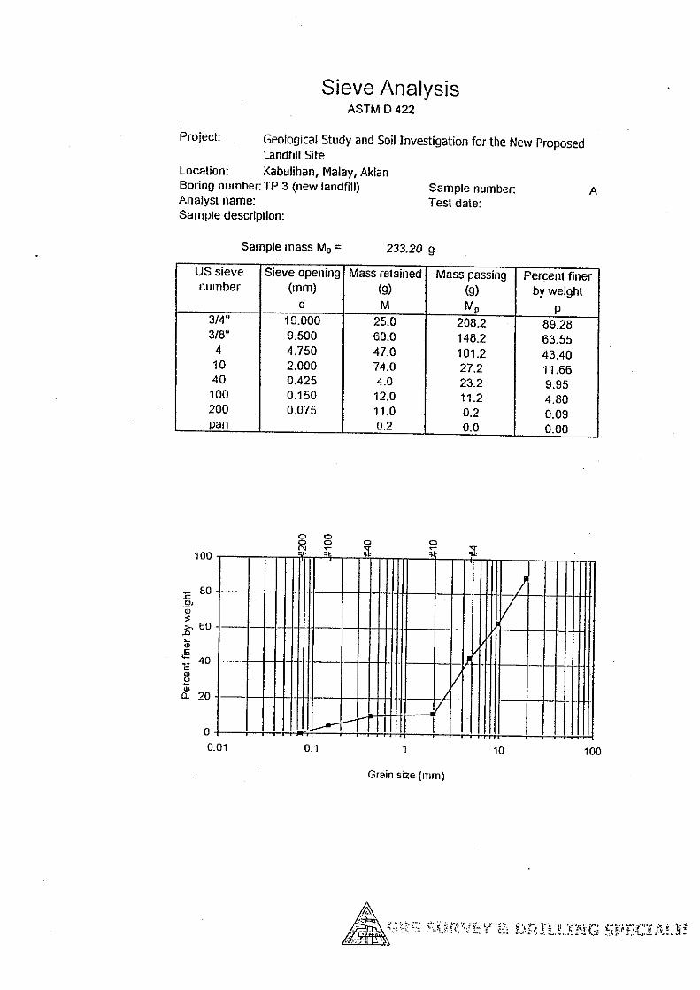
(4) Permeability Test Results
A total of seven (7) settings consisting of four (4) percolation tests (PT) and three (3) water
pressure tests (WPT) were conducted on the drill holes. Table C.5.2-4 below is the
summary of the field permeability test results obtained from the boreholes.
Table C.5.2-4 Summary of Permeability Test Results
Borehole N0. Type of Field Test
Test Section (M)
Average K (CM/SEC) Remarks
BH-2 PT 6.3 - 7 7.74 X 10 -4 Pervious BH-3 PT 3 - 4 5.70 X 10⁻⁵ Semi-pervious BH-4 PT 2 - 3 5.51 X 10⁻⁴ Pervious BH-5 PT 4.5 - 5 8.38 X 10⁻⁵ Semi-pervious
GWD-1 WPT 7 - 12 1.28 X 10⁻⁴ Pervious GWD-1 WPT 13 - 18 4.39 X 10⁻⁵ Semi-pervious GWS-2 WPT 7.50 – 15 2.6 X 10⁻⁴ Pervious
Source: JICA Study Team

Supporting Report
Chapter III-C
The Master Plan on Solid Waste Management
for Boracay Island and Malay Municipality
III-C-21
The field permeability test results of the drill holes revealed that the overburden materials
encountered ranged from pervious to impervious condition.
(5) Infiltration Test Result
Result of four (4) infiltration tests is presented in Table C.5.2-5. Average infiltration rates
obtained at different soil texture varied from 5.35 centimeters to 17.65 centimeters per hour.
In terms of basic infiltration, the rates varied from 3.21 cm to 10.24 cm per hour. The mean
average of 11.95 and 6.83 cm per hour for average and basic infiltration, respectively, show a
rapid values. These rapid intake rates suggest that the landfill area soil covering is granular
and very pervious.
Table C.5.2-5 Result of Field Infiltration Test
Infiltration Rate Test Site No. Location Surface Soil Type
Basic Average Class
1 Kabulihan, Malay Gravelly/sandy silt/silty sand 3.21 5.35 Moderate2 Kabulihan, Malay Gravelly/sandy silt/silty sand 10.24 17.65 Rapid 3 Kabulihan, Malay Gravelly/sandy silt/silty sand 6.84 12.66 Rapid 4 Kabulihan, Malay Gravelly/sandy silt/silty sand 7.03 12 Rapid
Source: JICA Study Team
(6) Test Pitting
The main source of construction materials for the clay liner may be quarried at the landfill
area and vicinity. A total of six (6) test pits have been dug at the site with a maximum depth
of three (3) meters after stripping of unfavorable soil covering. Bulk samples were taken
for laboratory analysis.
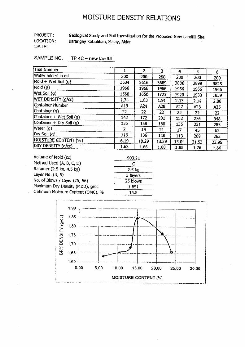
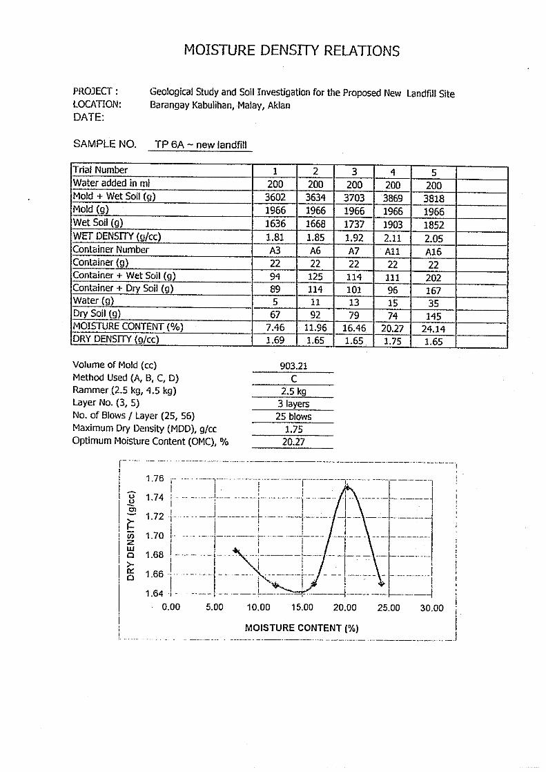
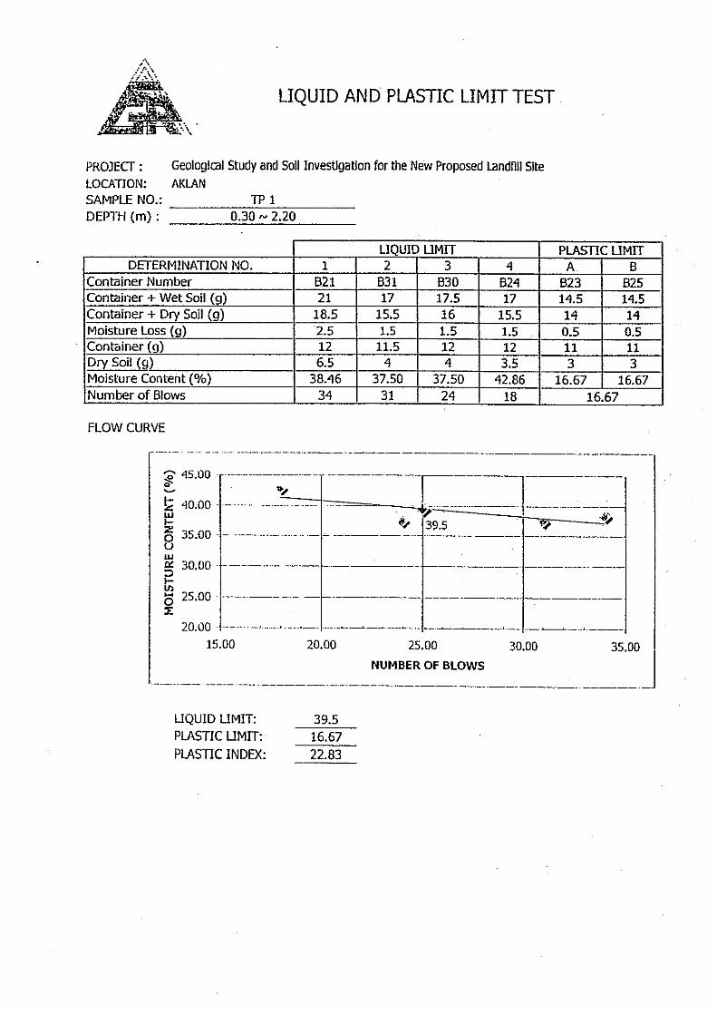
(7) Laboratory Test Result
Laboratory test results indicates that the physical properties of the soil such as natural
moisture content (NMC) have values that ranges from 11.23 % to 28 % and the optimum
moisture content (OMC) have values ranging from 15.5% to 20.27%. Such materials
belong to the ML-SM group of soils characterized by low plasticity and compressibility.
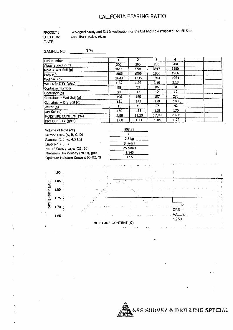
Mechanical properties of the soil by California Bearing Ratio (CBR) test was conducted on
the soil samples (TP-3 &TP-1). Values obtained for the Maximum Dry Density and Optimum
Moisture Content is as follows :
Maximum Dry Density, MDD (g/cc) 1.74 to 1.85
Optimum Moisture Content, OMC (%) 15.5 to 20.27
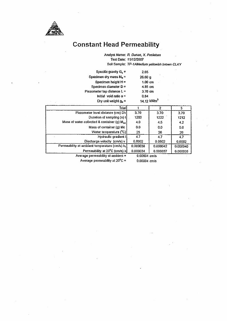
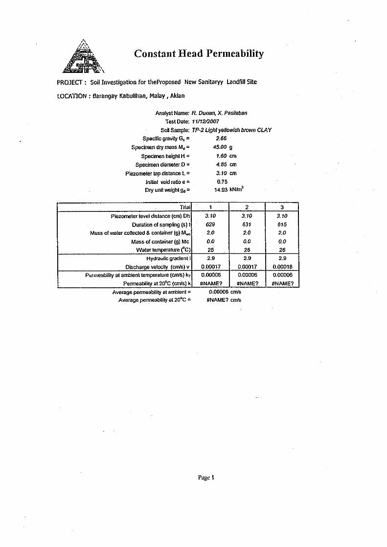
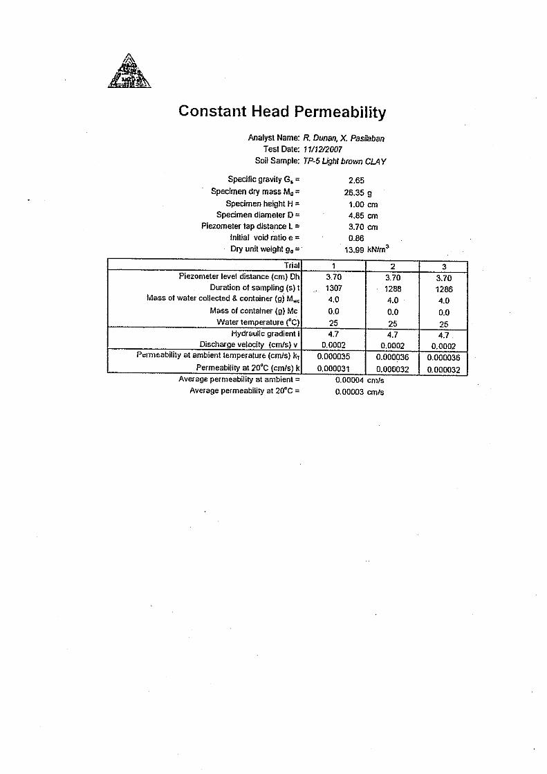
Permeability tests conducted on three (3) samples used for the compaction tests resulted on
coefficients of permeability (K ave.) within 10-5 to 10
-6 cm/sec. indicating that the soils are
practically semi-pervious to impervious when properly compacted.

Supporting Report
Chapter III-C
The Master Plan on Solid Waste Management
for Boracay Island and Malay Municipality
III-C-22
(8) Groundwater Monitoring Wells
Four (4) ground monitoring wells were constructed at the foot slope of the landfill area.
The area is covered about one (1) meter to 6.80 meters silty clay soil and underlain by
closely fractured/jointed basalt. The rock is moderate to slightly weathered, hard and dense.
The ground water level is ranging from 10.75m to 11.70m for GWD-1 & GWS-2 and 1.46m
to 1.95m for GWS-3 & GWD-4respectively. The depths of ground water elevation of the
boreholes are controlled by recharge source (creek /gulley/river) of the area.
5.2.3 Conclusion
Surface geo-mapping conducted at the landfill area reveals that alternating layers of fine soils
(silty clay, clayey silt & gravelly silty clay), granular materials (silty sand, sandy silt, &
gravel/sand/silt/pebble) and basalt flow favors the soundness of new landfill site. The
alternating layers measured 250 to 70
0 dip against the slope face. In particular; silty clay,
gravelly silty clay, clayey silt & basalt flow serves as impervious membrane that control the
inflow of leachate into the groundwater table. Results of surface and geohazard mapping
indicate that the slope surrounding the landfill area can undergo localized slope failure
during intense rainfall of long duration since some portion of the upper layer soil is
loose/unconsolidated.
The stability of the slope depends upon the future surcharge at the landfill area and vicinity.
In addition, poor drainage conditions resulting to reduction in the shear strength of the slope
mass and will lower the factor of safety of the slope.
The landfill area experienced earthquakes for every 11 to 22 years return period with
magnitude ranging from 6.1 to 7.0 since it is located at considerable distance from the Tablas
Fault. A properly designed landfill area has no risk in the considerably high ground
acceleration.
Seismic analysis is an important factor that must be considered for the design of a sanitary
landfill. The design earthquake coefficient is very crucial and should be derived based on
delineated acceleration maps in soft soil, medium soil, hard soil and rock. Seismic induced
hazards should likewise be anticipated and studied in order to protect the soundness of the
proposed sanitary landfill project.
The subsurface investigation conducted indicated that the thickness of overburden materials
at the landfill area ranges from 1.0 meter to more than 20 meters thick as shown in the
lithologic logs. The colluvial deposit and residual soil of Sta. Cruz and Fragante
Formations are regarded as overburden. The impression is that there are two (2) layers of
overburden materials deposited in different geologic time. Only the older or deep-seated
residual deposit is well-compacted/consolidated, that is in places overlain by the newly
deposited or loose younger colluvial materials. However, field tests conducted yielded
N-value ranging from 21 to >50 giving a medium dense to very dense nature and condition
of the overburden materials.

Supporting Report
Chapter III-C
The Master Plan on Solid Waste Management
for Boracay Island and Malay Municipality
III-C-23
The percolation test results revealed that the foundation material is highly pervious (10-4
cm/sec) wherein water infiltration is high causing pore water pressure build-up that
eventually reduces the degree of consolidation/or compaction of the overburden materials.
The very pervious colluvial / old landslide deposit (foundation materials) in the landfill area
can act as passageway of surface run-off. This can facilitate the infiltration of groundwater
or rain water and thus result to slope failure. This was observed from the slopes located
along the national highway connecting the town of Malay and Buruanga which shows
progressive circular slope failure caused by underlying poorly unconsolidated materials and
poor drainage condition.
The test pits and laboratory tests conducted indicated that the overburden materials are made
of alternating layers of fine and granular soil. Selective mining is necessary to extract
suitable materials for the clay lining of the landfill area.
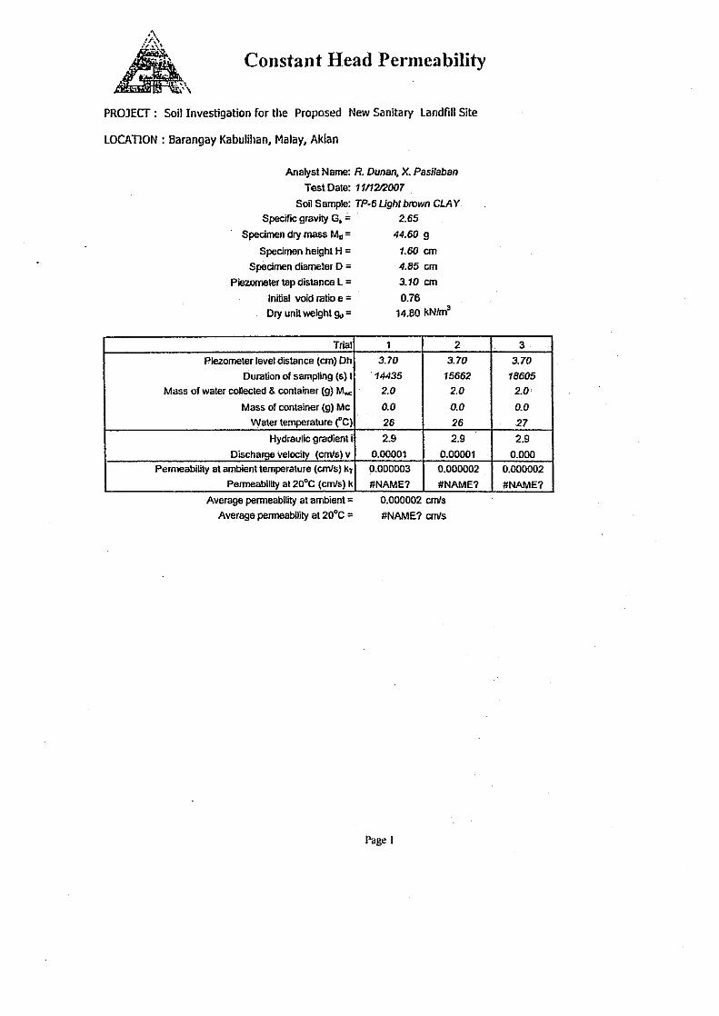
Constant Head Permeability Test (CHPT) on remolded soil samples reveals that permeability
(10-6
cm/sec) improves when it is properly compacted particularly in TP-6 soil samples of
which made of gravelly silty clay and silty clay. The type of material is suitable for clay
lining of the landfill area.
5.3 Environmental Survey
5.3.1 Water Environment
(1) Surface Water
Surface water samples collected in three monitoring station was brought to F.A.S.T
laboratory for analysis. The result shows the following areas of concerns:
- High concentration of total coliform in all sampling locations including groundwater
wells
- Presence of dursban and diazinon, normally found in insecticides and pesticides in a
groundwater well used by the communities in Barangay Kabulihan
(2) Groundwater
The groundwater within the landfill site has been given focus since it is vulnerable to
contamination from the solid waste. Four were selected as groundwater sampling sites.
(3) Aquatic Flora and Fauna
Another important ecosystem that is a direct receptor of the impact of the new landfill site is
the riverine ecosystem of the Malay River. These riverine organisms include: fishes, shells,
mollusks and crustaceans. The residents of Kabulihan catch these organisms mainly for
their daily consumption and not for any economic gain like selling. Catching is done
almost everyday as the Malay River serves the residents multiple purpose like bathing, doing
their laundry and getting their domestic water. There is some information of riverine fish in
down steam of new proposed SLF as well as the stretch of the Malay River and its
turbutaries.

Supporting Report
Chapter III-C
The Master Plan on Solid Waste Management
for Boracay Island and Malay Municipality
III-C-24
Some of the fishes such as goat fish or Philippine butterfly fish caught as well as mollusk
such as snails, clams scallops and oysters of are in enumerated. Fishing is done in the deep
seas of Pandan Bay or even Sulu Sea. A small percentage of the respondents are engaged in
fishing as a source of income. In addition, corals are the most common type of
coelenterates on Boracay Island and other reef on the Mainland of Malay. The
hydrocorals-stony or hard corals come in various colors, shapes, sizes and forms.
5.3.2 Air Environment
(1) Landfill Gas
The geographical extent of air quality resistance has been considered up to 3 km radius from
the project site. The landfill gas was recorded and shown in Table C.5.3-1.
Table C.5.3-1 Results of the Gas Sampling for Methane (CH4), Carbon Dioxide (CO2),
Hydrogen Sulfide (H2S), Ammonia (NH3)
Station Location Time Instrument Used Result 1 Guard House 1:00 pm G450 Portable Gas Below detection limit 2 N 11°52.257’
E121°54.360’ 1:35 pm G450 Portable Gas Below detection limit
3 N 11°52.305’ E121°54.405’ 1:55 pm G450 Portable Gas Below detection limit
4 N 11°52.323’ E121°54.414’ 2:15 pm G450 Portable Gas Below detection limit
5 N 11°52.331’ E121°54.443’ 2:35 pm G450 Portable Gas Below detection limit
Source: JICA Study Team
1) Methane (CH4)
Methane is non toxic, however, it is highly flammable and may form explosive mixture with
air. It is violently reactive with oxidizer, halogen and some halogen-containing compound.
Methane is also asphyxiant and may displace oxygen in an enclosed spaced. Asphyxia may
result if the oxygen concentration is reduced to below 19.5% by displacement. The CH4
was not detected during surface sampling.
2) Carbon Dioxide (CO2)
Carbon Dioxide (CO2)is a chemical compound composed of low oxygen atoms covalently
bonded to a single carbon atom. It is a gas at standard temperature and pressure and exists
in earth’s atmosphere as a gas. It is a colorless odorless gas. When inhaled at higher
concentration than usual atmospheric levels. It can produce a sour taste in the mouth and a
stinging sensation in the nose and throat. At standard temperature and pressure, the density
of carbon dioxide is around 1.98 kg/m3, about 1.5 times that of air. The CO2 level was not
detected on the period of measurement.
3) Hydrogen Sulfide (H2S)
Hydrogen Sulfide (H2S) is a colorless gas that smells like a rotten eggs (from the Sulphur).
Often referred to as “sewer gas” and is highly poisonous. Usually the poisoning caused by

Supporting Report
Chapter III-C
The Master Plan on Solid Waste Management
for Boracay Island and Malay Municipality
III-C-25
hydrogen sulfide is through inhalation and has toxicity similar to cyanide. It is found in
petroleum and natural gas and sometimes present in ground water. The results shown in
Table C.5.3-2 from the different observation point during surface gas sampling, shows that
H2S is not detectable
4) Ammonia (NH3)
It is normally encountered as a gas with a characteristics pungent odor. Although ammonia
contributes significantly to the nutritional needs of earth, the gas itself is caustic and cause
serious health damage.
Based on the results of the air sampling, the air quality within the proposed landfill and
within the direct impact area is not detectable for gas emissions.
(2) Noise Level
The noise level was recorded and shown in Table C.5.3-2. The sounds recorded under
normal condition is 40-60 dB(A). Normally the sound generated under normal condition
was produced by wind blowing, animal sound, birds singing and workers in the site. The
Maximum recorded sound was 60 dB (A).
Table C.5.3-2 Results of the Noise Level Measurement on July 29, 2007
Station GPS Location Time Method/Instrument Used
Level (dBA) Activities
1 N 11°52.257’ E121°54.360’ 1:35 pm
Portable Sound Meter
40-50 Normal condition, sound produce by air and 2-3 workers in the site.
2 N 11°52.305’ E121°54.405’ 1:55 pm Portable Sound
Meter 50-60 Sound produce by air and
4-5 workers in the site. 3 N 11°52.323’
E121°54.414’ 2:15 pmPortable Sound Meter
50-60 Sound produce by air, 2-3 workers in the site cutting wood and birds singing.
4 N 11°52.331’ E121°54.443’ 2:35 pm
Portable Sound Meter
50-60 Sound produce by air, 2 workers in the site, birds singing and water flowing.
Source: JICA Study Team
According to the rules and regulations of the National Pollution Control Commission of the
Philippines (NPCC), noise standards are set for four different categories, namely i) general
areas, ii) areas directly fronting/facing 4- lane road, iii) areas directly fronting/facing 4-lane
or wider road, and iv) for construction activities. These are shown in Table C.5.3-3.

Supporting Report
Chapter III-C
The Master Plan on Solid Waste Management
for Boracay Island and Malay Municipality
III-C-26
Table C.5.3-3 Noise Standards in General Areas (dB)
Category of Area Daytime Morning & Evening Nighttime AA 50 45 40 A 55 50 45 B 65 60 55 C 70 65 60 D 75 70 65
Note:
AA – a section or contiguous areas which requires quietness, such as an area within 100 meters from
school sites, nursery schools, hospitals and special homes for the aged.
A – a section or contiguous area which is primarily used for residential purposes.
B – a section or contiguous area which primarily a commercial area.
C – a section primarily reserved as a light industrial area, and
D – a section which is primarily reserved as a heavy industrial area.
– Daytime - 9:00 a.m. to 6:00 p.m.
– Morning - 5:00 a.m. to 9:00 p.m.
– Evening - 6:00 a.m. to 10:00 p.m.
– Nighttime - 10:00 a.m. to 5:00 p.m.
Source: NPCC
On the other hand, the maximum noise standards for construction activities and allowable
working hours are show in Table C.5.3-4.
Table C.5.3-4 Maximum Noise Standards for Construction Activities and Allowable Working
Hours Per Area
Class of Activity Maximum Noise Level Allowable Working Hours Areas
Class 1 90 dB (A) 7:00 a.m. – 7:00 p.m. AA,A,B
Class 2 85 dB (B) 7:00 a.m. – 7:00 p.m. AA,A,B
Class 3-4 75 dB (C) 7:00 a.m. – 9:00 p.m. AA,A,B
Source: NPCC
(3) Odor
In the site, odor is identified to be the location of the odor description and was conducted last
July 28, 2007 at about 1-3 pm. Generally, the odor depends on the location of the receptor
and it was concluded that no foul odor was experience in the proposed SLF only presence of
abundant flies.
5.3.3 Flora
Barangay Kabulihan still is home to a great number of plant species which are endemic in
the area. During the transect walk conducted, 60 plant varieties were identified used mainly
as food, medicine, lumber and fuel by the residents. There was one introduced specie,
mahogany which was seen during the transect walk, cultivated on a backyard. Endemicity
of the plants is very prevalent within every 3-5 meters walk along the terrain of the Malay
watershed.
(1) Fruit bats
Fruit bats are commonly observed in the area according to Barangay Kagawad Ms. Adelfa
Tumaob, and Mr. Roberto Gulay, two of the KIs in the new landfill site. This claim has
been supported by the local residents in the natural survey. These bats are sighted at Mt.

Supporting Report
Chapter III-C
The Master Plan on Solid Waste Management
for Boracay Island and Malay Municipality
III-C-27
Luho especially in the afternoons. It is a large fruit-eating bat species of the family of
Pteropodidae. These species preferred fruits of Bulabog (Parishia maingayi) and Bogo
(Garuga floribunda) and as roosting trees in the area. Several species of fruit bats are found
on the Mainland of Malay, but only two species are found to roost on Boracay Island namely
Acerodon jubatus and Pteropus vampyrus which have been listed as endangered and
vulnerable, respectively1. Acerodon jubatus is commonly known as the Golden-capped
fruit bat and locally known as Kabog. These species is similar with Pteropus vampyrus in
size, external appearance and habits. The color varies a great deal especially on the extent of
the yellow or buff and orange-buff patch on crown and back of neck and upper back. The
Pteropus vampyrus is commonly known as Red-necked flying fox and locally known as
Kabog to residents. It is a large bat with long ears which is pointed at the tip. The body
covered with fur at different degree of thickness. Generally, the color is blackish brown
with head, neck and mantle as black while the shoulder, neck and rump are colored
rufous-brown. Its definite roosts are often found in some particular clump of trees where
they usually stay until driven away by necessary disturbance. Both species produce a very
strong peculiar musky odor characteristics of their roosting area and very different from the
urine stench of other animals.
Indiscriminate habitat destruction and hunting activities by residents are the two most
common factors endangering fruit bats. Most people are not aware about the critical status
of fruit bats nor they know how important fruit bats are to the forest.
(2) Monkeys (Cercopithecidae)
Monkey (Macaca fascicularis) - Unggoy, amo, in the area is commonly associated with many
fallen young coconut fruits. Key informants stated that monkeys are often cited in the
forested areas of the site and even on their yards and in the dumpsite. Some have even visited
the “drilling group” of the study team. There are around 10-20 heads that are roaming
around the areas. The members include both sexes and of all ages, headed by huge old
male. Sometimes monkeys are captured for food and sometimes sold as pets. Some riverine
organism and insects in the area were also discovered during the transect walk.
(3) Reptiles
There are several species of reptiles, the most dominant terrestrial herpetofaunal species in
the area are the Malay Monitor Lizard (Varanus salvator of the family Pythonidae) and
Python (Python reticulatus the family Pythonidae). These reptiles are carnivores and feed
on small live animals. In the case of Python, they are so adaptable that they can even
occasionally seek dwelling in human shelter. In addition, Python reticulatus is a natural
predator for rats.
1 International Union for the Conservation of Nature, 2002

Supporting Report
Chapter III-C
The Master Plan on Solid Waste Management
for Boracay Island and Malay Municipality
III-C-28
5.4 Human Environment
5.4.1 General Information (Health Information)
Even before the operation of the SLF in the Kabulihan, respiratory diseases like pneumonia
tuberculosis in on the top 5 of the leading causes of mortality in Malay. There are several
medical facilities that caters to the people: a private hospital in Barangay Caticlan, a
municipal hospital in Barangay Motag, a municipal health office (MHO) in Barangay
Poblacion,an Emergency Hospital on Boracay Island and six (6) Barangay Health Stations.
5.4.2 Survey Area
Barangay Kabulihan, the location of the proposed SLF is one of the nine (9) Barangays
covered by Malay Municipality. It is composed of seven (7) Sitios2: 1- Sitio Maliyong, 2-
Sitio Proper, 3- Sitio Lingo, 4- Sition Minorok, 5- Sitio Agnaga, 6- Sitio Bajangan, and 7-
Sitio Bulutinao. The SLF is presently located in Sitio Bulotinao and very near or nearly
adjacent to another Malay barangays, Barangay Dumlog and Barangay, Buruanga
Municipality. During the period of the survey in July-August 2007, Barangay Kabulihan
has a total population of 500 and 115 households.
(1) Social Services
Kabulihan is accessible from the Poblacion via aconcrete national highway using a public
transportation system the tricycle. A barangay feeder road and several bamboo foot bridges
link the residents of the different sitios to the barangays proper. The Barangay is being
served by an elementary school, a day care and a Roman Catholic Chapel. A basket ball
court doubles a solar dryer for the residents
(2) Infrastructure Services
Aside from the free flowing waters of the Malay River, Agnaga River, and 7 creeks
(Maliyong Creek, Bajangan Creek, TRO Creek, Bulutinao Creek, Mongilao Creek, a dead
creek and an unnamed creek) traversing barangay Kabulihan, the residents are also served by
two (2) water tanks located along Bajangan creek where 10 communal faucets are connected.
More affluent families have installed motorized pumps (10 pumps). There are also 10 deep
wells and 3 dug wells (‘bubon’).
Electricity in Malay is provided for by the Aklan Electric Cooperative (AKELCO).
Communication is made easy with the services of Pantelco, Globe, PLDT, SMART, and
other telecommunication companies.
(3) Economy
Aside from the income generated by tourist influx to Boracay Island and the Mainland of
Malay is basically agricultural and fishing. Major agricultural products are coconut, copra,
root crops, rice, and vegetables. However, majority of the residents, as represented by the
respondents do not consider agriculture as their primary income source. In Kabulihan,
2 Sitio is a political subdivision of a barangay, the smallest socio-political unit in the Philippines

Supporting Report
Chapter III-C
The Master Plan on Solid Waste Management
for Boracay Island and Malay Municipality
III-C-29
many of the respondents are employed on the Boracay Island. Their agricultural product
are mainly for their home consumption. Based on the Barangay Profile of Kabulihan 2004,
there are 50 farmers in the community whose income is P 12,000/cropping. There are 30
fishermen with an average income of P 10,000/month.
(4) Resource Map
The resource map below was prepared with the community. It shows the settlement
distribution along the Malay River and relative to the proposed SLF. The locations of water
supply systems (dug wells, communal faucets motorized pumps, deep wells and water tank)
are also indicated. Most of the social services are located in the Sitio proper. As also
indicated in the map, the major land uses of Kabulihan are timber land, coconut land, rice
area/ vegetable area and settlement area.
5.4.3 Perception Survey Result, Kabulihan, Malay
(1) Background
In July 2007, a perception survey was undertaken with the participation of the MOM. The
extent of people’s understanding and notions about the project was determined through a
perception survey which dwelled on significant issues/concerns raised by the community
stakeholders.
A total of 99 (29 Males, 70 Females) respondents came from the barangays of Kabulihan,
Dumlog, Poblacion all of Malay Municipality and Barangay Mayapay of Buruanga
municipality.
(2) Perception Survey Results
1) Project Awareness and Acceptance
(i) Awareness of the project
Of the 99 respondents, 73 (73%) signified awareness of the SLF plan in Barangay Kabulihan
while 21 (21%) are not aware of it. Interesting point is the fact that 8 of these respondents
who were not aware came from the 32 respondents of Barangay Kabulihan. Majority (87)
have learned of the plan from local officials (the MOM and Barangay) while the remaining
12 respondents got their information from their neighbors-friends and family members.
Although there were a few number of respondents who learned the SLF project as early as
2005, majority learned about it in 2006 and some only in 2007.
(ii) Perceived potential impacts of the project to the respondents and communities
On the respondent’s perception on benefit of the community from the project, 41% (41)
responded “No”, that is no impact will be caused by the landfill to the community. On the
other hand, 35% (35) answered “Yes” and 19% expressed uncertainty over the possible
impact the project may have to their community.
Sixty-eight percent of the respondents have answered that they are not expecting benefit

Supporting Report
Chapter III-C
The Master Plan on Solid Waste Management
for Boracay Island and Malay Municipality
III-C-30
from the project, only 17% gave a positive response and 14 % were uncertain with the
benefit. Reasons given for the “Uncertain Response” include destruction of the
environment (air, water, land) as well as affect the health.
(iii) Involvement in the project consultation
On the question if the residents were consulted before regarding the project 50% answered
that they were previously consulted on the project/ were involved during the project
consultation. Forty-two percent (42%) however answered that hey were not involved.
Majority of those who gave this answer came from Barangay Maypay of Buruanga.
(iv) In-favor of landfill
A big percentage of the respondents (70%) answered that they are not in favor of the project,
and only 15% are in favor of having a land fill. Eleven percent answered “uncertain”.
2) Special Concerns
i) Accident [sporadic explosions of fires]
When asked on whether they have heard of any occurrences of sporadic explosions in the
SLF, only 31% have responded Yes, and the remaining 69% did not give any response.
Those who answered Yes came from the Barangays Kabulihan, Dumlog, and Maypay which
are adjacent to the SLF.
ii) Air pollution
As for the question of any observed effect of the SLF to the freshness of the air in their area,
barangays Kabulihan, Dumlog and Maypay have observed a negative impact to the air
freshness of their surroundings brought about by the SLF. This was observed by only a
small percentage of respondents from Barangay Poblacion.
A high 80% of the respondents confirmed that dust occurrence have become more noticeable
even with the temporary operation of the SLF. The 20% did not give any answer.
iii) Groundwater Quality
76 % of the respondents fear that the SLF may have a negative effect to their ground water
quality, especially during the operation phase. Further, 40% responded that the effect may
even be felt even after its closure.
iv). Noise
Eighty-one (81%) of the respondents answered that noise problem may be felt most during
the construction, seven percent (7%) answered this may be felt during its operation phase,
but 22% answered that this is not applicable to their location.
v) Benefits to the Project
While much of the impact anticipated by the respondents which the SLF has a negative
connotation, some benefits were also being looked forward to. These are better business

Supporting Report
Chapter III-C
The Master Plan on Solid Waste Management
for Boracay Island and Malay Municipality
III-C-31
opportunity as well as better SWM and mitigated effects on the environment.
vi) Land Value
In terms of the land value of their land located near the SLF, 70% of the respondents said that
the SLF may have a devaluation effect to their land. 30% however answered this is not
applicable to them.
vii) Occurrence of Traffic
Traffic occurrence along the entry points of the garbage trucks moving towards the SLF is
anticipated to happen by 32% of the respondents. The others said that this is unlikely to
occur since Kabulihan is not an urban center.
viii) Presence of Waste along the Roadside
Seventy nine percent (79%) have noticed the presence of the littered waste along the road
sides flying out of the trucks going to the proposed SLF.
ix) Public Health
Almost 90% of the respondents have expressed concern over the health effects by having a
SLF in their community because of the offensive odor, increase number of flies and increase
rodent population.
x) Suggested measures
When asked of any suggestion to mitigate impacts that may be caused by the SLF, the most
common responses were: the project proponent and operator should strictly follow the design
and proper SLF management; practice garbage segregation, and let the community
participate in actively.
5.5 Desk Study (Conceptual Design of the SLF)
5.5.1 Overall Landfill Footprint
Within the project site there are two principal drainage systems, one in the eastern half of the
site and the second in the western half of the site. Both systems drain northwards from high
ground located along the eastern, southern and western margins of the project site (Drawing
No.K-01).
It is feasible to develop the project site in two Phases, each centered on and occupying the
two principal valleys that drain the project site. Within the planning period it is necessary
to develop only the first Phase (Phase 1) since this has more than adequate capacity to satisfy
the volumetric requirements for the planning period.
Phase 1 of the SLF is proposed to be developed in the eastern valley (Drawing No.K-02).
Phase 1 is rectangular in shape with approximate average dimensions of 130 m (NE-SW) by
120 m (NW-SE). The total landfill footprint of Phase 1 is approximately 15,635 m2.
The eastern, southern and western margins of Phase 1 abut higher ground. Along the
northern margin, however, the stream valley provides a natural break in the continuity of the

Supporting Report
Chapter III-C
The Master Plan on Solid Waste Management
for Boracay Island and Malay Municipality
III-C-32
higher ground surrounding the landfill footprint. Accordingly in this latter location it is
proposed to construct an embankment dam that serves to close off, and effectively raise in
elevation, the lowest part of the landfill footprint.
In delimiting the extent of the landfill footprint and the location of site infrastructure outside
of the landfill footprint (Drawing No. K-02), buffer zones have been incorporated into the
Conceptual Design in order to:
- provide cordons sanitaires’ around the periphery of the landfilling area,
- provide corridors for the planting of native vegetation,
- install site engineering works, for example surface water drainage measures, to
mitigate potential environmental impacts both during construction and during
ongoing operations,
- facilitate environmental monitoring of site activities, and
- provide a peripheral zone in which to install remedial engineering works should these
be required at a later date.
At its closest approach, the landfill footprint lies approximately 10 m north of the southern
margins of the project site, although the landfill footprint generally lies at a greater distance
than this. Elsewhere the minimum buffer zone adopted is 20 m from the site boundary.
Along the northern margin of Phase 1 residual waste will be disposed at a minimum distance
of 60 m from the northern site boundary.
5.5.2 Phasing and Sub-Phase Development
Modern sanitary landfills are usually developed progressively on a Phase by Phase basis. It
is proposed to adopt the same principle here in order to minimize initial investment costs and
to make the site available for the secure disposal of residual waste as early as practicable.
The landfill footprint for Phase 1 has been subdivided into a series of Sub-Phases delimiting
each major stage of phased progressive development. For preliminary planning purposes
Phase 1 of the SLF has been subdivided into three principal Sub-Phases (designated
Sub-Phase 1A, Sub-Phase 1B and Sub-Phase 1C), the sequential development of which is
illustrated on Drawing No. K-03 to Drawing No. K-05 respectively.
The development of Phase 1 of the SLF will proceed progressively, with the timing of the
construction of each Sub-Phase driven by the rate of waste input and the rate at which void
space is utilized. The following timing is anticipated for each Sub-Phase of the initial
Phase 1 development:

Supporting Report
Chapter III-C
The Master Plan on Solid Waste Management
for Boracay Island and Malay Municipality
III-C-33
Table C.5.5-1 Anticipated Sub-Phase Lifespan
Sub-Phase Total volume (m3) 1
Cumulative Volume (m3)
Net volume (m3) 2
Estimated Life (from 2009)
Sub-Phase Life (years)
1A-1 18,620 18,620 16,585 2009.57 0.57 1A-2 30,431 49,051 27,877 2013.04 3.48 1B 59,630 108,681 54,330 2020.00 6.96 1C 77,345 186,026 65,701 2030.00 10.00
Total 186,026 164,494 Notes: 1 Total volume is the available air space between the top of the basal lining system (Drawing No.
K-05) and the proposed restoration contours (Drawing No.K-09). 2 Net volume = total volume – volume of leachate collection gravel, capping layer and topsoil. Net
volume is the available volume for waste disposal, inclusive of 5% allowance for ‘daily’ cover and provision for intermediate cover.
Source: JICA Study Team
It is envisaged that the landfill will be developed first in the lowest part of the valley along
the northern margins of Phase 1 and then progress southwards up gradient. This overall
sequence of working permits:
- the structural fill materials required for the embankment dam to be excavated
immediately adjacent to the dam thus minimizing the temporary stockpiling and
double handling of soil materials;
- the structural restraint necessary for the disposal of waste along the northern margins
of Phase 1 to be constructed at the commencement of the project;
- the control of surface water flows;
- the progressive installation of drainage works, including a groundwater underdrain
system beneath the embankment dam;
- the progressive installation of site engineering measures to control and collect
contaminated water (leachate) generated within the waste disposal area;
- the installation of only a single leachate collection and extraction system, rather than
individual systems installed in each Sub-Phase;
- continuous access to the waste disposal area using a single internal road system to be
developed in the first stage of the landfill development; and
- if required, site development to be terminated at any time in the future should an
alternative disposal site be considered for development, with the developed portion of
the site readily restored and integrated into the adjoining land.
Sub-Phase 1A provides sufficient soil materials for the immediate full construction of the
embankment dam to be constructed at the northern limits of Phase 1. Within Sub-Phase 1A,
the initial cut (Sub-Phase 1A-1) has been designed to provide sufficient disposal capacity at
the initial stages of the project to accommodate the volumes of residual waste already stored
at the site and the additional volume of waste anticipated to require disposal by the time the
site is ready to commence operations. Accordingly, once Sub-Phase 1A-1 has been
developed all of the waste currently stored at the site can be transferred immediately to the
waste disposal area. Thereafter, the balance of Sub-Phase 1 (Sub-Phase 1A-2) will provide
additional disposal capacity for at least a further three (3) years or more.
In advance of Sub-Phase 1A being filled to capacity with waste, it is envisaged that
Sub-Phase 1B will be developed to the south of the disposal area. The area to be developed

Supporting Report
Chapter III-C
The Master Plan on Solid Waste Management
for Boracay Island and Malay Municipality
III-C-34
for Sub-Phase 1B can be act as the source of ‘daily’ and intermediate cover during operations
in Sub-Phase 1A, thus avoiding the need to double handle materials from stockpile.
Sub-Phase 1C will be developed beyond the current planning period.
5.5.3 Site Access
Access to the site is provided currently by an unsurfaced road, approximately 560 m in
length, that runs from the existing Provincial Road between MOM and MOB. The road is
single lane, with a running course that is typically 4 m wide. While the road is not deemed
to be an ‘all weather’ road it is generally passable even during the rainy season.
Improvement of the access road, while of some benefit, is not considered to be a high
priority and, therefore, has not been included in the current Conceptual Design. If the road
were to be upgraded it would be recommended to undertake the following two measures:
- acquire an additional right of way of 4 m in three or four specific locations in order to
provide passing places since the road is relatively long and has poor line of sight in
several places. Currently vehicles may pass on the road but only with great
difficulty; and
- provide an all-weather surface, either concrete or asphalt paved; in order to facilitate
access to the site even during periods of heavy rainfall.
5.5.4 Site Preparation and Development
The floor of the landfill within the landfill footprint will be prepared in advance of the
deposition of waste in all Sub-Phases and in adjacent areas of the site where support
infrastructure is located. Site activities, within and adjacent to the landfill footprint, for
which advance site preparation will be undertaken include:
- containment engineering on the base and sides of the disposal areas;
- installation of groundwater control measures;
- installation of surface water and storm water control measures;
- preparation of foundations for the embankment dam, leachate treatment pond and
storm water retention pond;
- the site administration and operations compound; and
- internal site roads.
Site preparation works will generally involve the following:
- the clearance and grubbing of all vegetation from any area of the works;
- the excavation, removal and disposal of unsuitable organic materials and organic
soils;
- the careful stripping and storing of existing soil-forming materials (topsoil, subsoil),
although such materials are likely to be very thi or non-existent based upon site
observations;
- the clearance and stockpiling of unweathered rock boulders for subsequent use
on-site (for example, for use in slope protection and drainage works);

Supporting Report
Chapter III-C
The Master Plan on Solid Waste Management
for Boracay Island and Malay Municipality
III-C-35
- the excavation and stock piling of superficial soils, either for general use (for
example, structural fill, daily and intermediate cover) and for use as clay lining
(completely weathered bedrock);
- compaction and grading of the sub-grade;
- excavation of soft spots and replacement with acceptable granular fill or structural
fill; and
- potentially, the dozing and ripping of fractured and weathered rock.
The majority of site preparation works will focus on the development of the waste disposal
area. Based upon the geological results of the site investigations the Conceptual Design
assumes that depth of excavation of superficial soils within the landfill footprint is limited to
a maximum depth of approximately 8 m and, wherever possible, is less than this based upon
the following principal considerations:
- the requirements for site-won excavated soils is limited, in the main, to the formation
of peripheral embankment works at the northern margin of Phase 1, and around the
leachate treatment pond and storm water retention pond. Inevitably, there will be a
surplus of excavated soils, which require storage on-site in the absence of these
materials being exported and used off-site. The depth of excavation has been
limited to minimize the storage requirements given the limited area available on-site
for soil storage;
- the results of the borehole investigation indicate the potential presence of partially
weathered bedrock locally at depths of approximately 10 m or so below existing
ground level. In order to avoid exposure of such materials and to avoid the
necessity to replace these materials it is deemed prudent to limit the overall depth of
excavation within reasonable limits; and
- on the eastern, southern and western limits of each Sub-Phase, excavation is
necessary into rising ground. In order to avoid potential slope instability even in the
short-term condition, it has been deemed necessary, based upon geotechnical
considerations, to limit slope heights to a maximum of approximately 10 m (at a cut
gradient of 1H:1V) before it becomes necessary to bench the slope
Based upon the above, the development of each Sub-Phase of the landfill is envisaged to
comprise two principal components:
- a generally flat to gently sloping bench (with a bench gradient typically at 20H:1V or
less in the main part of the bench); and
- a cut slope, along the eastern, southern and western limits of the Sub-Phase,
developed at a gradient of 1H:1V and to a height typically of 8 m or less.
Bench elevations have been set as follows:
- at 109-110 m for Sub-Phase 1A-1;
- at 115-116 m for sub-Phase 1A-2;
- at 124-126 m for Sub-Phase 1B; and
- at 134-135 m for Sub-Phase 1C.

Supporting Report
Chapter III-C
The Master Plan on Solid Waste Management
for Boracay Island and Malay Municipality
III-C-36
The anticipated depth of excavation within each Sub-Phase is illustrated on a series of
cross-sections through Phase 1 (see Drawing No.K-10 to Drawing No.K-13 respectively).
In particular, cross-section A-A (Drawing No.K-11), cross-sections 1-1, 2-2 and 3-3
(Drawing No. K-12) and cross-sections x-x and Y-Y (Drawing No. K-13) depict the benched
nature of the floor of the waste disposal area.
Excess soil excavated at the site and surplus to immediate requirements for site engineering
works will be placed in stockpiles at the site. It will be necessary to form at least two
discrete stockpiles, with clay soils suitable for use as a clay liner stored separately from soil
materials for general site use. The potential location of such stockpiles is illustrated on
Drawing No. K-02.
5.5.5 Embankment Dam
It is proposed that an embankment dam is constructed along the northern margin of Phase 1.
The embankment dam will enhance the volumentric capacity of the landfill site. The dam
increase the average depth of waste that can be deposited substantially across the whole of
the landfill footprint, since restoration of the completed landfill can commence from the top
of the dam rather than at the prevailing elevation of the ground surface at the toe of the
structure. In view of the requirement to maximize the capacity of the site within the
smallest feasible landfill footprint it is considered that the embankment dam provides the
most cost-effective means of enhancing and maximizing the available site capacity.
A variety of configurations has been assessed for the embankment in terms of the location on
site and the overall geometry (embankment crest elevation and overall slope gradient). The
location envisaged for the embankment dam, as illustrated on Drawing No. K-03, is
considered optimal since it maximizes the available height of the embankment and provides
the most stable configuration since it abuts the valley-side slope immediately to the
north-west of the outer slope of the dam. The overall geometry adopted for the dam is as
follows (Drawing No. K-03 and Drawing No.K-07):
- crest level – 117 m ASL;
- crest width – 6.5 m;
- inner slope – 1H:1V;
- outer slope – a combination of 2H:1V in the lowest portion below the intermediate 3
m wide bench and 1.5H:1V above the intermediate bench
The embankment dam will be formed from site-won soils sourced from the excavations
undertaken to develop Sub-Phase 1A-1. The estimated fill requirement to construct the
embankment dam is approximately 13,300 m3.
5.5.6 Groundwater Drainage and Management
Given that the embankment dam will be formed:
- across the valley which carries intermittent seasonal surface water flows; and
- from primarily clayey materials,

Supporting Report
Chapter III-C
The Master Plan on Solid Waste Management
for Boracay Island and Malay Municipality
III-C-37
it is recommended that a granular drainage blanket, at least 0.6 m thick, is placed at dam
foundation level in order to intercept and facilitate groundwater drainage and to relieve pore
pressures during the construction of the dam. The drainage blanket will be provided with a
perforated re-inforced concrete pipe, of 610 mm nominal diameter, embedded in the axis of
the valley in order to provide a conduit for storm water flows arising from groundwater
seepage (Drawing No.K-08).
No further groundwater interception measures are deemed necessary beneath the waste
disposal area at present. However, if significant groundwater seepages are encountered
during site construction then appropriate measures would need to be installed beneath the
engineered barriers in order to evacuate groundwater and to prevent the build-up of
groundwater beneath or behind any clay barriers. Such preventative measures would be
required so as to minimize the potential seepage of groundwater into the site, which,
ultimately, would contribute to the generation of leachate.
5.5.7 Engineered Barriers
Ideally, low permeability strata, for example clays, are used to inhibit the inflow of water
into a landfill and the outflow of leachate. The geotechnical survey of the project site
indicated that, whilst the permeability of the intact bedrock strata is very low, fractures and
discontinuities render the bedrock en masse moderately permeable. Similarly the overlying
colluvial soils and highly-completely weathered rock are also relatively permeable and water
bearing, being in hydraulic continuity with the groundwater in bedrock fractures.
In situ and laboratory permeability measurements indicated typical permeabilities of the
order of 5 x 10⁻⁵ cm/sec. As such, the site materials are considered marginal for use as
natural clay liners unless considerable effort is undertaken in compacting the soils to the
maximum dry density at the optimum moisture content. Given the prevailing climatic
regime at the site the available construction time considered favorable for the installation of
natural clay liners will be limited and likely to be restricted to the driest months of the year,
in the period typically between January and April.
In the absence of in situ soils/rock of proven satisfactory low permeability, containment on
the base and sides of the landfill could be provided by one of the following methods:
- the excavation and recompaction of selected clayey materials won on-site;
- the importation of approved natural clay of low permeability to line the site;
- the use of a geosynthetic flexible membrane; or
- the improvement of superficial materials in situ, for example by bentonite enrichment,
in order to decrease the permeability characteristics of site materials to the level
desired.
From environmental considerations, and given the nature and variability of the sub-grade
within the landfill footprint, the Conceptual Design has adopted a dual approach, as follows:
- in the lowest parts of the site (Sub-Phase 1A-1) it is recommended to adopt a
composite lining system comprising a geocomposite clay liner (GCL) above a

Supporting Report
Chapter III-C
The Master Plan on Solid Waste Management
for Boracay Island and Malay Municipality
III-C-38
secondary clay liner, 0.6 m thick, formed from suitable site-won clay (Drawing No.
K-06). While this lining system exceeds the requirements of a Level 1 landfill, the
potential environmental sensitivity of the site dictates that high levels of containment
are adopted where leachate accumulation will be greatest. Accordingly, since the
lower bench will provide the focal point for all leachate drainage, it is recommended
to adopt a composite lining system in this area. This also permits flexibility in
landfill operations by providing the capability to store leachate in the lowerportion of
the site at times of high leachate generation. In such circumstances added protection
is afforded through the use of the GCL. Bentomat ST is a suitable GCL, suitably
re-inforced where deployed on steep slopes; and
- in the remainder of the site (Sub-Phase 1A-2, Sub-Phase 1B and Sub-Phase 1C) the
Conceptual Design is premised on the use of site-won materials recompacted to 95%
of the maximum dry density at, or just wet of, the Optimum Moisture Content (range
0%-+4% of the OMC), in order to reduce the permeability to acceptable levels. For
ease of construction, and for construction quality assurance purposes, it is
recommended that the basal clay liner is 1.0 m thick, and formed from at least four
layers of recompacted soil, with compaction undertaken using a sheep’s foot roller.
High standards of construction quality assurance including frequent checks on
material quality and properties will be required to ensure successful installation of
any clay liner.
It is assumed that the GCL will be installed, by suitably qualified and experienced
professional contractors, only under dry conditions on a prepared and approved, compacted
and rolled, sub-base free of sharp particles, stones, rocks, soft spots, roots and other
deleterious matter.
The primary basal lining system will be constructed in stages across the entire floor of the
landfill and shall extend up the sides of the landfill to the full extent of the landfill footprint.
Where installed on slopes, the GCL shall be secured by means of an anchor trench at the
margins of the landfill footprint (see Drawing No.K-06).
For the steep liner slopes along the eastern, southern and western margins of the Sub-Phases
it is envisaged that the clay lining system will comprise a compacted clay highwall, 0.6 m
thick where used as a secondary liner, or 1.0 m thick where forming the primary liner, built
up as waste filling proceeds.
Site-won clay materials of suitable quality are also assumed to be used in the formation of
the capping layer placed above the waste cells upon completion of filling in the cell. In
order to minimize the migration of water through the cap, and hence to reduce long-term
leachate generation, the cap should be a minimum of 0.75 m thick (Drawing No.K-06). If
the quantities of available materials from the site so permit, the capping layer should be
correspondingly thicker. As far as practicable the capping layer shall be formed of clay
materials with an upper-bound permeability not greater than 1 x 10⁻⁹
m/sec.

Supporting Report
Chapter III-C
The Master Plan on Solid Waste Management
for Boracay Island and Malay Municipality
III-C-39
5.5.8 Restoration Profile
For the Conceptual Design, the primary consideration has been to maximize the available
void space. Accordingly, a steep restoration profile has been proposed. The exterior
slopes of the completed landfill are envisaged to rise, as far as practicable, at a uniform
gradient of 3H:1V, to a high point in the southern central portion of Phase 1.
The maximum depth of fill above the existing ground surface will be approximately 15 m
(refer to Drawing No.K-11 to K-13 inclusive), with a total maximum depth of fill of
approximately 20 m above the top of the basal engineered barrier. The overall gross
volumetric capacity of Phase 1 is estimated to be approximately 186,000 m3.
Above the capping layer it is envisaged that a layer of suitable organic soil, at least 15 cm
thick, and capable of supporting vegetation will be installed progressively across the site at
waste deposition is completed in specific parts of the site.
As for the development of the base of the site it is envisaged that areas of the site will be
filled progressively up to full height (refer to Drawing No.K-15 to K-17). After completion
of filling, an intermediate cover soil, 300 mm thick, will be placed over inactive parts of the
site. Following a period of time to allow initial settlement to take place, typically of the
order of 2 to 3 years, the site will be capped off and the final topsoil placed.
5.5.9 Leachate Collection System
To prevent a build-up of leachate within the landfill footprint and to minimize the hydraulic
head acting across the basal lining system, it is necessary to collect and remove leachate
from the landfill for recirculation or treatment prior to the discharge of the treated effluent
off-site. Leachate collection shall be achieved through the following principal measures:
- grading the floor of landfill Sub-Phases to fall towards prescribed leachate drainage
lines,
- the installation of a granular leachate drainage and collection layer above the primary
lining system as described above, comprising 300 mm to 600 mm of uniform,
non-calcareous, fine clean aggregate (typically 37.5-50 mm size), free draining with a
permeability greater than 1 x 10⁻²
m/sec (Drawing No.K-06), and
- within the zones of thicker drainage gravel, the installation of 150 mm diameter
perforated HDPE collection pipes, with a standard dimension ratio (SDR) of 17,
graded to drain to a single collection sump located along the toe on the upstream face
of the embankment dam in Sub-Phase 1A-1 (Drawing No.K-03).
The leachate flow zone will be provided with a non-woven geotextile placed between the
gravel and the waste in order to prvent clogging of the drainage layer. A similar geotextile
will also be installed where the gravel directly overlies a basal clay liner (rather than the
GCL).
Secondary leachate collection pipes may be laid in the leachate collection layer as required.
Where feasible, the main leachate collection ditches are intended to be laid at gradients
steeper than 3.3% (30H:1V), in order to develop sufficient velocity in the leachate collection

Supporting Report
Chapter III-C
The Master Plan on Solid Waste Management
for Boracay Island and Malay Municipality
III-C-40
piping to prevent solid deposition, thereby minimizing maintenance. Leachate drainage
layers and leachate pipes are prone to silting and blockage by microbial and algal growth.
Accordingly, the pipe work employed shall be sufficiently robust to permit jetting or rodding
of the collection system, as necessary, to remove potential blockages.
The general arrangement and progressive development of the main leachate collection
ditches and the leachate collection sump is illustrated on Drawing No.K-03 to K-05.
Details provided on Drawing No.K-06.
5.5.10 Leachate Extraction and Transfer System
Leachate shall be removed from the active waste placement cell to a level as low as practical.
It is proposed that the target control strategy shall be to limit the head on the lining system to
a level with no more than 1.0 m of available leachate head on any point of the liner.
For the sake of simplicity it is envisaged that leachate will be drained from the collection
sump through gravity, thus avoiding the necessity for continuous pumping of leachate from
the site. It is anticipated that a 200 mm diameter HDPE pipe will transfer leachate from the
leachate sump, through the embankment dam foundations, to the leachate treatment pond, as
illustrated on Drawing No.K-07
In addition, and as a back-up in the event that the primary transfer system fails or becomes
clogged, it is proposed that a side slope riser system, constructed from 450 mm nominal
diameter HDPE with an SDR of 17, will be installed along the upstream face of the slope
created by the dam (Drawing No.K-03). The side slope riser will permit direct access for
submersible pumps to the leachate sump from which the leachate may be removed by
pumping if required.
5.5.11 Leachate Management, Treatment and Discharge
The overall leachate control and management strategy is designed to focus on the following
aspects of site design and operation:
- to minimize the generation of leachate within the active operational areas of the site;
- to prevent the build up of leachate within completed areas of the landfill;
- to minimize or avoid direct emissions of untreated leachate to surface water or
groundwater; and
- to process leachate generated within the landfill to prescribed water quality standards
prior to discharge of treated effluent off-site.
Accordingly, the principal elements of the leachate control and management system comprise
the following:
- a leachate collection system installed progressively above, and in conjunction with,
the basal lining system throughout Phase 1 (see Sub-Section 1.4.10 above);
- a leachate abstraction and transfer system to control leachate levels within the landfill
and to deliver abstracted leachate to either the leachate treatment system for
processing or to re-circulate the leachate back to the landfill;

Supporting Report
Chapter III-C
The Master Plan on Solid Waste Management
for Boracay Island and Malay Municipality
III-C-41
- a leachate treatment system to process abstracted leachate to reduce its strength and
modify is composition and quality in order that effluent may be discharged off-site to
water quality standards matching, or better than, those stipulated in the effluent
discharge consent criteria forming part of the ECC.
The basis of leachate control shall be the water balance of the landfill, taking account of
liquid inputs, storage and absorptive capacity of the deposited waste and infiltration from
rainfall. These factors affect the amount and timing of leachate generation and influence
the measures required to deal with the leachate.
As noted elsewhere, the landfill shall be developed and operated on the cellular principle in
order to limit and control water ingress to the Site. Minimization of rainfall infiltration and
surface run on into the deposited waste are two principal means of restricting the
uncontrolled generation of landfill leachate. .The following principles are proposed for
primary leachate control and management:
- balancing of leachate flows and volumes, as far as possible, within already deposited
waste;
- redistribution and re-circulation of leachate, under appropriate climatic conditions, to
dry absorptive waste in order to reduce the volume of leachate;
- redistribution and re-circulation of leachate to completed areas of deposited waste to
enhance the rate of flushing of contaminants through the site, to enhance rates of
stabilization and ultimately to reduce the strength of leachate; and
- periodic intermittent mist spraying of leachate onto the restored surface of the landfill,
under appropriate meteorological conditions, to enhance evaporation of leachate (the
content of metal and non-biodegradable organic compounds permitting).
It is proposed that leachate redistribution and re-circulation to deposited waste shall form one
core element of the leachate treatment strategy. As a limited discharge option, all efforts
shall be undertaken to optimize evaporation of leachate generated and to reduce the volumes
of leachate that require to be treated. Leachate re-circulation is key in optimizing the
degradation of the waste material placed in the landfill. Final processing of mature leachate
shall be undertaken in order to reduce the polluting potential and to ensure its suitability for
discharge back into the aquatic environment. A preliminary assessment of potential
leachate volumes has been undertaken on the basis of the following calculations:
Lo=[ER + IRA + WW] - [LTP + aW + DL]
Where:
Lo = free leachate retained;
ER = effective rainfall;
IRA = infiltration through restored and capped areas;
WW = inherent free water content of waste;
LTP = discharge of leachate off-site;

Supporting Report
Chapter III-C
The Master Plan on Solid Waste Management
for Boracay Island and Malay Municipality
III-C-42
a = unit absorptive capacity of waste;
W = weight of absorptive waste;
DL = designed seepage rate.
A preliminary assessment of leachate generation at the site is reproduced in Table C.5.5-2.
This indicates the likely scale of leachate generation for the assumptions specified on the
Table. It is anticipated that the volumes of leachate generated on-site will be monitored
regularly and site operational practices and the adopted leachate management strategy
modified as necessary.
Leachate generation is likely to be highest in the first few years of development as the
operational area is comparatively large in the absence of having capped any parts of the site.
Leachate generation rates are estimated to be of the order of 20 m3/day initially, declining to
less than 15 m3/day towards the active operational life of the landfill and about 2 m
3/day
once the site is fully capped and restored. No information is available on the likely quality
of leachate to be produced from the disposal of residual waste. Accordingly, there is no
firm basis available upon which to select a suitable treatment strategy.
For the Conceptual Design it is assumed, based upon knowledge of leachate quality
elsewhere in the Philippines, that simple treatment may be appropriate based upon the
provision of aeration ponds.

The Master Plan on Solid Waste Management
for Boracay Island and Malay Municipality
III-C-43
Supporting Report
Chapter III-C
Ta
ble
C.5
.5-2
E
sti
ma
ted
Lea
ch
ate
Gen
era
tio
n
Inpu
t P
aram
eter
s:
A
ctu
al r
ain
fall
: 3
,20
0 m
m/p
a
Eff
ecti
ve
rain
fall
:
2,0
00 m
m/p
a
In
filt
rati
on
50 m
m/p
a –
per
man
entl
y c
app
ed/r
esto
red a
reas
3
00
mm
/pa
– t
emp
ora
rily
cap
ped
/in
term
edia
te c
ov
er
3
,200
mm
/pa
– a
ctiv
e/u
nca
pped
are
as
W
aste
den
sity
0
.75 t
/m3
Init
ial
was
te i
np
ut
4,6
99 t
/pa
Abso
rpti
ve
capac
ity 0
.08
0 m
3/p
er m
3
Act
ive
Sit
e li
fe 2
2 y
ears
Yea
r W
aste
Yea
r
Act
ive
Ph
ase
Act
ive
Are
a (m
2)
Act
ive
Infi
ltra
tio
n
(m3)
Tem
po
rary
Cap
(m
2)
Tem
po
rary
Cap
Infi
ltra
tio
n
(m3)
Res
tore
d
Are
a (m
2)
Res
tore
d
Infi
ltra
tio
n
(m3)
To
tal
Wat
er
(m3)
Annu
al
Was
te
Inpu
t
(ton
nes
)
Abso
rpti
ve
Cap
acit
y
Inpu
t (m
3)
Cu
mu
lati
ve
Abso
rpti
ve
Cap
acit
y
(m3)
Ev
apora
tiv
e
Lo
ss (
m3)
Annu
al
Lea
chat
e
(m3)
2009
1
1
A
2,3
30
7
,456
0
0
0
0
7
,456
4
,699
5
01
5
01
2
80
6
,675
2010
2
1
A
2,0
00
6
,400
2
,330
6
99
0
0
7
,099
4
,993
5
33
1
,034
2
40
6
,326
2011
3
1
A
2,0
00
6
,400
1
,000
3
00
0
0
6
,700
5
,431
5
79
1
,613
2
40
5
,881
2012
4
1
A
2,0
00
6
,400
1
,000
3
00
1
,000
5
0
6,7
50
5
,694
6
07
2
,221
2
40
5
,903
2013
5
1
B
1,5
00
4
,800
1
,000
3
00
1
,500
7
5
5,1
75
5
,270
5
62
2
,783
1
80
4
,433
2014
6
1
B
1,5
00
4
,800
1
,000
3
00
2
,800
1
40
5
,240
5
,125
5
47
3
,329
1
80
4
,513
2015
7
1
B
1,5
00
4
,800
1
,000
3
00
2
,800
1
40
5
,240
4
,862
5
19
3
,848
1
80
4
,541
2016
8
1
B
1,5
00
4
,800
1
,000
3
00
4
,000
2
00
5
,300
4
,599
4
91
4
,339
1
80
4
,629
2017
9
1
B
1,5
00
4
,800
2
,000
6
00
4
,000
2
00
5
,600
4
,612
4
92
4
,830
1
80
4
,928
2018
1
0
1B
1
,500
4
,800
2
,000
6
00
5
,000
2
50
5
,650
4
,599
4
91
5
,321
1
80
4
,979
2019
11
1
C
1,5
00
4
,800
1
,500
4
50
5
,000
2
50
5
,500
4
,599
4
91
5
,812
1
80
4
,829
2020
1
2
1C
1
,500
4
,800
1
,500
4
50
7
,500
3
75
5
,625
4
,599
4
91
6
,302
1
80
4
,954
2021
1
3
1C
1
,500
4
,800
1
,500
4
50
7
,500
3
75
5
,625
4
,599
4
91
6
,793
1
80
4
,954
2022
1
4
1C
1
,500
4
,800
1
,500
4
50
7
,500
3
75
5
,625
4
,599
4
91
7
,283
1
80
4
,954

The Master Plan on Solid Waste Management
for Boracay Island and Malay Municipality
III-C-44
Supporting Report
Chapter III-C
Yea
r W
aste
Yea
r
Act
ive
Ph
ase
Act
ive
Are
a (m
2)
Act
ive
Infi
ltra
tio
n
(m3)
Tem
po
rary
Cap
(m
2)
Tem
po
rary
Cap
Infi
ltra
tio
n
(m3)
Res
tore
d
Are
a (m
2)
Res
tore
d
Infi
ltra
tio
n
(m3)
To
tal
Wat
er
(m3)
Annu
al
Was
te
Inpu
t
(ton
nes
)
Abso
rpti
ve
Cap
acit
y
Inpu
t (m
3)
Cu
mu
lati
ve
Abso
rpti
ve
Cap
acit
y
(m3)
Ev
apora
tiv
e
Lo
ss (
m3)
Annu
al
Lea
chat
e
(m3)
2023
1
5
1C
1
,500
4
,800
1
,500
4
50
9
,000
4
50
5
,700
4
,599
4
91
7
,774
1
80
5
,029
2024
1
6
1C
1
,500
4
,800
1
,500
4
50
9
,000
4
50
5
,700
4
,599
4
91
8
,264
1
80
5
,029
2025
1
7
1C
1
,500
4
,800
1
,500
4
50
9
,000
4
50
5
,700
4
,599
4
91
8
,755
1
80
5
,029
2026
1
8
1C
1
,500
4
,800
2
,500
7
50
1
0,0
00
5
00
5
,300
4
,599
4
91
9
,245
1
80
4
,629
2027
1
9
1C
1
,500
4
,800
2
,500
7
50
1
0,0
00
5
00
5
,300
4
,599
4
91
9
,736
1
80
4
,629
2028
2
0
1C
1
,500
4
,800
2
,500
7
50
11
,500
5
75
5
,375
4
,599
4
91
1
0,2
27
1
80
4
,704
2029
2
1
1C
1
,500
4
,800
2
,500
7
50
11
,500
5
75
5
,375
4
,599
4
91
1
0,7
17
1
80
4
,704
2030
2
2
1C
1
,500
4
,800
2
,500
7
50
11
,500
5
75
5
,375
4
,599
4
91
11
,208
1
80
4
,704
2031
2
3
Co
mp
lete
0
0
2
,500
7
50
11
,500
5
75
5
75
0
0
11
,208
0
5
75
2032
2
4
Co
mp
lete
0
0
2
,500
7
50
1
3,1
00
6
55
6
55
0
0
11
,208
0
6
55
2033
2
5
Co
mp
lete
0
0
0
0
1
3,1
00
6
55
6
55
0
0
11
,208
0
6
55
2034
2
6
Co
mp
lete
0
0
0
0
1
3,1
00
6
55
6
55
0
0
11
,208
0
6
55
2035
2
7
Co
mp
lete
0
0
0
0
1
5,6
00
7
80
7
80
0
0
11
,208
0
7
80
2036
2
8
Co
mp
lete
0
0
0
0
1
5,6
00
7
80
7
80
0
0
11
,208
0
7
80
2037
2
9
Co
mp
lete
0
0
0
0
1
5,6
00
7
80
7
80
0
0
11
,208
0
7
80
2038
3
0
Co
mp
lete
0
0
0
0
1
5,6
00
7
80
7
80
0
0
11
,208
0
7
80
2039
3
1
Co
mp
lete
0
0
0
0
1
5,6
00
7
80
7
80
0
0
11
,208
0
7
80
2040
3
2
Co
mp
lete
0
0
0
0
1
5,6
00
7
80
7
80
0
0
11
,208
0
7
80
2041
3
3
Co
mp
lete
0
0
0
0
1
5,6
00
7
80
7
80
0
0
11
,208
0
7
80
2042
3
4
Co
mp
lete
0
0
0
0
1
5,6
00
7
80
7
80
0
0
11
,208
0
7
80
2043
3
5
Co
mp
lete
0
0
0
0
1
5,6
00
7
80
7
80
0
0
11
,208
0
7
80
2044
3
6
Co
mp
lete
0
0
0
0
1
5,6
00
7
80
7
80
0
0
11
,208
0
7
80
2045
3
7
Co
mp
lete
0
0
0
0
1
5,6
00
7
80
7
80
0
0
11
,208
0
7
80
2046
3
8
Co
mp
lete
0
0
0
0
1
5,6
00
7
80
7
80
0
0
11
,208
0
7
80

The Master Plan on Solid Waste Management
for Boracay Island and Malay Municipality
III-C-45
Supporting Report
Chapter III-C
Yea
r W
aste
Yea
r
Act
ive
Ph
ase
Act
ive
Are
a (m
2)
Act
ive
Infi
ltra
tio
n
(m3)
Tem
po
rary
Cap
(m
2)
Tem
po
rary
Cap
Infi
ltra
tio
n
(m3)
Res
tore
d
Are
a (m
2)
Res
tore
d
Infi
ltra
tio
n
(m3)
To
tal
Wat
er
(m3)
Annu
al
Was
te
Inpu
t
(ton
nes
)
Abso
rpti
ve
Cap
acit
y
Inpu
t (m
3)
Cu
mu
lati
ve
Abso
rpti
ve
Cap
acit
y
(m3)
Ev
apora
tiv
e
Lo
ss (
m3)
Annu
al
Lea
chat
e
(m3)
2047
3
9
Co
mp
lete
0
0
0
0
1
5,6
00
7
80
7
80
0
0
11
,208
0
7
80
2048
4
0
Co
mp
lete
0
0
0
0
1
5,6
00
7
80
7
80
0
0
11
,208
0
7
80
2049
4
1
Co
mp
lete
0
0
0
0
1
5,6
00
7
80
7
80
0
0
11
,208
0
7
80
2050
4
2
Co
mp
lete
0
0
0
0
1
5,6
00
7
80
7
80
0
0
11
,208
0
7
80
2051
4
3
Co
mp
lete
0
0
0
0
1
5,6
00
7
80
7
80
0
0
11
,208
0
7
80
2052
4
4
Co
mp
lete
0
0
0
0
1
5,6
00
7
80
7
80
0
0
11
,208
0
7
80
2053
4
5
Co
mp
lete
0
0
0
0
1
5,6
00
7
80
7
80
0
0
11
,208
0
7
80
2054
4
6
Co
mp
lete
0
0
0
0
1
5,6
00
7
80
7
80
0
0
11
,208
0
7
80
2055
4
7
Co
mp
lete
0
0
0
0
1
5,6
00
7
80
7
80
0
0
11
,208
0
7
80
2056
4
8
Co
mp
lete
0
0
0
0
1
5,6
00
7
80
7
80
0
0
11
,208
0
7
80
2057
4
9
Co
mp
lete
0
0
0
0
1
5,6
00
7
80
7
80
0
0
11
,208
0
7
80
2058
5
0
Co
mp
lete
0
0
0
0
1
5,6
00
7
80
7
80
0
0
11
,208
0
7
80

Supporting Report
Chapter III-C
The Master Plan on Solid Waste Management
for Boracay Island and Malay Municipality
III-C-46
Accordingly, three aeration ponds are proposed, with a combined capacity of approximately
1,000 m3, providing a hydraulic retention time of approximately 60 days. The location of
the ponds is illustrated on Drawing No.K-02, while a typical cross-section through the ponds
is illustrated on Drawing No.K-07. It is envisaged that the ponds will be developed in
series, with gravity flow between ponds. Pond depth is set at 3 m. Pond 1 has the largest
retention capacity of the three ponds, at 50% of the total capacity, with Pond 2 having 30%
of the total capacity and Pond 3 20% of the total capacity.
The rate of discharge from the ponds, once the ponds are full, will be determined by the rate
at which leachate enters the pond system. A gate valve will be provided to control the entry
of leachate into the ponds and to facilitate temporary storage of leachate within the cell in
times of high leachate flows.
It is envisaged that there will be little or no discharge of effluent from the ponds during th
dry season since the likely evaporative losses from the pond surface may exceed the
projected leachate inflow rates. However, during the rainy season it is inevitable that
treated effluent will be discharged off-site, either directly through the outfall structure and
drainage conduit (Drawing No. K-02 and Drawing No. K-07) or following re-circulation and
spaying back onto restored parts of the site. During the rainy season it is anticipated that
leachate strengths will be much lower on account of dilution by rainfall.
5.5.12 Landfill Gas Management
Primary measures to restrict the migration of landfill gas away from the site will comprise:
- the containment layers installed on the base, sides and top of the landfill; and
- vertical gas vents.
The latter measure has been incorporated to ensure that there is no build-up of gas beneath
the capping system, notwithstanding that it is anticipated that the potential for gas generation
is very low given that the waste to be disposed is proposed to be only residual waste. It is
proposed that gas vents are installed only after waste filling is complete in any part of the
landfill and the area has been capped.
The general arrangement of a typical vertical gas well is illustrated on Drawing No. K-21.
The collection pipe is perforated over 10% to 20% of the surface area except for the upper
two to three meters of the pipe over which length the pipe is solid (unperforated). The top
of the gas well is sealed by a layer of impermeable material, typically bentonite grout. Each
gas well will pass through the capping system in order to permit passive venting to the
atmosphere.
Gas wells must accommodate vertical and lateral forces induced during waste degradation
and settlement. Hence, it is anticipated that no gas vents will be installed until significant
settlement of the waste has been accomplished and the relevant part of the site capped. It is
recommended that no gas vent should be installed within the first 10 m of waste above the
top of the lining system in order to prevent potential puncture of the basal lining system as a
result of settlement and down drag.

Supporting Report
Chapter III-C
The Master Plan on Solid Waste Management
for Boracay Island and Malay Municipality
III-C-47
For the purposes of the Conceptual Design it has been assumed that each gas vent has a
sphere of influence of c. 60 m radius, and, accordingly, four gas wells are required in Phase 1.
The approximate location proposed for the gas wells is illustrated on Drawing No. K-09.
5.5.13 Surface Water Management
Drainage systems are intended to intercept and dispose excess storm runoff. The excess
runoff collected is conveyed through closed or open drainage systems and finally disposed
into outfall joining the existing waterway, creek or river. In areas not bounded by roads,
buildings and other structures, runoff is typically drained into open canals. The basic design
considerations are:
- U-shaped concrete-lined canal - used for permanent drainage lines;
- V-shaped earth canal with side slope of 2H:1V - used for temporary drainage lines;
- design gradient of canal bottom is optimized based on site topographic condition;
- 10 year return period for storm flow; and.
- a minimum freeboard (FB) of 0.20 meter from the water surface level to the top of
canal structure has been adopted.
Typical design details are illustrated on Drawing No. K-08.
The overall permanent drainage system proposed for Phase 1 is illustrated on Drawing No.
K-09. There will be two principal permanent drainage lines, one to the east of the landfill
footprint (“D1”) and the second one to the west (“D2”). The drainage lines will drain the
periphery of the landfill footprint as well as capture rainfall shed off the capped and restored
surface. The maximum anticipated flow volumes at the outfall from the site is less than 1
m3/sec even when the permanent drainage system is fully constructed.
The development of the drainage system is envisaged to be progressive in line with the
overall phased site development. In the initial stages of construction the permanent
drainage line for Sub-Phase 1 will be developed once the embankment dam is constructed
(Drawing No. K-15). Thereafter, the permanent drainage lines will be extended southwards
as filling proceeds and further areas of Phase 1 are developed for waste disposal.
It is proposed to provide a small storm water retention pond solely to service site needs.
The pond will provide a source of water for use in irrigating restored parts of the site during
periods of dry weather. It may also provide a supply of water for use in times of emergency,
for dust suppression on site roads or for cleansing of operational plant and equipment. .
The temporary drainage system will be developed at the back of each bench in order to
capture surface water and groundwater seepages and to prevent such flows from entering the
active landfill area. This drainage system will link into the permanent drainage system as it
exits each bench (Drawing No. K-13 to K-15).
The outfall structure is designed to return captured flows (surface and subsurface runoff) to
the river or waterway without serious scouring or erosion. It is proposed to use a gabion
mat, as illustrated on Drawing No. K-08, for the outfall of the surface water flows along the
northern margin of the project site (Refer to Drawing No. K-09).

Supporting Report
Chapter III-C
The Master Plan on Solid Waste Management
for Boracay Island and Malay Municipality
III-C-48
5.5.14 Administration and Operations Compound
It is proposed that the landfill site will be provided with the following administration and
operational facilities adjacent to the entrance to the site:
- entrance gates;
- guard house;
- new site office building;
- parking lot and hardstanding;
- temporary waste storage area, allied with the existing materials recovery facility
(MRF);
- fencing and compound lighting;
- site utilities – electricity, water supply, and communication links;
- weather station; and
- special waste cell.
The proposed arrangement of the administration and operations compound is illustrated on
Drawing No. K-18.
The existing site entrance will be replaced by a new site entrance located towards the
south-western corner of the site (Drawing No. K-02). Thereafter, the administration and
operations compound will be developed in the highest part of the project site adjacent to the
existing access road. Site development will comprise some cut and fill compared to
prevailing site contours.
It is proposed that the administration and operations compound will be fenced, using fencing
of standard design (See Drawing No. K-21). Both the existing site entrance and the new
site entrance will be provided with gates, the latter also with a guard house for security
purposes (Drawing No. K-20). Similarly, the access to the landfill area will also be gated,
thus enclosing the whole of the administration area.
The existing office building will be replaced by a new office building, of floor area 120 m2,
of standard design and construction (see Drawing No. K-20). The office building will have
provision for a shower and utility rooms, as well as provision for a weighbridge office in the
event that a weighbridge is installed at a later date. A small parking area will be provided
for employee and visitor’s vehicles.
Although a weighbridge is not currently included in the Conceptual Design, given the small
quantities of residua waste to be disposed at the site, there are a number of material benefits
to the installation of a weighbridge at the site, including the ability to confirm the weight of
waste delivered to the site. The design of the administration and operations compound
includes provision for a weighbridge in the future, even though not presently incorporated in
the Conceptual Design.
The existing shed for materials recovery will be maintained and will be supplemented by a
paved area for the temporary storage of garbage. This area will permit the unloading and
temporary storage of residual waste received at the site on a daily basis and its consolidation
into a quantity/volume of waste sufficient to justify the use of landfill operational plant.

Supporting Report
Chapter III-C
The Master Plan on Solid Waste Management
for Boracay Island and Malay Municipality
III-C-49
On the basis that up to 15 tons of residual waste will be received on a daily basis it is not
considered economical to:
- run landfill operating plant on a daily basis, since such plant would be grossly
underutilized and would likely run for less than half an hour per day; and
- have a full complement of staff for site operations each and every day.
The practical alternative, therefore, is to temporarily accumulate residual waste on-site until
such time as it becomes efficient and economical to transfer the waste to the active disposal
area. It is anticipated that waste transfer and disposal operations would likely be
undertaken once or possibly twice per week.
The temporary storage area consists of an asphalt paved area, up to 350 m2 in extent, upon
which waste will be unloaded and then covered temporarily as required.
5.5.15 Site Roads and Hardstandings
It is proposed that the whole of the administration and operations compound is paved using
50 mm thick asphalt pavement in order to ensure all-weather working conditions.
From the administration and operations compound it is proposed to develop a permanent site
road, also asphalt paved, which will serve as the primary access to the landfill site throughout
the whole of the operating life of Phase 1 (Drawing No. K-18). Given site topographic
conditions and the steep gradients on-site, it is not considered viable to construct and
maintain unsurfaced roads for the primary access route. The profile along the primary
access road indicates gradients as steep as 20%, necessitating that the drivable surface be
paved. Typical details of the proposed access road are illustrated on Drawing No. K-19.
5.5.16 Utilities
The site will be provided with a permanent power supply which will entail the extension of
the existing power line from the Provincial Road to the administration and operations
compound, over a distance of approximately 600 m. While there is an existing water
supply on-site, this is often dry. Accordingly, it is proposed to sink a new deep well in an
attempt to provide a sustained permanent source of non-potable water for site use. A
telephone line will also be provided to the site.
5.5.17 Special Waste Cell
It is estimated that 26.74 tons of HCW will be delivered to the SLF between now and the end
of 2017. At an assumed density of 0.25 t/m3, this equates to a total volume of
approximately 107 m3 that requires secure disposal within the planning period

Supporting Report
Chapter III-C
The Master Plan on Solid Waste Management
for Boracay Island and Malay Municipality
III-C-50
Table C.5.5-3 Estimated Requirements for Secure Disposal of HCW
Year HCW (kg/d) HCW (tpa) Annual Volume
(m3) 1
Cumulative
Volume (m3) No. of Bins 2
2008 6.6 2.42 9.66 9.66 0.9
2009 6.8 2.48 9.93 19.59 1.8
2010 7 2.56 10.22 29.81 2.8
2011 7.1 2.59 10.37 40.18 3.7
2012 7.3 2.67 10.69 50.86 4.7
2013 7.4 2.70 10.80 61.67 5.7
2014 7.6 2.77 11.10 72.76 6.7
2015 7.7 2.81 11.24 84.01 7.8
2016 7.8 2.85 11.42 95.42 8.8
2017 7.9 2.88 11.53 106.96 9.9
Total 26.74 106.96
Notes: 1 Assumed density is 0.25 t/m3
2 Capacity per bin is 10.812 m3
It is proposed that a secure cell is provided for special wastes within the fenced operations
compound, at the location illustrated on Drawing No. K-18. The cell, to be constructed
adjacent to, but not within, the proposed landfill footprint for residual waste, will be
developed separately and progressively as the volume of special wastes demands.
The proposed design of the special cell is based upon securely encapsulating special wastes
as follows (refer to Drawing No. K-21):
- the cell will be excavated 4 m into existing ground and will be founded in suitable
clay-rich soil of low permeability;
- the bas and sidewalls of the cell will be lined with compacted clay liner a minimum
of 0.6 m thick and with a permeability that should be no greater than 1 x 10⁻⁷ cm/sec;
- the inside of the cell will be lined with HDPE 1.5 mm thick;
- the base of the cell will contain a small sump designed to collect any liquids.
Collected liquids will be treated as contaminated and directed to the leachate
treatment pond for processing once the chemistry of the liquid has been checked and
the liquid has proven to be non-toxic, non-hazardous and non-corrosive. Unsuitable
liquids will be abstracted and treated separately to render them fit for treatment in the
leachate treatment pond;
- within the excavated cell, a series of re-inforced concrete bins will be cast in situ, of
general dimensions 4 m long, 2 m wide and 2 m deep. The bins have the capacity to
handle approximately one years estimated HCW delivered to the site;
- bins will be filled progressively and once at full capacity will be sealed at the top
with re-inforced concrete, thus encapsulating the waste within the bin;
- the excavated cell will be provided with a roof to prevent the ingress of rainwater, as
well as a peripheral drainage system around the margins of the cell to minimize the
generation of leachate within the base of the cell; and
- once part of the cell is completed it will be covered with a clay liner, at least 1.0 m
thick designed to shed water away from the completed cell.

Appendix

Supporting Report
Chapter III-C (Appendix)
The Master Plan on Solid Waste Management
for Boracay Island and Malay Municipality
A-III-C-1
Appendix III-C-1 Amendment of IEE (Provisional)
1. Introduction
The Environmental Impact System (EIS) in the Philippines has been established and is now
considered as an important component in planning and implementing a total environment
management strategy for the country. Under the EIS, national development is undertaken
minimizing or mitigating the threats to the environment brought about by development
projects.
DAO 2006-10, Series 2006, promulgates the guidelines on the categorization of final
disposal facilities or sanitary landfills (SLFs), in support of RA 9003. There are four
categories based on the potential net residual waste disposal:
− Category 1: final disposal facility or SLF for an LGU or cluster of LGUs with net
residual waste of ≤ 15 tones per day (TPD),
− Category 2: final disposal facility or SLF for an LGU or cluster of LGUs with net
residual waste of > 15 TPD, but ≤ 75 TPD,
− Category 3: final disposal facility or SLF for an LGU or cluster of LGUs with net
residual waste of > 75 TPD, but ≤ 200 TPD, and
− Category 4: final disposal facility or SLF for an LGU or cluster of LGUs with net
residual waste of > 200 TPD.
The guidelines also clarify the Environmental Compliance Certificate (ECC) requirements
for each category. Categories 1 and 2 need an IEE checklist, while Categories 3 and 4 need
an IEE report in order to obtain an ECC. A SLF with a capacity of 1,000 TPD and above
must prepare an environmental impact statement (EIS) for an ECC.
2. Background
The area of the proposed SLF, Kabulihan SLF, totals about 6.25 ha in the 10-year SWM plan.
The project aims to construct the SLF in order to protect the ecological environment from
pollution caused by rampant and indiscriminate throwing of waste, through proper waste
disposal.
Since the proposed Kabulihan SLF is classified as Category 1, the Municipality of Malay
(MOM) only needs to submit an IEE checklist to obtain an ECC. The MOM has finished
an IEE study for the SLF which was proposed in the past and submitted an IEE report to the
DENR-EMB Regional 6 Office on February 10, 2007. The office has approved it and
issued an ECC for the proposed SLF on June 5, 2007 with several conditions. However,
the 10-year SWM Plan and F/S has modified several components of the SLF for which the
ECC was issued. Thus, the MOM now needs to amend the existing IEE report to obtain an
amended ECC. This study of the environmental and social considerations was therefore
aimed at supplementing the IEE previously done by the MOM in order to obtain the
amended ECC.

Supporting Report
Chapter III-C (Appendix)
The Master Plan on Solid Waste Management
for Boracay Island and Malay Municipality
A-III-C-2
3. Approach and Methodology
3.1 Approach
The current ECC for the SLF on the Mainland of Malay was issued on June 5, 2007 with
several conditions for environmental management. The conditions of the ECC have been
taken into consideration in the design of the newly proposed SLF as environmental
mitigation measures as well as the Environmental Management and Monitoring Plan
(EMMP).
On the other hand, it is necessary to amend the current ECC mainly because the area of the
SLF will be expanded from 5 ha in the current IEE to 6.25 ha. There are two levels of ECC
amendment, i.e. major and minor. If a modified project includes components such as
expansion of land or project area, major changes in process flow or technology to be used,
the ECC amendment is categorized as “major”. Meanwhile, modifications of components
such as typographical error, extension of deadlines for submission of post-ECC requirements,
extension of ECC validity, change in company name or ownership, decrease of land or
project area or production capacity, are regarded as minor requests. Therefore, the ECC
amendment for the proposed SLF is regarded as “major” and the legislative procedures for
amending the ECC are as follows:
- The MOM should request an ECC amendment by a letter with necessary data to the
DENR-EMB Region 6 Office.
- After receiving the letter, the DENR-EMB Region 6 Office immediately starts to
evaluate the request.
- An ECC amendment should be approved by the DENR-EMB Region 6 Office.
For an ECC issued based on the IEE study, the period of reviewing the amendment
request shall not exceed 30 working days.
3.2 Methodology
The IEE study encompassed the physicochemical, biological and socio-cultural dimensions
of the affected environment. The IEE study passed through the following stages:
Table C A .3.2-1 Stage of the IEE Study
Stage Activity
1 Preliminary Preparation
2 Scoping
3 Final preparation and mobilization
4 Baseline studies, eco-profiling and validation
5 Impact identification and prediction
6 Proposals of environmental mitigating measures that mitigate and/or offset
negative impacts and enhance positive impacts.
7 Environmental management and monitoring planning
8 Preparation of IEE document
9 Public consultation Source: JICA Study Team

Supporting Report
Chapter III-C (Appendix)
The Master Plan on Solid Waste Management
for Boracay Island and Malay Municipality
A-III-C-3
4. Project Description
There are a number of fundamental considerations in developing the overall design concept
of the SLF. The key features of the development plan of the SLF are summarized in Table
C A.4.1-1.
Table C A.4.1-1 Overall Project Description
Item Description of Proposed New Sanitary Landfill Site (Phase I)
Location and
area
Location: Barangay Kabulihan, Municipality of Malay, Aklan Province
Area: 6.25ha
Waste amount
and
characteristics
to be hauled
- Amount of waste to be hauled to the SLF Year End Incoming Waste
(tons per day)
Planned Residuals
(tons per day)
Incoming Waste
(tons per annum)
Cumulative
Waste (tons)
2007 - - 4,500 4,500
2008 10.70 12.84 4,699 9,199
2009 11.40 13.68 4,993 14,193
2010 12.40 14.88 5,431 19,624
2011 13.00 15.60 5,694 25,318
2012 12.00 14.40 5,270 30,588
2013 11.70 14.04 5,125 35,713
2014 11.10 13.32 4,862 40,575
2015 10.50 12.60 4,599 45,174
2016 10.50 12.60 4,612 49,785
2017 10.50 12.60 4,599 54,384
- Waste to be hauled to the SLF is residual waste and treated health care waste
Overall feature
of the project
Main facility
and equipment
Landfill area (including liner system), embankment dam, ground drainage system,
surface water management system, leachate collection system, leachate extraction
and transfer system, leachate treatment system, landfill gas management system,
special waste cell, operation center compounds, other equipment for landfill and
transport, etc
Implementation
schedule
Construction (Phase I): 2008 to 2013
Operation (Phase I): 2009 to 2017
Estimated
project cost
Initial Investment: PhP 60.8 million
Operation and Maintenance Cost: PhP 22.8 million (until 2017)
Source: JICA Study Team
Supporting Report
Chapter III-C (Appendix)
The Master Plan on Solid Waste Management
for Boracay Island and Malay Municipality
A-III-C-4
5. Current Condition
5.1 Physical Environment
Surface water surveys were conducted at three locations. One was taken from a spring near
the site, and the others were taken at major creeks which drain from the site. The samples
were collected in the dry season on June, 2007 and rainy season on September, 2007. The
result did not show any significant differences between the dry and rainy seasons. The
result revealed that there was no critical contamination in the water environment around the
site except for coliform. The samples were collected in the dry season on June, 2007 and
rainy season on September, 2007. The result did not show any significant differences
between the dry and rainy seasons. The analysis of surface water detected magnesium and
iron, but their concentrations were not at critical levels. In terms of lead, copper and
cadmium, most samples had a concentration below their detection limits. However, total
number of coliform was 2 to 9 times higher than the Philippine standard.
As for the groundwater surveys, the samples were taken from water quality monitoring wells
in the site and the existing wells located along the Malay River. The same as the surface
water survey, neither the quality of the water in the monitoring wells nor of the existing wells
showed critical contamination except for coliform. Though the analysis detected
magnesium and iron, their concentrations were not at critical levels. Concentrations of lead,
copper and cadmium of most samples were below their detection limits. All of the samples
had much more coliform than the Philippines standard.
The result of the air quality survey did not indicate any landfill gas in the ambient air in or
around the site. Four parameters, CH4, CO2, H2S and NH3, were surveyed at five sampling
points in the site using a G450 Portable Gas Detector. The concentrations of all four
parameters were below the detection limits of the Portable Gas Detector. In terms of odor,
no offensive odors were experienced during the survey on the site.
During the survey, the noise levels were recorded as 40 - 60 dB (A), which is levels recorded
under the normal conditions. The sound was generated by wind blowing, animal and bird
singing, and working activities without operation of heavy equipment.
5.2 Ecological Environment
Based on the interview survey, the Malay River and its tributaries provide habitat for
shellfish, eels and shrimp. The residents in Barangay Kabulihan do not catch them to sell
but rather for their daily consumption although fishing activities are not popular around the
mouth of the Malay River. Goat fish, snapper, butterfly fish and rabbitfish are commonly
caught at a depth of over 15m of in offshore areas around the northern part on the Mainland
of Malay.
Barangay Kabulihan, as well as the site, is home to a great number of plant species which are
endemic in the area. During the survey, 60 kinds of plants were observed. Local residents
utilize them as food, medicine, and materials for weaving and building houses.

Supporting Report
Chapter III-C (Appendix)
The Master Plan on Solid Waste Management
for Boracay Island and Malay Municipality
A-III-C-5
Fruits bats are commonly observed by local residents around the site. Indiscriminate
habitat destruction and hunting activities by the residents threaten the fruit bats. Monkeys
commonly inhabit the areas around the site as well. In addition, several species of reptiles
live around the site.
5.3 Social Environment
Barangay Kabulihan, consisting of seven sitios (the smallest socio-political unit and a
political subdivision of a barangay), had a total population of about 500 persons and 115
households at the survey time. Land use within a 1 km radius from the site is mainly
composed of five categories such as agricultural land, coconut plantation, grassland,
secondary forest and small areas of paddy fields. Though most of the local residents are
engaging in agricultural and fishing activities, many of the residents interviewed earn their
income through work on Boracay Island.
In addition to water from the Malay River, Agnaga River and seven creeks, local residents
use two water tanks located along Bajangan creek to which ten communal faucets connect.
There are ten deep wells and three dug wells around the site. Some of the more affluent
families have installed motorized pumps.
The perception survey was conducted targeted 99 residents around the site. About 15%
were in favor of the project since it could contribute to improving the SWM. However,
about 70% of the respondents showed their concerns about pollution of the environment and
affects on their health. In terms of specific issues, 76 % of the respondents had a concern
that the SLF may cause negative effects on the groundwater quality especially during the
operation phase. A total of 40% were anxious about the groundwater contamination which
may continue even after its closure. Furthermore, about 70% of the respondents said that
the SLF may devalue their land.
While the respondents worried about the negative impacts caused by the SLF, they
anticipated some benefits through the project implementation. Positive impacts expected
by the respondents were better business opportunities and improvement of SWM.

Supporting Report
Chapter III-C (Appendix)
The Master Plan on Solid Waste Management
for Boracay Island and Malay Municipality
A-III-C-6
6. Environmental Impacts
The environmental impacts caused by the development of the SLF have been identified and
assessed to determine whether the proposed SLF is environmentally sound or not. The
identified environmental impacts are summarized in Table C A.6-1 based on the Procedural
Manual of the DENR.
Table C A.6-1 Identified Environmental Impacts by the SLF
Potential
Impacts
Environmental
Impact/Effects
Type of
Impact
+ or -
Duration:
ST-Short Term
LT- Long term
Magnitude
S-Significant
M-Moderate
I-Insignificant
Construction Phase
1. Geology and
Hydrogeology
1. Soil Erosion and Siltation
2. Potential Slope Failure and
Landslide
3. Change in Landform and
Geomorphology
-
-
-
LT
ST
LT
M
M
M
2. Hydrology 1. Increase in surface Run-off
2. Decrease in river carrying
capacity
-
-
ST
ST
I
I
3. Water Quality 1. Increase of surface water
turbidity
2. Contamination of inland and
marine water
-
-
ST
ST
M
I
4. Air Quality 1. Increase of dust
2. Increase concentration of
NOx and SOx
3. Noise
4. Offensive odor
-
-
-
-
ST
ST
ST
ST
I
I
I
I
5. Biota and
Ecosystem
1. Siltation
2. Pollution load
3. Site clearance
-
-
-
LT
LT
ST
M
I
I
6. Socio-Economic 1. Generation of jobs
2. Increase in business/
economic activities
3. Increase in indirect revenues
4. Change in land use
5. Local conflict of interest
+
+
+
-
-
ST
ST
ST
LT
ST
I
I
I
I
I
7. Health and
Safety
1. Possible occurrence of
diseases
2. Possible accidents
-
-
ST
ST
I
I
Operation Phase
1. Geology and
Hydrogeology
1. Potential stoppage of spring
flow and/or redirection of
groundwater flow
-
LT
M
2. Hydrology 1. Increase in surface Run-off - ST I
3. Water Quality 1. Increase of surface water
turbidity
2. Contamination of inland and
marine water
3. Contamination of
groundwater
-
-
-
ST
ST
LT
M
S
S
4. Air Quality 1. Gaseous emissions
2. Odors
-
-
LT
LT
I
M

Supporting Report
Chapter III-C (Appendix)
The Master Plan on Solid Waste Management
for Boracay Island and Malay Municipality
A-III-C-7
Potential
Impacts
Environmental
Impact/Effects
Type of
Impact
+ or -
Duration:
ST-Short Term
LT- Long term
Magnitude
S-Significant
M-Moderate
I-Insignificant
5. Biota and
Ecosystem
1. Siltation
2. Pollution load
-
-
LT
LT
I
M
6. Socio-Economic 1. Job opportunities + LT M
7. Health and
Safety
1. Possible occurrence of
diseases
2. Possible accidents
-
-
ST
ST
I
I
Source: JICA Study Team
6.1 Construction Phase
6.1.1 Potential Impacts Associated with Geology and Hydrogeology
The effects of the construction activities includes geological instability and disturbances,
modification in land form and soil erosion that may be caused by the breakage and
movement of earth materials, possible stoppage and or redirection of spring flows, etc.
Although the project probably has no significant impact on the geology of the site, the
potential impacts associated with geology and hydrogeology during the construction phase
are as follows:
- Soil erosion and siltation
- Potential slope failure and land slide
- Change in landform and geomorphology
(1) Soil Erosion and Siltation
The runoff of fine materials would originate from bench slopes, development areas, road
surfaces, and embankments. It is expected that during heavy downpour, fine materials
would be transported down to the lower areas into the Malay River.
Soil erosion and siltation are expected to be occurred at the site and the area where store the
earth materials. It is noted that the landfill activities require earth cover material which will
be taken from the site. Because the development of the SLF may need plenty of earth
materials that can be utilized for lining and covering, the landfill construction is likely to
contribute to soil erosion by altering the soil, vegetation and topography of the areas as
follows:
- By stripping the shrubs and grass to provide for construction site, soil erosion is
exacerbated. The vegetation serves to reduce surface run-off velocity, hold the
soil in place and increase transpiration rates,
- To extract earth materials, an area where a plenty of rock and earth will be broken
and loaded is required and particles from the spoils are eroded from that area
during downpours, and,
- Excavations, road cuts and embankments alter the topography and the alteration
will likely elevate soil erosion.

Supporting Report
Chapter III-C (Appendix)
The Master Plan on Solid Waste Management
for Boracay Island and Malay Municipality
A-III-C-8
Soil erosion likely leads to siltation and increase in turbidity level of the surface water near
the landfill site.
(2) Potential Slope Failure and Landslide
Geological mapping indicates that the proposed site is not within any identified geo-hazard
zone. No mass movement has been observed within the site, nor in the adjacent areas.
Hence, the MGB concluded that the area is suitable for the SLF. The strategic location of a
confining catchment basin minimizes precipitate run-off that could discharge on the
intermittent creek, and no flooding is expected since the area is anchored in the 250 meters
elevation and gentle slope mountain. However, it is emphasized that a detailed engineering
geological/geotechnical investigation should be conducted to assess and characterize the
potential instability and select appropriate mitigation works.
Slope failure and instability are likely to occur on the cut slopes, on the portions where
significant discontinuities (faults, cracks, fractures) occur. The instability is likely to occur
during the rainy season because the saturated condition would increase the pore water
pressure on the rock mass. The increase in pore pressure reduces the shear strength of the
rock. When the shear stress acting on the rock exceeds the shear strength, instability may
occur.
(3) Change in Landform and Geomorphology
The change in landform and geomorphological features within the site is significant. This
impact is irreversible and inherent to landfill projects. The clearings and excavation would
break the topography. The soil, shrubs and grass shall be replaced by compacted waste.
The alteration caused by the landfill construction would also occur in case of no mitigation
measure.
6.1.2 Potential Impacts on Hydrology
(1) Increase in Surface Run-off
The SLF development will require the construction of landfill facilities, access/haulage roads,
and clearings within the site. These are expected to increase surface water runoff.
Stripping, re-grading and compaction of these areas may reduce ground permeability.
Consequently, the peak flow from the disturbed areas is expected to increase. The surface
runoff is likely to be silted that could likely increase the turbidity levels in the river.
(2) Decreased River Carrying Capacity
With the construction works, ground clearing and earth movement is likely to accelerate soil
erosion. The sediments may be carried downstream into the Malay River. If the siltation
Supporting Report
Chapter III-C (Appendix)
The Master Plan on Solid Waste Management
for Boracay Island and Malay Municipality
A-III-C-9
cannot be controlled, the sediments may settle and constrict the waterway. Consequently,
the river’s drainage capacity may be reduced and the risk of flooding increases in the flood
plain areas along the waterway.
6.1.3 Potential Impacts on Water Quality
(1) Surface Water Quality
A potential increase in turbidity in the Malay River may be caused by siltation. Siltation
could be brought about by erosion, the transport of fine materials from the construction area,
and increased surface water runoff, flowing towards the river.
The heavy equipment needs fuel and lubricants during construction. If these oil products
are not handled properly, these would likely find their way to the Malay River, which may
pollute the river.
The construction works could generate industrial and domestic wastes. The industrial waste
include worn engine parts, old belts, bearing, steel plates, etc. without proper containment,
the surface and groundwater sources may be contaminated with heavy metals, chemicals, and
other wastes. The domestic wastes comprise mainly of sewage, fecal matter and garbage.
(2) Coastal Marine Water Quality
The potential siltation in the Malay River could find its way into the coastal water
particularly during heavy downpours, which may make the waters turbid. The marine
surface current may carry the suspended solids (SS) to the fishing grounds of local fishermen.
The oil and other domestic waste water released from the site during construction that runs
into the Malay River could eventually reach the coastline and these pollutants would increase
the BOD and lower the DO levels in the water.
6.1.4 Potential Impacts on Air Quality
(1) Air Quality
Based on the assessment, the air quality in the landfill area was good and NOx and SOx were
still very low. The construction works at the site such as the use of heavy equipment are
expected to have an impact on the area’s air quality through elevated levels of dust and a
minor extent of NOx and SOx. Impact areas are the immediate vicinities of the access roads
and landfill construction site.
During construction earth cutting and the movement of the earth that involves the hauling
and transport of materials is likely to raise the concentration of Total Suspended Particulates
(TSP) significantly and may even exceed the DENR Standards. However, this condition is
only temporary and only for a short period of time during the land preparation and
construction phase. During quarrying dust would be generated by the loading, hauling, and
stock piling of earth materials. However, this condition will only be sporadic and
temporary occurring only during dam construction activity.

Supporting Report
Chapter III-C (Appendix)
The Master Plan on Solid Waste Management
for Boracay Island and Malay Municipality
A-III-C-10
(2) Odor
The proposed SLF was already used for stockpiles of the residual waste from the MRFs on
Boracay Island and on the Mainland of Malay. Odors were identified especially during
transfer of stockpiles of waste, thus generation of odor is expected.
(3) Noise
Ground preparation and clearing activities, construction and quarrying activities will
undoubtedly generate noise in the area. The noise generators will be the heavy equipment
such as bulldozers, payloaders, rollers, dump trucks, etc.
Table C A.6.2-1 provides the noise levels typically produced by the construction equipment.
All sound ratings of the listed equipment exceeds the DENR Standard of 75 dB(A).
Depending on the type and extent of activity to be undertaken the noise level as a result of
the use of several types of equipment can be computed using the formula given below:
N=10 log (10~(N1/10)
+ 10 ~(N2/10)
+ … 10 ~(Nn/10)
)
Where:
N = total noise level of construction activities
N1 to Nn = noise level of each equipment
Table C A. 6.2-1 Typical Noise Levels by Construction Equipment
Equipment Type Sound Level (dB(A))
at 15 meters from source
Air Compressor 75-87
Backhoe 71-92
Compactor 72
Concrete Mixer 75-88
Concrete Pump 82
Crane 76-88
Front Loader 72-81
Generator 80-93
Grader 81-97
Jackhammer 87-88
Paver 95-105
Pile Driver 70-90
Pumps 78-95
Tractor 78-95
Bulldozer 83-93
Truck 68-95
Source: Larry W. Canter; “Environmental Impact Assessment”, 1977
However, sound or noise travels in longitudinal waves through the air and gradually
dissipates as it travels away from the source. Noise reduction or attenuation occurs as
sound travels to various distances, hundred by structures and vegetation along its path. As a
sequence of this buffering process, the resultant noise levels of the equipment are lower as
listed in Table C A.6.2-2.

Supporting Report
Chapter III-C (Appendix)
The Master Plan on Solid Waste Management
for Boracay Island and Malay Municipality
A-III-C-11
Table C A.6.2-2 Noise Level at Various Distances from the Source
Noise Level (dBA) Equipment 30 m 80 m 120 m 240 m
Air Compressor 69-80 63-75 57.-9 51-63
Backhoe 65-86 59-80 53-74 47-68
Compactor 60 66 54 48
Concrete Mixer 69-82 63-76 57-70 51-64
Concrete Pump 76 70 68 54
Crane 70-80 64-74 58-68 52-62
Front Loader 66-75 60-74 54-63 48-57
Generator 66-76 60-70 54-64 48-58
Grader 74-87 68-81 62-75 56-69
Jackhammer 75-91 69-85 63-79 57-73
Paver 81-82 76-75 69-70 63-64
Pile Driver 89-88 83-93 77-87 71-81
Pumps 64-84 58-78 52-72 44-66
Tractor 72-89 66-63 60-77 54-71
Bulldozer 72-89 66-83 60-77 54-71
Truck 77-87 71-81 65-75 59-69
Vibrator 92-75 56-69 50-63 44-57
Source: Larry W. Canter; “Environmental Impact Assessment”, 1977
6.1.5 Potential Impacts on Biota and Ecosystem
(1) Potential Impacts on Freshwater Biology
Based on biological assessment, the downstream portion of the Malay River is generally in
good condition. During the construction period, stressors such as silt, oil, and organic loads
may potentially be introduced.
Siltation could have adverse impacts that include destabilization of streambeds and loss of
habitat of species. Smothering of invertebrates and general changes in benthic community
structures such as reduction in density, loss of diversity and increase in populations of
tolerant species could potentially occur. Extreme disturbance such as excavations and
overburden stripping would destruct small streams and drainage networks and may lead to
loss of floral and faunal habitats. Accidental spills of the substances and pollutants from
the construction works, which may be flown into the Malay River, may also have a
potentially adverse effect on the ecosystem.
(2) Potential Impacts on Marin Biology
The proposed SLF is located about 7 km from the coastline. Nevertheless, the potential
impacts on the marine ecology are projected as minimal to moderate level. However,
siltation generated by the construction activities could potentially find its way into the Malay
River which discharges into the coastline which may have a potentially adverse effect on the
marine ecosystem. Accidental spills of the substances and pollutants from the construction
works, which may be flown into the Malay River and eventually reach the coastline, may
also have a potentially adverse effect on the marine ecosystem.

Supporting Report
Chapter III-C (Appendix)
The Master Plan on Solid Waste Management
for Boracay Island and Malay Municipality
A-III-C-12
6.1.6 Potential Socio-economic Impacts
One of the positive economic impacts will be the generation of job opportunities to the local
people. This provides income to the people and increases their disposable income. The
construction work will create a multiplier effect where various economic activities will be
promoted. This leads to the creation of more jobs and disposable income will also increase.
The project purchases of supplies and materials from local firms together with expenditures
by project workers typically result in increased business activities and employment in the
local trade and service sectors.
The SLF is proposed within grassland as contained in the Proposed General Land Use Plan
of Malay. The construction of the SLF is not expected to modify the land use classification
since the area falls within the grassland zone. The site is dominated by shrubs locally
known as “an-an”, associated with batino, duhat, lagasi, tungaw-tungaw, alagaw, puti-an,
inyam, coconut, hambu-aya and other locally known tree and shrubs. The site is devoid of
trees and shrubs, and is overgrown with grasses consisting of cogon and carabao grass and
will undergo a total change in land use.
6.1.7 Potential Impacts on Health and Safety
There will be an inflow of new workers for the construction of the SLF. The possibility of
outbreaks of infectious disease from such workers can not be neglected. Meanwhile, there
is a possibility to happen accidents in the construction activities.
6.2 Operation Phase
6.2.1 Potential Impacts Associated with Geology and Hydrogeology
The engineering geological condition may have a strong bearing on the stability and integrity
of the site. Seismology may influence the sensitivity of the site to seismic events such as
earthquakes that could lead to slope failures. The geology of the site will also have a
bearing on the type of soil of which physical characteristics would dictate the susceptibility
of the soil to erosion.
Groundwater in the upland area of the site is relatively deep. The springs and seepages
appear to be structurally controlled, mainly by fractures and cracks. The site is likely to be
relatively less vulnerable to groundwater contamination compared to the lowland area that is
underlain by alluvial material.
6.2.2 Potential Impacts on Water Quality
The contaminated runoff from the leachate would be discharged into the freshwater during
rainy season when the heavy rainfall increases. During rainy season, the runoff rates are
expected to be relatively higher, resulting in the dilution of the contaminants. It would be
possible that the runoff effluent from the SLF may result in further degradation of the aquatic
environment in case of no mitigation measures. On the other hand, no discharge of the

Supporting Report
Chapter III-C (Appendix)
The Master Plan on Solid Waste Management
for Boracay Island and Malay Municipality
A-III-C-13
leachate is expected during dry season.
Contaminated surface runoff could have potential adverse impact on downstream freshwater
quality. Once any of the pollutants reach the marine environment, they may cause marine
water quality degradation and pose a threat to the coastal marine ecosystem. Another
scenario that could develop is that surface water runoff may be diluted once it reaches the
marine environment. Regular monitoring of surface water quality could determine the
actual effects, which could provide crucial information for the management of the SLF.
Potential groundwater contamination caused by the infiltration of untreated or poorly treated
leachate into the subsurface, which could eventually intersect with the groundwater flow that
is projected towards the coastal zone. In addition, the absence of leachate treatment
facilities for the workers could potentially cause the contamination of groundwater.
6.2.3 Potential Impacts on Air Quality
(1) Air Quality
The geographical extent of air quality impacts has been considered from the site as well as
from the road where delivery vehicles pass. The operation of the SLF has the potential to
cause the following air quality impacts:
- Gaseous emissions from heavy equipment during operation,
- Gas emissions from vehicles transporting waste during operation, and
- Landfill gas emissions such as methane, carbon dioxide, carbon monoxide, sulphur
dioxide, and nitrous oxide.
(2) Odor
The SLF has been used for stockpiles of the residual waste from the MRFs on Boracay
Island and on the Mainland of Malay. Odors were identified especially during transfer of
waste, thus generation of odor is expected.
6.2.4 Potential Impacts on Biota and Ecosystem
As discussed in the construction phase, siltation could have adverse impacts that include
destabilization of streambeds and loss of habitat of species. Pollutants from leachate as
well as oil spills would have adverse impacts on biota and ecosystem.
6.2.5 Potential Socio-Economic Impacts
The disposable income of the people could increase, which lead to business opportunities
where more people will be encouraged to put up their own small businesses, and that
generates employment, thus generating more disposable income and creating a growing
cycle of economic growth.

Supporting Report
Chapter III-C (Appendix)
The Master Plan on Solid Waste Management
for Boracay Island and Malay Municipality
A-III-C-14
6.2.6 Potential Impacts on Health and Safety
The SLF tends to become breeding and feeding grounds for vectors and animals such as flies,
rodents, birds, goats, and stray dogs. Moist waste is an ideal breeding ground, thereby
multiplying vermin, rodents and other disease vectors if not properly handled. The
operation of the SLF has the potential to cause the following health impacts:
- Possible occurrence of vector diseases such as dengue, malaria, etc.
- Possible occurrence/increase of gastro-intestinal and respiratory problems
- Possible occurrence/increase water-borne diseases such as scabies and other fungal
diseases.

Supporting Report
Chapter III-C (Appendix)
The Master Plan on Solid Waste Management
for Boracay Island and Malay Municipality
A-III-C-15
7. Environmental Management Plan
7.1 Summary of Environmental Management Plan
The Environmental Management Plan proposed for the development of Kabulihan SLF is
summarized in Table C A.7.1-1.
Table C A.7.1-1 Summary of Environmental Management Plan
Component Impact Mitigation
Construction Phase
1. Geology and
Hydrogeology
1. Soil erosion and
siltation
2. Potential slope failure
3. Change in landform and
geomorphology
1. The extent of earthworks should be minimized
especially erosion prone areas.
2. Existing vegetation on the site should be retained
whenever possible.
3. Contractor should use the best construction practices in
order to minimized earthworks and implement site
protection and rehabilitation measures.
4. A regular engineering geological, geotechnical and
hydrological monitoring focusing on geological hazards
shall be conducted to identify unstable areas and take
preventive measures.
2. Hydrology 1. Increase of surface
run-off
2. Decreased river
carrying capacity
1. Silted portion of Malay River should be desalted if
necessary.
2. Immediate re-vegetation to prevent/reduce erosion and
siltation.
3. Water quality 1. Siltation
2. Pollution loads
1. Refer to soil erosion and siltation mitigating measures
for geology and hydrogeology.
2. Good housekeeping, regular inspection of working areas,
provision of waste containment
3. Construction areas will be provided with septic sanitation
facilities.
4. Contractor must be directed to clean up the construction
site and carry out site remediation works
4. Air quality 1. Pollutants (Dust, NOx
and SOx)
2. Odor
3. Noise
1. Spraying of water on access roads, haulage roads and
other dust generating areas.
2. Bulk cement delivery, rather than bags whenever
possible so as to reduce dust emissions.
3. Speeds of vehicles should be regulated especially close
to population centers.
4. Re-vegetation of open and disturbed areas which will
not be used by the operation.
5. Immediate cover to the waste.
6. All temporary stockpiles waste should be stored,
handled and transported appropriately.
7. Contractor should be mandated to implement a
preventive repairs and maintenance program to keep the
gas emissions low.
8. The use of properly maintained heavy equipment fitted
with appropriate muffler or silencers
9. The work schedule shall be limited in day time
10. Special instruction to drivers and heavy equipment
operators to use their engines properly, avoid excessive
pumping on the fuel and use of horn.

Supporting Report
Chapter III-C (Appendix)
The Master Plan on Solid Waste Management
for Boracay Island and Malay Municipality
A-III-C-16
Component Impact Mitigation
5. Biota and ecosystem 1. Siltation
2. Pollution loads
3. Land clearance
1. Refer to soil erosion and siltation mitigating measures
for hydrogeology
2. Refer to mitigation measures for water quality
6. Socio-economic 1. Jobs opportunities
2. land use change
3. Local conflicts
1. Qualified resident in the locality will be given priority.
2. Conduct consultation with the affected parties prior to the
project
7. Health and safety 1. Health
2. Safety
1. Waste treatment facilities such as septic tanks will be
installed on the site.
2. Practice personal hygiene and proper sanitation
3. First aid equipment shall be made available at the site.
4. Periodic medical examination
5. Provision of dust respirators to equipment operators who
are exposed to dust while operating their equipment,
like drillers, heavy equipment operators.
6. Use proper personnel protective equipment (PPE) such as
hard hats, gloves steel toe boots, goggles, mask
7. Safety training and educational drive should be given to
construction workers.
8. Clear safety signs and warnings should be placed along
strategic locations
9. Safety and warning devices such as reflectors, lights shall
be installed at designated spots.
Operation Phase
1. Geology and
Hydrogeology
1. Geology
1. Refer to geology and hydrogeology soil erosion and
siltation mitigating measures.
2. Engineering geological monitoring should be conducted
2. Hydrology 1. Increase of surface
run-off
1. Silted portion of Malay should be desilted.
2. Immediate revegetation of disturbed areas.
3. Water quality 1. Surface water
contamination
2. Marin water
contamination
3. Groundwater
Contamination
1. Provision of impermeable layer underneath liner such as
clay and synthetic liner to prevent contamination of the
groundwater.
2. Provision of proper drainage system
3. Installation of leachate collection and treatment system
4. Installation of monitoring wells at the upstream and
downstream of the landfill site
5. Re-direct surface run-off towards settling/aeration pond
or treatment system.
4. Air quality 1. Air pollutants
2. Landfill gas
3. Odor
1 Refer to air quality mitigating measures in the
construction phase.
2 A gas ventilation system installed in the SLF.
3 Buffer zone along the periphery of the SLF.
4 Regular monitoring of landfill gas
5 Hauling trucks provided with a cover,
6 Regular cover soil for prevention of bad odors.
7 Aeration of the leachate retention pond
8 Regular monitoring of odor condition in/around the SLF
5. Biota and ecosystem 1. Siltation
2. Pollution loads
1. Immediate revegetation of disturbed areas.
2. Refer to water quality mitigation measures
6. Socio-economic 1. Jobs opportunities 1. Priority will be given to the qualified local people

Supporting Report
Chapter III-C (Appendix)
The Master Plan on Solid Waste Management
for Boracay Island and Malay Municipality
A-III-C-17
Component Impact Mitigation
7. Health and safety 1. Health
2. Safety
1. Waste treatment facilities such as septic tanks installed
on the site.
2. Practice personal hygiene and proper sanitation
3. First aid equipment available at the site.
4. Periodic medical examination
5. Use proper personnel protective equipment (PPE) such as
gloves steel toe boots, goggles and mask.
6. Safety training and educational driven should be given to
construction workers and personnel.
7. Clear safety signs and warnings should be placed along
strategic locations
8. Safety and warning devices such as reflectors and lights
should be installed at designated spots.
Source: JICA Study Team
7.2 Discussion of Environmental Mitigation Measures
7.2.1 Construction Phase
Major environmental impacts predicted during the construction phase were evaluated as
moderately significant and temporary. They can be minimized or mitigated well by an
appropriate design based on a detailed site survey and construction management.
(1) Environmental Mitigation Measures for Impact on Geology and Hydrogeology
1) Soil Erosion and Siltation
To mitigate the adverse impact of the erosion/mobilization of the sediments and materials,
particularly during the rainy season, the mitigation measures are proposed as follows:
- The extent of earthworks should be minimized to those that are necessary.
Minimization should be incorporated in the earthworks plan; the actual extent of works
delineated on the ground and pointed to the heavy equipment operator; and the actual
earth movement should be supervised on site. Contractors should use the best
construction practices which are specified within the contract documents.
- Extensive grading and earthworks should be minimized in erosion-prone areas.
Existing vegetation on the construction site should be retained whenever possible.
- The construction of the landfill will require extensive excavation to achieve the desired
level at about 10-20 m depth. Excavation will yield several types of materials
including earth and loose rock from shallow excavations and rock from deeper
excavations. Much of this material can be used for landfill backfilling, soil cover and
other materials for landfill construction, e.g. suitable rock can be used for concrete
aggregate, while unsuitable rock can be used as road surfacing and in riprap protection.
- The stockpile area should have a buffer of at least 10 m from a river/creek and from
slopes. Spoils and stockpiles management should be implemented.
- Site protection and rehabilitation measures that address soil erosion resulting from
construction should be adopted by the contractor. This should be stipulated in the

Supporting Report
Chapter III-C (Appendix)
The Master Plan on Solid Waste Management
for Boracay Island and Malay Municipality
A-III-C-18
contract as well as the conditions that will ensure environmental integrity will be
maintained during construction and this will become the contractor’s responsibility.
2) Potential Slope Failure
A detailed engineering, geological and geotechnical assessment, involving subsurface
investigation and slope stability analysis, were conducted for the site. Slope stability
analysis shall be made for existing slopes and cut slopes to determine the susceptibility of the
ground to slope failure. The other measures are proposed as follows:
- The appropriate drainage system should be put in place to avoid build-up of pore water
pressure and reduce the shear strength of the ground.
- Major earthworks should be situated away from residential and other facility areas.
This is to minimize risks during extreme emergencies such as heavy downpour or
earthquake.
- A regular engineering, geological, geotechnical and hydrological monitoring should be
conducted. Special attention should be given to cracks, creeps and other signs of
weakness. The actual water flows, flood levels, and seepages must also be monitored
especially as they affect the stability of structures.
- Monitoring of geological hazards shall be conducted to identify unstable areas and take
preventive measures. Geological hazards such as rock fall and landslide are difficult
to predict, but proper monitoring could maintain flexibility and quick response to
potential risks and dangers.
- Engineering mitigating measures such as grouting and slope stability measures should
be implemented when necessary.
3) Change in Landform and Geomorphology
The change in landform should be mitigated by a progressive rehabilitation and plan. This
consists of the following measures:
- Access roads, stockpile area and other clearings no longer needed by operations should
immediately be rehabilitated. Rehabilitation measures include among others covering
bare areas with topsoil and planting with cover crops to prevent erosion.
(2) Environmental Mitigation Measures for Potential Impacts on Hydrology
The impacts of increased surface run-off from the construction area and other development
works as well as the reduced river carrying capacity due to siltation should be minimized by
the following measures:
- Silted sections of the Malay River should be desilted if necessary, and
- Immediate re-vegetation to prevent/reduce erosion and siltation.
(3) Environmental Mitigation Measures for Potential Impacts on Water Quality
The soil erosion and sediment control measures are likely to mitigate the increase in turbidity

Supporting Report
Chapter III-C (Appendix)
The Master Plan on Solid Waste Management
for Boracay Island and Malay Municipality
A-III-C-19
in the Malay River and then coastal marine water. On the other hand, the following
measured for contamination of the Malay River with fuel, oil and grease and other pollutants
are proposed as follows. This need to be included in the contract documents and the
specifications determined.
- Spills of oil and grease should be avoided by good housekeeping, regular inspection of
the working areas and provision of waste containment.
- The construction site should be provided with septic sanitation facilities. No untreated
human waste should be allowed to enter any water course.
- When construction is completed, the contractor should clean up the site by removing all
equipment and temporary facilities and carry out site remediation works.
(4) Environmental Mitigating Measures for Potential Impacts on Air Quality
1) Pollutants Control
To effectively minimize dust generation, the following dust control measures should be
adopted.
- Spraying of water on access road and other dust generating areas.
- Bulk cement delivery, rather than bags, should be used, wherever possible, so as to
reduce dust emissions and eventual problems with disposal of the large number of bags.
- Speeds of vehicles in dusty areas such as access roads that are close to population
centers should be regulated.
- Re-vegetation of open and disturbed areas which will not be used by the operations.
Although the expected concentration of NOx and SOx is projected to be lower than the
DENR standard, the contractors should be mandated to implement preventive repairs and
maintain the equipment and vehicles to keep gas emissions low.
2) Odor Control
To minimize the odor from the transfer of temporary stockpiles of waste during construction,
the following control measure should be conducted:
- Immediate cover to odorous waste after disposal
- Temporary cover of stockpile in the area.
- All temporary stockpiles waste should be stored, handled and transported appropriately.
3) Noise Control
For noise pollution, the mitigating measures are as follows:
- Use of properly maintained heavy equipment fitted with appropriate mufflers or
silencers, and
- Special instruction to drivers and heavy equipment operators to use their engines
properly, avoid excessive pumping on the fuel and use of horn.

Supporting Report
Chapter III-C (Appendix)
The Master Plan on Solid Waste Management
for Boracay Island and Malay Municipality
A-III-C-20
(5) Environmental Mitigating Measures for Potential Impacts on Biota and Ecosystem
The soil erosion and sediment control measures and the other pollutants control are likely to
minimize the potential impacts on biota and ecosystem. On the other hand, excessive
clearance of the land should be prohibited in order to mitigate adverse impacts on the
terrestrial ecosystem.
(6) Environmental Mitigation Measures for Socio-economic Impacts
The proposed SLF site is located along the boundary line between Barangays Kabulihan,
Malay and Barangay Mayapay, Burunaga, Aklan. About two third of the area falls within
Timber Land Block-A of Malay, Aklan (Project No. 13 per LC Map No. 2922 certified on
October 15, 1980) while the remaining area falls within Alienable & Disposable Block-1 of
Buruanga, Aklan ( Project No 6 per LC Map No. 2324 certified on January 4, 1960). It is
specifically located at the southern portion of open access area of the CBFM Project of
Kabulihan Farmers and Forest Developers Association (KAFFDA), however, the project was
issued a cancellation order on January 25, 2006 by the DENR for violating the terms and
conditions of the agreement.
Consultations with the affected parties prior to the project should be conducted. All
negotiations and compensation shall conform the Philippine Law derived from the Bill of
Rights of the Philippine Constitution “No one shall be deprived of life, liberty or property
without due process of law nor anyone denied equal protection of laws and private property
not to be taken for public use without just compensation”.
(7) Environmental Mitigation Measures Potential Impacts on Health and Safety
1) Health
Waste treatment facilities such as septic tanks will be installed on the site. No untreated
human waste should be allowed to enter any water course.
- To practice personal hygiene and proper sanitation,
- To install first aid equipment at the site, and
- To conduct periodic medical examination.
2) Safe
The following measures are proposed to ensure the safety during the construction works:
- Proper personal protective equipment (PPE) such as hard hats, gloves, steel-toe boots,
goggles and masks should be used.
- Safety training and educational drive should be given to construction workers and
personnel.
- Clear safety signs and warnings should be placed along strategic locations at the site.
- Safety and warning devices such as reflectors and lights should be installed at
designated spots.

Supporting Report
Chapter III-C (Appendix)
The Master Plan on Solid Waste Management
for Boracay Island and Malay Municipality
A-III-C-21
7.2.2 Operation Phase
(1) Environmental Mitigation Measures for Potential Impacts on Geology and Hydrogeology
Although the measures discussed for the construction phase are likely to mitigate the
incidence of slope failure or mass movement, some areas may experience slope failures
because of their geological structural condition. Therefore, engineering geological
monitoring should be conducted periodically.
(2) Environmental Mitigation Measures for Potential Impacts on Hydrology
In order to mitigate the increase of surface run-off from the site, rainwater collection system
to handle increased surface run-off should be installed. The facility should be sized
according to the expected rainfall, vegetative cover and size, type and topography of
catchment.
(3) Environmental Mitigation Measures for Potential Impacts on Water Quality
The soil erosion and sediment control measures are likely to mitigate the increase in turbidity
in Malay River. In addition, the potential risks of surface and groundwater contamination
due to leachate is to be mitigated by the following measures:
- Peripheral drainage systems will be installed to prevent storm water from running into
the SLF and off the surrounding water environment.
- Leachate control system will be installed. Retention and recirculation facility
associated with aeration of the leachate is installed.
- In order to reduce the percolation of the leachate to groundwater, installment of a liner
system on the bottom of cells is recommended.
- The wastewater from the maintenance workshop will be treated before being
discharged.
- Applying a clay cap upon the individual cells to reduce generation of leachate.
- Regular monitoring on Malay River, groundwater, and leachate will be planned.
(4) Environmental Mitigation Measures for Potential Impacts on Air Quality
1) Pollutants
To effectively minimize dust generation, the following dust control measures should be
adopted:
- Spraying of water on the access road and other dust generating areas,
- Speeds of vehicles in dusty areas such as access roads should be regulated,
- Re-vegetation of open and disturbed areas which will not be used by the operation, and
- Provision of vegetation buffer.
Although the expected concentration of NOx and SOx is projected to be low, the proponent
should be mandated to implement preventive repairs and maintenance of the equipment and
vehicles to keep gas emissions low.

Supporting Report
Chapter III-C (Appendix)
The Master Plan on Solid Waste Management
for Boracay Island and Malay Municipality
A-III-C-22
2) Landfill Gas Control
To minimize the impacts of landfill gas during the operation, the following control measures
should be conducted:
- Installation of a gas ventilation system in the SLF.
- Buffer zone along the periphery of the SLF.
- Regular landfill gas monitoring.
3) Odor Control
To minimize the odor during the operation, the following odor control measures should be
conducted:
- Hauling waste with a cover.
- Regular cover soil for prevention of bad odors.
- Aeration of the leachate retention pond.
- Buffer zone along the periphery of the SLF.
- Regular monitoring of odor condition in/around the SLF.
(5) Environmental Mitigating Measures for Potential Impacts on Biota and Ecosystem
The soil erosion and sediment control measures, and installation of leachate control and
treatment system at the site could contribute to minimize the potential impacts on biota and
ecosystem. In addition, a clay cap upon the individual cells overlain by a layer of
agricultural soil suitable for vegetation growth should be applied.
(6) Environmental Mitigating Measures for Potential on Socio-Economic Impacts
In order to improve the positive impact, the following enhancement measures are necessary:
- Prioritized hiring of local workers as much as possible, and
- Secure operation materials from local markets as much as possible.
(7) Environmental Mitigation Measures for Potential Impacts on Health and Safety
1) Health
Waste treatment facilities such as septic tanks will be installed on the site. No untreated
human waste should be allowed to enter any watercourse. The other measures to be taken
are proposed as follows:
- To practice personal hygiene and proper sanitation,
- To install first aid equipment at the site, and
- To conduct periodic medical examination.

Supporting Report
Chapter III-C (Appendix)
The Master Plan on Solid Waste Management
for Boracay Island and Malay Municipality
A-III-C-23
2) Safety
Safety training and education should be given to workers and the other measures are
proposed as follows:
- Proper personal protective equipment (PPE) such as hard hats, gloves, steel-toe boots,
goggles and masks should be used.
- Clear safety and warning signs should be placed along strategic locations at the site.
- Safety and warning devices such as reflectors and lights should be installed at
designated spots.
8. Environmental Monitoring
8.1 Monitoring Protocol
Although the DENR-EMB has the primary mandate of monitoring under the Philippine EIS
System, the other stakeholders (e.g., proponent) have equally significant roles in the
monitoring system. The DENR has always recognized the vital contribution of proponents
and other stakeholders. The DENR-EMB, with its overall mandate to implement the
Philippine EIS System, is the responsible agency that shall ensure that the monitoring
objectives are achieved.
The compliance and impact monitoring shall be carried out in accordance with established
procedures and protocols. Within the framework of the EIS System, the responsibilities of
monitoring projects are lodged with the EMB regional offices. The EMB central office
shall provide policy guidance and, if necessary, technical assistance to the LGUs concerned.
As a minimum requirement in compliance monitoring, DENR-EMB focuses on the
following:
- status of proponent’s delivery of commitment made in its EMP.
- effectiveness of the committed EMP in mitigating project’s environmental impacts.
- meeting the terms and conditions of the ECC.
All projects covered by the EIS System and issued ECCs are subject to periodic monitoring
by the EMB, i.e., compliance and impact monitoring, in accordance with established
procedures and protocols. The conduct of monitoring starts once an ECC is issued to the
project. Proponents required to establish an Multi-Party Monitoring Team (MMT) and shall
put up the corresponding Environmental Monitoring Fund (EMF) not later than the initial
construction phase of the project.
8.2 Multi-Party Monitoring Team (MMT)
8.2.1 Formation of Multi-Party Monitoring Team
The provision of the MMT shall be taken from Chapter 7 of the DAO 2003-30. The MMT
shall be formed immediately after the issuance of ECC. The purposes for organizing the
MMT are to encourage public participation, greater stakeholders’ vigilance and provide

Supporting Report
Chapter III-C (Appendix)
The Master Plan on Solid Waste Management
for Boracay Island and Malay Municipality
A-III-C-24
appropriate check and balance mechanisms in the monitoring of project implementation.
The MMT also serves as the focal group to handle complaints from stakeholders at the local
level.
The EMB, in coordination with the proponent, should organize the MMT to enable it to
function as an autonomous environmental monitoring partner. With due consideration to
the nature and location of the project, the MMT should be composed of various stakeholders
such as representatives of the DENR-EMB, PENRO, CENRO, MOM, Barangays, NSWMC
and local residents.
8.2.2 Functions of the MMT
The MMT shall monitor project compliance with the conditions stipulated in the ECC and
commitments made in the EMP by:
- reviewing and validating proponent’s Self Monitoring Report (SMR) and other reports
(e.g., third party audits), and submits Compliance Monitoring and Verification Report
(CMVR) to DENR-EMB,
- preparing, integrating, and disseminating simplified monitoring reports and
recommendations to the DENR,
- interfacing with proponent, third party auditors and other parties, or engage the services
of other expects as deemed necessary,
- initiating popularization of monitoring results for community consumption,
- prepare the MMT Manual of Operations (MOO), work and financial plan, and other
plans/reports based on the proponent’s EMMP,
- institutionalize best practice for EMF management and administration, and
- receiving complaints/requests from the public-at-large for transmittal to the proponent
and the DENR-EMB and be able to recommend immediate measures against the
complaint.
All monitoring activities of the MMT shall require the completion of a findings report -
called CMVR, a copy of the CMVR shall be submitted to the EMB Regional Office.
8.3 Environmental Monitoring Plan
The Environmental Monitoring Plan which includes the one for post-closure phase is
proposed as shown in Table C A.8.1-1.

Supporting Report
Chapter III-C (Appendix)
The Master Plan on Solid Waste Management
for Boracay Island and Malay Municipality
A-III-C-25
Ta
ble
C A
.8.1
-1 E
nv
iron
men
tal
Mo
nit
ori
ng
Pla
n f
or
the
SL
F
Pro
ject
Phas
e C
om
ponen
ts
Par
amet
ers
Mea
sure
men
ts
Monit
ori
ng
Poin
ts
Fre
quen
cy
Ref
eren
ce
Sta
ndar
ds
Res
ponsi
bil
ity
Const
ruct
ion
Gro
undw
ater
T
emper
ature
, pH
, C
olo
r,
Turb
idit
y,
Dis
solv
ed
Oxy
gen
, T
ota
l S
usp
ended
Soli
ds,
Tota
l D
isso
lved
Soli
ds,
C
onduct
ivit
ies,
O
il/G
reas
e,
BO
D,
CO
D,
Chlo
ride
as
Cl,
A
mm
onia
N
itro
gen
, C
alci
um
,
Mag
nes
ium
, Ir
on,
Lea
d,
Copper
, C
adm
ium
,
Chro
miu
m H
exav
alen
t, M
ercu
ry, C
oli
form
DA
O N
o. 34 a
nd 3
5F
our
inst
alle
d
monit
ori
ng
wel
ls i
n t
he
site
and t
wo e
xis
ting
wel
ls
dow
nst
ream
of
Mal
ay R
iver
Month
ly
Phil
ippin
e
Sta
ndar
d
for
Dri
nkin
g
Wat
er (
PS
DW
)
MO
M,
Contr
acto
r
S
urf
ace
Wat
er
Dis
char
ge,
te
mper
ature
, pH
, C
olo
r,
Turb
idit
y,
Dis
solv
ed
Oxy
gen
, T
ota
l su
spen
ded
so
lids,
T
ota
l
dis
solv
ed s
oli
ds,
Conduct
ivit
ies,
Oil
/Gre
ase,
BO
D,
CO
D, C
hlo
ride
as C
l, A
mm
onia
Nit
rogen
, C
alci
um
,
Mag
nes
ium
, Ir
on,
Lea
d,
Copper
, C
adm
ium
,
Chro
miu
m H
exav
alen
t, M
ercu
ry, C
oli
form
DA
O N
o. 34 a
nd 3
5T
hre
e poin
ts
(upst
ream
of
the
site
, nea
r th
e si
te
and dow
nst
ream
of
the
site
)
Month
ly
DA
O
No.
34
(Cla
ss A
)
MO
M,
Contr
acto
r
Oper
atio
n
Lea
chat
e
Dis
char
ge,
te
mper
ature
, pH
, C
olo
r,
Turb
idit
y,
Dis
solv
ed O
xy
gen
, T
ota
l S
usp
ended
Soli
ds,
Tota
l
Dis
solv
ed S
oli
ds,
Conduct
ivit
ies,
Oil
/Gre
ase,
BO
D,
CO
D, C
hlo
ride
as C
l, A
mm
onia
Nit
rogen
, C
alci
um
,
Mag
nes
ium
, Ir
on,
Lea
d,
Copper
, C
adm
ium
,
Chro
miu
m H
exav
alen
t, M
ercu
ry, C
oli
form
DA
O N
o. 34 a
nd 3
5O
utf
low
poin
t
from
the
SL
F
Volu
me,
Tem
per
ature
and
pH
:
ever
yday
;
Oth
ers:
Month
ly
DA
O
No.
35
(Cat
egoryⅡ
)
MO
M,
Contr
acto
r
D
isch
arged
wat
er
(Lea
chat
e)
Dis
char
ge,
te
mper
ature
, pH
, C
olo
r,
Turb
idit
y,
Dis
solv
ed
Oxy
gen
, T
ota
l su
spen
ded
so
lids,
T
ota
l
dis
solv
ed s
oli
ds,
Conduct
ivit
ies,
Oil
/Gre
ase,
BO
D,
CO
D, C
hlo
ride
as C
l, A
mm
onia
Nit
rogen
, C
alci
um
,
Mag
nes
ium
, Ir
on,
Lea
d,
Copper
, C
adm
ium
,
Chro
miu
m H
exav
alen
t, M
ercu
ry, C
oli
form
DA
O N
o. 34 a
nd 3
5P
oin
t of
dis
char
ge
to th
e
wat
er
envir
onm
ent
Volu
me,
Tem
per
ature
and
pH
:
ever
yday
;
Oth
ers:
Month
ly
DA
O
No.
35
(Cat
egoryⅡ
)
MO
M,
Contr
acto
r
G
roundw
ater
T
emper
ature
, pH
, C
olo
r,
Turb
idit
y,
Dis
solv
ed
Oxy
gen
, T
ota
l su
spen
ded
so
lids,
T
ota
l dis
solv
ed
soli
ds,
C
onduct
ivit
ies,
O
il/G
reas
e,
BO
D,
CO
D,
Chlo
ride
as
Cl,
A
mm
onia
N
itro
gen
, C
alci
um
,
Mag
nes
ium
, Ir
on,
Lea
d,
Copper
, C
adm
ium
,
Chro
miu
m H
exav
alen
t, M
ercu
ry, C
oli
form
DA
O N
o. 34 a
nd 3
5F
our
inst
alle
d
monit
ori
ng
wel
ls i
n t
he
site
and t
wo e
xis
ting
wel
ls
dow
nst
ream
of
Mal
ay R
iver
Month
ly
Phil
ippin
e
Sta
ndar
d
for
Dri
nkin
g
Wat
er (
PS
DW
)
MO
M,
Contr
acto
r
S
urf
ace
wat
er
Dis
char
ge,
te
mper
ature
, pH
, C
olo
r,
Turb
idit
y,
Dis
solv
ed
Oxy
gen
, T
ota
l su
spen
ded
so
lids,
T
ota
l
dis
solv
ed s
oli
ds,
Conduct
ivit
ies,
Oil
/Gre
ase,
BO
D,
CO
D, C
hlo
ride
as C
l, A
mm
onia
Nit
rogen
, C
alci
um
,
Mag
nes
ium
, Ir
on,
Lea
d,
Copper
, C
adm
ium
,
Chro
miu
m H
exav
alen
t, M
ercu
ry, C
oli
form
DA
O N
o. 34 a
nd 3
5T
hre
e poin
ts
(upst
ream
of
the
site
, nea
r th
e si
te
and dow
nst
ream
of
the
site
)
Month
ly
DA
O
No.
34
(Cla
ss A
)
MO
M,
Contr
acto
r

Supporting Report
Chapter III-C (Appendix)
The Master Plan on Solid Waste Management
for Boracay Island and Malay Municipality
A-III-C-26
Pro
ject
Phas
e C
om
ponen
ts
Par
amet
ers
Mea
sure
men
ts
Monit
ori
ng
Poin
ts
Fre
quen
cy
Ref
eren
ce
Sta
ndar
ds
Res
ponsi
bil
ity
L
andfi
ll g
as
Gas
tem
per
ature
, M
ethan
e (C
H4),
Car
bon D
ioxid
e
(CO
2),
Hy
dro
gen
Sulf
ide
(H2S
), A
mm
onia
(N
H3)
Mea
sure
men
t of
ambie
nt
conce
ntr
atio
ns
(1999
Phil
ippin
e
Cle
an A
ir A
ct)
At
inst
alle
d
gas
ven
ting f
acil
itie
s
Month
ly
1999
Phil
ippin
e
Cle
an A
ir A
ct
MO
M,
Contr
acto
r
O
ffen
sive
odors
Chec
k ‘
unple
asan
tnes
s’
‘Unple
asan
tnes
s’
by
surv
eyor
Thre
e poin
ts
at
the
site
Ever
yday
-
MO
M,
Contr
acto
r
E
xte
nt
of
dis
ease
vec
tors
- V
isual
chec
k
The
area
s w
her
e
was
te
is
dis
pose
d
Wee
kly
-
MO
M,
Contr
acto
r
Post
-clo
sure
L
each
ate
D
isch
arge,
te
mper
ature
, pH
, C
olo
r,
Turb
idit
y,
Dis
solv
ed
Oxy
gen
, T
ota
l su
spen
ded
so
lids,
T
ota
l
dis
solv
ed s
oli
ds,
Conduct
ivit
ies,
Oil
/Gre
ase,
BO
D,
CO
D, C
hlo
ride
as C
l, A
mm
onia
Nit
rogen
, C
alci
um
,
Mag
nes
ium
, Ir
on,
Lea
d,
Copper
, C
adm
ium
,
Chro
miu
m H
exav
alen
t, M
ercu
ry, C
oli
form
DA
O N
o. 34 a
nd 3
5O
utf
low
poin
t
from
the
SL
F
Volu
me,
Tem
per
ature
and
pH
:
ever
yday
;
Oth
ers:
Month
ly
DA
O
No.
35
(Cat
egoryⅡ
)
MO
M
D
isch
arged
wat
er
(Lea
chat
e)
Dis
char
ge,
te
mper
ature
, pH
, C
olo
r,
Turb
idit
y,
Dis
solv
ed
Oxy
gen
, T
ota
l su
spen
ded
so
lids,
T
ota
l
dis
solv
ed s
oli
ds,
Conduct
ivit
ies,
Oil
/Gre
ase,
BO
D,
CO
D, C
hlo
ride
as C
l, A
mm
onia
Nit
rogen
, C
alci
um
,
Mag
nes
ium
, Ir
on,
Lea
d,
Copper
, C
adm
ium
,
Chro
miu
m H
exav
alen
t, M
ercu
ry, C
oli
form
DA
O N
o. 34 a
nd 3
5P
oin
t of
dis
char
ge
to th
e
wat
er
envir
onm
ent
Volu
me,
Tem
per
ature
and
pH
:
ever
yday
;
Oth
ers:
Month
ly
DA
O
No.
35
(Cat
egoryⅡ
)
MO
M
G
roundw
ater
T
emper
ature
, pH
, C
olo
r,
Turb
idit
y,
Dis
solv
ed
Oxy
gen
, T
ota
l su
spen
ded
so
lids,
T
ota
l dis
solv
ed
soli
ds,
C
onduct
ivit
ies,
O
il/G
reas
e,
BO
D,
CO
D,
Chlo
ride
as
Cl,
A
mm
onia
N
itro
gen
, C
alci
um
,
Mag
nes
ium
, Ir
on,
Lea
d,
Copper
, C
adm
ium
,
Chro
miu
m H
exav
alen
t, M
ercu
ry, C
oli
form
DA
O N
o. 34 a
nd 3
5F
our
inst
alle
d
monit
ori
ng
wel
ls i
n t
he
site
and t
wo e
xis
ting
wel
ls
dow
nst
ream
of
Mal
ay R
iver
Month
ly
Phil
ippin
e
Sta
ndar
d
for
Dri
nkin
g
Wat
er (
PS
DW
)
MO
M
S
urf
ace
wat
er
Dis
char
ge,
te
mper
ature
, pH
, C
olo
r,
Turb
idit
y,
Dis
solv
ed
Oxy
gen
, T
ota
l su
spen
ded
so
lids,
T
ota
l
dis
solv
ed s
oli
ds,
Conduct
ivit
ies,
Oil
/Gre
ase,
BO
D,
CO
D, C
hlo
ride
as C
l, A
mm
onia
Nit
rogen
, C
alci
um
,
Mag
nes
ium
, Ir
on,
Lea
d,
Copper
, C
adm
ium
,
Chro
miu
m H
exav
alen
t, M
ercu
ry, C
oli
form
DA
O N
o. 34 a
nd 3
5T
hre
e poin
ts
(upst
ream
of
the
site
, nea
r th
e si
te
and dow
nst
ream
of
the
site
)
Month
ly
DA
O
No.
34
(Cla
ss A
)
MO
M
L
andfi
ll g
as
Gas
tem
per
ature
, M
ethan
e (C
H4),
Car
bon D
ioxid
e
(CO
2),
Hy
dro
gen
Sulf
ide
(H2S
), A
mm
onia
(N
H3)
Mea
sure
men
t of
ambie
nt
conce
ntr
atio
ns
(1999
Phil
ippin
e
Cle
an A
ir A
ct)
At
inst
alle
d
gas
ven
ting f
acil
itie
s
Month
ly
1999
Phil
ippin
e
Cle
an A
ir A
ct
MO
M
Sourc
e: J
ICA
Stu
dy
Tea
m

Supporting Report
Chapter III-C (Appendix)
The Master Plan on Solid Waste Management
for Boracay Island and Malay Municipality
A-III-C-27
9. Public Consultation Meetings
The MOM organized public consultation meetings regarding the new SLF. Table C A.9.1-1
presents their summarized outlines.
Table C A.1.9-1 Summary of Public Consultation Meetings
No. Study Phase Main Subject Date Number of
Participants
1 Preliminary
survey on the
new SLF site
− Introduction of the plan of the new
SLF
− Explanation of geological and
physical environmental assessments
of the new SLF site
4th of April,
2006
8
2 Preliminary
survey of the
new SLF site
− Explanation of geological and
physical environmental assessment
of the new SLF site and its approval
30th of
November,
2006
8
3 F/S (Drafting
IEE report)
− Background of the proposed SLF
project
− Project description
− Environmental and social issues
10th of
December,
2007
38
Source: MOM and JICA Study Team
9.1 First Public Consultation Meeting
The MOM organized the first public consultation meeting at the Malay Session Hall on the
Mainland of Malay on April 4, 2006. The Mayors of MOM and MOB, all of barangay
chairpersons of the MOM, DENR Aklan and DENR-EMB Region 6 personnel attended the
meeting.
In the meeting, the MOM introduced their ideas for development of the new SLF and
explained the results of the geological and environmental assessments. The DENR and
MOM conducted the geological and environmental assessments on the proposed new SLF
site in order to identify its area, land classification and ecological conditions. The survey
revealed that about one fifth of the area is Timber Land, i.e. public land, and rest of it is
classified as Alienable and Disposable Land, i.e. land which can be owned privately.
9.2 Second Public Consultation Meeting
The MOM held the second public consultation meeting at the Barangay Hall in Barangay
Kablihan on November 30, 2006. The MOM explained that the DENR had determined that
the proposed site was suitable for the new SLF based on the geological and environmental
assessments. The Council of Barangay Kablihan endorsed the development of the new SLF
on the condition that the several conditions presented in the minutes are complied with.

Supporting Report
Chapter III-C (Appendix)
The Master Plan on Solid Waste Management
for Boracay Island and Malay Municipality
A-III-C-28
9.3 Third Pubic Consultation Meeting
The MOM held the third public consultation meeting on December 10, 2007. The objective
was to explain the project outline, such as the background, necessity, location and key
components of the design, development plan, and a brief presentation on the results of the
environmental and social survey to relevant stakeholders. The meeting also aimed at
collecting participants’ opinions and concerns. The participants expressed their opinions
and concerns, and the MOM answered them. The local language, Tagalog, as well as
English were used in the meeting.
Thirty eight (38) participants attended the meeting. They were composed of the barangay
chairperson, members of Kagawad (council at barangay level), officials from the SB, staff
from the MOM, official of DENR-EMB, Kabulihan Farmers and Forest Developers
Association (KFFDA) and the JICA Study Team.
(1) Main Discussion
Throughout the meeting, the atmosphere was supportive for the new SLF project and the
attendees actively exchanged their opinions. Firstly, in terms of environmental aspects, the
impact on the groundwater and surface water quality was one of the things that most
concerned the participants. Several measures, such as a leachate treatment facility, which
were incorporated into the design of the SLF to prevent deterioration of the water quality,
were explained. The MOM also explained the results of present water quality tests and a
plan to monitor the quality. On the other hand, one participant raised a concern about
breeding of flies and offensive odors due to disposed waste in the SLF. The participants
discussed that it is biodegradable waste that causes breeding of flies and offensive odors, and
strict segregation is crucial before the waste is transferred into the SLF. The participants
and MOM confirmed that the new SLF would accept residual waste and the importance of
the IEC for enhancing segregation activities.
Secondly, the participants and the MOM discussed the importance of waste diversion. The
major components of SWM are reduction, recycling, composting and final disposal of
residual waste. To reduce the amount of residual waste, the business sector should tackle
reducing the amount of waste discharged. Recycling and composting activities should be
enhanced as well. These activities would contribute to extend the life span of the SLF.
The participants and the MOM agreed that solidarity is crucial to promote better SWM.
Finally, the participants requested the MOM to continue disclosure of information and
implement all of the necessary actions in management of the new SLF.

Supporting Report
Chapter III-C (Appendix)
The Master Plan on Solid Waste Management
for Boracay Island and Malay Municipality
A-III-C-29
(2) Findings and Recommendations
Most of the participants were in favor of the new SLF project. However, the meeting
revealed the following concerns among the attendees:
- impacts on groundwater and surface water quality
- breeding of flies and offensive odors
- methods to deal with the residual waste currently stockpiled in Yapak, Barabag and
Maonc-Manoc MRFs on Boracay Island
- proper waste transportation by vehicles for prevention of waste scattering along roads
- Appropriate implementation of necessary actions in management of the new SLF by the
MOM
The above findings and recommendations have been reflected on the SLF design as
mitigation measures and the proposed EMMP. It was still strongly recommended that the
MOM should address these concerns and take necessary actions in suitable manners and
times. The MOM should continue to disclose information not only to governmental
officials but also to the local residents.

Supporting Report
Chapter III-C (Appendix)
The Master Plan on Solid Waste Management
for Boracay Island and Municipality of Malay
A-III-C-31
Appendix III-C Photos
Overall Profile of Proposed Site of New Sanitary
Landfill Site
Benchmark for Topographic Survey
Excavation of Borehole for Geological
Investigation
Excavation of Groundwater Monitoring Well
Water Suction for Boring Surface Water Monitoring Point