part iii masting and rigging - woodenboats.lt public/modeliavimas/ship...58 part iii masting and...
TRANSCRIPT

58
PART I I I
Masting and Rigging
"The rigging of a ship consists of a quantity of Ropes, or Cordage, of various dimensions, for the support of the
Masts and Yards. Those which are fixed and stationary, such as Shrouds, Stays, and Back-stays, are termed
Standing Rigging; but those which reeve through Blocks, or Sheave-Holes, are denominated Running Rigging; such as Haliards, Braces, Clew-lines, Buntlines, &c. &c. These are occasionally hauled upon, or let go, for the purpose of
working the Ship."
— The Young Sea Officer's Sheet Anchor, 1819
GETTING STARTED
The quest for the perfect blend of masts and sails began the moment it dawned on primitive mariners that they could harness the wind and — sans sweat — move their boats through the water. The evolution continues today, with sailors using computer-designed sails and modern alloy spars to squeeze the most from wind and craft.
Cutting the waves on a downwind run, the first sailor likely had no idea why
the animal skin he hung to catch the wind was pushing him along. The physi-cal principles behind the concept of using wind and sail to produce motion are simple. But adapting those principles has led to a chase that will give aspiring model builders an infinite variety of styles to pursue.
Animal skins eventually gave way to more pliable materials — papyrus, and flax, then woven cloth. And as boats became bigger, so too did the sails — which sailors expanded by sewing strips

59
of cloth together. Canvas became the cloth of choice. To strengthen the sail in high winds, a rope was sewn around its edges. Seamen ran ropes through eye-lets in the sail's corners to hold it in place, or adjust it to the ship's advantage.
To hold the sail up to the wind, ship-wrights used wooden (later steel) poles called yards. The yards were held in the air by bigger poles, or masts.
To secure the masts and the yard — which together with booms, gaffs, and sprits are collectively called spars —
shipwrights developed standing rigging. Standing rigging includes stays, which secure masts fore and aft, and shrouds, which do the same athwartships. To enable seamen to climb the mast to furl or unfurl the sails, rope ladders, or rat-lines, were tied to the shrouds.
The spars and canvas were knitted together by ropes — running rigging — that moved the yards and the sails not only up and down but at different angles to the ship to catch the wind on differ-ent headings. The weight of the yards
60
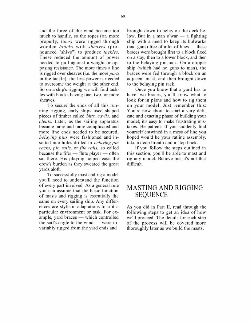
and the force of the wind became too much to handle, so the ropes (or, more properly, lines) were rigged through wooden blocks with sheaves (pro-nounced "shivs") to produce tackles. These reduced the amount of power needed to pull against a weight or op-posing resistance. The more times a line is rigged over sheaves (i.e. the more parts in the tackle), the less power is needed to overcome the weight at the other end. So on a ship's rigging we will find tack-les with blocks having one, two, or more sheaves.
To secure the ends of all this run-ning rigging, early ships used shaped pieces of timber called bitts, cavils, and cleats. Later, as the sailing apparatus became more and more complicated and more line ends needed to be secured, belaying pins were fashioned and in-serted into holes drilled in belaying pin racks, pin rails, or fife rails, so called because the fifer — flute player — often sat there. His playing helped ease the crew's burden as they sweated the great yards aloft.
To successfully mast and rig a model you'll need to understand the function of every part involved. As a general rule you can assume that the basic function of masts and rigging is essentially the same on every sailing ship. Any differ-ences are stylistic adaptations to suit a particular environment or task. For ex-ample, yard braces — which controlled the sail's angle to the wind — were in-variably rigged from the yard ends and
brought down to belay on the deck be-low. But in a man o'war — a fighting ship with a need to keep its bulwarks (and guns) free of a lot of lines — these braces were brought first to a block fixed on a stay, then to a lower block, and then to the belaying pin rack. On a clipper ship (which had no guns to man), the braces were fed through a block on an adjacent mast, and then brought down to the belaying pin rack.
Once you know that a yard has to have two braces, you'll know what to look for in plans and how to rig them on your model. Just remember this: You're now about to start a very deli-cate and exacting phase of building your model; it's easy to make frustrating mis-takes. Be patient. If you suddenly find yourself entwined in a mess of line you hoped would be your ratline assembly, take a deep breath and a step back.
If you follow the steps outlined in this section, you'll be able to mast and rig any model. Believe me, it's not that difficult.
MASTING AND RIGGING SEQUENCE
As you did in Part II, read through the following steps to get an idea of how we'll proceed. The details for each step of the process will be covered more thoroughly later as we build the masts,

61
1 — flying jib 2 — jib 3 — fore-topmast staysail 4 — foresail or fore course 5 — fore-lower topsail 6 — fore-upper topsail 7 — fore-topgallant sail 8 — fore-royal sail 9 — fore skysail
10 — fore-course studding sail 11 — fore-topmast studding sail 12 — fore-topgallant stuns'l 13 — fore-royal studding sail 14 — main staysail 15 — main-topmast staysail 16 — main-topgallant staysail 17 — main-royal staysail 18 — mainsail or main course 19 — main lower topsail 20 — main upper topsail 21 — main topgallant sail
22 — main royal sail 23 — main skysail 24 — main-topmast studding sail 25 — main-topgallant studding sail 26 — main-royal studding sail 27 — mizzen staysail 28 — mizzen-topmast staysail 29 — mizzen topgallant staysail 30 — mizzen-royal staysail 31 — crossjack 32 — mizzen lower topsail 33 — mizzen upper topsail 34 — mizzen topgallant sail 35 — mizzen royal sail 36 — mizzen skysail 37 — spanker 38 — gaff topsail 39 — mizzenmast 40 — mainmast 41 — foremast 42 — bowsprit
FIGURE 32. A fully rigged ship — lines and canvas galore.
62
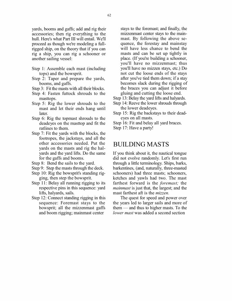
yards, booms and gaffs; add and rig their accessories; then rig everything to the hull. Here's what Part III will entail. We'll proceed as though we're modeling a full-rigged ship, on the theory that if you can rig a ship, you can rig a schooner or another sailing vessel:
Step 1: Assemble each mast (including tops) and the bowsprit.
Step 2: Taper and prepare the yards, booms, and gaffs.
Step 3: Fit the masts with all their blocks. Step 4: Fasten futtock shrouds to the
masttops. Step 5: Rig the lower shrouds to the
mast and let their ends hang until later.
Step 6: Rig the topmast shrouds to the deadeyes on the masttop and fit the ratlines to them.
Step 7: Fit the yards with the blocks, the footropes, the jackstays, and all the other accessories needed. Put the yards on the masts and rig the hal-yards and the yard lifts. Do the same for the gaffs and booms.
Step 8: Bend the sails to the yard. Step 9: Step the masts through the deck. Step 10: Rig the bowsprit's standing rig-
ging, then step the bowsprit. Step 11: Belay all running rigging to its
respective pins in this sequence: yard lifts, halyards, sails.
Step 12: Connect standing rigging in this sequence: Foremast stays to the bowsprit; all the mizzenmast gaffs and boom rigging; mainmast center
stays to the foremast; and finally, the mizzenmast center stays to the main-mast. By following the above se-quence, the forestay and mainstay will have less chance to bend the masts and can be set up tightly in place. (If you're building a schooner, you'll have no mizzenmast; thus you'll have no mizzen stays, etc.) Do not cut the loose ends of the stays after you've tied them down; if a stay becomes slack during the rigging of the braces you can adjust it before gluing and cutting the loose end.
Step 13: Belay the yard lifts and halyards. Step 14: Reeve the lower shrouds through
the lower deadeyes. Step 15: Rig the backstays to their dead-
eyes on all masts. Step 16: Fit and belay all yard braces. Step 17: Have a party!
BUILDING MASTS
If you think about it, the nautical tongue did not evolve randomly. Let's first run through a little terminology. Ships, barks, barkentines, (and, naturally, three-masted schooners) had three masts; schooners, ketches and yawls had two. The mast farthest forward is the foremast; the mainmast is just that, the largest; and the mast farthest aft is the mizzen.
The quest for speed and power over the years led to larger sails and more of them — and thus to higher masts. To the lower mast was added a second section
63
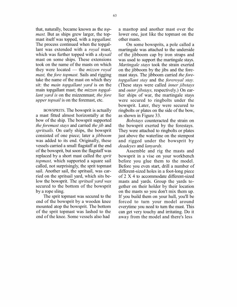
that, naturally, became known as the top-mast. But as ships grew larger, the top-mast itself was topped, with a topgallant. The process continued when the topgal-lant was extended with a royal mast, which was further topped with a skysail mast on some ships. These extensions took on the name of the masts on which they were located — the mizzen royal mast, the fore topmast. Sails and rigging take the name of the mast on which they sit: the main topgallant yard is on the main topgallant mast; the mizzen topgal-lant yard is on the mizzenmast; the fore upper topsail is on the foremast, etc.
BOWSPRITS. The bowsprit is actually a mast fitted almost horizontally at the bow of the ship. The bowsprit supported the foremast stays and carried the jib and spritsails. On early ships, the bowsprit consisted of one piece; later a jibboom was added to its end. Originally, these vessels carried a small flagstaff at the end of the bowsprit, but soon the flagstaff was replaced by a short mast called the sprit topmast, which supported a square sail called, not surprisingly, the sprit topmast sail. Another sail, the spritsail, was car-ried on the spritsail yard, which sits be-low the bowsprit. The spritsail yard was secured to the bottom of the bowsprit by a rope sling.
The sprit topmast was secured to the end of the bowsprit by a wooden knee mounted atop the bowsprit. The bottom of the sprit topmast was lashed to the end of the knee. Some vessels also had
a masttop and another mast over the lower one, just like the topmast on the other masts.
On some bowsprits, a pole called a martingale was attached to the underside of the jibboom cap by iron straps and was used to support the martingale stays. Martingale stays took the strain exerted on the jibboom by the jibs and the fore-mast stays. The jibboom carried the fore-topgallant stay and the foreroyal stay. (These stays were called inner jibstays and outer jibstays, respectively.) On ear-lier ships of war, the martingale stays were secured to ringbolts under the bowsprit. Later, they were secured to ringbolts or plates on the side of the bow, as shown in Figure 33.
Bobstays counteracted the strain on the bowsprit exerted by the forestays. They were attached to ringbolts or plates just above the waterline on the stempost and rigged under the bowsprit by deadeyes and lanyards.
Assemble and rig the masts and bowsprit in a vise on your workbench before you glue them to the model. Before you even start, drill a number of different-sized holes in a foot-long piece of 2 X 4 to accommodate different-sized masts and yards. Group the yards to-gether on their holder by their location on the masts so you don't mix them up. If you build them on your hull, you'll be forced to turn your model around everytime you need to turn the mast. This can get very touchy and irritating. Do it away from the model and there's less

64
FIGURE 33. Bowsprit rigging evolved as structural strength and more efficient use of the wind became increasingly important. Earlier bowsprits relied on rope fastenings; later bowsprits used metal fittings and chain rigging.
65
chance of breaking something you la-bored over.
Now that we've got a rough idea of what we'll be working on, let's get to it. As with any construction work, the key to success lies in following a logical order that allows the builder to move on with-out backtracking or painting himself into a corner. Masting and rigging a model requires sticking to a sequence that will simplify the operation and let you avoid subtle rigging maneuvers in hard-to-reach spots — of which there are many.
MAST PARTS
The masts support the yards, the sails, the booms and gaffs, and all the rigging needed to hold everything together and to move the sails to harness the wind. Kits will supply a number of pieces with which to construct your masts. Some parts may need painting or varnishing; check your plans and do this before you begin assembling the pieces.
TAPERING MASTS. Ship models use dowels for masts, and most kits supply them. Some dowels are walnut or some other dark wood; for models that require painted masts, kits will supply birch dowels. You'll still have to stain the upper masts, though, because on most ships this section was naturally finished with oil.
You'll likely run into some kind of problem with these dowels: Some are warped, some are precut and leave no
room on the ends to grip when you're tapering them, and some will be longer but require precise measuring to prevent waste — a difficult task at best. Chances are you'll have to buy extra dowels to get the job done properly.
Most masts are tapered toward the upper end; the sectional diameters are generally indicated in the plans. The best way to taper a mast is with a lathe. Un-fortunately, a lathe is quite an expensive machine and, at least for beginners working on their first couple of models, too much of an investment. Don't worry, I've found something that works pretty well: a 1/4-inch or 3/8-inch electric hand drill, a bastard machinist's file followed by a smoother mill file, and then sand-paper.
If you have no lathe and don't want to fork over the money for a variable-speed drill (although for $30 to $40 such a drill is worth the investment), you must reduce the drill's speed. Otherwise you'll break the dowel and most likely hurt yourself. You can build a variable-speed outlet by using a household light dim-mer (rheostat); but be careful not to run the drill at a reduced speed for more than 20 minutes at a time or you'll burn out its motor.
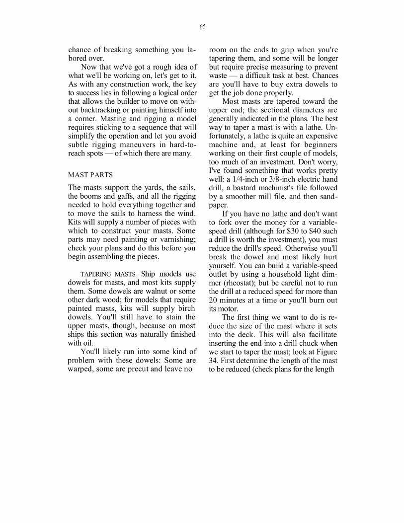
The first thing we want to do is re-duce the size of the mast where it sets into the deck. This will also facilitate inserting the end into a drill chuck when we start to taper the mast; look at Figure 34. First determine the length of the mast to be reduced (check plans for the length

66
FIGURE 34. Reducing the lower end of the mast.
of the mast below deck) and mark it by cutting a line around the mast with an X-Acto saw. Set the mast in a vise and file it flat (1). Next, turn the mast 90 degrees and set it in the vise with the flat side against one of the vise jaws. Flatten the second side and repeat this process until all four sides have been squared (2). Next file the corners, one at a time, until you reach the diameter needed (3 & 4). As you work, check for proper fit against holes in the deck. Now you can insert the reduced portion of the
mast in your drill or lathe and taper the other end as needed.
Set the mast in the drill chuck. (Even if the mast fits in the drill chuck without reduction, I prefer to reduce the lower end of every mast so I won't have to drill big holes in the deck planking.) Turn on the drill, and run a file across the mast's upper part while steadying the drill and the mast butt with your other hand. Use a glove so that the friction does not burn your fingers. The plans will indicate, for example, that the mast is 10 mm at the deck and 8 mm at its top. Measure the mast's diameter with a caliper while you reduce it. As you approach the proper diameter, switch to your smoother file. Once the proper taper is obtained with the file, sand the rough surface with a sanding board (which you can make by gluing a piece of fine sandpaper onto a paint mixing stick).
After the mast is tapered and sanded, you're ready to shape its upper part. If your model requires masts with the upper portions squared off, proceed as you did when you reduced the lower part to fit the deck hole, just don't round off the corners.
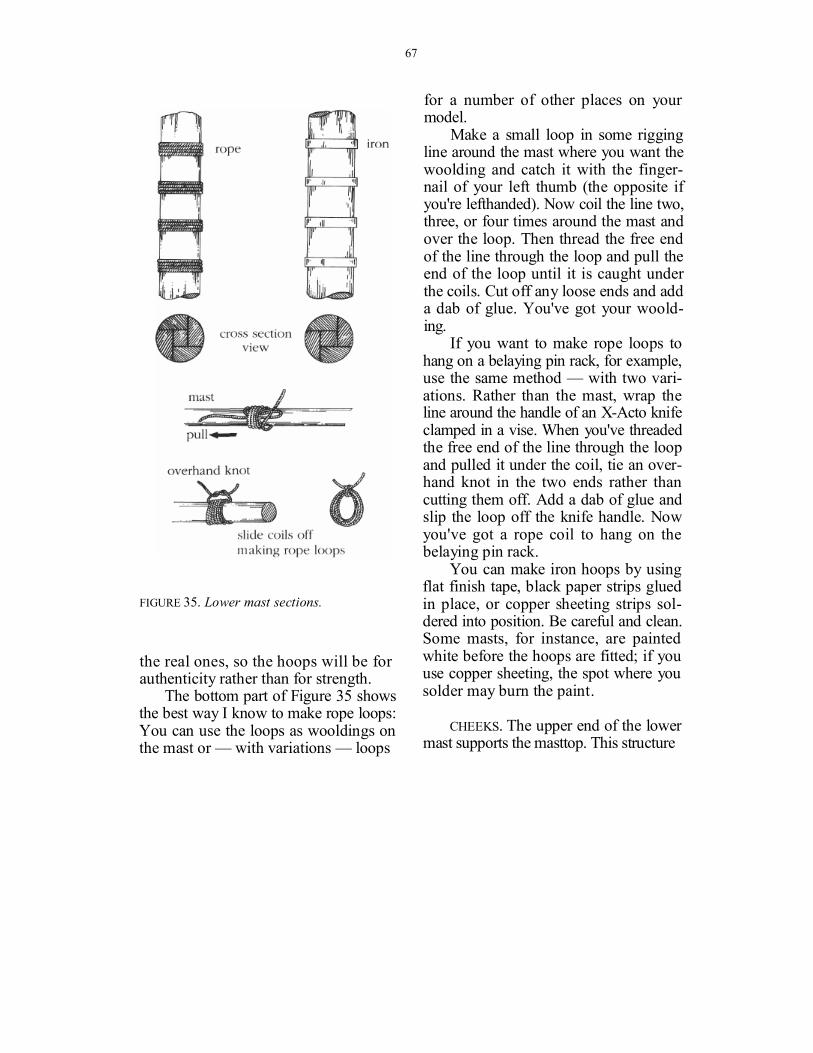
THE LOWER MAST. The lower mast is the heaviest, and in most cases it was built by woolding it — lashing together longitudinal sections with either rope or iron hoops (depending on the era in which the ship was built), as you can see in Figure 35. Of course, the masts on your model need not be made in sections like
67
FIGURE 35. Lower mast sections.
the real ones, so the hoops will be for authenticity rather than for strength.
The bottom part of Figure 35 shows the best way I know to make rope loops: You can use the loops as wooldings on the mast or — with variations — loops
for a number of other places on your model.
Make a small loop in some rigging line around the mast where you want the woolding and catch it with the finger-nail of your left thumb (the opposite if you're lefthanded). Now coil the line two, three, or four times around the mast and over the loop. Then thread the free end of the line through the loop and pull the end of the loop until it is caught under the coils. Cut off any loose ends and add a dab of glue. You've got your woold-ing.
If you want to make rope loops to hang on a belaying pin rack, for example, use the same method — with two vari-ations. Rather than the mast, wrap the line around the handle of an X-Acto knife clamped in a vise. When you've threaded the free end of the line through the loop and pulled it under the coil, tie an over-hand knot in the two ends rather than cutting them off. Add a dab of glue and slip the loop off the knife handle. Now you've got a rope coil to hang on the belaying pin rack.
You can make iron hoops by using flat finish tape, black paper strips glued in place, or copper sheeting strips sol-dered into position. Be careful and clean. Some masts, for instance, are painted white before the hoops are fitted; if you use copper sheeting, the spot where you solder may burn the paint.
CHEEKS. The upper end of the lower mast supports the masttop. This structure

68
FIGURE 36. Preparing the mast for cheek installation.
is supported by two shoulders, or cheeks, pegged to each side of the mast. (Most masts are cut square from the upper edge of the cheeks to the masthead. If your mast has a belaying pin ring, or a boom-supporting ring and brass sail hoops, insert it before setting the cheeks in place. Figure 36 shows how to ready a mast for the cheeks. First, file part of the upper section of the mast on each side to provide a flat surface for gluing the cheeks (1). Insert the squared end of the mast in the vise with the flattened top
edges of the cheeks resting on the vise jaws (2). If the mast is set at an angle (raked) on your model, make sure you set the mast in the vise at the same angle. This will allow the tops of the cheeks to remain parallel to the deck. For example, if the rake of the mast is 5 degrees, the angle between the back of the mast and the vise jaws will be 95 degrees.
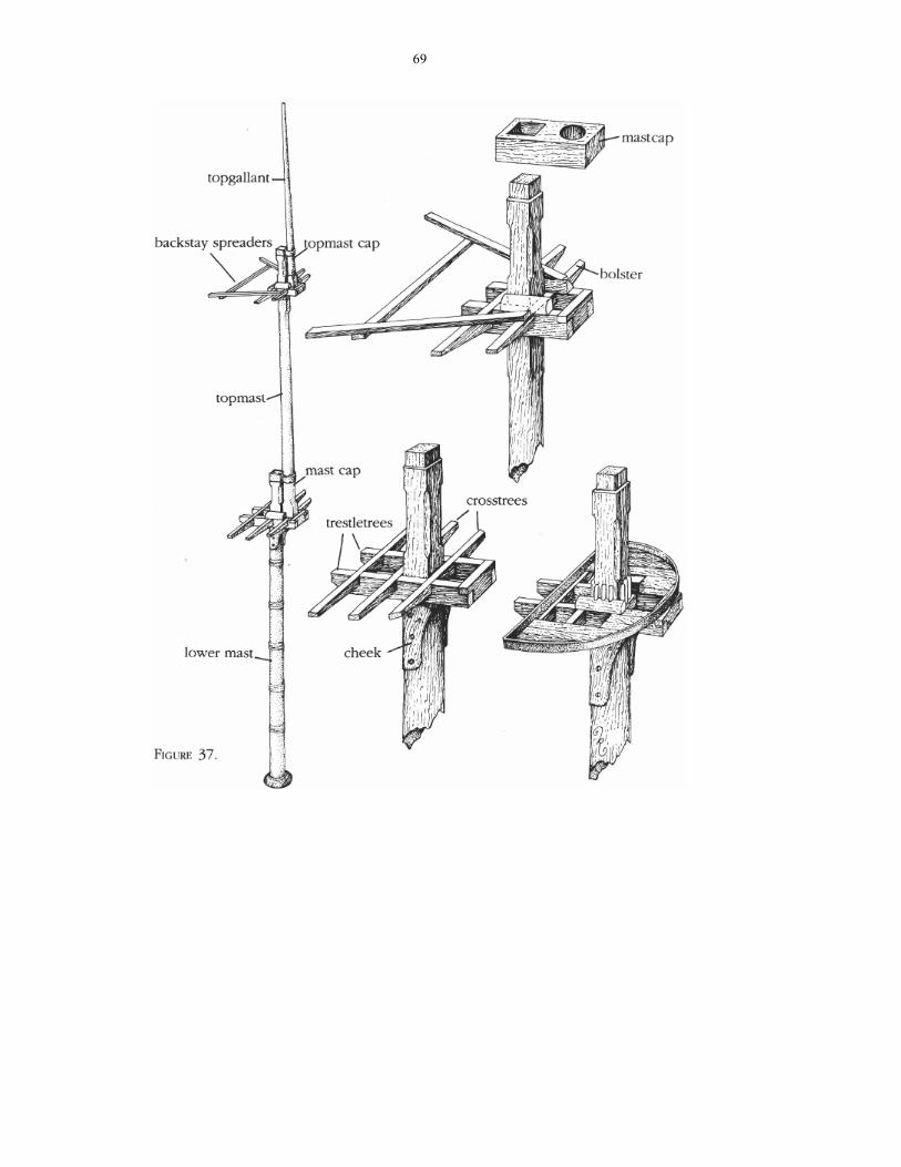
MASTTOPS. On top of the cheeks are set two timbers — one on each side of the mast running fore and aft — called trestletrees. Running athwartships and resting on the trestletrees are the crosstrees (two or more, depending on the type of ship). Finally, on top of the crosstrees and trestletrees, planks form the floor of the top.
There are many different types of masttops but, except for the ones on steel masts, all are built with crosstrees and trestletrees. Most kit plans have drawings ' of masttops and they are generally clear
FIGURE 37. Masts were a study in strength and utility. The lowest — and thickest — mast often was constructed from longitudi-nal sections banded together. At its top sat an assembly of crosstrees and trestletrees sup-ported by cheeks; this assembly was often planked over to provide a working platform. Moving up the mast you 'd find two more sections: the topmast (not the highest section as one would think), and then the topgal-lant. A mastcap held these two higher sec-tions together and helped support the top crosstrees assembly.
69

70
enough to understand. Some kits even supply precut trestletrees and crosstrees, so all you have to do is fit them and glue them together. Some precut pieces are not satisfactory because (and I've never understood why) they are cut cross-grain and break at the slightest touch. I never use cross-grained, precut pieces; I make my own from hardwood such as maple or boxwood and I suggest you do the same.
Crosstrees and trestletrees are notched together so their top edges are flush. Figure 37 will give you an idea how they work. The trestletrees are set and glued on top of the cheeks and against the sides of the mast. The spacing of the crosstrees, which run perpendicular to the trestletrees, depends on the model you're building.
To cut the notches on the trestletrees, insert the two pieces together in a vise (Figure 38); mark with a pencil where the slots are and extend a line to indi-cate the depth of the cuts. Make sure the two trestletrees are perfectly even and the line for the depth of cut is flush with the edge of the vise jaws. Using an X-Acto saw, cut down on the lines marked for the slots; then break the piece off by gently twisting the saw blade sideways. If the slots are slightly uneven use a small file to clean the cuts. Repeat the process for the crosstrees.
Match the different pieces together to check that they fit properly and that they are flush on the upper side, where the planking will be applied. Then ap-
FIGURE 38. Precision cutting is vital when aligning crosstrees and trestletrees; a vise helps.
ply some glue in the slots and press the pieces together.
Another part of the top's framing consists of bolsters, wood blocks rounded on one side to provide a smooth surface on which the shrouds can rest (see Fig-ure 37). You can make bolsters by filing one corner of a square piece of stock, or you can buy quarter-round molding in a hobby shop.
It's most important to ensure that everything is perfectly flat and that no distortions occur while the glue is drying. To do this, sandwich the entire structure between two pieces of scrapwood and clamp the whole thing together until the glue dries.
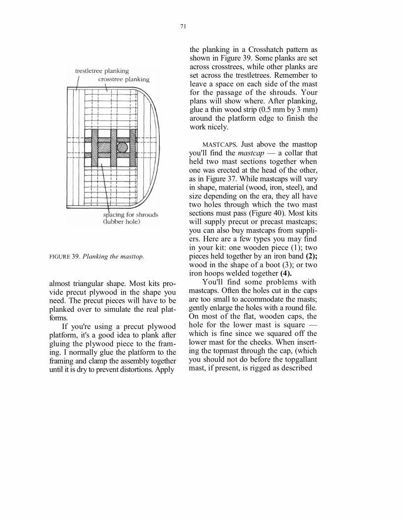
MASTTOP PLANKING. The framework of crosstrees and trestletrees was covered with planking to provide a working plat-form. The top's platform changed over time from the original round shape on early vessels to a rectangular and later
71
FIGURE 39. Planking the masttop.
almost triangular shape. Most kits pro-vide precut plywood in the shape you need. The precut pieces will have to be planked over to simulate the real plat-forms.
If you're using a precut plywood platform, it's a good idea to plank after gluing the plywood piece to the fram-ing. I normally glue the platform to the framing and clamp the assembly together until it is dry to prevent distortions. Apply
the planking in a Crosshatch pattern as shown in Figure 39. Some planks are set across crosstrees, while other planks are set across the trestletrees. Remember to leave a space on each side of the mast for the passage of the shrouds. Your plans will show where. After planking, glue a thin wood strip (0.5 mm by 3 mm) around the platform edge to finish the work nicely.
MASTCAPS. Just above the masttop you'll find the mastcap — a collar that held two mast sections together when one was erected at the head of the other, as in Figure 37. While mastcaps will vary in shape, material (wood, iron, steel), and size depending on the era, they all have two holes through which the two mast sections must pass (Figure 40). Most kits will supply precut or precast mastcaps; you can also buy mastcaps from suppli-ers. Here are a few types you may find in your kit: one wooden piece (1); two pieces held together by an iron band (2); wood in the shape of a boot (3); or two iron hoops welded together (4).
You'll find some problems with mastcaps. Often the holes cut in the caps are too small to accommodate the masts; gently enlarge the holes with a round file. On most of the flat, wooden caps, the hole for the lower mast is square — which is fine since we squared off the lower mast for the cheeks. When insert-ing the topmast through the cap, (which you should not do before the topgallant mast, if present, is rigged as described

72
FIGURE 40. Mastcap components.
below) keep it in line with the lower mast. The distance between the two holes (5) should be equal to the space between the two masts at the top level. Normally this distance is equal to the thickness of the crosstree. If the type of top you're making does not have a crosstree in that location, you'll have to insert a wood spacer, called a chock (6); note also the bolster.
CROSSTREES. Moving up the mast we come to an arrangement similar to the masttop, but now called the crosstrees, which connects the upper portion of the topmast to the lower part of the topgal-lant mast. Here the frame is not covered with planks. Since the upper side of the timbers does not need to be flush, the notches can be cut smaller to give the crosstrees more strength, as shown in

73
FIGURE 41. Finishing the mast.
Figure 41. Drill a hole into the ends of the crosstrees to take the futtock shrouds, according to your plans.
Fit the cap on the topgallant mast. Then join the topgallant to the topmast, making sure the two are aligned. Use carpenter's glue on all parts, along with a very small dab of ACC to hold them together.
Next, affix the topmast and topgal-lant assembly to the lower mast. While gluing these two components together, check that the crosstrees are aligned with the top. Also make sure that the whole assembly is straight. The mast is now ready to be furbished with blocks and eyebolts.
Set the mast aside until later.
PHOTO 23. The masttop of a schooner. No-tice the small rings below the deadeyes at the ends of the crosstrees. The futtock shrouds will be tied to these rings after the main shrouds are rigged.
YARDS
Yards are spars suspended horizontally from the masts to stretch the sails to the wind. Figure 42 shows yards and how to taper them.
The yards on early ships (17th and 18th century) had a thick octagonal center portion and were rounded and tapered toward the ends. The thicker section provided a better gripping sur-face for slings and jeers — which held

74
FIGURE 42. Tapering yards.
the yards to the masts and allowed them to be adjusted to the wind. In later ships, as the methods to secure and move the yards improved, the middle portion was rounded like the rest of the yard, and the tapering ran almost from the middle to the ends (1).
Most kits supply a number of dow-els (birch, walnut, lemonwood, etc.) from which to make the yards. The yards often must be cut from dowels of varying lengths. Just as with the masts, you'll often run short and have to buy extras.
TAPERING YARDS. As with the masts, the process of tapering is made a lot easier with a lathe. But if you don't have one, and there's really no reason for you to rush out and get one, you can still do
a good job of tapering. The trick is to cut the dowel longer than you need (2), leaving a portion on each end to grip in a vise, lathe, or a drill chuck.
One way to taper the yards is to use your variable-speed electric drill or your current-reduction rheostat (again, no more than 20 minutes with this or you'll burn out your drill's motor), and the bastard machinist's file and the smoother mill file for finishing. Just leave the extra length at one end to fit into the drill chuck and sand away. When you're done, cut off the extra amount on each end.
If your yard is the earlier type with the unrounded, thicker middle, you can build this up by gluing eight strips about 0.5 mm thick around the yard, and then tapering their ends.

75
FIGURE 43. Wind changes direction, hulls pitch and roll, and fore-and-aft sails must be raised and lowered. To allow the spars supporting these sails to rise, drop, and pivot while secured to the mast we have jaws, boom rests, and parrels.
BOOMS AND GAFFS
Booms and gaffs take the place of yards for fore-and-aft rigged sails. On a schooner, booms and gaffs hold up the fore- and mainsails. On a square rigger a boom and a gaff support the foot and head (respectively) of the spanker, or driver. Unlike yards, they are often ta-pered only on one end. These spars are
secured to the mast by a fork-like exten-sion called jaws, as shown in Figure 43. The jaws encircle the after half of the mast circumference and are secured around the forward half by a parrel— a rope inserted through round beads and tied at each end of the jaws.
The boom is supported at the mast by a wooden collar called a boom rest. This is glued to the mast and supported

76
by small wooden brackets. The jaws can be built and installed
on the boom and the gaff in more than one way. One method is to cut the jaws from a piece of solid wood of the proper size and make a "throat" at the larger end so that it will fit halfway around the mast. This can be done either with a jigsaw or with a round file. Next, cut a slot on the boom end the size of the jaw piece and insert the jaw in it. Wind a small dark (to simulate tar) rigging line around the joint — a process called serving — to make the works more realistic.
Another method is to file a flat on either side of the boom or gaff end. Then cut two pieces of wood to the shape of half jaws and glue them to the flats. For realism you can drill two or three holes on each side and insert pins.
When rigging the gaff and boom parrels around the mast try this method: Tie an overhand knot on one end of the black rope and insert the rope in the hole at one side of the jaws. Next, insert the beads in the rope. To prevent the beads from rolling off, apply a little glue on the rope where the beads will stay. Next, set the jaws against the mast and thread the rope through the other hole in the jaws. Put a dab of fast-setting glue on the rope right on the spot where it will set in the hole; everything will stay taut.
Some ships built after around 1812, such as clippers, carried a spencer mast — a small-diameter mast that ran up the after side of the mizzenmast deck to masthead (Figure 44). It was secured at
FIGURE 44. The smaller spencer mast made it easier to attach gaffs.
the top through a hole in the mizzen, in chocks between the trestletrees, or to an iron band around the mizzenmast. At the lower end it passed through a hole cut in a wooden collar which was secured to the mizzenmast and also served as a boom rest. The butt was then inserted into a hole in the deck. Some ships had spencer masts abaft the fore- and main-sails as well; these carried fore-and-aft rigged spencer sails similar to the

77
spanker. The spencer masts provided a smaller spar for gaff jaws and hoops to have to encircle.
RIGGING THE SPARS
Here's a word of comfort — and one of caution — before we get started. Before we step the masts, we'll attach all the necessary rigging. That's going to create a temporary mess. Once you've rigged the masts and their fittings — the booms, the yards, the gaffs, and the sails — you'll have a lot of lines hanging down until you secure everything on the hull. If you separate the groups of lines and tape them together everything will become much simpler to identify. For example, tape the lower shrouds together at the bottom and they will not tangle with the rest of the lines.
Before we get into the actual rigging sequence, it's important to understand some terms vital to working with rope. When we talk about "securing and fit-ting the shrouds" or "rigging the main-stay," you'll be doing something involv-ing the following:
To belay a line means secure it, in this context usually to a belaying pin on a bulwark.
To reeve a line is to lead it through a hole or a pattern of holes, in this con-text usually through deadeyes or sheaves.
To seize a line means permanently lashing two lines (or two parts of the
FIGURE 45. Blocks, relatively simple mecha-nisms on which the entire movement of a ship rests.
same line) together using small stuff— short lengths of smaller rope. When you fit a shroud to a mast you may wrap the shroud around the mast and then seize its end back on itself. Seizing is a com-plicated and exacting craft, especially on a model. And intricate seizing is not something at which a beginner should

78
try his hand. We'll keep it simple: When I say "seize it," I mean use a simple overhand knot, a few wraps, and a dab of glue.
To serve a line means to wrap it tightly with small stuff to protect it from chafing.
Blocks and rigging line were small enough on life-size ships to accommo-date human hands; when you're work-ing in scale they become painfully tiny. In 1/8-inch scale a foot-long block is only 1/8-inch (or 3 mm) long. Even the thick-est of shrouds becomes quite thin in scale. Blocks furnished with kits usually are out of scale; sometimes you'll get only one size. Choose your rigging line care-fully, and make every effort to keep within scale: You can buy rigging line as small as 0.10 mm (.004 inch).
Standing rigging was tarred; use black line for that. Running rigging, which sailors handled, was not tarred; use cream or tan line for that.
RIGGING SEQUENCE Step 1: Fit masts with blocks. Step 2: Rig the futtock shrouds. Step 3: Rig the lower shrouds. Step 4: Rig the topmast shrouds. Step 5: Rig the topgallant shrouds. Step 6: Fit the ratlines to the upper
shrouds (called "rattling down"). Step 7: Brush diluted glue over knots. Step 8: Fit the yards with the blocks, the
footropes, and the jackstays. Step 9: Bend the sails (if you're using
them) to the yards.
Step 10: Put the yards on the masts and rig the halyards and the yard lifts. Do the same for the gaffs and boom.
Step 11: Affix the booms, gaffs and spen-cer masts.
Step 12: Step the masts. Step 13: Rig, fit, and step the bowsprit.
BLOCKS. The first step in rigging your model calls for attaching blocks to the various spars. The exact arrangement of blocks and eyebolts depends on the ship you're building. Take a look at the plans and determine:
• Whether you need holes in the masts for halyard sheaves, or whether the halyards are rove through blocks instead;
• Where you'll install the blocks for the yard lifts;
• Where, if you need them, you'll put the lower yard trusses and the lower topsail yard cranes;
• Where you'll install the cleats or sup- ports for the yards' sling chains;
• Where you put the blocks for the peak and throat halyards for gaffs.
Makes it sound like you'll be look-ing for obscure parts for the rest of the day, doesn't it? It's really not as involved as it seems; just follow the plans.
Look for oval-shaped blocks made from hardwood such as maple, oak, or boxwood. It's possible to make your own blocks, but that's a process best reserved for later. If you're building a large-scale
79
model, you can buy blocks that already have sheaves in them.
Blocks are made of shaped wooden pieces (see Figure 45) held together by a strap made of rope on earlier ships, metal on later ships. On some blocks (maybe as many as 50 percent) you'll find an iron ringbolt, or becket, riveted to the strap. On the other end of the strap is either a rope tail or an iron hook, de-pending on the era and the block's spe-cific job. A sheave (a grooved insert on which the line will move — a pulley), held in place by an iron pin that goes through the cheeks and the iron strap, is inserted in the space between the two cheeks.
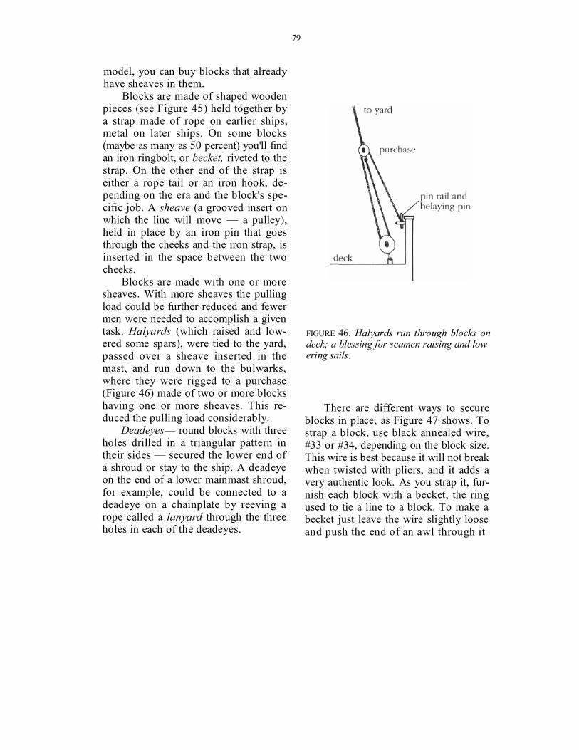
Blocks are made with one or more sheaves. With more sheaves the pulling load could be further reduced and fewer men were needed to accomplish a given task. Halyards (which raised and low-ered some spars), were tied to the yard, passed over a sheave inserted in the mast, and run down to the bulwarks, where they were rigged to a purchase (Figure 46) made of two or more blocks having one or more sheaves. This re-duced the pulling load considerably.
Deadeyes— round blocks with three holes drilled in a triangular pattern in their sides — secured the lower end of a shroud or stay to the ship. A deadeye on the end of a lower mainmast shroud, for example, could be connected to a deadeye on a chainplate by reeving a rope called a lanyard through the three holes in each of the deadeyes.
FIGURE 46. Halyards run through blocks on deck; a blessing for seamen raising and low-ering sails.
There are different ways to secure blocks in place, as Figure 47 shows. To strap a block, use black annealed wire, #33 or #34, depending on the block size. This wire is best because it will not break when twisted with pliers, and it adds a very authentic look. As you strap it, fur-nish each block with a becket, the ring used to tie a line to a block. To make a becket just leave the wire slightly loose and push the end of an awl through it

80
FIGURE 47. Securing blocks.
after the wire is twisted on the other end of the block (1).
To attach a block to a line (such as a short rope tail or pendant on the end of a yard) you can either wrap the rope around the block and seize the end back on itself with fine thread (2), or strap the block with wire, insert the rope between the wire ends, and twist the wire a few
PHOTO 24. Blocks rigged with wire. Notice the tip of the awl inserted in the block's becket.
more turns (3). Then wrap the short end of the rope around the twisted part of the wire and the rope itself, and apply a dab of glue to it. Cut the excess wire.
Varnish all your blocks after you've installed them.
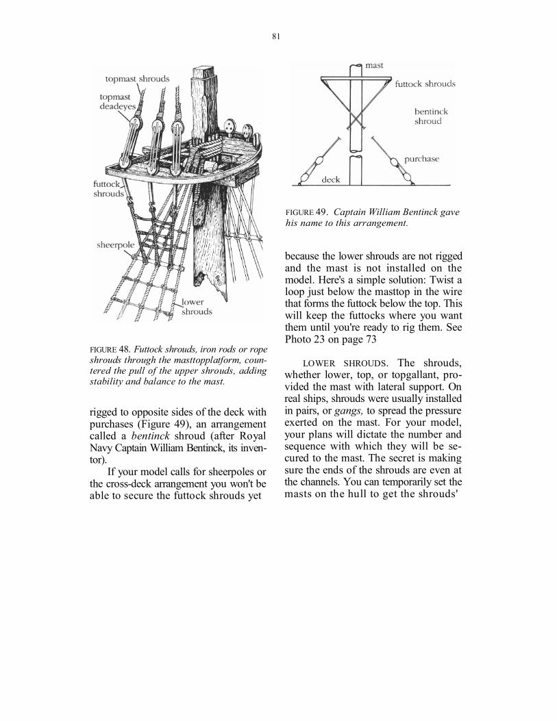
FUTTOCK SHROUDS. Futtock shrouds, if present, are short iron rods (or ropes on ships built prior to about 1820) that secure the topmast shrouds to the deadeyes. There are a number of ways they can be installed, as Figure 48 shows. Depending on the model you're con-structing, the futtock shrouds will be secured either to an iron mastband or to a sheerpole tied to the lower shrouds. On some ships the topmast futtock shrouds were tied to lines that were
81
FIGURE 48. Futtock shrouds, iron rods or rope shrouds through the masttopplatform, coun-tered the pull of the upper shrouds, adding stability and balance to the mast.
rigged to opposite sides of the deck with purchases (Figure 49), an arrangement called a bentinck shroud (after Royal Navy Captain William Bentinck, its inven-tor).
If your model calls for sheerpoles or the cross-deck arrangement you won't be able to secure the futtock shrouds yet
FIGURE 49. Captain William Bentinck gave his name to this arrangement.
because the lower shrouds are not rigged and the mast is not installed on the model. Here's a simple solution: Twist a loop just below the masttop in the wire that forms the futtock below the top. This will keep the futtocks where you want them until you're ready to rig them. See Photo 23 on page 73
LOWER SHROUDS. The shrouds, whether lower, top, or topgallant, pro-vided the mast with lateral support. On real ships, shrouds were usually installed in pairs, or gangs, to spread the pressure exerted on the mast. For your model, your plans will dictate the number and sequence with which they will be se-cured to the mast. The secret is making sure the ends of the shrouds are even at the channels. You can temporarily set the masts on the hull to get the shrouds'

82
FIGURE 50. Rigging lower shrouds.
length. Cut all shrouds about 3 inches longer than the measured distance be-cause you'll need the extra length when you tie them to the deadeyes before reeving the lanyards. See Figure 50. Run the shroud around the lower mast above the trestletrees and drop and tape both ends evenly (1) just below where they will attach to the channels when the masts are stepped. Figure 50 shows how the shrouds will look when the masts are placed on the hull. Take an alligator clip and place it on the shrouds just below the trestletrees — this will keep them from slipping. With a simple overhand knot in a short section of a separate piece of rigging line, tie the shrouds just above the trestletrees (see Figure 48 on page 81); apply a dab of glue (2). Tape or clip the lower ends together until later. Al-ternate sides with each pair of shrouds.
TOPMAST AND TOPGALLANT SHROUDS. Apply the same method to the topmast shrouds. Run the shrouds around the topmast above the masthead crosstrees, clip, seize above the clip, glue the seizing knot.
The next step is to rig the lower ends of the topmast shrouds to the topmast deadeyes, if these are present; then you'll be able to install the topgallant shrouds. Here again, however, you will find dif-ferent construction details from ship to ship. On some, the topmast shrouds are rigged via deadeyes through the tops to the futtock shrouds, as in Figure 48. On others (Figure 51), the shrouds pass through ho les in th e ends o f the

83
FIGURE 51. Topmast deadeye assemblies. FIGURE 52. Upper ratlines.
crosstrees, becoming the futtocks, and are tied to a ring on the mast band; the deadeyes are dispensed with. In the lat-ter case, belay the shrouds to the mast band. In the former case, once the top-mast shrouds are seized to the deadeyes, it's time to reeve lanyards through the upper and lower deadeyes of each pair; a simple technique for this can be found under "An Easy Way," page 100.
This is the time to set up the topgal-lant shrouds, which will seem straight-forward after the topmast shrouds.
RATLINES. Now is the time to rattle down the upper shrouds. Use an over-hand knot to tie the ratlines — the rope ladders sailors use to climb the masts —
to the shrouds (see Figure 52). At model size, this knot looks better than the tra-ditional clove hitch because it is simpler and neater (1). Ratlines were not tarred, thus the rigging line you'll use for rat-lines is cream-colored — and smaller than any other rigging line you'll use on the model. The vertical distance between the ratlines on a real ship was usually 16 inches, which works out to around 3/16 of an inch on a 1/8-inch scale model. I judge this distance by eye, but you can also slip a strip of wood between the lines for proper spacing. To turn the line around the shroud I first make a loop, then push the loop behind the shroud and catch it on the other side with a crochet hook (2). Leave a short piece of

84
FIGURE 53. Basic yard blocks.
rigging line on the end knots to be cut later.
When you've rattled down the upper shrouds, paint everything with diluted carpenter's glue and let it dry. The glue will secure the knots and stiffen the whole assembly. Now cut the ratline ends with a very sharp pair of scissors. Once this is done your masts are ready for their yards.
YARDS — BASIC RIGGING
The yards are fitted with many gadgets to provide for their proper operation, including any number of blocks. The details will vary depending on the era and the type of vessel. Yards were also fitted with basic running tackle to lift and
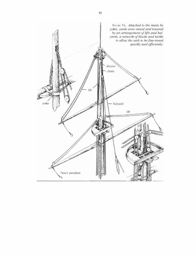
lower, orient, and support the yards on the masts. Figures 53 and 54 show the complexity of rigging yards. And that's not all — yards have a number of other accessories.
Now that the masts have been fitted with their blocks, the lower shrouds have been seized, and the upper shrouds have been rattled down, we can furbish the yards with yokes, parrels, or slings, as indicated in your plans.
Yards (topmast, topgallant, royal, etc.) that have no fixed yokes or trusses should be pinned to the masts to keep them from sliding up and down.
Figure 55 shows some accessories.
YARD BANDS. Iron bands with eyes were used on some vessels to secure the
85

86
blocks to the yard. Make yard bands with black paper or copper sheathing, with little eyebolts inserted through drilled holes (1), or with ropes (thread) with small loops tied into them (2). In small models, use the tails of the wires that strap the block to simulate the bands (3). Pay close attention to your plans for the number, size, and location of every block on the yard.
A little calmness reminder: Make sure the blocks in your kit are the correct sizes before installing them. Chances are they won't be.
SHEAVES. Sheaves are inserted in a yard or a mast to provide a smooth pas-sage for a rigging line (4). To install a sheave, drill two or three holes as re-quired to form a cut long and wide enough to receive the sheave. Cut across the holes until you obtain the space needed. Then drill a small hole across the cut and insert the sheave in the slot and pin in the hole to hold the sheave in place.
FOOTROPES. When sailors had to move out on the yards to tend the sails, they stepped on footropes suspended about three feet below the yards and supported by other ropes called stirrups (5). If the yard carried stunsail booms additional footropes called Flemish horses were installed at its end.
Manuals and kit plans suggest a variety of methods for fitting footropes.
I've found that the following method works well for me: Use black rigging line for the stirrups and cream-colored line for the footropes. For the stirrups, tie a clove hitch around the yard (6) and secure the knot with a touch of glue. Cut off the upper end. Tie an overhand knot on the lower end of the line, insert the footrope in the overhand knot and se-cure it with a touch of glue. Make fast the ends of the footropes to the yards with a clove hitch.
JACKSTAYS. Sails were held to yards by lacing them to jackstays on the yards' upper sides. Until the early 19th century jackstays were made of rope laced through eyebolts screwed to the top of the yard. Later the rope was changed to an iron rod (7). Jackstays served a sec-ond purpose — and one that preserved the life of more than one sailor aloft — a solid place to grip. For your model, either build up the jackstays from eye-bolts and rope or wire, or use stamped jackstays, which you can buy from sup-pliers.
To install the jackstays, hold the yard in a vise and mark the spots for the eyebolts. Drill holes and glue the eye-bolts. If your model requires a rope jack-stay, thread some cream-colored rigging line through the eyebolts, applying a spot of glue to each of them. If your model requires an iron rod, use model airplane steel wire, threading it through the eye-bolts and soldering the ends. The steel rod looks best painted black.

87
FIGURE 55. Yard accessories.
88
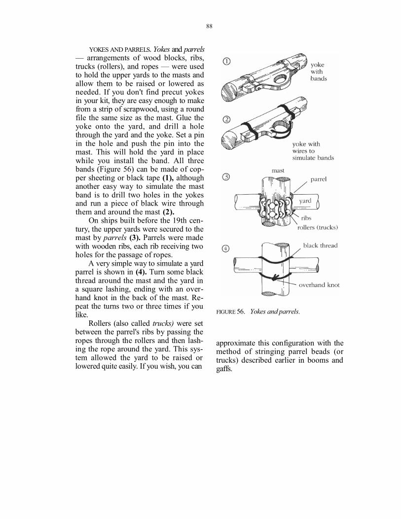
YOKES AND PARRELS. Yokes and parrels — arrangements of wood blocks, ribs, trucks (rollers), and ropes — were used to hold the upper yards to the masts and allow them to be raised or lowered as needed. If you don't find precut yokes in your kit, they are easy enough to make from a strip of scrapwood, using a round file the same size as the mast. Glue the yoke onto the yard, and drill a hole through the yard and the yoke. Set a pin in the hole and push the pin into the mast. This will hold the yard in place while you install the band. All three bands (Figure 56) can be made of cop-per sheeting or black tape (1), although another easy way to simulate the mast band is to drill two holes in the yokes and run a piece of black wire through them and around the mast (2).
On ships built before the 19th cen-tury, the upper yards were secured to the mast by parrels (3). Parrels were made with wooden ribs, each rib receiving two holes for the passage of ropes.
A very simple way to simulate a yard parrel is shown in (4). Turn some black thread around the mast and the yard in a square lashing, ending with an over-hand knot in the back of the mast. Re-peat the turns two or three times if you like.
Rollers (also called trucks) were set between the parrel's ribs by passing the ropes through the rollers and then lash-ing the rope around the yard. This sys-tem allowed the yard to be raised or lowered quite easily. If you wish, you can
FIGURE 56. Yokes and parrels.
approximate this configuration with the method of stringing parrel beads (or trucks) described earlier in booms and gaffs.
89
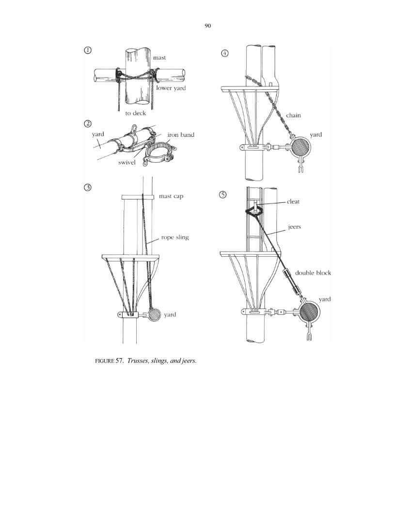
TRUSSES, SLINGS, AND JEERS. A number of methods were developed to hold the lower yards in place and allow them to be adjusted to the wind, as shown in Figure 57. Trusses allowed the lower yards to be adjusted laterally. On older ships, trusses were made of rope turned around the mast (1) and the yard and brought down to the deck, where they were secured with a purchase — tackle arranged to mechanically increase the force a sailor could apply. Later trusses were made of iron. An iron band with a swivel joint holding the yard was secured around the mast (2). This allowed the yard to be oriented to the wind as needed.
The weight of the yard was sup-ported by a sling. Before the 19th cen-tury, the sling was made of heavy rope turned over the mastcap, fed through the masttop and tied to the center of the yard (3). Later, a chain was used instead, and it was turned over a cleat behind the mast and fitted to an iron band on the middle of the yard (4).
On older vessels, jeers also were used to raise or lower the yards for re-pairs as needed. Jeers were lines hung to the mast on a rope sling supported on each side by wooden cleats. A double block hung on the end of the sling and another double block was seized to the yard. The fall of this tackle was then brought to the deck, where it was rigged to another purchase and secured to be-laying pin racks. The jeers were set in pairs, one on each side of the mast (5).
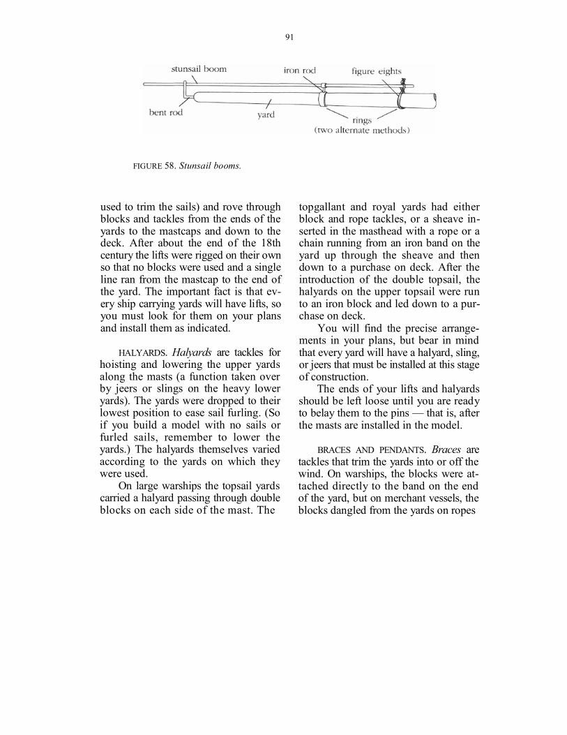
STUNSAIL BOOMS. Stunsails were small sails carried by some ships on the ends of their yards to aid light-air performance. These sails were held by stunsail booms that extended the length of the yards, as we see in Figure 58.
Stunsail booms were supported by two iron rings. The inside ring wrapped around the boom and was fixed to a short iron rod that ran to another ring secured to the yard. The one on the end of the yard was supported by a bent iron rod inserted into the yard end. These rings are sometimes supplied in the kits, but if not, you can make your own. Here are some simple ways to make them. For the one at the end, use brass wire. Bend it over the tip of a pair of roundnose pliers or over a dowel of the right size to form the ring, and then bend the wire. You can also cut the ring from brass tubing and solder it to a brass wire.
The inside iron can be made in dif-ferent ways. One way is to cut two rings from brass tubing and solder them to-gether. Another is to flatten a piece of brass wire with a hammer, shape it into two rings and then solder them together. Still another way is to use #32 black annealed wire and bend it over the yard and the stunsail boom in a figure-eight fashion (two or more turns) and then twist the ends below the yard.
LIFTS. Lifts are tackles that support the weight of the ends of the yards and hold them horizontal. On earlier ships the lifts were combined with sheets (lines
90
FIGURE 57. Trusses, slings, and jeers.
91
FIGURE 58. Stunsail booms.
used to trim the sails) and rove through blocks and tackles from the ends of the yards to the mastcaps and down to the deck. After about the end of the 18th century the lifts were rigged on their own so that no blocks were used and a single line ran from the mastcap to the end of the yard. The important fact is that ev-ery ship carrying yards will have lifts, so you must look for them on your plans and install them as indicated.
HALYARDS. Halyards are tackles for hoisting and lowering the upper yards along the masts (a function taken over by jeers or slings on the heavy lower yards). The yards were dropped to their lowest position to ease sail furling. (So if you build a model with no sails or furled sails, remember to lower the yards.) The halyards themselves varied according to the yards on which they were used.
On large warships the topsail yards carried a halyard passing through double blocks on each side of the mast. The
topgallant and royal yards had either block and rope tackles, or a sheave in-serted in the masthead with a rope or a chain running from an iron band on the yard up through the sheave and then down to a purchase on deck. After the introduction of the double topsail, the halyards on the upper topsail were run to an iron block and led down to a pur-chase on deck.
You will find the precise arrange-ments in your plans, but bear in mind that every yard will have a halyard, sling, or jeers that must be installed at this stage of construction.
The ends of your lifts and halyards should be left loose until you are ready to belay them to the pins — that is, after the masts are installed in the model.
BRACES AND PENDANTS. Braces are tackles that trim the yards into or off the wind. On warships, the blocks were at-tached directly to the band on the end of the yard, but on merchant vessels, the blocks dangled from the yards on ropes

92
or chains called pendants. Get the yards ready for the braces by attaching the blocks now. To ease the final rigging process, the braces themselves won't be rigged until we've stepped the masts. (See page 106.)
GAFF RIGGING. The gaff rigging con-sists of a throat halyard and a peak hal-yard. The throat halyard lifts or lowers the gaff along the mast and consists of two blocks (single, double, or triple depending on the size of the gaff) — one secured to the jaws and the other under the masttop. The fall from this tackle is belayed on the fife rail.
The peak halyard supports the end of the gaff and the sail. This halyard of-ten is rove through two single blocks seized on top of the gaff at a set distance from each other and two more single blocks secured on the mast above the masttop. The end of the gaff is always peaked up to follow the cut of the up-per edge of the sail. The gaff is lowered when the sails are furled on the boom. The gaff is controlled from the deck by vangs — lines rove through a pair of double blocks attached by pendants to the tip of the gaff and belayed to a cleat on each bulwark. Vangs kept the gaff from sagging off to leeward.
BOOM RIGGING. The boom is sup-ported on its after end by the topping lift. An eyebolt is secured by an iron band to the boom. A rope pendant runs from the eyebolt to a block about halfway
toward the masttop. The topping lift rigging starts at the becket of a block secured to an eyebolt just below the masttop; it reeves through the block on the pendant, back through the block at the masttop, then down to belay on the pinrail.
BOWSPRIT RIGGING. Think of a bow-sprit as nothing more than a mast that's leaning forward. Take a look at Figure 33 on page 64 to see the variations in bowsprit rigging. As with the masts, rig and fit your bowsprit on the workbench, not the hull.
Like the lower mast, the bowsprit is hooped. Up until about the mid-19th century a gammon lashing held it to the stempost of the ship. Later the rope gammoning was replaced with iron or chain.
The jibboom is fixed to the bowsprit by a cap and gammoning. Depending on the era of your model the jibboom stays were either rope or chain. Bobstays — which counteracted the lift of the fores-tay — were originally heavy rope, evolv-ing into chains or iron bands. Likewise for martingale stays — which counter-acted the lift of the headstays.
The spritsail yard was secured to the bottom of the bowsprit by a rope sling. Fit eyebolts on the upper side of this yard through which to reeve the spritsail stays. Later, these stays can be fixed to the deadeyes outboard of the bow.
Like any other yard, the spritsail yard will require lifts and braces — it may also
93
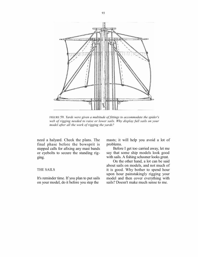
FIGURE 59. Yards were given a multitude of fittings to accommodate the spider's web of rigging needed to raise or lower sails. Why display full sails on your model after all the work of rigging the yards?
need a halyard. Check the plans. The final phase before the bowsprit is stepped calls for afixing any mast bands or eyebolts to secure the standing rig-ging.
THE SAILS
It's reminder time. If you plan to put sails on your model, do it before you step the
masts; it will help you avoid a lot of problems.
Before I get too carried away, let me say that some ship models look good with sails. A fishing schooner looks great.
On the other hand, a lot can be said about sails on models, and not much of it is good. Why bother to spend hour upon hour painstakingly rigging your model and then cover everything with sails? Doesn't make much sense to me.

94
PHOTO 25. Sails are rigged to the yards with a running stitch — a relatively simple operation. Notice how a furled sail can help you show off your rigging.
It's quite impossible to find fabric that is thin enough to be in scale with your model; even if you could it would be next to impossible to sew it with a sew-ing machine.
Not to belabor the point, but here's another thing: To be installed properly, sails require a lot more rigging lines. All these extra lines must be belayed on belaying pin racks that are already bris-tling with belaying pins. Each sail will need sheets, buntlines, leechlines, and clewlines: that's eight lines going to the belaying pin racks. If you are rigging a clipper ship every mast will carry five
sails; you'll need at least 40 extra belay-ing pins on the racks. In such a small scale, that's impossible.
The sails take their name from the yard or the stay to which they are rigged. You may find a lower main staysail or a topgallant sail as well as stunsail, jib-boom staysail, and a spritsail. You could find as many as 38 pieces of canvas (sails) on a clipper ship. Lots of fun — if you like to sew!
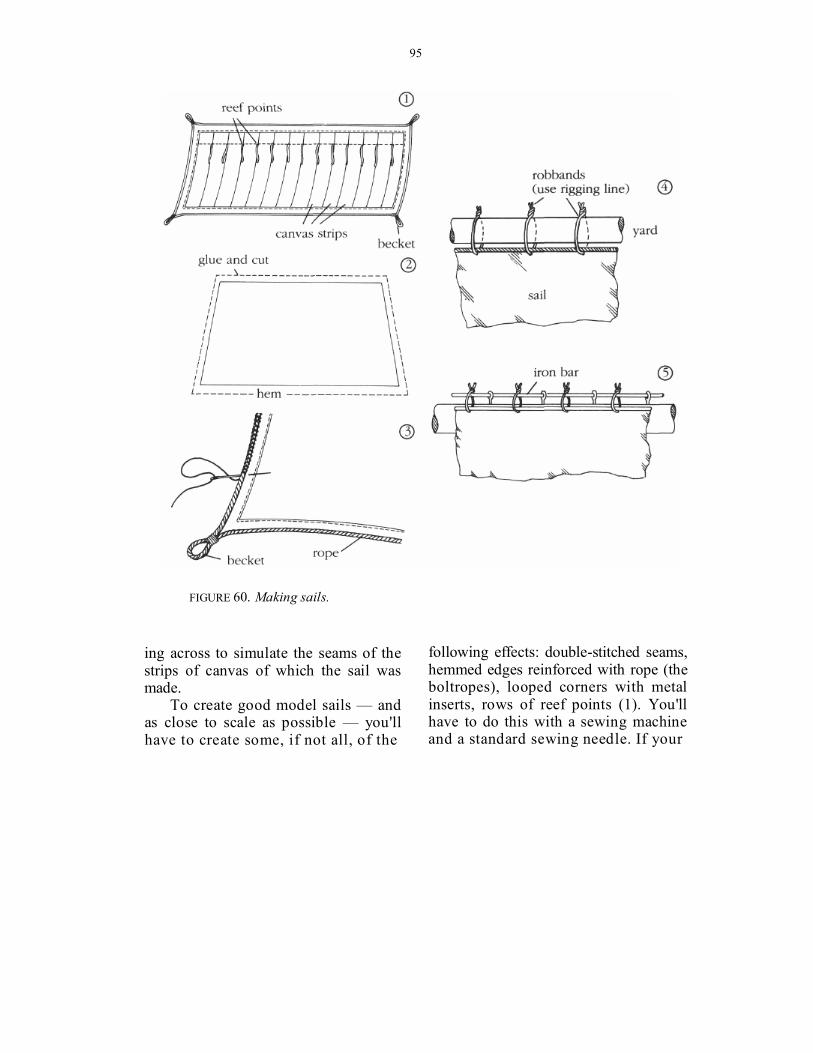
Consider Figure 60. Some kits in-clude sheets of material for the sails — some trace the contour of the sails on the fabric while others print the stitch-
95
FIGURE 60. Making sails.
ing across to simulate the seams of the strips of canvas of which the sail was made.
To create good model sails — and as close to scale as possible — you'll have to create some, if not all, of the
following effects: double-stitched seams, hemmed edges reinforced with rope (the boltropes), looped corners with metal inserts, rows of reef points (1). You'll have to do this with a sewing machine and a standard sewing needle. If your
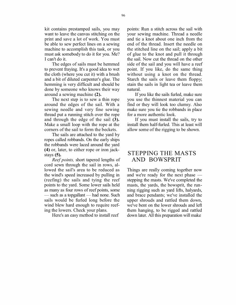
96
kit contains prestamped sails, you may want to leave the canvas stitching on the print and save a lot of work. You must be able to sew perfect lines on a sewing machine to accomplish this task, or you must ask somebody to do it for you. Me? I can't do it.
The edges of sails must be hemmed to prevent fraying. It's a good idea to wet the cloth (where you cut it) with a brush and a bit of diluted carpenter's glue. The hemming is very difficult and should be done by someone who knows their way around a sewing machine (2).
The next step is to sew a thin rope around the edges of the sail. With a sewing needle and very fine sewing thread put a running stitch over the rope and through the edge of the sail (3). Make a small loop with the rope at the corners of the sail to form the beckets.
The sails are attached to the yard by ropes called robbands. On the early ships the robbands were laced around the yard (4) or, later, to either rope or iron jack-stays (5).
Reef points, short tapered lengths of cord sewn through the sail in rows, al-lowed the sail's area to be reduced as the wind's speed increased by pulling in (reefing) the sails and tying the reef points to the yard. Some lower sails held as many as four rows of reef points, some — such as a topgallant — had none. Such sails would be furled long before the wind blew hard enough to require reef-ing the lowers. Check your plans.
Here's an easy method to install reef
points: Run a stitch across the sail with your sewing machine. Thread a needle and tie a knot about one inch from the end of the thread. Insert the needle on the stitched line on the sail; apply a bit of glue to the knot and pull it through the sail. Now cut the thread on the other side of the sail and you will have a reef point. If you like, do the same thing without using a knot on the thread. Starch the sails or leave them floppy; stain the sails in light tea or leave them natural.
If you like the sails furled, make sure you use the thinnest material you can find or they will look too clumsy. Also make sure you tie the robbands in place for a more authentic look.
If you must install the sails, try to install them half-furled. This at least will allow some of the rigging to be shown.
STEPPING THE MASTS AND BOWSPRIT
Things are really coming together now and we're ready for the next phase — stepping the masts. We've completed the masts, the yards, the bowsprit, the run-ning rigging such as yard lifts, halyards, and brace pendants; we've installed the upper shrouds and rattled them down, we've bent on the lower shrouds and left them hanging, to be rigged and rattled down later. All this preparation will make
97
98
it a lot easier to belay everything to the hull because you won't be working in tight and awkward positions.
As we talked about earlier in Part III (seems like a long time ago doesn't it?), I reduce the part of the masts that will be inserted through the holes in the deck (to 1/4-inch or 6 mm diameter) when making the lower masts. This makes it easier to drill the holes in the deck and reduces the chance of splintering the deck planking.
The most important part of this in-stallation is to make sure that the mast assemblies are set square athwartships and raked to the proper angles fore and aft. The rake of each mast is always indicated in your plans.
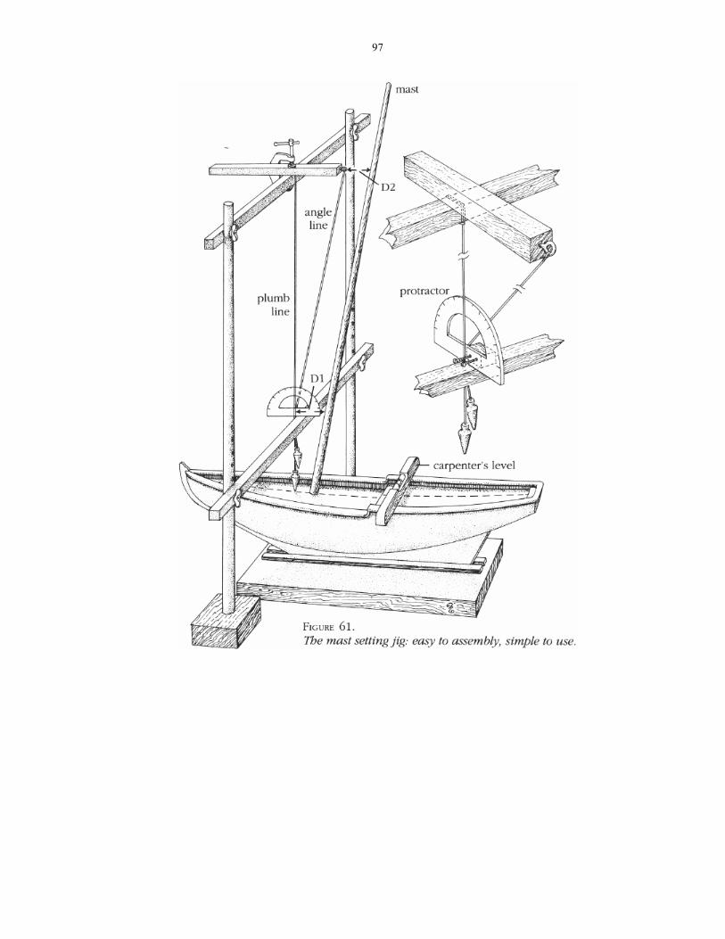
MAST STEPPING JIG
To do this properly I've developed a simple jig that's very easy to build. Take a look at Figure 61. Basically the assem-bly is not unlike a football goalpost, only with two crossbars and a few other dif-ferences. You'll be able to slip your hull underneath and set the rake of your masts with ease.
For the base, cut two 6-inch pieces from a 2 X 4 and drill 1/2-inch holes in the middle of each block. For the up-rights, use 1/2-inch dowels about two feet long. You'll need six holes in each, about a half-inch apart. Place the uprights side by side on the workbench with ends flush, mark where the holes will sit, then put them in a vise and drill them. Be
careful here. The holes should be at identical heights in each upright, and be wide enough to fit a 1/8-inch machine bolt. Insert the uprights in the 1/2-inch holes in the 2X4 blocks. The jig needs one crossbar that you can move up and down to accommodate various heights of models.
For the movable crossbar, we'll use a 3/4-inch by 3/4-inch square piece of pine, about a foot long. Drill a hole in each end of the bar, leaving a half-inch or so at each end. Do the same for the upper crossbar. Now connect the lower and upper crossbars with the uprights.
Next, take a third 3/4-inch square strip of pine, about a foot or so long, and screw in an eyebolt (or drive in a nail) in one end. Clamp this strip at right angles to the upper crossbar; we'll be adjusting it later. Let's call this the gal-lows beam.
Next grab a protractor, some black thread, and a sinker from your fishing gear.
Here's how it works: Tie the sinker on the end of the thread and wrap the thread around the middle of the upper crossbar. Secure it temporarily with a simple knot so you can adjust it later; this will be your plumb line. Tie a sec-ond line on the eyebolt at the end of the gallows beam. Set your model on a flat surface (the keel board, preferably) and put a carpenter's level across the bul-warks. Level your model and set it aside for the moment; set the lower crossbar so that it's about 4 inches higher than

99
the model. Set the protractor on the lower crossbar next to the plumb line so that the vertical zero line is exactly in line with the plumb line.
Glue a small block of wood to the protractor and use a clothespin to hold the protractor assembly in place on the lower crossbar. Adjust the gallows beam so that it's directly above the eyebolt holding the plumb line. This will repre-sent a mast at 90 degrees. Next, take the string on the end of the gallows beam and set it on the lower crossbar at the same point where the plumb line crosses the lower crossbar. The two strings should meet at the centerline on the protractor.
As you slide the gallows beam for-ward or backward, the string on its end will move along the arc of the protrac-tor. Get the angle of rake from your plans, slide the gallows beam until the string matches that angle on the protrac-tor, and clamp it down.
Here's another tip before we get started: If you set the mizzenmast first, the mainmast second, and the foremast last, it will be easier to remove the jig from the model. Let's get started.
STEPPING THE MAST. Remove the pro-tractor. Straddle the model with the jig so that the sinker on the end of the plumb line is centered in front of the mast hole. Insert the mast in the hole and align it with the plumb line, looking from aft of the model. Next, move to the side of the model and adjust the mast to match
the angle we just set with the second string.
"How do you do that?" you ask. The distance (Dl) from the mast to the point where the two lines rest against the lower crossbar should be equal to the distance (D2) from the knot on the eyebolt on the upper strip to the mast. After you've made a dry run, dab some glue on the bottom of the mast and insert it at the proper angle.
To keep the mast from moving while the glue dries, take a lower shroud from each side, wrap it around a deadeye on the channels and hold it with an alliga-tor clip. Make sure the masttop is paral-lel to the deck. If you do the job right all masts will be in line with each other athwartships because they'll be in line with the plumb line. Of course, every mast will have a different angle of rake, so you have to reset the line each time you set a mast.
The jig can be dismantled for stor-age.
STEPPING THE BOWSPRIT. After all the masts are in place, step the bowsprit. Most kits have predrilled holes in the stem of the hull through which to fit the bowsprit. You may have to file it slightly for a better fit. Your plans will indicate the distance from the baseline to the tip of the bowsprit; this will assure that the vertical angle (the sleeve) of the bowsprit is correct. Apply a dab of glue to the base of the bowsprit and slide it in place, making sure that its steeve is correct. To

100
check that its square athwartships, sight down the bowsprit from the front of the model at the masts. Apply a dab of ACC and let it set.
RIGGING IT ALL TO THE HULL
GETTING READY
Now that all the spars are fitted and rigged — and the masts and bowsprit stepped — we're ready to attach every-thing to the hull. How? Some lines will be belayed to pins, some will be bent to deadeyes, some will be seized (with our simple method, for now).
Rigging is an often delicate, some-times annoying, and always rewarding task — if it's done right. Here are some tips that will save you a great deal of nail biting.
The key words when rigging are symmetry and balance. If you pull on one side, remember to counter it with an opposing pull. Before you start rigging on one side of the model, it's a good idea to tie a shroud temporarily to the deadeye on the other side. This will prevent the mast from bending while you are snugging up on the deadeye rigging and give you better looking, tighter shrouds.
Let's review the order in which eve-rything will be rigged to the hull:
Step 1: Belay the yard lifts and halyards to their respective pins. Do not in-stall yard braces at this time.
Step 2: Bend standing rigging in the fol-lowing sequence: bowsprit bobstays, foremast stays to the bowsprit; all the mizzenmast gaffs and boom rigging; mainmast center stays to the fore-mast; and finally, the mizzenmast center stays to the mainmast.
Step 3: Rig all lower shrouds to their lanyards.
Step 4: Bend the backstays on each mast; the sequence doesn't matter.
Step 5: Install boats and davits, if called for.
Step 6: Fit and belay all yard braces.
AN EASY WAY. Much of the standing rigging is secured to lower deadeyes with lanyards. On real ships, the lanyard hauled taut the shrouds and kept them taut. That meant tying a stopper knot in the lanyard end and reeving it through alternate eyes, starting with the upper deadeye. After hauling taut, the end of the lanyard was run under itself to form a half hitch then wound around the stay or shroud. It was an effort that called more for muscle than finesse. Not so on a model.
Before we get started we should think about what we're doing. Just how do you attach a rope to a deadeye, in scale? Look at Figure 63 on page 102.
To make sure that the lanyards se-curing the shrouds are all the same length, we're going to make a "deadeye
!

101
gauge" from a piece of pliable steel wire (1). Bend the wire at right angles at each end — long enough to fit into and hold the upper and lower deadeyes that will be held by the lanyard. The straight part of the gauge should be about three times the diameter of the deadeyes.
For our purposes, attach the shrouds to the deadeyes beginning with the fore-mast, alternating port and starboard. Insert one end of the deadeye gauge in the middle hole of the upper deadeye and the other end into the middle hole of the lower deadeye (2). Hold this in place with your left hand (if you're righthanded) and with your right, wrap the lower part of the shroud around the upper deadeye. Put tension on the shroud end while pulling upward. Move your left fingers up to catch and hold the two lines, and with your right hand use an alligator clip to hold them together.
Take a fine black rigging line and tie a double overhand knot around the shroud right above the upper deadeye. Apply a drop of glue to the knot and wrap the fine line around the shroud to seize it, ending with a clove hitch.
Here's how to reeve the lanyards through the deadeyes now held by the gauge. At the foremast, beginning on the port side, tie a double knot on the end of a fine black line and start threading
FIGURE 62. Channels and deadeyes: where a lot of line meets a little space. Rigging through deadeyes is not as hard as it may appear.

102
FIGURE 63. Rigging shrouds the easy way.
on the left hole of the upper deadeye and toward you. Next go through the left hole of the lower deadeye away from you (3). At this point, remove the deadeye gauge and continue on through the rest of the holes (4). Now pull down on the shroud with your left hand while pulling the lanyard up with your right hand to obtain the tension needed. Once this is accomplished and the deadeyes are set, tie the end of your lanyard around the shroud above the upper deadeye. Trim the excess line; apply a little glue and let dry.
Now that you've got that trick down (you may want to practice before trying it on your model), we're ready to actu-ally start rigging everything. Here are some other things to keep in mind.
Never: • cross rigging lines with each other • run rigging lines on the forward side
of the yards • bend rigging lines around obstacles • run rigging lines through ratlines • make knots on rigging lines
STAYS
Place your hull (no need to remove it from its base) on a revolving stand. This will help immensely in turning the model around to reach for the belaying pins on the port or starboard side. Your best bet is a turntable from an old stereo system or a lazy Susan from the dinner table.
103
SIMPLIFYING YOUR WORK
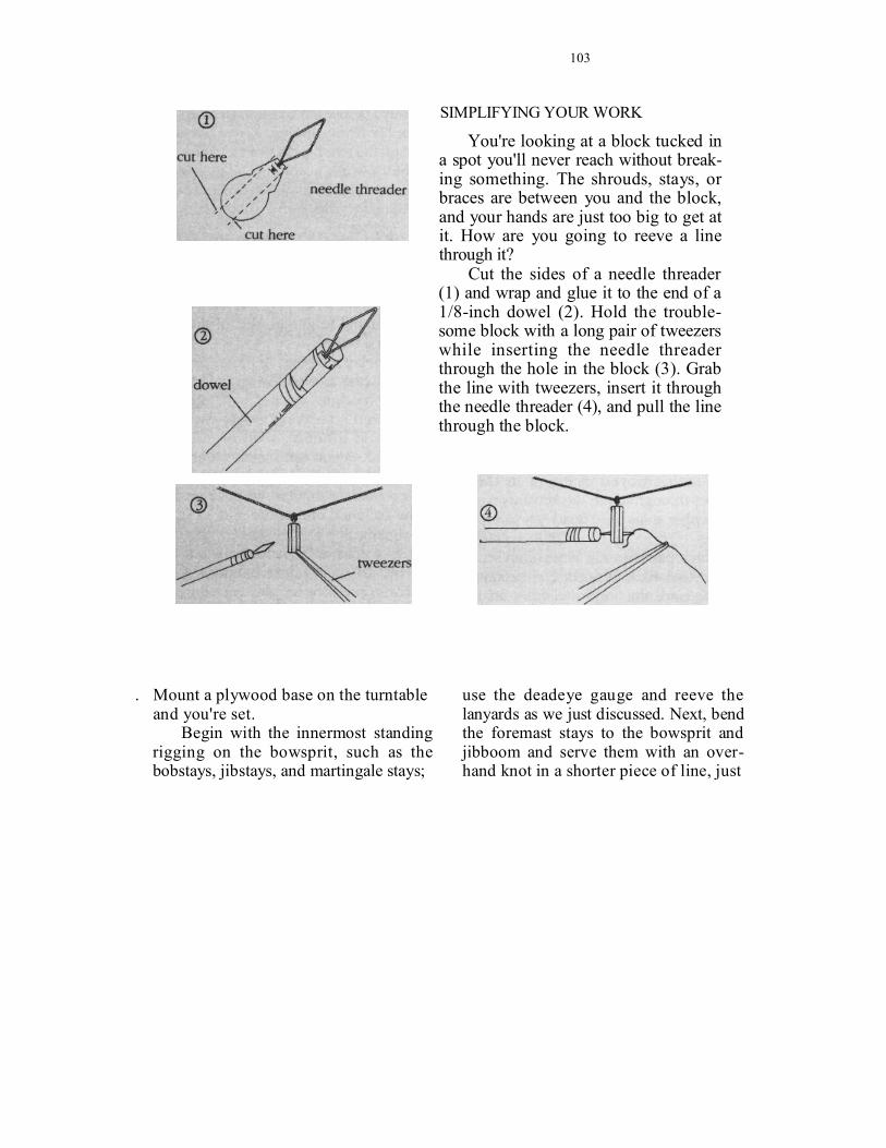
You're looking at a block tucked in a spot you'll never reach without break-ing something. The shrouds, stays, or braces are between you and the block, and your hands are just too big to get at it. How are you going to reeve a line through it?
Cut the sides of a needle threader (1) and wrap and glue it to the end of a 1/8-inch dowel (2). Hold the trouble-some block with a long pair of tweezers while inserting the needle threader through the hole in the block (3). Grab the line with tweezers, insert it through the needle threader (4), and pull the line through the block.
. Mount a plywood base on the turntable and you're set.
Begin with the innermost standing rigging on the bowsprit, such as the bobstays, jibstays, and martingale stays;
use the deadeye gauge and reeve the lanyards as we just discussed. Next, bend the foremast stays to the bowsprit and jibboom and serve them with an over-hand knot in a shorter piece of line, just

104
as we did earlier with the shrouds. Do not glue any knots or cut the excess line until everything is finished. This will enable you to readjust the stays' tension when all the rigging is finished.
After we bend and seize the foremast stays to the bowsprit, we'll secure the boom sheets and the gaff vangs to their belaying pins. This will set the proper aft tension on the mizzenmast so that it will not bend forward when we install the stays. Next rig the mainmast stays (on some ships, a mast could have as many as five stays) to the foremast, and the mizzenmast stays to the mainmast. Since no other rigging is in the way yet, it will be easier at this time to rig the lower stays to the blocks on deck.
On some ships the lower stays were rigged with hearts — sometimes heart-shaped, often round wooden blocks about the same size as deadeyes with a large multigrooved opening in their middles through which the lanyards were rove. Other ships used deadeyes or triple blocks.
Stays, like shrouds, were often set in pairs. And, like shrouds, the secret is making sure the stays are even at the deck. Here's a quick way to install your lower stays. Check the plans for the length of your stay and cut some black thread double that amount. Bend one end of the line around a block as dic-tated by the plans. Run the stay through the holes in the masttop, around the mast, and back down to the first block, where you'll bend the free end around
a second block. Put an alligator clip on the stays below the masttop to keep the assembly from slipping. Reeve lanyards through the two blocks to attach the stays to the bulwark according to the plans. Seize the two stays together above the alligator clip, serve them, and the stays are set.
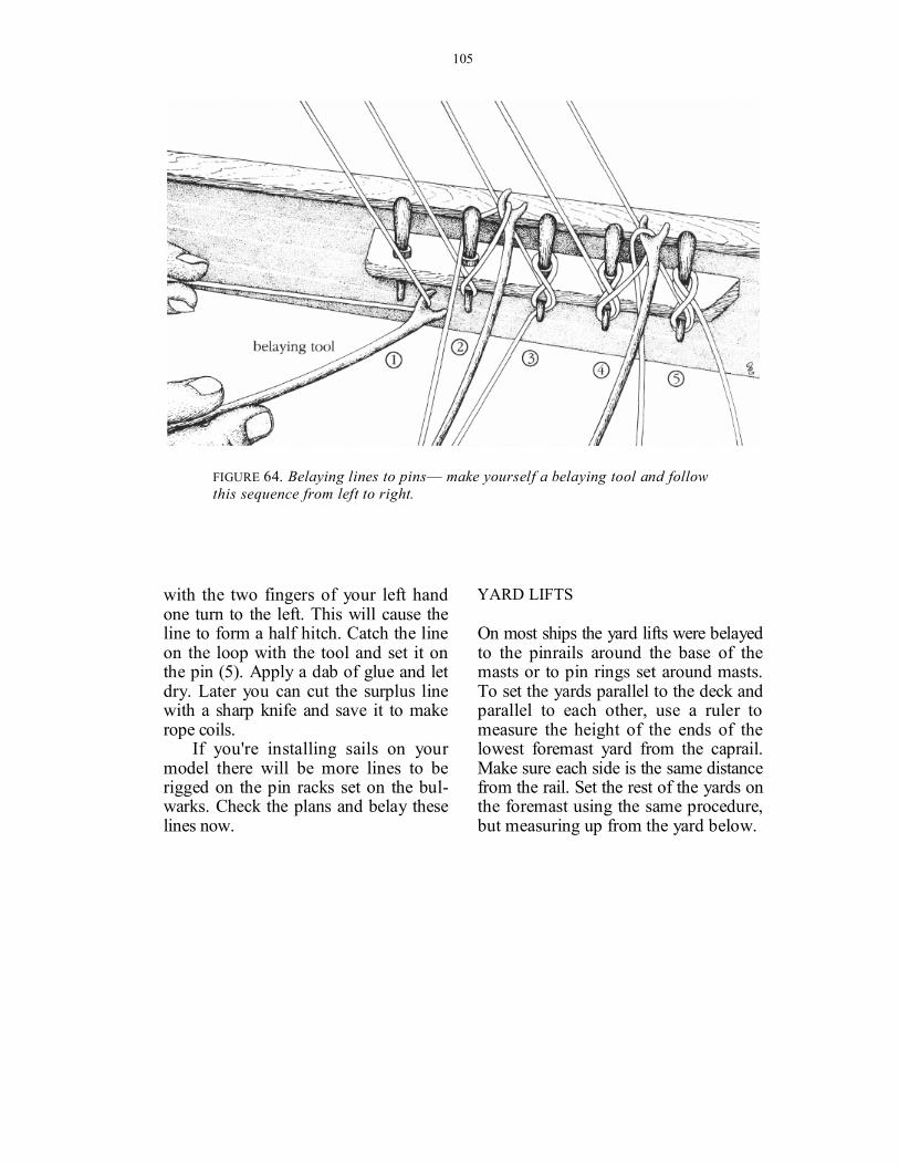
BELAYING LINES
Most kits have a belaying pin plan. Study it beforehand to get an idea of the pat-tern you'll follow.
To belay a rigging line to a pin you wrap the line around the pin in a figure eight fashion, as we see in Figure 64. You'll need a belaying tool — you can buy one at a hobby shop or you can make one. If you opt for the latter, find a stiff wire, such as a wire clothes hanger. Heat the tip of the wire over a flame and flatten it with a hammer on a steel plate. With a small triangular file cut a groove at the flattened end of the wire to catch the rigging line (1). Make sure that this part is not too wide and the groove is not too deep, otherwise you will be unable to insert the tool between the pins and wrap the line around them.
Hold the end of the line with your left hand (assuming you're righthanded) and with your right hand press the be-laying tool to the line. Push the line under and around the pin (2). Next turn the line across and around the pin above the rack, forming a figure eight (3). Repeat two or three times (4). Now twist the line
105
FIGURE 64. Belaying lines to pins— make yourself a belaying tool and follow this sequence from left to right.
with the two fingers of your left hand one turn to the left. This will cause the line to form a half hitch. Catch the line on the loop with the tool and set it on the pin (5). Apply a dab of glue and let dry. Later you can cut the surplus line with a sharp knife and save it to make rope coils.
If you're installing sails on your model there will be more lines to be rigged on the pin racks set on the bul-warks. Check the plans and belay these lines now.
YARD LIFTS
On most ships the yard lifts were belayed to the pinrails around the base of the masts or to pin rings set around masts. To set the yards parallel to the deck and parallel to each other, use a ruler to measure the height of the ends of the lowest foremast yard from the caprail. Make sure each side is the same distance from the rail. Set the rest of the yards on the foremast using the same procedure, but measuring up from the yard below.
106
The mainmast and mizzenmast yards will be leveled, by sighting, to the foremast yards.
HALYARDS
Next come the halyards. Most halyards end with a purchase tied between two or more blocks and belayed to the bul-warks' pinrails or to rings on the deck.
LOWER SHROUDS
Now that the lifts, the halyards, the sails (if any), and their rigging are secured, we can work on the lower shrouds.
Rig the shrouds just as we discussed earlier in this section — using the deadeye gauge and the alligator clip. Use black line for the shrouds (they were tarred) and the lanyards. Lash sheerpoles above the deadeyes if your model calls for them.
BACKSTAYS
The backstays are tied down next. Fol-low the same method we used for the lower stays. Be careful not to pull so hard on the stays that you bend the mast side-ways or backward.
YARD BRACES AND SAIL SHEETS
The yard braces and sail sheets are last. Belay the braces and sheets starting at the top of the foremast, moving down the mast. When the braces and sheets
on the foremast are belayed, move to the top of the mainmast and work down again. Then move on to the mizzenmast.
Rigging the braces between the main and mizzen is a bit challenging because the lines will cross. Take great pains to prevent them from bending and rubbing against each other. The easiest way is to alternate by rigging the braces of one yard to the main and one yard to the mizzen, checking that the lines do not rub or bend against each other.
While you're doing this you'll notice that it is very hard to reach the double blocks attached to the masts. You can use a long tweezer and a needle threader glued to the end of a dowel as we dis-cussed.
When sails weren't attached, as in port, the yards usually were braced squarely. If you want your model to appear under sail, take great care when rigging the braces to set the angles of the yards. Yards were never braced at the same angle because the sails on one mast would move the apparent wind farther forward on the next mast aft. In fact, even sails on the same mast were not braced the same; the apparent wind moves aft as you go aloft, so that upper sails need not be braced as far around as the lowers.
If you decided not to use sails, set the highest yard on the foremast at the angle you prefer. (Sometimes a little bend to port or starboard makes the model look more interesting.) Set the rest of the yards on the foremast parallel or nearly

107
PHOTO 25. A well-executed row of rope coils on the pin rails.
so to the top yard by sighting from above. The angle of the yards on the main and mizzen will be more radical; the yards on individual masts, however, will be close to the same angle.
Do not belay the braces on the lower yards at this time if your model carries boats or davits. The davits and the boats
must be installed before the lower yard braces.
The final touch to your rigging is to install rope coils on the belaying pins. After you make the rope coils (see page 67), install them using a long tweezer and a dab of glue.