part number sp1576 2002-05 honda civic si - … number sp1576 2002-05 honda civic si ... illustrated...
TRANSCRIPT

Part number SP15762002-05 Honda Civic Si
1- One piece Cold air intake1- 3” Injen filter (#1014)1- 60 deg. 2 7/8” x 3” (#3007)
Silicone elbow1- 1525 sensor grommet (#6014)2- Power-band .362 .048 (#4004)1- M6 Vibra-mount (#6020)1- fender washer (#6010)1- 6mm flange nut (#6002)2- Mini hose clamp .010 (#4007)1- 20” 8mm vac. hose (#3091)1- 18” 17mm vac hose (#3080)1- 5 page Instruction
Note: The installation of this cold air intake does require mechanical skills. Removal of the front bumper requiresloosening and removing several plastic plugs and screws that may be difficult. It is recommended that thissystem be installed by a professional mechanic. Removal of the battery and battery tray bracket is also removed by the use of an electric drill.
Warning: Install this intake while in 5th gear so that the shifter lever is at its furthest point in order to have plenty ofclearance between the intake and the shifter lever.
Hydro-shield used with this applicationX-1033

The diagram will help aid in the removal of the frontbumper. Illustrated above is an Acura RSX but the clipsand screws will be the same as the Honda Civic Si.

Remove the remainder of the thermalvalve bypass control hose from theintake port.
Cut an opening in the plastic splash guard as shown in the picture above. Theside top portion has two sides that will require cutting in order to insert the cold airintake. Enlarge the opening as needed by fitting the filter end of the intake intothe opening.
Using a 10mm socket or nut driverremove the ground wire bolt from itsstock location.
Take the 6mm vibra-mount and placeit in the location where the groundingwire was originally removed from.
Remove the stock battery tie down and remove the cables from the battery.When safe to do so, remove the battery from the engine compartment and placeit on a table or cardboard.
Once the battery has been removed youwill need a drill and a 3/8” drill bit to drillthree hose on the spot welds that holdsthe bracket in place
Remove the two bolts that secure the engine cover. Use a pair of pliers todepress the hosel clamp at the crankcase(A). Now depress the clamp on the airtemperature sensor and remove it from the stock intake tube, do the same forthe thermal valve vent hose(B). Remove the five bolts that secure the air intakebox and pull the box up and away from the engine compartment.
Use a 10mm socket to loosen the bolt that secures the stock air inlet duct asshown in this picture.
Use the drill and 3/8 drill bit as shownto knock out the spot welds on the bat-tery tray. Remove the bracket from thebattery tray as shown above (A).
Take the assembled grounding wireand bolt and place it in its new locationas shown above.
Take the 65 degree silicone elbow andplace the 2 7/8” side over the throttlebody. Place two .362 bands on each endof the elbow but do not tighten yet.
(A) (B)
(B)
(A)<<
<<
Remove the short stock hose (A) thatconnected the crankcase port to the airbox as shown in this picture.
(A)

Locate the air temperature sensor andpress it into the 1525 sensor grommet.
Take the 18” 17mm vacuum hose and press one end over the 3/4” intake port (A).Press the other end over the crankcase port (B), use the small clamps in this kitto secure the hose at the crankcase and the intake port.
Take the filter and press the filter neck over the end of the intake. Use theclamp on the filter neck to secure the filter to the intake.
Once the intake has been aligned for best possible fit have a second person shiftthrough all the gears to make sure that the intake does not obstruct the shifting inanyway. If the lever does not hit the intake continue with the installation of theintake.
In 5th gear, the shift lever link should be facing the intake. Adjust the intake sothat it is away and free from hitting the lever (A). Press the upper portion of the intake into the elbow with the clamp.
While the upper end has been inserted into the silicone elbow, align the intakebracket to the vibra-mount stud (A). Use the m6 flange nut and fender washer tosecure the intake in place. The filter end of the intake should be positioned asshown in the picture above(B).
Take the 1525 sensor grommet and press it into the pre-drilled 3/4” hole asshown in (A). Insert the grommet into the hole until grommet is well seatedthroughout the hole circumference.
Install the upper portion of the intake through the bumper opening. Bring it upinto the engine compartment and into the throttle body elbow.
(A)
(A)
(A)
(B)
Take the 20” 8mm vacuum line andpress one end into the 3/8 port on theintake (A), press the other end over thethermal valve bypass port(B).
<<<<
(A)
(B)(B)
(A)
1. Once the installation is complete, reconnect the negative battery terminal before you start the engine.
2. Align the entire intake system for the best possible fit. Once the intake has been properly fitted continueto tighten all nuts, bolts and clamps.
3. Periodically, recheck the alignment of the intake system and make sure there is proper clearance aroundand along the length of the intake. Failure to follow proper maintenance procedures may causedamage to the intake and will void the warranty.
4. Start the engine and listen carefully for any odd noises, rattles and/or air leaks prior to taking it for a testdrive. If any problems arise go back and check the vacuum lines, hoses and clamps that maybe causingleaks or rattles and correct the problem.
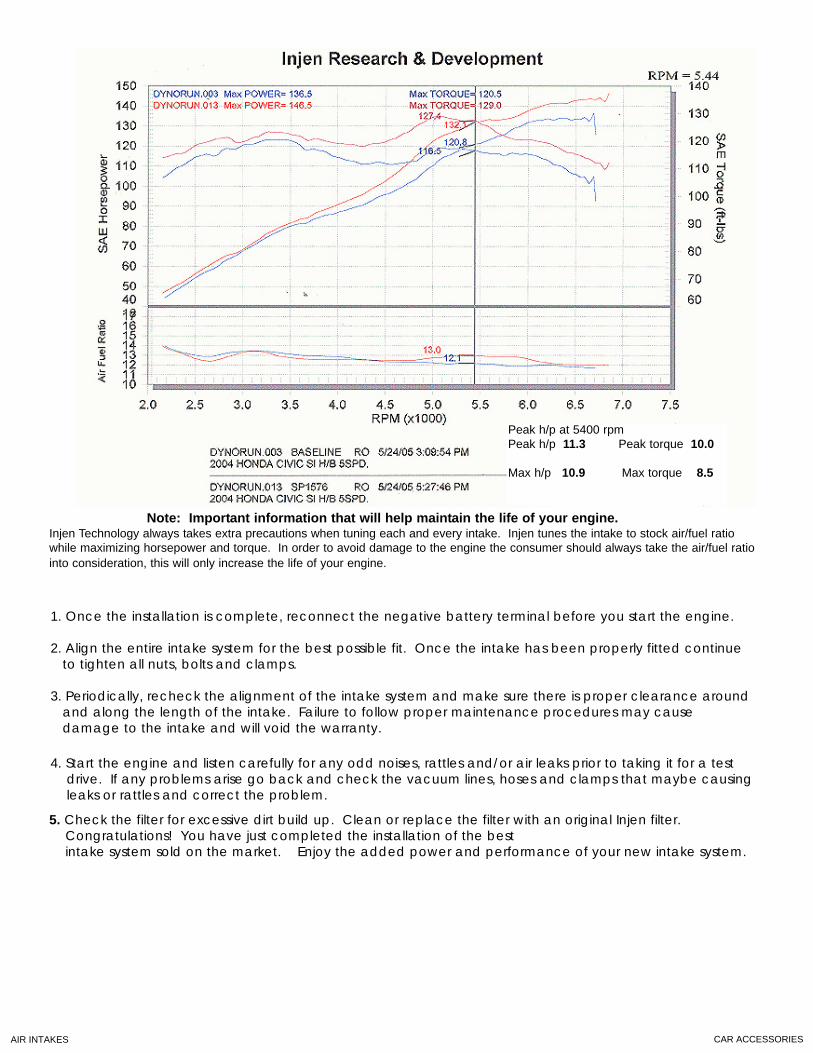
Peak h/p at 5400 rpmPeak h/p 11.3 Peak torque 10.0
Max h/p 10.9 Max torque 8.5
Note: Important information that will help maintain the life of your engine.Injen Technology always takes extra precautions when tuning each and every intake. Injen tunes the intake to stock air/fuel ratiowhile maximizing horsepower and torque. In order to avoid damage to the engine the consumer should always take the air/fuel ratiointo consideration, this will only increase the life of your engine.
5. Check the filter for excessive dirt build up. Clean or replace the filter with an original Injen filter.Congratulations! You have just completed the installation of the best intake system sold on the market. Enjoy the added power and performance of your new intake system.
AIR INTAKES CAR ACCESSORIES