part replacement drive belts
TRANSCRIPT

Part Replacement
STAIRMASTER 1 of 9 637-1568 Rev: A
Drive Belts
Air Fit (160002)
Parts Required:
• Crank to Transmission Belt (PN: 130-1812)
• Transmission to Fan Belt (PN: 130-1814)
Tools Required:
• Screwdriver Set or Specific Drivers o Phillips Head Screwdriver
• Metric Hex Key Wrench Set or Specific Keys o 4mm Hex Key o 5mm Hex Key
• Metric Open End Wrench Set or Specific Wrenches o 13mm Open Wrench o 10mm Open Wrench o 16mm Open Wrench
Instructions:
1. Remove the crank ring shroud (Fig. 1) from the left & right large base shrouds by extracting the lone phillips head screws that hold each ring in place with a phillips head screwdriver and then turn each of the rings clock-wise to unlock and pull off.
Fig. 1

Part Replacement
STAIRMASTER 2 of 9 637-1568 Rev: A
2. Detach the left & right crank linkage arms from the crank cams by removing the two securing shoulder bolts
(Fig. 2) from each of the crank cams using a 4mm hex key and pull the linkage arm away from the crank cam bracket.
NOTE:
Do not remove the user right link arm if only replacing the transmission to fan belt!
Fig. 2
3. Maneuver the arms and linkages (Fig. 3) in a scissor motion that will move the link arms away from the pedals
and provide non-obstructed access to the large side shrouds.
Fig. 3
Part Replacement
STAIRMASTER 3 of 9 637-1568 Rev: A
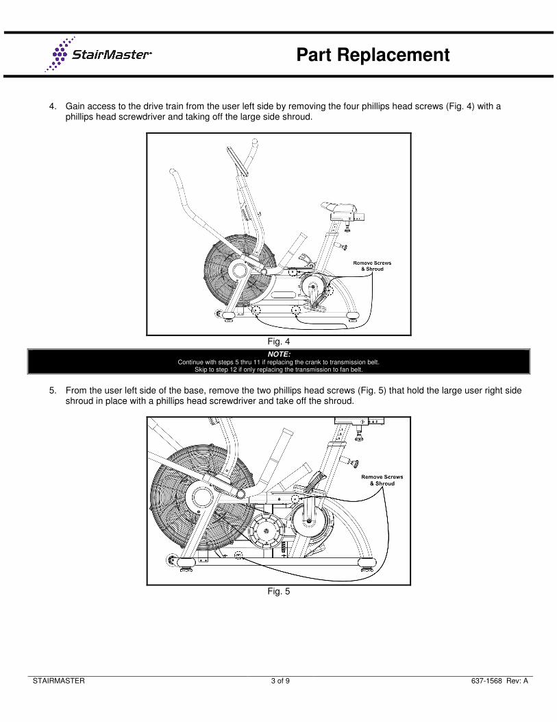
4. Gain access to the drive train from the user left side by removing the four phillips head screws (Fig. 4) with a
phillips head screwdriver and taking off the large side shroud.
Fig. 4
NOTE:
Continue with steps 5 thru 11 if replacing the crank to transmission belt. Skip to step 12 if only replacing the transmission to fan belt.
5. From the user left side of the base, remove the two phillips head screws (Fig. 5) that hold the large user right side
shroud in place with a phillips head screwdriver and take off the shroud.
Fig. 5

Part Replacement
STAIRMASTER 4 of 9 637-1568 Rev: A
6. Remove the idler tension spring, screw, and corresponding hardware (Fig. 6) by loosening the jam nut at the
bottom of the screw and the jam nut butted to the idler block using a 13mm open end wrench.
Fig. 6
7. From the user left side remove the clutch assisted idler wheel assembly (Fig. 7) from the base by loosening the
locking nut with a 16mm open wrench and then sliding off the idler assembly and washers.
Fig. 7

Part Replacement
STAIRMASTER 5 of 9 637-1568 Rev: A
8. From the user right side; maneuver the belt (Fig. 8) off the crank and transmission pulleys.
Fig. 8
9. To install a new crank to transmission belt; reverse steps 8-6 before moving forward to step 10.
10. Verify proper tension is applied to the belt by adjusting the idler assembly to compress the die spring
between 55-58 mm (Fig. 9) from end to end.
Fig. 9
11. Reverse steps 5-1 to complete installation of the crank to transmission belt or continue to step 12 if replacing the
transmission to fan belt.

Part Replacement
STAIRMASTER 6 of 9 637-1568 Rev: A
12. Take off the left & right shrouds covering the center point of the fans axle by removing the two securing screws
(Fig. 10) using a 4mm hex key.
Fig. 10
13. Loosen the axle jam nut on the left & right sides of the fan to relieve stress on the axle alignment eyebolt (Fig. 11)
and dislodge the RPM sensor from the wedge channel of the axle bracket.
Fig. 11

Part Replacement
STAIRMASTER 7 of 9 637-1568 Rev: A
14. Remove the eyebolt axle alignment bracket (Fig. 12) by loosening the securing jam nut with a 10mm open
wrench.
Fig. 12
15. Drive the transmission to fan belt (Fig. 13) off the large transmission pulley near the center of the base.
Fig. 13

Part Replacement
STAIRMASTER 8 of 9 637-1568 Rev: A
16. Now remove the securing button head screw with washer (Fig. 14) from the center fan cage bracket on both left
and right sides of the unit using a 4mm hex key.
Fig. 14
17. Remove the securing phillips head screws (Fig. 15) from the left & right lower fan cage brackets.
Fig. 15

Part Replacement
STAIRMASTER 9 of 9 637-1568 Rev: A
18. Pull the fan and cage assembly off the machines base (Fig. 16) and maneuver the belt off the axle pulley and out
off the fan cage.
Fig. 16
19. To install a new transmission to fan belt; reverse steps 18-14.
20. Verify fan alignment and belt tension by adjusting the jam nuts on the left & right side eye bolts (Fig. 17). Tension
should allow for a 90° twist of the belt (Fig. 18) at the center of the fan & transmission pulleys.
Fig. 17
Fig. 18
21. Reverse steps 13-1 to conclude installation.