partial transmit sequence based low complexity receiver ...ethesis.nitrkl.ac.in/6173/1/e-39.pdf ·...
TRANSCRIPT

Partial Transmit Sequence BASED loW
complexity receiver for multi-user
stbc mc-cdma system
A Thesis submitted in partial fulfillment of the Requirements for the degree of
Master of Technology
In
Electronics and Communication Engineering
Specialization: Communication and Networks
By
Sadananda behera
Roll No. : 212EC5168
Department of Electronics and Communication Engineering
National Institute of Technology Rourkela
Rourkela, Odisha, 769 008, India
May 2014

Partial Transmit Sequence BASED low
complexity receiver for multi-user
stbc mc-cdma system
A Thesis submitted in partial fulfillment of the Requirements for the degree of
Master of Technology In
Electronics and Communication Engineering
Specialization: Communication and Networks
By
Sadananda Behera
Roll No. : 212EC5168
Under the Guidance of
Prof. Sarat K. Patra
Department of Electronics and Communication Engineering
National Institute of Technology Rourkela
Rourkela, Odisha, 769 008, India
May 2014

Dedicated to…,
My parents and my elder brother.

DEPT. OF ELECTRONICS AND COMMUNICATION
ENGINEERING
NATIONAL INSTITUTE OF TECHNOLOGY, ROURKELA
ROURKELA – 769008, ODISHA, INDIA
Certificate
This is to certify that the work in the thesis entitled Partial Transmit Sequence based low
complexity receiver for multi-user STBC MC-CDMA system by Sadananda Behera is
a record of an original research work carried out by him during 2013 - 2014 under my
supervision and guidance in partial fulfillment of the requirements for the award of the
degree of Master of Technology in Electronics and Communication Engineering
(Communication and Networks), National Institute of Technology, Rourkela. Neither this
thesis nor any part of it, to the best of my knowledge, has been submitted for any degree or
diploma elsewhere.
Place: NIT Rourkela Dr. Sarat Kumar Patra
Date: 25th May 2014 Professor

DEPT. OF ELECTRONICS AND COMMUNICATION
ENGINEERING
NATIONAL INSTITUTE OF TECHNOLOGY, ROURKELA
ROURKELA – 769008, ODISHA, INDIA
Declaration I certify that
a) The work contained in the thesis is original and has been done by myself under the
general supervision of my supervisor.
b) The work has not been submitted to any other Institute for any degree or diploma.
c) I have followed the guidelines provided by the Institute in writing the thesis.
d) Whenever I have used materials (data, theoretical analysis, and text) from other
sources, I have given due credit to them by citing them in the text of the thesis and
giving their details in the references.
e) Whenever I have quoted written materials from other sources, I have put them
under quotation marks and given due credit to the sources by citing them and giving
required details in the references.
Sadananda Behera
25th May 2014

i
ACKNOWLEDGEMENTS
It is my immense pleasure to avail this opportunity to express my gratitude, regards and
heartfelt respect to Prof. Sarat K. Patra, Department of Electronics and Communication
Engineering, NIT Rourkela for his endless and valuable guidance prior to, during and
beyond the tenure of the project work. His priceless advices have always lighted up my
path whenever I have struck a dead end in my work. It has been a rewarding experience
working under his supervision as he has always delivered the correct proportion of
appreciation and criticism to help me excel in my field of research.
I would like to express my gratitude and respect to Prof. P. Singh, Prof. S. Maiti and
Prof. S. Hiremath for their support, feedback and guidance throughout my M. Tech course
duration. I would also like to thank all the faculty and staff of ECE department, NIT
Rourkela for their support and help during the two years of my student life in the
department.
I would like to make a special mention of the selfless support and guidance I received
from my senior Prasanta Kumar Pradhan and Amiya Singh, Department of Electronics and
Communication Engineering, NIT Rourkela during my project work. Also I would like to
thank Khushboo Mawatwal and Seemanjali Sahoo for making my hours of work in the
laboratory enjoyable with their endless companionship and help as well; along with all
other friends like Manas Ranjan Biswal, Satyendra Singh Yadav, Sangeeta Bhattacharjee,
and many more who made my life in NIT Rourkela a memorable experience all together.
Last but not the least; I would like to express my love, respect and gratitude to my
parents and my elder brother Dr. Samarendra Behera, who have always supported me in
every decision I have made, guided me in every turn of my life, believed in me and my

ii
potential and without whom I would have never been able to achieve whatsoever I could
have till date.
Sadananda behera

iii
ABSTRACT
Space Time Block Code Multi Carrier Code Division Multiple Access (STBC MC-
CDMA) is a promising technology for 4G wireless communication systems. STBC is a
special form of Multiple Input Multiple Output (MIMO) originally employed for 2 transmit
antennas (Nt) and 1 receive antenna (Nr) by Alamouti under flat fading conditions. So
application of STBC to frequency selective channel is challenging and has attracted
attention of many researchers. Hence, STBC is integrated with multicarrier techniques such
as Orthogonal Frequency Division Multiplexing (OFDM) and Multi Carrier Code Division
Multiple Access (MC-CDMA), which convert frequency selective channel to several flat
fading channels thereby eliminating ISI and in turn need of equalization. Like all other
multicarrier techniques STBC MC-CDMA also suffers from high Peak-to-Average Power
(PAPR) problem. To combat the problem of high PAPR, many techniques have been
proposed, among which Partial Transmit Sequence (PTS) is considered to be the best
PAPR reduction scheme but at a cost of high computational complexity. This dissertation
mainly focusses on implementation of PTS technique to STBC MC-CDMA scheme for
downlink scenario. Also, a low complexity receiver is designed for the above scheme
where the equalization is carried out in time domain basis. Also the proposed STBC MC-
CDMA with PTS scheme is compared with Single Input Single Output (SISO) MC-CDMA
with PTS scheme in terms of Complementary Cumulative Distribution Function (CCDF)
and Bit Error Rate (BER) performance. The simulation results verify that STBC MC-
CDMA outperforms SISO MC-CDMA under fading conditions. Also as the no of users
increase, CCDF performance improves and BER performance degrades.

iv
CONTENTS
ACKNOWLEDGEMENTS .............................................................................................. I
ABSTRACT ................................................................................................................. III
CONTENTS ................................................................................................................ IV
NOMENCLATURE..................................................................................................... VII
ABBREVIATIONS ...................................................................................................... IX
LIST OF FIGURES ...................................................................................................... X
LIST OF TABLES ....................................................................................................... XI
1 AN INTRODUCTION TO MULTICARRIER AND MULTIPLE INPUT MULTIPLE
OUTPUT TECHNIQUES ............................................................................................... 1
1.1 Multi carrier techniques ........................................................................................... 1
1.1.1 MC-CDMA .............................................................................................................. 2
1.1.2 MC-DS-CDMA ........................................................................................................ 3
1.1.3 MT-CDMA ............................................................................................................... 3
1.2 MIMO ......................................................................................................................... 3
1.3 Motivation .................................................................................................................. 4
1.4 Objective ..................................................................................................................... 5
1.5 Thesis Organization ................................................................................................... 5
2 AN INTRODUCTION TO MULTICARRIER TECHNIQUES: MC-CDMA .................. 7
2.1 MC-CDMA Transceiver ........................................................................................... 8
2.1.1 MC-CDMA Transmitter ........................................................................................... 8

v
2.1.2 MC-CDMA Receiver ............................................................................................... 9
2.2 Insight to MC-CDMA ............................................................................................... 9
2.3 Results and Discussion ............................................................................................ 10
2.4 Advantages of MC-CDMA ..................................................................................... 12
2.5 Disadvantages of MC-CDMA ................................................................................. 13
2.6 Applications of MC-CDMA .................................................................................... 13
3 SPACE TIME BLOCK CODES: A SPECIAL FORM OF MIMO ............................. 14
3.1 Functions of MIMO ................................................................................................. 14
3.1.1 Diversity ................................................................................................................. 14
3.1.2 Spatial Multiplexing (SM) ..................................................................................... 15
3.1.3 Beamforming .......................................................................................................... 15
3.2 Space Time Block Code (STBC) ............................................................................. 15
3.2.1 STBC Encoding Scheme ........................................................................................ 15
3.2.2 STBC Decoding Scheme ........................................................................................ 17
3.2.3 Results and Discussion ........................................................................................... 18
3.3 STBC MC-CDMA: An integration of STBC and MC-CDMA ........................... 19
3.4 STBC MC-CDMA Transceiver .............................................................................. 19
3.4.1 STBC MC-CDMA Transmitter .............................................................................. 19
3.5 Results and discussion ............................................................................................. 21
4 PEAK TO AVERAGE POWER RATIO: AN INTRODUCTION ............................... 23
4.1 PAPR reduction techniques .................................................................................... 24
4.2 Mathematical model for PAPR calculation ........................................................... 25
4.2.1 Complementary Cumulative Distribution Function: A PAPR parametric ............. 26
4.3 Results and discussion ............................................................................................. 26

vi
5 PARTIAL TRANSMIT SEQUENCE (PTS): PAPR REDUCTION TECHNIQUE
FOR SISO AND STBC SYSTEM ................................................................................ 28
5.1 Partial Transmit Sequence (PTS) .......................................................................... 28
5.2 Advantages and Disadvantages of PTS ................................................................. 32
5.2.1 Advantages of PTS ................................................................................................. 32
5.2.2 Disadvantages of PTS ............................................................................................ 32
5.3 Partial Transmit Sequence (PTS): PAPR reduction technique for STBC
MC-CDMA system .............................................................................................................. 33
5.4 PTS based STBC MC-CDMA Transceiver ........................................................... 33
5.5 PTS based STBC MC-CDMA Transmitter .......................................................... 33
5.6 PTS based STBC MC-CDMA Receiver ................................................................ 35
5.7 Results and Discussion ............................................................................................ 37
5.8 Complexity analysis of STBC MC-CDMA and SISO MC-CDMA ..................... 40
6 CONCLUSION ........................................................................................................ 42
6.1 Future Work ............................................................................................................ 43
DISSEMINATION: ...................................................................................................... 45
BIBLIOGRAPHY ........................................................................................................ 46

vii
NOMENCLATURE
: Data symbol vector
: Time domain sample of ith index
: Frequency domain sample of kth index
: Variance of data vector
: Cumulative Distribution Function
: Preset threshold
: Data symbol for Kth user
: Spreading matrix
: Chips of the spreading code
S/P : Serial to Parallel Converter
P/S : Parallel to Serial Converter
M : Number of sub-blocks in PTS
W : Number of allowed phase factors
: wth allowed phase factor
: mth sub-block
: mth
PTS
: Phase factor for the mth PTS
: Data transmitted from 1st antenna at first time interval
: Data transmitted from 2nd
antenna at first time interval
: Data transmitted from 2
nd antenna at second time interval
: Data transmitted from 1
st antenna at second time interval
: MIMO channel matrix
: Rayleigh channel fading coefficients
: IFFT matrix
: Estimated data symbol

viii
: Hermitian operation
: Transpose operation
: Optimum phase factor combination for minimum PAPR for 1st interval and
1st antenna
: Optimum phase factor combination for minimum PAPR for 2nd
interval and
1st antenna

ix
ABBREVIATIONS
ACI : Adjacent Channel Interference
ADC : Analog to Digital Converter
AWGN : Additive White Gaussian Noise
BER : Bit Error Rate
BPSK : Binary Phase Shift Keying
CCDF : Complementary Cumulative Distribution Function
CDF : Cumulative Distribution Function
CDMA : Code Division Multiple Access
CP : Cyclic Prefix
FFT : Fast Fourier Transform
IBO : Input Back-off
IFFT : Inverse Fast Fourier Transform
IM : Inter Modulation
ISI : Inter Symbol Interference
MC-CDMA : Multi Carrier Code Division Multiple Access
MIMO : Multiple Input Multiple Output
OFDM : Orthogonal Frequency Division Multiplexing
PAPR : Peak-to-Average Power Ratio
PTS : Partial Transmit Sequence
SF : Spreading Factor
SISO : Single Input Single Output
SLM : Selective mapping
SNR : Signal-to-Noise Ratio
STBC : Space Time Block Code
W-H : Walsh-Hadamard
ZF : Zero Forcing

x
LIST OF FIGURES
Fig. 1-1 Conventional spectrum of multicarrier and single carrier systems ...................................................... 2
Fig. 1-2 Basic block diagram of MIMO system .................................................................................................. 3
Fig. 2-1MC-CDMA downlink transmitter .......................................................................................................... 8
Fig. 2-2 MC-CDMA downlink receiver .............................................................................................................. 9
Fig. 2-3 MC-CDMA for a single user for one bit transmission at a time ........................................................... 9
Fig. 2-4 MC-CDMA for a single user for two bit transmission at a time ......................................................... 10
Fig. 2-5 BER plot for MC-CDMA (PG=8, N=8) for AWGN channel .............................................................. 11
Fig. 2-6 BER plot for MC-CDMA (PG=8, N=8) for Rayleigh channel ........................................................... 11
Fig. 2-7 BER plot for MC-CDMA using zero forcing equalization .................................................................. 12
Fig. 3-1 STBC scheme for 2 transmit and 1 receive antenna ........................................................................... 16
Fig. 3-2 BER plot for STBC scheme ................................................................................................................. 18
Fig. 3-3 Transmitter block diagram of STBC MC-CDMA system .................................................................... 20
Fig. 3-4 Receiver block diagram of STBC MC-CDMA system ......................................................................... 21
Fig. 3-5 BER performance of STBC OFDM and STBC MC-CDMA under AWGN channel for single user .... 21
Fig. 3-6 BER performance of STBC OFDM and STBC MC-CDMA under Rayleigh fading channel for single
user ................................................................................................................................................................... 22
Fig. 3-7 BER performance for 2, 4 and 8 users for SF=4 of STBC MC-CDMA under Rayleigh fading channel
.......................................................................................................................................................................... 22
Fig. 4-1 CCDF plot for SISO PTS scheme ....................................................................................................... 27
Fig. 5-1 Block diagram of a conventional SISO PTS scheme .......................................................................... 29
Fig. 5-2 Adjacent subblock partitioning ........................................................................................................... 30
Fig. 5-3 Interleaved subblock partitioning ....................................................................................................... 31
Fig. 5-4 pseudo random subblock partitioning ................................................................................................ 31
Fig. 5-5 PTS based STBC MC-CDMA transmitter block diagram ................................................................... 34
Fig. 5-6 PTS in same transmitting antenna of STBC MC-CDMA .................................................................... 35
Fig. 5-7 Block diagram of receiver structure for STBC MC-CDMA PTS scheme ........................................... 36
Fig. 5-8 CCDF plot for the same antenna at 1st and 2
nd time interval (8 users, SF=8, W=4, M=4, N=128) .. 38
Fig. 5-9 CCDF plot for STBC MC-CDMA PTS and SISO MC-CDMA PTS (SF=8, W=4, M=4, N=128) ...... 39
Fig. 5-10 CCDF plot of different users for STBC MC-CDMA (SF=8, W=4, M=4, N=128) ........................... 39
Fig. 5-11 BER plot for STBC MC-CDMA and SISO MC-CDMA..................................................................... 40

xi
LIST OF TABLES Table 3-1 STBC Encoding scheme ................................................................................................................... 17
Table 4-1 PAPR reduction techniques comparison .......................................................................................... 25
Table 5-1 Complexity analysis associated with STBC MC-CDMA and SISO MC-CDMA in terms of PAPR
and BER performance ...................................................................................................................................... 41

1
1 AN INTRODUCTION TO MULTICARRIER AND
MULTIPLE INPUT MULTIPLE OUTPUT
TECHNIQUES
This section deals with the overview of multicarrier techniques and multiple input
multiple output schemes.
1.1 Multi carrier techniques
Single carrier systems suffer from heavy Inter Symbol Interference (ISI). ISI occurs
when the signal bandwidth is less than the coherence bandwidth or equivalently when the
delay spread is greater than the symbol duration. To combat the problem of ISI multicarrier
techniques have been proposed. Multicarrier techniques divide the whole bandwidth into
large no of narrow band orthogonal subcarriers [1, 2]. Thus the signal bandwidth becomes
very less compared to the coherence bandwidth ensuring no ISI in time domain and flat
fading in frequency domain. Multicarrier systems such as Orthogonal Frequency Division
Multiplexing (OFDM) and Multi Carrier Code Division Multiple Access (MC-CDMA) are
considered to be the promising technologies for 4G wireless communication systems [1, 2].
Fig. 1-1 explains the spectrum of multicarrier and single carrier systems. In single carrier

2
system the information symbols are loaded onto one subcarrier whereas in multicarrier
system the information symbols are loaded onto multiple no of subcarriers.
Recently, Code Division Multiple Access (CDMA) which is the basis of all 3G
wireless communication system is a spread spectrum technique and has gained a lot of
attention to support multimedia services in mobile radio communication. On the other
hand, OFDM which is a multicarrier technique is considered to be the basis of all 4G
wireless communication systems.
Fig. 1-1 Conventional spectrum of multicarrier and single carrier systems
In 1993, three types of combinations of CDMA to OFDM were proposed [3], such as
Multi-carrier (MC-) CDMA
Multi-carrier (MC-) DS-CDMA
Multi-tone (MT-) CDMA
A brief overview on the above mentioned multicarrier techniques is given below.
1.1.1 MC-CDMA
MC-CDMA spreads the data symbol in frequency direction. The same chip will be
transmitted on different subcarriers thus increasing the frequency diversity. MC-CDMA is

3
preferred to be used in downlink. Since downlink is synchronous we don’t have to pay
attention to the autocorrelation properties of the spreading code. Simple Walsh-Hadamard
(W-H) code can be used for spreading which has very good orthogonality property.
1.1.2 MC-DS-CDMA
MC-DS-CDMA spreads the data symbol in time direction after spreading thus
increasing the time diversity. MC-DS-CDMA is used in uplink scenario. In uplink Pseudo
Noise (PN) code is used since uplink transmission is asynchronous.
1.1.3 MT-CDMA
MT-CDMA scheme is used for longer spreading codes. With longer spreading codes the
multiple access interference (MAI) can be minimized in a great manner. MT-CDMA
outperforms MC-DS-CDMA but it suffers from inter symbol interference (ISI).
In this dissertation our main focus will be the signal processing aspects associated with
MC-CDMA.
1.2 MIMO
The basic parameters that describe the quality of wireless link include Speed, Range and
Reliability. There is always a trade-off to achieve all three qualities. But an attractive
candidate in this regard is multiple input multiple output (MIMO) [4] system which can
boost all of the above compared to single antenna system. MIMO exploits multipath rather
than mitigate it.
Fig. 1-2 Basic block diagram of MIMO system

4
Space Time Block Code (STBC) [5] is a special form of MIMO and originally
employed for 2 transmit and 1 receive antenna by Alamouti under flat fading conditions.
Application of this scheme to frequency selective channel is challenging and has attracted
attention of many researchers. Hence, MIMO integrated with multi-carrier techniques such
as Orthogonal Frequency Division Multiplexing (OFDM) and Multi-carrier Code Division
Multiple Access (MC-CDMA) convert frequency selective channel to several flat fading
channels there by eliminating ISI [1, 2].
The serious drawback associated with multicarrier techniques is high Peak-to-Average
Power Ratio (PAPR). This high PAPR acts as a bottleneck for multicarrier techniques and
limits its applications. So PAPR must be reduced at any cost. This thesis is based on
implementation of different PAPR reduction techniques with STBC MC-CDMA scheme.
1.3 Motivation
The growing demand for high speed and reliable communication system has led to the
integration of multicarrier techniques and multiple input multiple output (MIMO)
techniques. Space Time Block Code (STBC) which is a special form of MIMO is originally
developed for flat fading channels only. So application of this to the frequency selective
channel is an area of concern. On the other hand, multicarrier techniques such as OFDM
and MC-CDMA when integrated with STBC can overcome this problem. The multicarrier
techniques convert frequency selective channel to several flat fading channels and then the
STBC can be implemented with the flat fading channels. So the MC-CDMA integrated
with STBC i.e. (STBC MC-CDMA) can achieve high speed internet connectivity, crystal
clear voice conversation, online gaming etc. But the problem associated with all
multicarrier techniques is high Peak-to-Average Ratio (PAPR) which is also a drawback
for STBC MC-CDMA. PAPR affects efficiency of power amplifiers, increased cost of
transceivers. So for this, PAPR must be reduced. Many techniques have been proposed, out

5
of which Partial Transmit Sequence (PTS) has been the best for its PAPR reduction
capability. To design a complete low complexity communication system with reduced
PAPR and improve Bit Error Rate (BER) performance system has been the motivation of
this dissertation.
1.4 Objective
The objective of this work is to study different multicarrier techniques such as OFDM
and MC-CDMA and STBC codes. Then integration of both the techniques to enhance the
speed, range and reliability of the wireless communication link is studied. The main
disadvantage associated with the multicarrier techniques is Peak-to-Average Power Ratio
(PAPR). To reduce the high PAPR many techniques have been proposed of which Partial
Transmit Sequence (PTS) is implemented in this dissertation. The main objective of this
dissertation can be summarized as follows:
Apply PTS technique to STBC MC-CDMA for PAPR reduction.
Also the focus is on designing a low complexity receiver for the above scheme
where both the encoders and decoders are in time domain. So the equalization
is carried out in time domain basis which is relatively easier than frequency
domain equalization.
Using transmit diversity the Bit Error Rate (BER) performance is improved. So
the primary objective in this whole dissertation is to design a low complexity
complete communication system.
1.5 Thesis Organization
This thesis is organised into five chapters. The current chapter describes recent trends in
STBC MC-CDMA and the implementation aspects associated with this such as high
PAPR.

6
Chapter 2: Chapter 2 describes introduction to multicarrier techniques such as MC-
CDMA and its signal processing aspects.
Chapter 3: Space Time Block Code is explained in Chapter 3. This chapter also deals with
integration of STBC with MC-CDMA. The transceiver model of the STBC MC-CDMA is
also described.
Chapter 4: This chapter concentrates on the drawbacks of the multicarrier techniques such
as PAPR. Also different PAPR techniques have been compared in this chapter.
Chapter 5: Chapter 5 discusses Partial Transmit sequence (PTS) technique for PAPR
reduction in single input single output (SISO) system. Also it focuses on the
implementation of low complexity PTS technique to STBC MC-CDMA system and
designing an efficient receiver for the above scheme.
Chapter 6: This chapter presents the concluding remarks and future scopes of this work.

7
2
AN INTRODUCTION TO MULTICARRIER
TECHNIQUES: MC-CDMA
Since MC-CDMA is a combination of CDMA and OFDM it takes advantage of both the
schemes and inevitably has the same drawbacks [2]. OFDM converts frequency selective
channel to several flat fading channels thus eliminating ISI and CDMA spreads the data by
using orthogonal codes and reduces self-interference. MC-CDMA spreads the data with a
particular spreading code in frequency direction thus increasing frequency diversity
whereas MC-DS-CDMA spreads the data in time direction and MT-CDMA uses very high
spreading factor [3]. This dissertation mainly focusses on signal processing aspects of
downlink multiuser MC-CDMA. Since the downlink (from Base Transceiver Station (BTS)
to Mobile Station (MS)) is considered to be synchronous, orthogonal codes can be used for
spreading since they reduce multiple access interference. Walsh-Hadamard (W-H) code [2]
is used for spreading since they are easy to generate and they have very good orthogonality
property.

8
2.1 MC-CDMA Transceiver
It has already been mentioned that MC-CDMA is a combination of OFDM and CDMA.
So the transmitter and receiver block diagram of MC-CDMA will contain the transmitter
and receiver of OFDM and CDMA individually. MC-CDMA transmitter and receiver block
diagrams are given below.
2.1.1 MC-CDMA Transmitter
Fig. 2-1MC-CDMA downlink transmitter
From the above figure we can write that
∑ ( )
(2.1)
Equivalently, for downlink we can write
(2.2)
(2.3)
where = no of active users
= chips of the spreading code
= spreading matrix
is complex baseband signal of users

9
All the user data are spreaded by W-H code and are summed up to produce CDMA
signal. Hence, in above figure is essentially CDMA signal. After this OFDM modulation
operation is carried out and transmitted through channel.
2.1.2 MC-CDMA Receiver
In the receiver section, first inverse OFDM operation is carried out on the received
signal followed by simple equalization. Then the user data are despreaded by using the
same spreading code that was used for spreading at the transmitter side to get back the user
information bits.
Fig. 2-2 MC-CDMA downlink receiver
.
2.2 Insight to MC-CDMA
Fig. 2-3 MC-CDMA for a single user for one bit transmission at a time

10
Here, we can observe that all the bits of a single user are spreaded by a spreading code
and transmitted on different sub-carriers. One thing to notice here is that no of sub-carriers
have to be taken equal to the spreading factor (SF).
Fig. 2-4 MC-CDMA for a single user for two bit transmission at a time
The disadvantage of previous scheme is that we have to take no of sub-carriers equal to
the spreading factor which is not practically feasible for large no of sub-carriers. In this
scheme, two bits are transmitted at a time keeping SF same and no of sub-carriers has been
doubled. So this system provides a flexible system design such that number of sub-carriers
need not be taken equal to the SF [2, 3].
2.3 Results and Discussion
Fig. 2-5 represents the BER plot for 2, 4 and 8 users for AWGN channel. Here, the
processing gain (PG) is taken equal to the no of subcarriers (N) i.e. 8. From the graph it is
clear that as the no of users increase the BER performance degrades because the no users
contribute more interference and maintaining orthogonality between them becomes a
difficult task. All simulations are carried out for BPSK modulation and BER graphs are
plotted using Monte-Carlo simulation.

11
Fig. 2-5 BER plot for MC-CDMA (PG=8, N=8) for AWGN channel
Fig. 2-6 BER plot for MC-CDMA (PG=8, N=8) for Rayleigh channel
0 1 2 3 4 5 6 7 8 9 1010
-5
10-4
10-3
10-2
10-1
SNR (dB)
BE
R
2 users
4 users
8 users
0 2 4 6 8 10 12 14 16 18 2010
-4
10-3
10-2
10-1
100
SNR (dB)
BE
R
2 users
4 users
8 users
12
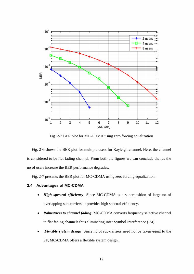
Fig. 2-7 BER plot for MC-CDMA using zero forcing equalization
Fig. 2-6 shows the BER plot for multiple users for Rayleigh channel. Here, the channel
is considered to be flat fading channel. From both the figures we can conclude that as the
no of users increase the BER performance degrades.
Fig. 2-7 presents the BER plot for MC-CDMA using zero forcing equalization.
2.4 Advantages of MC-CDMA
High spectral efficiency: Since MC-CDMA is a superposition of large no of
overlapping sub-carriers, it provides high spectral efficiency.
Robustness to channel fading: MC-CDMA converts frequency selective channel
to flat fading channels thus eliminating Inter Symbol Interference (ISI).
Flexible system design: Since no of sub-carriers need not be taken equal to the
SF, MC-CDMA offers a flexible system design.
1 2 3 4 5 6 7 8 9 10 11 1210
-5
10-4
10-3
10-2
10-1
100
SNR (dB)
BE
R
2 users
4 users
8 users

13
Easy Equalization: Since ISI is eliminated, equalization is almost not required.
High frequency diversity: Since MC-CDMA spreads the signal in frequency
direction it achieves high frequency diversity.
Fading resistance: Since it has high frequency diversity it is resistant to fading.
2.5 Disadvantages of MC-CDMA
High PAPR: Since it is a combination of large no of independent sub-carriers it
exhibits a very high PAPR.
Synchronous transmission: Maintaining synchronization is a difficult task in
MC-CDMA as the no of users increase.
2.6 Applications of MC-CDMA
MC-CDMA has a wide variety of applications in wireless communications. MC-CDMA
is used in multimedia services of 4G wireless communication system in air interface for
downlink scenario. It is a suitable modulation technique for indoor environments with
small delay spread and small Doppler spread. MC-CDMA transmission with a low
complexity iterative receiver is proposed for the PLC (power line communication)
channel.

14
3 SPACE TIME BLOCK CODES: A SPECIAL
FORM OF MIMO
Multiple Input Multiple Output (MIMO) [4] systems can be termed as the extension of
smart antennas. Smart antennas have multiple antennas at the transmitter or at the receivers
but not at the both. MIMO has multiple antennas at the transmitter and receiver. This
doesn’t mean that we have multiple transmitters and receivers. It simply means that we
have one transmitter and one receiver which are mounted with multiple antennas.
3.1 Functions of MIMO
MIMO can have different functions depending on its applications. MIMO can be
employed for diversity gain by transmitting same information on different antennas or can
be employed for capacity gain by transmitting information in parallel stream at the same
size.
3.1.1 Diversity
Diversity is a modulation technique which ensures that there is at least more than one
transmission path from the transmitter to the receiver. As there are multiple antennas,

15
MIMO system can be employed for diversity gain. MIMO transmits the same information
signal on different antennas thus increasing the reliability of the communication link since
it is less probable that all the paths will be affected by same amount.
3.1.2 Spatial Multiplexing (SM)
Also MIMO can increase the data rate by transmitting several information streams in
parallel at same transmit power. This is known as spatial multiplexing which is otherwise
known as multiplexing parallel information streams in space. In SM spectrum utilization
remains same. So data rate is very high. MIMO effectively takes advantage of multipath for
multiplying transfer rates.
3.1.3 Beamforming
Beamforming also known as spatial filtering is used for directional signal transmission.
In Beamforming, the average SNR is increased by focusing the energy in particular
direction. Beamforming can be used both at the transmitter and at the receiver to improve
spatial selectivity.
3.2 Space Time Block Code (STBC)
STBC is a special form of MIMO and is originally employed for 2 transmit antennas and
1 receiving antenna by Alamouti [5, 6]. Later it was generalized for any no of antennas. It
achieves a diversity order of 2 without Channel State Information (CSI) at the transmitter
and without bandwidth expansion.
3.2.1 STBC Encoding Scheme
The STBC encoding scheme is depicted in the following figure where there are 2 transmit
antennas and 1 receive antenna and the channel coefficients are Rayleigh flat fading
coefficients.

16
Fig. 3-1 STBC scheme for 2 transmit and 1 receive antenna
In the first symbol time interval, is transmitted from antenna 1 and is transmitted
from antenna 2 simultaneously, while in second symbol time interval antenna 1 transmits
and antenna 2 transmits
. The coding rate of this scheme is one since in two symbol
periods only two signals are transmitted, meaning that no bandwidth expansion takes place
[2]. Due to the orthogonality of the space-time block codes, the symbols can be separated at
the receiver by a simple linear combining scheme. At the receiver we can mathematically
model the received signal as follows:
Received signal at 1st time slot:
[ ] [
]
(3.1)
Received signal at 2nd
time slot:
[ ] [
]
(3.2)
where and are flat fading channel coefficients and and are noise
components which is generally Additive White Gaussian Noise (AWGN). In this
dissertation, the channel is assumed to be constant over the two time slots. The
following table summarizes the STBC encoding scheme.

17
Table 3-1 STBC Encoding scheme
space
time
3.2.2 STBC Decoding Scheme
For detection of signals, simple zero forcing (ZF) equalizer can be used. Now, the
received signal vectors from () and () can be stacked as
[
] [
] [
] [
] (3.3)
For detection of signals we can define,
Let [
] and [
]
We can define pseudo inverse as
(3.4)
Then the term,
[
] [
]
[
] (3.5)
Since the channel coefficients are orthogonal to each other we can have
and is a diagonal matrix, the inverse of this can be written directly as
[
]
(3.6)
To estimate the transmitted symbols we can employ
Antenna 1 Antenna 2
time t
time t+T
18
[
] [
] (3.7)
From (3.3),
( [
] [
]) (3.8)
[
] [
] (3.9)
The 2nd
term in above relationship is essentially noise.
3.2.3 Results and Discussion
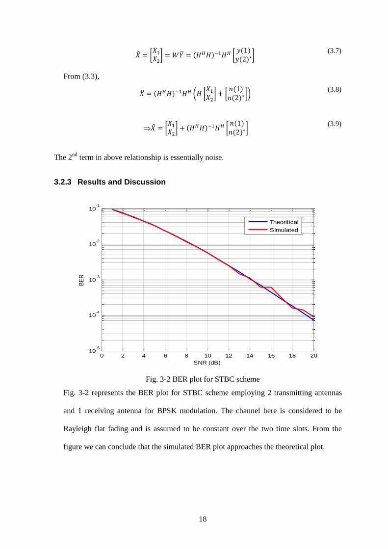
Fig. 3-2 BER plot for STBC scheme
Fig. 3-2 represents the BER plot for STBC scheme employing 2 transmitting antennas
and 1 receiving antenna for BPSK modulation. The channel here is considered to be
Rayleigh flat fading and is assumed to be constant over the two time slots. From the
figure we can conclude that the simulated BER plot approaches the theoretical plot.
0 2 4 6 8 10 12 14 16 18 2010
-5
10-4
10-3
10-2
10-1
SNR (dB)
BE
R
Theoritical
SImulated

19
3.3 STBC MC-CDMA: An integration of STBC and MC-CDMA
The STBC schemes are originally employed for flat fading channels. So application of
this scheme to frequency selective channels is challenging and has attracted attention of
many researchers. Multi-carrier techniques such as OFDM and MC-CDMA which convert
frequency selective channel to several flat fading channels are integrated with STBC to
produce STBC OFDM [7] and STBC MC-CDMA [10] respectively. This dissertation
mainly focusses on STBC MC-CDMA and its signal processing aspects. In STBC MC-
CDMA first CDMA operation is carried out and then OFDM operation is carried out.
3.4 STBC MC-CDMA Transceiver
STBC MC-CDMA transmitter and receiver block diagram for multiuser system is given
below for 2 transmit antenna and 1 receive antenna. The channel is Rayleigh flat fading
channel.
3.4.1 STBC MC-CDMA Transmitter
The baseband signal processing is presented at Fig. 3-3. The information bits of different
users are digitally modulated and then spreaded using orthogonal Walsh-Hadamard (W-H)
codes. All the spreaded signals are summed up to produce the CDMA signal and then
passed through STBC encoder. The STBC encoding is done as described in above section
3.2.1. Each of these STBC encoded outputs are passed through individual OFDM
modulators. In OFDM modulator part first the symbols are passed through the IFFT block
to convert frequency domain samples to time domain samples. After the IFFT operation the
samples must be separated from each other to ensure no inter symbol interference (ISI). For
that guard band or cyclic prefix (CP) can be used. After that the signals are transmitted
through channel.

20
Fig. 3-3 Transmitter block diagram of STBC MC-CDMA system
At the receiver first the CP is removed and then the channel equalization is carried out in
time domain as shown in Fig. 3-4. In the conventional STBC MC-CDMA [8] equalization
is implemented in frequency domain which increases the complexity by processing the
channel coefficients which are already present in time domain into frequency domain. For
detection of signal, simple ZF equalizer can be used which is described in 3.2.2.
After the channel effects are nullified the data are sent to the FFT block and the signals
are despreaded by using the same W-H code assigned to the specified user at the transmitter
side. Then the digital demodulation is carried out to retrieve all the user information bits.
Here the receiver must have the knowledge about the channel coefficients and the Walsh-
Hadamard code used for spreading at the transmitter accurately for correct detection of the
transmitted signals from different users. In the simulation, we have compared the STBC
MC-CDMA with STBC OFDM.

21
Fig. 3-4 Receiver block diagram of STBC MC-CDMA system
3.5 Results and discussion
Fig. 3-5 and Fig. 3-6 present that the STBC MC-CDMA performs better than STBC
OFDM under AWGN and Rayleigh channel. For BER of , STBC MC-CDMA
achieves a SNR gain of around 6 dB in AWGN and Rayleigh fading channel. In Fig. 3-7, it
is observed that as the no of users increase the BER performance degrades.
Fig. 3-5 BER performance of STBC OFDM and STBC MC-CDMA under AWGN
channel for single user

22
Fig. 3-6 BER performance of STBC OFDM and STBC MC-CDMA under Rayleigh
fading channel for single user
Fig. 3-7 BER performance for 2, 4 and 8 users for SF=4 of STBC MC-CDMA under
Rayleigh fading channel
23
4 PEAK TO AVERAGE POWER RATIO: AN
INTRODUCTION
In all multicarrier techniques Inverse Fast Fourier Transform (IFFT) is the main
building block for generation of orthogonal subcarriers. Occasionally, all the subcarriers
may get added to give a very high transmitted power. This high transmitted power may be
significant in deviation from the mean power giving rise to high Peak-to-Average Power
Ratio (PAPR) which is given as the ratio of maximum power to average power. This high
PAPR may affect the orthogonality of the subcarriers. Once the orthogonality is lost many
problems arise. High PAPR has been a bottleneck for multicarrier techniques.
Like all multi-carrier techniques, STBC MC-CDMA suffers from high PAPR. The
high PAPR of the transmitted signal which in turn results in high input-back-off (IBO) for
the power amplifier, drives the power amplifier to operate in non-linear region generating

24
inter modulation (IM) products. IM causes out-of-band emissions and in-band distortions.
Out-of-band emissions, or spectral regrowth, result an increased transmission bandwidth
and causes Adjacent Channel Interference (ACI) and in-band distortion causes self-
interference and degrades bit error rates performance at the receiver. So it is highly
essential to alleviate this problem. To combat the problem of high PAPR, many techniques
[5] have been proposed.
4.1 PAPR reduction techniques
There are so many PAPR reduction techniques exist. Some of the important PAPR
reduction techniques include
Clipping and filtering
Coding
Interleaving
Tone injection
Tone reservation
Active constellation extension
Selected mapping (SLM) and
Partial transmit sequence (PTS)
Among all the techniques, PTS [5, 6] is considered to be the best for PAPR reduction
scheme but at a cost of high computational complexity. Other techniques are application
specific but PTS and SLM are flexible. It has been seen in many occasions PTS has
performed better than SLM. Table 4-1 presents the comparison of all the PAPR
reduction techniques. Most of the PAPR reduction techniques reduce PAPR at a cost of
Bit Error Rate (BER) degradation, signal constellation distortion, increased complexity
etc. So choosing a good PAPR reduction technique is a difficult task.

25
Table 4-1 PAPR reduction techniques comparison
Technique name Power
increase Distortion-
less Loss in
data rate Computational
Complexity
Amplitude clipping & filtering No No No Low
Coding No Yes Yes Medium
Partial Transmit Sequence No Yes Yes Very High
Selected Mapping No Yes Yes High
Interleaving No Yes Yes Medium
Tone Reservation Yes Yes Yes Medium
Tone Injection Yes Yes No Medium
Active constellation extension Yes Yes No Medium
4.2 Mathematical model for PAPR calculation
Let denote data vectors such that [ ] where ,
being no of subcarriers. The time domain complex baseband representation of this data
block for a multicarrier signal can be represented as
{ }
√ ∑
(4.1)
Since the multicarrier signal is a combination of large no of independent subcarriers
it may exhibit high PAPR. The PAPR of the transmitted signal can be represented by
[[ ] ]
(4.2)
From the central limit theorem, the in-phase and quadrature phase components of
the time domain samples resemble Gaussian distribution with mean zero and variance of
for sufficiently large no of subcarriers [6]. The numerator in the above equation represents
the maximum power where the denominator is the average power which can also be termed

26
as variance of the time domain samples. In [7], PTS technique is applied to STBC MIMO-
OFDM systems. This thesis proposes to apply this technique to STBC MC-CDMA. Also, a
low complexity receiver for the above scheme is designed where the equalization is carried
out in time domain thus avoiding the need of converting time domain channel coefficients
to frequency domain. Time domain equalization is preferred over frequency domain
equalization because it is simple to implement and less complex.
4.2.1 Complementary Cumulative Distribution Function: A PAPR parametric
PAPR is characterized using Complementary Cumulative Distribution Function
(CCDF). The amplitude of the multicarrier signals follows Rayleigh distribution and power
distribution becomes central chi-square distribution [6, 5]. The Cumulative Distribution
Function (CDF) of amplitude of a signal sample can be represented as
(4.3)
where z is pre-set threshold. Then the CCDF can be defined as
CCDF=1- CDF (4.4)
Thus CCDF of the PAPR denotes the probability that the PAPR of a data block exceeds a
given threshold. Mathematically,
CCDF:
=
= where is no of subcarriers.
4.3 Results and discussion
Fig. 4-1 represents the CCDF plot for SISO PTS scheme in which number of subblocks are
taken as 4 and number of subcarriers are 128. In the figure, CCDF plot using PTS
technique, theoretical plot and the original CCDF plot without PTS scheme are represented.
It can be seen that CCDF performance improves significantly when PTS is used compared
to other two graphs and in turn PAPR is reduced.

27
Fig. 4-1 CCDF plot for SISO PTS scheme
1 2 3 4 5 6 7 8 9 1010
-3
10-2
10-1
100
PAPRthreshold
Pr(
PA
PR
>P
AP
Rth
reshold
)
Theoritical
PTS
Original without PTS

28
5 PARTIAL TRANSMIT SEQUENCE (PTS):
PAPR REDUCTION TECHNIQUE FOR SISO
AND STBC SYSTEM
Like all multi-carrier techniques, MC-CDMA also suffers from high PAPR problem. To
combat this problem many techniques have been proposed of which Partial Transmit
Sequence (PTS) is considered to be the best for PAPR reduction.
5.1 Partial Transmit Sequence (PTS)
A SISO PTS scheme for transmitter using OFDM [9, 10, 11] is presented in Fig. 5-1. In
SISO PTS, the input data block is divided into disjoint and equal length subblocks
such that the position of subcarriers assigned to one subblock is not assigned to other
subblocks. Hence,
∑
(5.1)
where is the data block. After subblock partitioning, IFFT operation is applied to
individual subblocks and then the time domain signals are weighted by phase factors

29
denoted as chosen from an allowed phase factor combinations as shown in Fig. 4-1. The
time domain signal after phase factor multiplication is presented as
∑
(5.2)
where [ ] and { }
The block diagram of conventional PTS is given below:
Fig. 5-1 Block diagram of a conventional SISO PTS scheme
The PAPR is calculated according to (4.2) and the signal with minimum PAPR is
transmitted. The phase factor combination which provides minimum PAPR is transmitted
as the side information (SI) to the receiver to rotate back the subcarriers so as to retrieve the
original data transmitted. The phase factors are chosen from a set of allowed phase factors
given by
(5.3)
where W is the set of allowed phase factors. Here, we have assumed that . For
example, for { }

30
The amount of PAPR reduction depends upon different subblock partitioning [12] and
no of sub-carriers chosen. There are different subblocks partitioning schemes such as
adjacent, interleaved, pseudo random etc.
1. Adjacent subblock partitioning:
The example of adjacent subblock partitioning is given below in Fig. 5-2.
Fig. 5-2 Adjacent subblock partitioning
In adjacent subblock partitioning if the no of data bits are multiple of no of
subblocks then first data bits are assigned to the 1st subblock and rest are
assigned zero. Similarly the 2nd
subblock will have non-zero values for next
data bits as shown above and rest are zero and so on. The amount of PAPR
reduction also depends upon the correlation that exists between the subblocks.
Adjacent subblock partitioning has very high correlation.
2. Interleaved subblock partitioning:
In interleaved subblock partitioning the subcarriers are assigned in a fixed
pattern interleaved by fixed amount of zeroes between two non-zero values. An
example of interleaved subblock partitioning is given in Fig. 5-3. Here, the
subcarriers are interleaved by two zeroes in all the subblocks. This subblock
partitioning still has some correlation between the subblocks since the
interleaving is carried out in a fixed manner.

31
Fig. 5-3 Interleaved subblock partitioning
3. Pseudo-random subblock partitioning:
Pseudo-random subblock partitioning is considered to be the best subblock
partitioning since it has better PAPR reduction capabilities than other subblock
partitioning schemes described above. The example of pseudo-random subblock
partitioning is given in Fig. 5-4 where the no of subcarriers assigned is in a
random manner. So there exists no correlation between the subblocks.
Fig. 5-4 pseudo random subblock partitioning
One thing to remember in the entire subblock partitioning schemes is that, the more the
no of subblocks the better it has PAPR reduction capabilities but at the cost of added
complexity. Also, when all the subblocks are summed up they will essentially be turned
into the original data stream.

32
5.2 Advantages and Disadvantages of PTS
Like all other PAPR reduction techniques PTS also has a wide set of advantages and has a
few serious draw backs.
5.2.1 Advantages of PTS
Distortion less technique: PTS doesn’t distort the signal in its processing.
Hence, Bit Error Rate (BER) performance is unaffected.
Compatible with arbitrary subcarriers and type of modulation: This technique
is unrestricted to no of subcarriers being used. Hence, data rate can be increased
by increasing the no of subcarriers within the same bandwidth. Also PTS
performance is unaffected with type of modulation being carried out for base
band modulation.
Flexible system design: Since it is compatible with arbitrary no of subcarriers
and any type of modulation, PTS offers a flexible system design with no
restriction on the parameters like no of subblocks and set of allowed phase
factors.
PAPR reduction capability: It has been proved that PTS is considered to be the
best PAPR reduction technique.
5.2.2 Disadvantages of PTS
High computational complexity: Very high computational complexity has
turned out to be the bottleneck for implementation of PTS technique in real time
systems despite of having very good PAPR reduction capabilities. The main
reasons for increased computational complexities include no of IFFT operations
for different subblocks which increase with as no of subblocks increase and
vigorous searching algorithm to find optimum phase factor from a large set of
phase factors.
33
Loss in data-rates: The phase factors used at the transmitter side to rotate the
subcarriers must be transmitted to the receiver to rotate back the subcarriers. This
is known as Side Information (SI) which is transmitted along with the OFDM
symbol. SI will reduce the data rate if it is significant.
5.3 Partial Transmit Sequence (PTS): PAPR reduction technique for STBC
MC-CDMA system
In previous section we have analyzed STBC MC-CDMA scheme and PTS
technique individually. This chapter focusses on application of PTS technique to STBC
MC-CDMA system. Also this section emphasizes on designing a low complexity
receiver for the above scheme.
5.4 PTS based STBC MC-CDMA Transceiver
PTS technique is applied to multiuser STBC MC-CDMA for downlink wireless
communication system for PAPR reduction and also a low complexity receiver is designed
for the above scheme. Both the transmitter and receiver schematic are explained below.
5.5 PTS based STBC MC-CDMA Transmitter
Fig. 5-5 represents the transmitter schematic of STBC MC-CDMA system in which the
users data are digitally modulated and spreaded using W-H orthogonal codes having
Spreading factor (SF) same for all the users for mathematical simplification. Then all the
spreaded information bits are summed up to provide the CDMA signal as denoted by in
Fig. 5-5. The CDMA signal is divided into two streams for encoding in STBC format for
two transmitting antennas as explained in Chapter 3. Now the PTS technique is applied.
The principle is to apply PTS technique to all the transmitting antennas individually.

34
Fig. 5-5 PTS based STBC MC-CDMA transmitter block diagram
In 1st time instant, is transmitted from transmitting antenna 1 and is transmitted
from transmitting antenna 2 and SISO PTS is applied to individual antennas. Then the
PAPR is calculated and the minimum PAPR will be transmitted from both the antennas.
Similarly, in 2nd time instant, is transmitted from antenna 1 and
from transmitting
antenna 2. The basic principle will be to apply again PTS technique to these two antennas
individually for PAPR reduction which will increase the complexity in a large proportion.
But such is not the case. It can be verified that the PAPR characteristics remain same for
both the transmitting antennas [10, 12]. So a simple mathematical phase factor conversion
will prevent from applying cumbersome PTS technique in the 2nd time interval and thus
will reduce the complexity by 50%. This technique is summarized in Fig. 5-6. In this
figure, only one transmitting antenna for two time intervals is presented. Application of this
technique to 2nd
transmitting antenna for both the intervals is straight forward.

35
Fig. 5-6 PTS in same transmitting antenna of STBC MC-CDMA
5.6 PTS based STBC MC-CDMA Receiver
After the minimum PAPR candidate signal is searched, it is transmitted after addition of
cyclic prefix (CP) through Rayleigh flat fading channel. Optimum value of phase factor
combination is found for the minimum PAPR candidate signal and is denoted as
[ ] (5.3)
This is known as Side Information (SI) which must be transmitted to the receiver side
for rotating back the subcarriers. The same procedure is applied for both the transmitting
antenna for finding out the SI in 1st time interval. For calculation of PAPR in 2
nd time
interval, simple phase factor conversion is required for the phase factor combination
obtained from the 1st time instant. Thus the optimum phase factor combination for 2
nd time
interval can be written as

36
(5.2)
Also the simulation results verify that for 2nd
time interval (i.e.
), the antennas
produce the same PAPR as is the case for the 1st time interval. So in STBC MC-CDMA
employing two transmitting antennas, we need to minimize PAPR for the 1st time interval
only.
Fig. 5-7 Block diagram of receiver structure for STBC MC-CDMA PTS scheme
The above diagram represents the receiver diagram for PTS based STBC MC-CDMA
scheme employing two transmitting antennas and one receive antenna. First the cyclic
prefix (CP) is removed from the noisy received signal. Then time domain equalization and
STBC decoding scheme is employed as described in Chapter 3. The equalization carried
out here is essentially Zero Forcing (ZF) to nullify the channel effects caused at the
transmitter. Since the equalization is carried out in time domain basis the signals available

37
after STBC decoding block is also in time domain. Now the signals must pass through the
FFT block to reverse the effects due to IFFT block at the transmitter. The PTS receiver
operation described in Fig. 5-7 can be mathematically modeled as given below.
Let denote the original data available such that [ ] , N being the
no of subcarriers. After partitioning into subblocks, let it be represented by . Then
IFFT operation is applied to this individual subblocks given by
{ } ( )
(5.4)
where is the IFFT matrix. Now if [ ] represents the optimum phase
factor then clearly the received signal vector
(5.5)
Now using (5.3), we can further write
(5.6)
(5.7)
(5.8)
Hence,
(5.9)
After the subcarriers are rotated back the data are multiplied with the same W-H code to
despread the signal of all the users. Then digital demodulation is performed to retrieve all
the transmitted bits of all the users.
5.7 Results and Discussion
Simulations were performed for adjacent subblock partitioning scheme with 4 subblocks
with BPSK modulation and phase factors were chosen from { } with a spreading
factor of 8. For BER plot Monte-Carlo simulation was used. CCDF graphs are plotted

38
between preset PAPR threshold and probability that PAPR exceeds this threshold along X-
axis and Y-axis respectively.
Fig. 5-8 CCDF plot for the same antenna at 1st and 2
nd time interval (8 users, SF=8,
W=4, M=4, N=128)
From Fig. 5-8, it is clearly seen that PAPR characteristics remain unaltered for the
same antenna in 1st and 2
nd symbol interval of STBC encoding scheme. So reduction of
PAPR is restricted to 1st symbol interval only. CCDF plot for STBC MC-CDMA PTS
scheme and SISO MC-CDMA PTS scheme are given in Fig. 5-9. Here, it can be seen
that SISO MC-CDMA has marginal better PAPR performance (around 0.3dB) than
proposed STBC MC-CDMA but at the cost of severe BER degradation which is
presented in Fig. 5-11. The cause of marginal enhancement of PAPR for STBC MC-
CDMA scheme than SISO MC-CDMA scheme may due to the fact that in STBC MC-
CDMA, two transmitting antennas are used which increases the transmitted power
which in turn increases PAPR. The theoretical CCDF plot and the original CCDF
without PTS are also plotted in Fig. 5-9 to differentiate the PAPR performance with and
without PAPR reduction technique, PTS.

39
Fig. 5-9 CCDF plot for STBC MC-CDMA PTS and SISO MC-CDMA PTS (SF=8,
W=4, M=4, N=128)
It is observed from Fig. 5-10 that as the no of users increase the CCDF performance
improves. This is due to the W-H code used for spreading which increases the average
value of the users data. As the users increase, the average value increases which in turn
decreases PAPR. In Fig. 5-10 CCDF plot for 2, 4 and 8 users have been plotted.
Fig. 5-10 CCDF plot of different users for STBC MC-CDMA (SF=8, W=4, M=4,
N=128)

40
Fig. 5-11 BER plot for STBC MC-CDMA and SISO MC-CDMA
In Fig. 5-11, the BER performance for STBC MC-CDMA and SISO MC-CDMA for 8
users is given which shows that STBC MC-CDMA outperforms SISO MC-CDMA. This
is due to the fact that the proposed STBC scheme achieves a diversity order of 2 which
improves the BER performance. From the graph, for BER of 10-3
, STBC MC-CDMA
achieves a SNR gain of around 8dB in comparison to SISO MC-CDMA at a marginal
increase in PAPR.
5.8 Complexity analysis of STBC MC-CDMA and SISO MC-CDMA
The complexities associated in both the SISO and STBC schemes are summarized in
Table 5-1. STBC scheme employing two transmitting antennas and one receiving antenna
performs better than SISO scheme. As the no of antennas are increased on either side of
transmitter or receiver, the PAPR will increase but at the same time the diversity order will

41
increase which in turn will improve the BER performance. So there is always a trade-off
when going for higher no of antennas to achieve minimum PAPR and better BER
performance.
Table 5-1 Complexity analysis associated with STBC MC-CDMA and SISO MC-
CDMA in terms of PAPR and BER performance

42
6 CONCLUSION
MC-CDMA has been the promising technology for 4G wireless communication system.
Since it is a combination of both OFDM and CDMA, it explores the advantages of both the
schemes. MIMO integrated with multicarrier techniques can boost the data rate and the
reliability of the link. Also by using multi antenna elements MIMO can achieve diversity
which in turn will improve BER performance thus improving the reliability at the receiver.
So STBC MC-CDMA is a suitable candidate in this regard which can achieve speed, range
and reliability simultaneously.
But the problem with multicarrier technique is PAPR which is also the major drawback
for STBC MC-CDMA and restricts its application. High PAPR causes intermodulation
products, increases the cost of the transmitter, and increases the complexity of the ADC. So
PAPR must be reduced at any cost. To reduce PAPR many methods have been proposed.
Most of the methods proposed are application specific such as they are only applicable to
binary signaling or particular no of subcarriers. But PTS is a flexible technique which is

43
applicable for any modulation scheme or any no of subcarriers. In this dissertation, PTS is
applied to STBC MC-CDMA for PAPR reduction. Since STBC employs 2 transmitting
antennas, PTS must be applied to both the antennas in both intervals. But implementation
of PTS is restricted to 1st symbol time interval only. The optimum phase factors obtained in
the 1st symbol interval is directly applied to the 2
nd symbol time interval with some simple
mathematical calculation. Hence the cumbersome task of applying PTS to 2nd
symbol time
interval for both the antennas is eliminated. So the complexity is reduced by 50%. Also a
low complexity receiver is designed for the above scheme where the receiver is assumed to
have knowledge of side information bits transmitted from the transmitter side after
obtaining the optimum phased factor. These bits are used for rotation back of the
subcarriers at the receiver side to retrieve the transmitted bits. The STBC encoding and
decoding scheme are operated in time domain. The proposed STBC MC-CDMA with PTS
technique is compared with SISO MC-CDMA with PTS technique in terms of CCDF and
BER performance. CCDF plots show that SISO MC-CDMA with PTS scheme performs
marginally better than STBC MC-CDMA with PTS scheme at a huge BER degradation.
CCDF and BER plots for multiple users have also been plotted and it can be concluded that
as the no of users increase the CCDF performance improves and BER performance
degrades.
6.1 Future Work
The PTS technique has huge computational complexities when it is required to find the
optimum phase factor from a set of large phase factor combinations. The complexity
increases exponentially with increase in number of subblocks and number of subcarriers.
So the future work can be derived from this drawback of PTS scheme.
Optimization algorithms can be developed for finding out the optimum phase factor
which produces the least PAPR. Thus the complexity can be reduced in a huge manner.

44
Another way to minimize PAPR is to optimize subblock partitioning schemes. Designing of
new subblock partitioning schemes can reduce the PAPR in a great deal.
In this dissertation we have assumed that the receiver has the knowledge about channel
coefficients. This may not be possible in adverse situations. So receiver side channel
estimation is essential for better reception of the signal. Also we have assumed that the side
information bits are known at the receiver. This means that additional spectrum is used for
transmission of these side information bits. This may lead to data loss if these bits are
significant. So the future work will be to estimate the transmitted bits without using side
information bits.

45
DISSEMINATION:
Behera, S. ; Patra, S.K. , “Performance analysis of low complexity multiuser STBC
MC-CDMA system”, SPRINGER International Conference on Intelligent Computing,
Communication and Devices (ICCD) 2014, Siksha ‘O’ Anusandhan University,
Bhubaneswar, Odisha, India, Apr 2014

46
BIBLIOGRAPHY
[1] L.-L. Yang, Multicarrier communications, John Wiley \& Sons, 2009.
[2] K. Fazel and S. Kaiser, Multi-carrier and Spread Spectrum Systems: From OFDM and
MC-CDMA to LTE and WiMAX, John Wiley \& Sons, 2008.
[3] S. Hara and R. Prasad, “Overview of multicarrier CDMA,” IEEE communications
Magazine, vol. 35, no. 12, pp. 126-133, 1997.
[4] A. J. Paulraj, D. A. Gore, R. U. Nabar and H. Bolcskei, “An overview of MIMO
communications-a key to gigabit wireless,” Proceedings of the IEEE, vol. 92, no. 2,
pp. 198-218, 2004.
[5] S. Alamouti, “A simple transmit diversity technique for wireless communications,”
Selected Areas in Communications, IEEE Journal on, vol. 16, no. 8, pp. 1451-1458,
1998.
[6] D. Gesbert, M. Shafi, D.-s. Shiu, P. J. Smith and A. Naguib, “From theory to practice:
an overview of MIMO space-time coded wireless systems,” Selected Areas in
Communications, IEEE Journal on, vol. 21, no. 3, pp. 281-302, 2003.
[7] M. D. Hassib, M. Singh, M. Ismail and R. Nordin, “Efficient and low complexity
STBC-OFDM scheme over fading channel,” in Communications (APCC), 2012 18th
Asia-Pacific Conference on, 2012.
[8] L. D'Orazio, C. Sacchi, R. Fedrizzi and F. G. De Natale, “An adaptive minimum-BER
approach for multi-user detection in STBC-MIMO MC-CDMA systems,” in Global
Telecommunications Conference, 2007. GLOBECOM'07. IEEE, 2007.
[9] S. H. Han and J. H. Lee, “An overview of peak-to-average power ratio reduction
techniques for multicarrier transmission,” Wireless Communications, IEEE, vol. 12,
no. 2, pp. 56-65, 2005.
[10] S. H. Muller and J. B. Huber, “A novel peak power reduction scheme for OFDM,” in
Personal, Indoor and Mobile Radio Communications, 1997. Waves of the Year 2000.
PIMRC'97., The 8th IEEE International Symposium on, 1997.
[11] V. Tarokh, H. Jafarkhani and A. R. Calderbank, “Space-time block codes from
orthogonal designs,” Information Theory, IEEE Transactions on, vol. 45, no. 5, pp.
1456-1467, 1999.
47
[12] S. G. Kang, J. G. Kim and E. K. Joo, “A novel subblock partition scheme for partial
transmit sequence OFDM,” Broadcasting, IEEE Transactions on, vol. 45, no. 3, pp.
333-338, 1999.
[13] Y. Li, M. Gao and Z. Yi, “A cooperative and alternate PTS scheme for PAPR
reduction in STBC MIMO-OFDM system,” in Communication Technology (ICCT),
2012 IEEE 14th International Conference on, 2012.
[14] J.-D. Chen, F.-B. Ueng, J.-C. Chang and H. Su, “Performance analyses of OFDM--
CDMA receivers in multipath fading channels,” Vehicular Technology, IEEE
Transactions on, vol. 58, no. 9, pp. 4805-4818, 2009.
[15] J. Gao, J. Wang and Y. Wang, “A low complexity PAPR reduction technique for
STBC MIMO-OFDM system,” in Wireless Communications, Networking and Mobile
Computing, 2007. WiCom 2007. International Conference on, 2007.