partially self-checking circuits and their use in...
TRANSCRIPT

SEL-73-039
Partially Self-Checking Circuits and Their
Use in Performing Logical Operations
bY
John F. Wakerly
August 1973
Technical Ref
ort No. 50 ; ISSUED IN JULY 1974 AS
COMPUTER SC1 NCE DEPARTMENT TECHNICAL REPORT NO. 420.
- This research was performed whileMr. Wakerly was a Fannie and JohnHertz Foundation Fellow; it wasa Iso pa rtia I ly supported by Na tiona I
1 Science Foundation Grant GJ-27527.

I
t
I
i
.:IL
bY
John F. Wakerly
SEL 73-039
PARTIALLY SELF-CHECKING CIRCUITS
AND THEIR USE IN PERFORMING LOGICAL OPERATIONS
August 1973
t
i Technical Report no. 50
DIGITAL SYSTEMS LABORATORY
Dept. of Electrical Engineering Dept. of Computer Science
Stanford University
Stanford, California
This research was performed while Mr. Wakerly was a Fannie and JohnHertz Foundation Fellow; it was also partially supported by NationalScience Foundation Grant GJ-27527.

LABSTRACI'
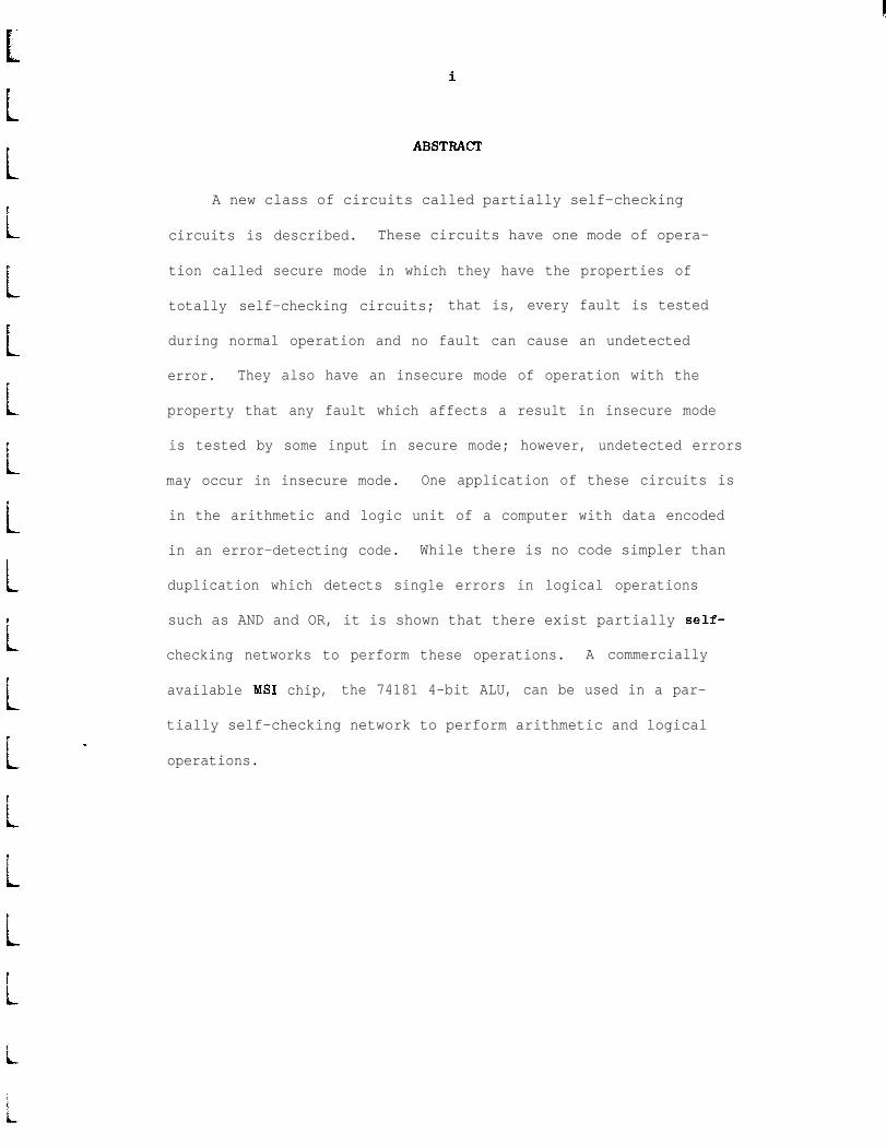
A new class of circuits called partially self-checking
LcL!LLLP
i
i
,
i
-
circuits is described. These circuits have one mode of opera-
tion called secure mode in which they have the properties of
totally self-checking circuits; that is, every fault is tested
during normal operation and no fault can cause an undetected
error. They also have an insecure mode of operation with the
property that any fault which affects a result in insecure mode
is tested by some input in secure mode; however, undetected errors
may occur in insecure mode. One application of these circuits is
in the arithmetic and logic unit of a computer with data encoded
in an error-detecting code. While there is no code simpler than
duplication which detects single errors in logical operations
such as AND and OR, it is shown that there exist partially self-
checking networks to perform these operations. A commercially
available MS1 chip, the 74181 4-bit ALU, can be used in a par-
tially self-checking network to perform arithmetic and logical
operations.
L
tL

I
ii
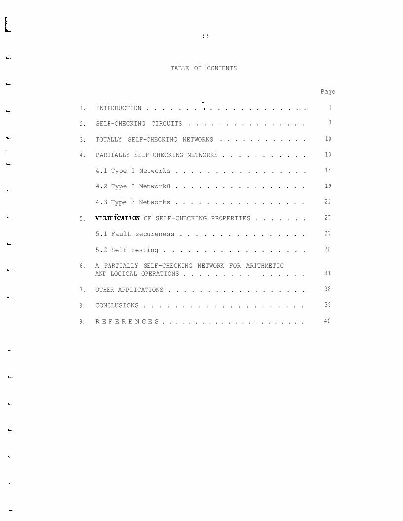
TABLE OF CONTENTS
6. A PARTIALLY SELF-CHECKING NETWORK FOR ARITHMETICAND LOGICAL OPERATIONS . . . . . . . . . . . . . . . .
7. OTHER APPLICATIONS . . . . . . . . . . . . . . . . . .
8. CONCLUSIONS . . . . . . . . . . . . . . . . . . . . .
9. R E F E R E N C E S . . . . . . . . . . . . . . . . . . . . . .
1. INTRODUCTION . . . . . . . ', . . . . . . . . . . . . .
2. SELF-CHECKING CIRCUITS . . . . . . . . . . . . . . . .
3. TOTALLY SELF-CHECKING NETWORKS . . . . . . . . . . . .
4. PARTIALLY SELF-CHECKING NETWORKS . . . . . . . . . . . 13
4.1 Type 1 Networks . . . . . . . . . . . . . . . . . 14
4.2 Type 2 Network8 . . . . . . . . . . . . . . . . . 19
4.3 Type 3 Networks . . . . . . . . . . . . . . . . . 22
5. VERIFiCATION OF SELF-CHECKING PROPERTIES . . . . . . . 27
5.1 Fault-secureness . . . . . . . . . . . . . . . . 27
5.2 Self-testing . . . . . . . . . . . . . . . . . . 28
Page
1
3
10
31
38
39
40


iii
LIST OF FIGURES
t
i
Figure
1.1 Self-checking circuit ‘; . , . . . . . . . . . . .
2.1 Self-testing circuit . . . . . . . . . . . . . . .
2.2 Fault-secure circuit . . . . . . . . . . . . . . . 5
2.3 Examples of self-testing and fault-secureness . . 6
3.1 Totally self-checking bus driver . . . . . . . . . 11
3.2 Totally self-checking network . . . . . . . . . . 11
L
4.1 Totally self-checking bus switch . . . . . . . . .
4.2 Type 1 partially self-checking network . . . . . .
4.3 Partially self-checking parity-checked bus driver.L
4.4 Totally self-checking checker for separate codes .
4.5 Type 2 partially self-checking network . . . . . . 21
4.6 Type 3 partially self-checking network . . . . . . 23
6.1 Bit slice to perform any logic function of twovariables . . . . . . . . . . . . . . . . . . . .
6.2 Partially self-checking ALU using 74181 4-bitALUchips ., . . . . . . . . . . . . . . . . . .
Page
2
5
13
15
18
19
32
37


f ’e
6i
!
i
i
L
iL
/L
iii
iv
LIST OF TABLES
Table Page
6.1 Functions performed by the circuit of Fig. 6.1 . . 33
6.2 Fault tests for the circuit of Fig. 6.1 . . . . . . 34
L

r
L
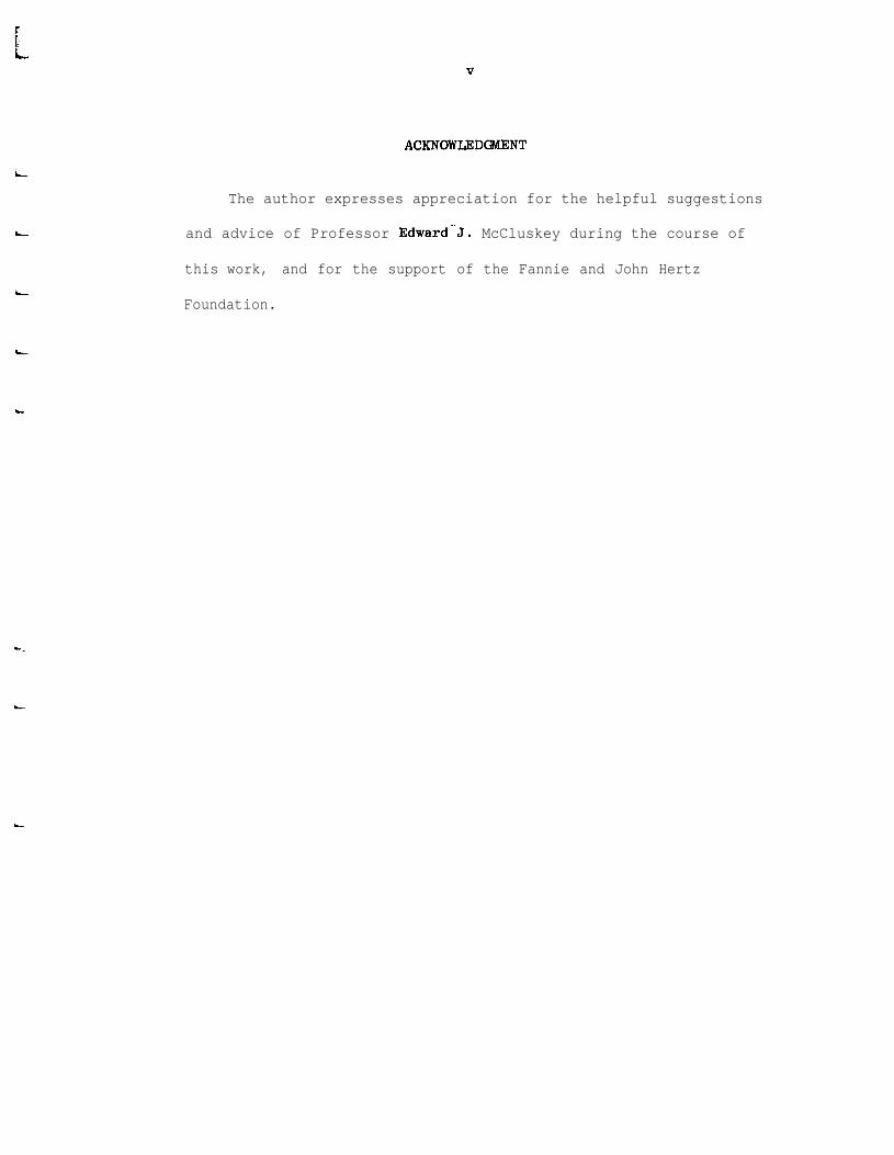
ACKNOWLEDMENT
L
The author expresses appreciation for the helpful suggestions
and advice of Professor Edward"J. McCluskey during the course of
this work, and for the support of the Fannie and John Hertz
Foundation.
L

!.’

cLLLrt1c
1
L
LiL
I
L
/L
i
i
-l-
1. INTRODUCTION
One approach to error detection in fault-tolerant computers is
through the use of self-checking circuits, explored by Carter and
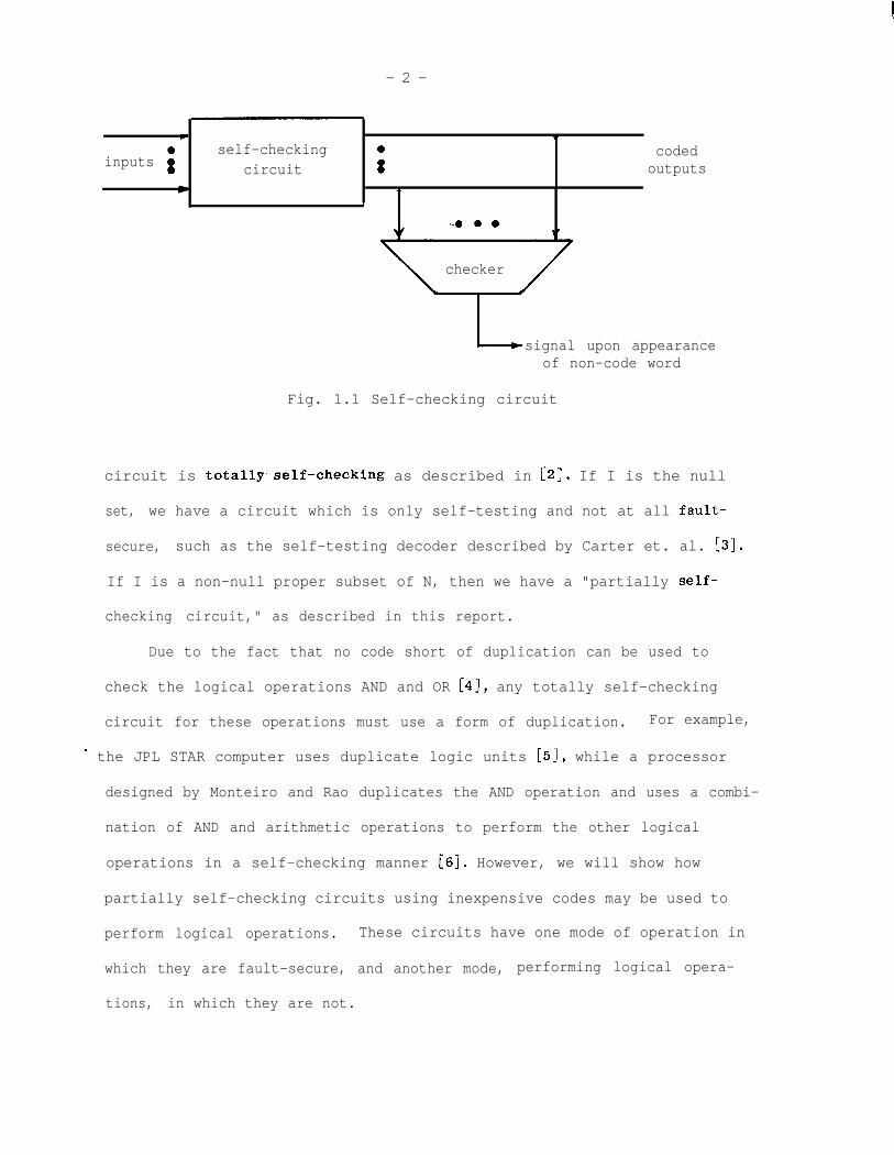
Schneider [l] and also by Anderson [2]. As suggested by Fig. 1.1, the
output of a self-checking circuit is encoded in some error-detecting code
so that faults may be detected by a checker which monitors the output
and signals the appearance of a non-code word. A self-checking circuit
has properties of "self-testing" and "fault-secureness" introduced in [l]
and formally defined by Anderson [2].
Definition Al: A circuit is self-testing if, for every fault from a
prescribed set, the circuit produces a non-code space
output for at least one code space input.
Definition A2: A circuit is fault-secure if, for every fault from a
prescribed set, the circuit never produces an incorrect
code space output for code space inputs.
Anderson's definitions imply the existence of a "code spacetl from
which normal inputs are drawn, and for which the circuit is both self-
- testing and fault-secure. This facilitates his definition of a "totally
self-checking circuit," a circuit which is both self-testing and fault-
secure. Actually, a circuit may be self-testing for the set of normal
code space inputs, but fault-secure for only a subset. In this report
we formulate a theory of self-checking circuits that are self-testing for
an input set N and fault-secure for a subset I of N. If I equals N, the
i
- 2 -
4 wa self-checking 0 coded
inputs 0 00 circuit 0 outputsw w
J
-4 0 a
checker
signal upon appearanceof non-code word
Fig. 1.1 Self-checking circuit
circuit is totally.self-checking as described in [2]. If I is the null
set, we have a circuit which is only self-testing and not at all fault-
secure, such as the self-testing decoder described by Carter et. al. [3].
If I is a non-null proper subset of N, then we have a "partially self-
checking circuit," as described in this report.
Due to the fact that no code short of duplication can be used to
check the logical operations AND and OR [4], any totally self-checking
circuit for these operations must use a form of duplication. For example,
- the JPL STAR computer uses duplicate logic units [5], while a processor
designed by Monteiro and Rao duplicates the AND operation and uses a combi-
nation of AND and arithmetic operations to perform the other logical
operations in a self-checking manner [6]. However, we will show how
partially self-checking circuits using inexpensive codes may be used to
perform logical operations. These circuits have one mode of operation in
which they are fault-secure, and another mode, performing logical opera-
tions, in which they are not.
- 3 -
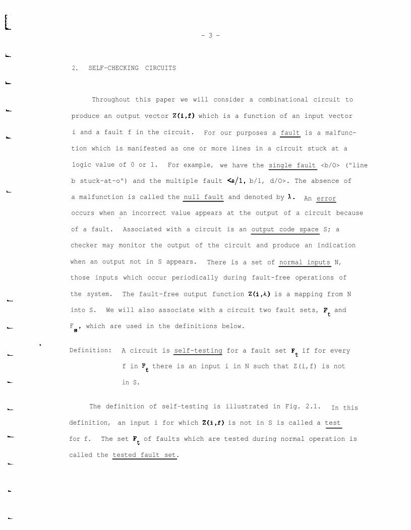
2. SELF-CHECKING CIRCUITS
L
Throughout this paper we will consider a combinational circuit to
produce an output vector Z(i,f) which is a function of an input vector
i and a fault f in the circuit. For our purposes a fault is a malfunc-
tion which is manifested as one or more lines in a circuit stuck at a
logic value of 0 or 1. For example, we have the single fault <b/O> ("line
b stuck-at-o") and the multiple fault Q/l, b/l, d/O>. The absence of
a malfunction is called the null fault and denoted by A. An error
occurs when an incorrect value appears at the output of a circuit because-=.
of a fault. Associated with a circuit is an output code space S; a
checker may monitor the output of the circuit and produce an indication
when an output not in S appears. There is a set of normal inputs N,
those inputs which occur periodically during fault-free operations of
the system. The fault-free output function Z(i,A) is a mapping from N
into S. We will also associate with a circuit two fault sets, Ft and
FS’
which are used in the definitions below.
Definition: A circuit is self-testing for a fault set Ft if for every
f in Ft there is an input i in N such that Z(i,f) is not
in S.
The definition of self-testing is illustrated in Fig. 2.1. In this
definition, an input i for which Z(i,f) is not in S is called a test
for f. The set Ft of faults which are tested during normal operation is
called the tested fault set.

-4-
Definition: A circuit is fault-secure for an input set I and a fault
set Fs if for any i in I and for any f in Fs either
Z(i 3) = Z(i,h) E S or Z(i,f) j!L S.
Fig. 2.2 illustrates the above definition. The set I is called the
secure input set. We will always assume that I is a subset of the normal
input set N. Although the circuit may be fault-secure for some inputs
outside of N, these inputs are not of interest since they do do occur
in normal operation.
The set Fs above is called the secure fault set. We will always assume
for convenience that Fs is a subset of the tested fault set Ft*For sup-
pose there is a fault f in Fs which is not in Ft. Then there is no input-
among all the normal inputs for which an erroneous output is produced in
the presence of f, and the fault is not an interesting one to consider.
(However, multiple faults including f as a component may be of interest.)-
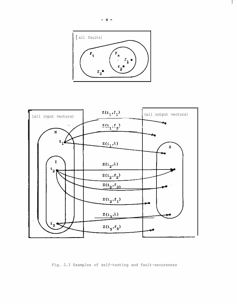
The properties of self-testing and fault-secureness are illustrated
in Fig. 2.3. This figure shows the set of all faults and its subsets Ft
and FS’
the set of all input vectors and its subsets N and I, and the set
eof all output vectors and its subset S. In the absence of faults, inputs
from N produce outputs in S, as shown by the behavior in i1' i2 t and i
3'
Self-testing is shown by noting that for each of the faults fl, f2, and f3
in Ft there is a test in N (i1' i3, and i 1 respectively). Fault-secureness
is illustrated by the behavior of Z(i2,f) for various f. In the presence
of a fault from Fs, the output is either correct (Z(i2,f2)) or it is a
non-code word (Z(i2,fl)). However, faults outside of Fs may produce
erroneous code word outputs (Z(i 2�f3)l l Circuits which are self-testing
and fault-secure for some sets of inputs and faults are self-checking.

c -5-
l
any i E N ll*
fault-freel
0 Z(i,A) E Sa
. .
i
L
i
L
L
somel 0
icN l any fault in Ft 0 Z(i,f) f! Sl 0
t
Fig. 2.1 Self-testing circuit
/ C’
0 l
any i E I 0 fault-free l Z&A) E Sl l
/
anyiE1 l any fault in FS
= Z&h) f S
or Z(i,f) j! S
Fig. 2.2 Fault-secure circuit
I
-6-
all faults]
Ft FS
]
. .fl"
f3ef2e
-
[all input vectors)Z(+fl) I (all output vectors]
I
-=. Zti .fl -TT
Fig. 2.3 Examples of self-testing and fault-secureness
L -7-
L
c
L
i
L
L
L-
I
L
L
L
L
L
L
L
L
Definition: A combinational circuit with normal input set N and output
code space S is self-checking if it is self-testing for a
fault set Ft and fault-secure for an input set I and fault
set F .S
For a self-checking circuit to be of any value, Ft and Fs should be
reasonable fault sets, containing say all the single stuck-at faults.
During normal operation of a self-checking circuit, all reasonable
faults are detected because of the self-testing property. In addition,
fault-secureness guarantees there is no undetected erroneous output when
inputs are from I. If I is equal to N, then the circuit is "totally
self-checking."
Definition; A totally self-checking circuit is a self-checking circuit
for which the set I of secure inputs equals the set N of
normal inputs.
In a totally self-checking circuit, no fault in Fs can cause an
undetected error for any normal input to the circuit. At the other
extreme are circuits for which there is no non-null choice of I for
which the circuit is fault-secure.
Definition: A self-testing circuit is a self-checking circuit for which
the set I of secure inputs is the null set.*
An example of a self-testing circuit is the self-testing decoder of
Carter et. al. r31.. For any input to this circuit there is a single
*Obviously self-testing circuits may also be defined without referenceto self-checking circuits. However, this definition is included forconsistency and completeness.

-8-
stuck-at fault which will cause an erroneous code word output, and thus
I must be the null set.
Between the two extremes of self-testing and totally self-checking
circuits are partially self-checking circuits.
Definition: A partially self-checking circuit is a self-checking circuit
for which the set I of secure inputs is a non-null proper
subset of the set N of normal inputs.
When inputs to a self-checking circuit are from I, the circuit is
said to operate in secure mode. A totally self-checking circuit always--.
operates in secure mode. When inputs are from the set I' = N - I, the
circuit operates in insecure mode. A self-testing circuit always oper-
ates in insecure mode. A partially self-checking circuit operates
sometimes in one mode, sometimes in the other.
The effectiveness of totally and of partially self-checking circuits
may now be compared. With a totally self-checking circuit, any output
which is in the code space is correct if no faults outside of FS
occur,
and any fault in F is detected by the first error it produces. Ifa S
only faults from FS occur, no erroneous results may be transmitted.
In secure mode, a partially self-checking circuit has these same desirable
properties. But in insecure mode, erroneous results may be transmitted.
The likelihood of an undetected error in insecure mode is propor-
tional to the frequency of operation in this mode. If this mode is
infrequent, chances are that a fault will be detected in secure mode
before any result in insecure mode is affected. Even when a solid fault
produces an undetected error in insecure mode, it will soon be detected
P”
t
-9-
L
L
L
L
L
in secure mode. At this point a software rollback scheme might be used
to erase the effect of possible undetected errors.
Unfortunately, there is still..a chance in insecure mode of trans-
mitting errors caused by short transient faults that are never detected.
Although this possibility is very small, it may be sufficient to rule
out the use of partially self-checking circuits in highly critical
applications where ultra-reliability is required and the chance of tran-
sients is high. But for less critical applications, partially self-
checking circuits can provide a good deal of low-cost error detection in
areas where corresponding totally self-checking circuits are much more
expensive. In particular, we will show networks for logical operations
which are partially self-checking, but first we introduce a model of
totally self-checking networks.
L
c
- 10 -
3. TOTALLY SELF-CHECKING CIRCUITS AND NETWORKS
In dealing with totally self-checking circuits we will mention
only the set N of normal inputs because the set I of secure inputs is
the same. A trivial example of a totally self-checking circuit is a
bus driver for n-bit parity-encoded operands, illustrated in Fig. 3.1.
The circuit consists simply of n identical bus driver gates (one-input
AND gates), one for each output bit. The output code space S and the
normal input set N both equal the set of all even-parity n-bit vectors.
The circuit is fault-secure for all single faults, since a single fault-=.
causes either no error for a particular input, or a distance-one change
in the output producing an odd-parity vector. The circuit is also self-
testing for all stuck-at faults which affect less than n bits, since for
any such fault there is an even-parity input vector which produces an
odd-parity output in the presence of the fault. A checker which produces
a signal when an odd-parity vector appears may be used to monitor the
output of the circuit, as suggested by Fig. 1.1. Actually, we would
e like the checker also to be totally self-checking so that a fault in the
checker also produces an error indication. This leads us to the concept
of totally self-checking networks.
Anderson gives the model of Fig. 3.2 of a totally self-checking net-
work consisting of a functional circuit and a checker which are both
totally self-checking [2]. In terms of the notation presented here, the
functional circuit has a fault-free output function which is a surjection
from a normal input set Nf onto an output code space Sf'
while the checker
- 11 -
i
i
i
L
i
i
h
i
an-l IAn-l
--.
Fig. 3.1 Totally self-checking bus driver
I-
---w-w----------- ------------
1
t I
inputs i f
I
selr-cnecaing
E Nffuncl' - I a
I .I
C&Tcxllr;
II I
l
Itotally
. d -L - -.-* -- - I - ioutputs E Sf
II
:ional---1 L I 0 I
t 1 IIIIIIIIIII
l Iinputs tE N I
CI
checker/
I
outputs E s IC--we-- - - - - - - - A
I
errorindicator
Fig. 3.2 Totally self-checking network
l
- 12 -
= Sf and an output code space SC = (dol>,aO>).*
has a normal input set NC
The fault-free output function of the checker is a code disjoint mapping,
that is, it always maps non-code inputs into non-code outputs. With-.
these constraints it is easy to show that the network itself is totally
self-checking (for example, see Thm. 3.2 of [2]). The normal input set
of the network is Nf'
while its output code space is S . The secure andC
tested fault sets of the network are the unions of the corresponding
fault sets of the functional circuit and the checker.
A simple example of a totally self-checking network employs the
totally self-checking n-bit bus driver of Fig. 3.1 and an e-bit odd
parity generator. The odd parity over n-l bits together with a wire
connected to the remaining bit comprise the required two-output totally
self-checking parity checker.
*The checker must have two lines encoded in this manner, for a faultsticking a single error indicator line at the "good" value would neverbe detected. #

i
r
i
iL
I
t
L
fi
:IL
iL.
i
i
- 13 -
4. PARTIALLY SELF-CHECKING NETWORKS
The use of and motivation for.partially self-checking circuits is
best given by an example. Suppose we have a machine with buses A, B,
and T that carry data encoded in a single error detecting code S. Fig.
4.1 shows one bit slice of a bus switch which can transfer either A or
B to T. This circuit is replicated once for each bit to be switched.
The lines (slso> are set to 41, to transfer A to T and to ClO> to
transfer B. A checker may then monitor the T bus with the appearance of
a non-code word signaling an error. The reader can easily verify that
the circuit is fault-secure for all stuck-at faults which affect only a
single bit slice, and self-testing for all stuck-at faults which affect
fewer than all the bit slices. Thus the circuit is totally self-checking
when used as a bus switch in this manner.
Looking at the circuit of Fig. 4.1 we notice that it may also be
used to compute the logical OR of A and B by setting <slso> to al,.
Unfortunately, the result in general will not be valid because the encod-
ing of the logical OR of two operands does not in general equal the
Ti
Fig. 4.1 Totally self-checking bus switch
I
- 14 -
logical OR of their encodings unless the encoding is at least complete
duplication [4]. Suppose however that the encoding is a separate code,
that is, a code with a separate data part and check symbol. Then the OR
of the data parts will be correct; only the check symbol output will be
wrong. We can then calculate a new check symbol based on the data out-
put of the circuit and utilize the re-encoded output. This is a practical
scheme only if it can be implemented in a self-checking manner at low
cost. In the remainder of this section we show models of partially self-
checking networks which fulfill that requirement.--.
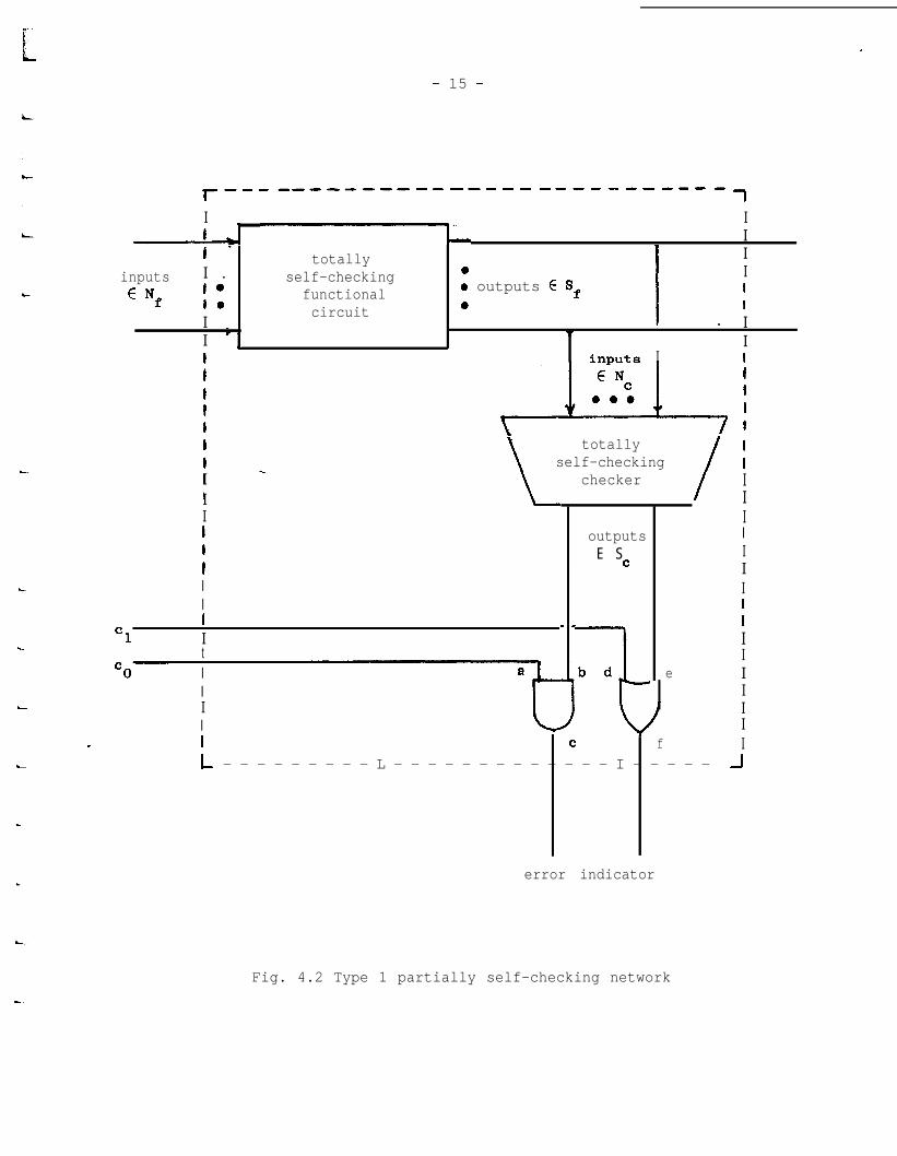
4.1 Type 1 Networks
The simplest partially self-checking network is the type 1 model,
shown in Fig. 4.2. It consists of a totally self-checking functional
circuit with a fault-free output function which is a mapping from a
normal input set N Sf
onto an output code spacef; a totally self-checking
checker with normal input set NC
= Sf and output code space SC =
{aOl>,ClO>); and two control gates and the control leads cl and co.
The vector elco> may be set to aDl> to enable the output of the checker,
or to ClO> to force the error indicator output to ClO> ("good").
The output code space of the network is just SC. However, the
normal input set of the network consists of vectors of the form <G c1 0i>
where cl and co are the control gate inputs and i is the functional
circuit input. When functional circuit inputs from Nf are expected,
c
L
L
L
*
- 15 -
r ----------------------------- 7I I. .
r 1L II - totally I
inputs I . self-checking a
I .
I
ENf I:functional 0 outputs E Sf I
circuit 0 II _ II -*
7
II
I i nnilta I
\totally
self-checkingchecker
/I
I LIIIIIII
c1 It
cO IIII
outputsE S
C
b d
t
e
IIIIIIIII
IIIIIIII- I C f
L - - - - - - - - - L - - - - - - - - - - - - - I - - - - - J
error indicator
Fig. 4.2 Type 1 partially self-checking network

I
- 16 -
elco> is set to 81> and the network is logically equivalent to the
totally self-checking network of Fig. 3.2. However, when inputs not in
Nf are expected <clco> may be set to Cl07 to disable the checker.-.
It is straightforward to show that the network of Fig. 4.2 is
partially self-checking when used in the manner described above. Let
Fa be the set of all single stuck-at faults on the control gates. That
is,
Fa = b/O, a/L b/O, b/L c/O, c/L d/O, d/L e/O, e/l, f/O, f/l]
Then the secure and tested fault sets of the network contain F as wella
as the corresponding fault sets of the functional circuit and checker.
The secure input set of the network is In, where
In = (cClcoi> 1 (&lco> = <ol>) A (iGNf)).
In insecure mode, the network has inputs from the set I',n
1; = (<clcoi> 1 e1c07 = 4073.
Thus the normal input set of the network is Nn - In U In.
Theorem 4.1: A type 1 network, described above and illustrated in
Fig. 4.2, is partially self-checking.
Proof: In secure mode, that is, with inputs from In, the network is
clearly self-testing and fault-secure for faults from the
appropriate fault sets of the functional circuit and checker.
It follows that the network is also self-testing with inputs
from Nn since N,31 .n
Thus we need only show self-testing and
fault-secureness for faults from Fa.
LL
- 17 -
Fe
1II
I
L
1i someinputinN =InUI'.
n n
L
1
(a) (self-testing) All faults except <a/l7 and <d/O> are
tested by some input from In, since a and d have the
values 1 and 0 respectively during such operation, and
both O's and l's must be transmitted through the paths
627 and <ef>. This is true because each checker output
takes on both values 0 and 1. The faults <a/l> and a/O7
are each detected by sOme input from I', since one of thesen
faults changes the correct error indicator output of Cl07
to a non-code word. Thus all faults in Fa are tested by
(b) (fault-secureness) It is clear that a single fault from
Fa causes at most a distance one change in the error indi-
cator output, producing either the correct output or a
non-code word. I:
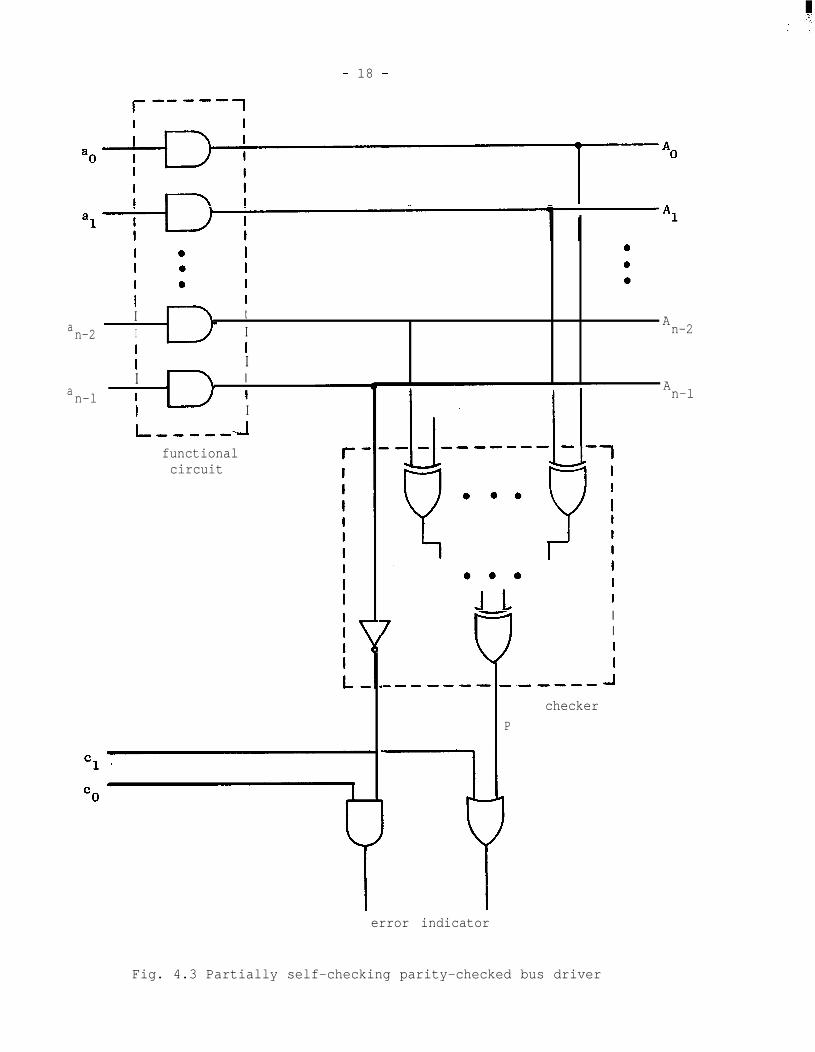
1 An example of a type 1 partially self-checking network is the n-bit
parity checked bus driver shown in Fig. 4.3. The totally self-checking
functional circuit here is the n-bit bus driver of Fig. 3.1, while the-
totally self-checking checker consists of an n-l-bit even-parity generator
and an invert-er eonmeted to the remaining data bit. The control vector
.cC1c07 is set to a)17 when even-parity operands are to be transmitted,
and to Cl07 for vectors of unknown parity.
The usefulness of type 1 networks is limited since in insecure mode
they do not re-encode the functional circuit output. We notice in the
ii
example of Fig. 4.3 that the correct parity output is always available
from the parity generator at line E, and could be utilized at essentially
zero cost. Type 2 networks are a formalization of this idea.
- 18 -
al A1
I 0 I 0
I 0 I 0
I 0 I 0
I II t
a An-2 I I n-2
I II II I
an-l I I
I I
I ,!-Mm----
functionalcircuit
7
IIII
I.-I)---- -.--we- 1
checker
P
error indicator
An-l
Fig. 4.3 Partially self-checking parity-checked bus driver
- 19 -
4.2 Type 2 Networks
L
i
L
L
L
L
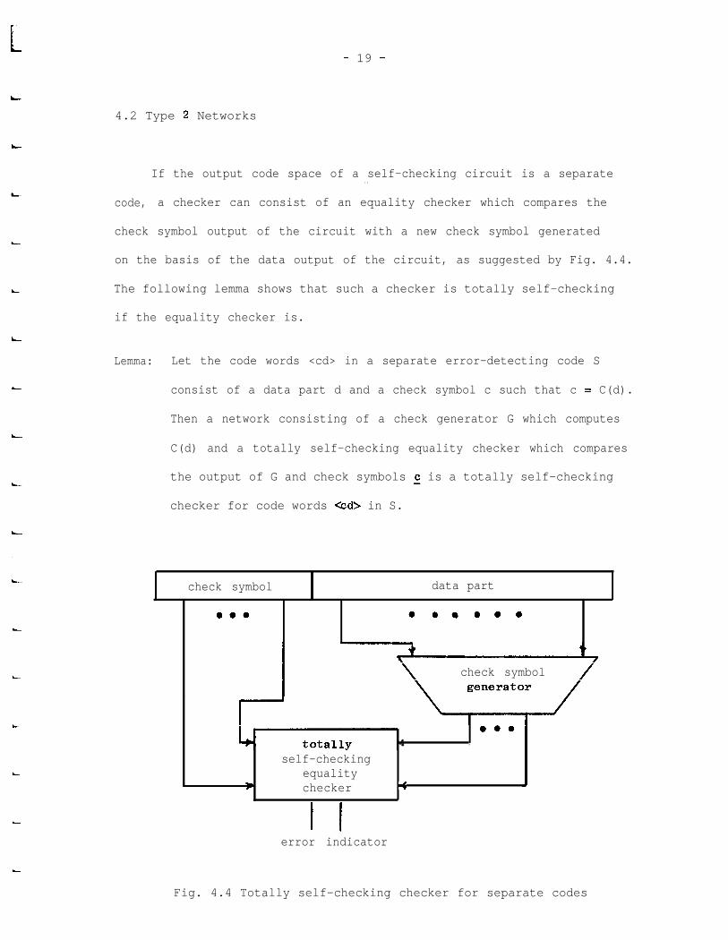
If the output code space of a self-checking circuit is a separate. .
code, a checker can consist of an equality checker which compares the
check symbol output of the circuit with a new check symbol generated
on the basis of the data output of the circuit, as suggested by Fig. 4.4.
The following lemma shows that such a checker is totally self-checking
if the equality checker is.
Lemma: Let the code words <cd> in a separate error-detecting code S
consist of a data part d and a check symbol c such that c = C(d).
Then a network consisting of a check generator G which computes
C(d) and a totally self-checking equality checker which compares
the output of G and check symbols s is a totally self-checking
checker for code words <cd> in S.
check symbol data part.
0.0 0.~0..
check symbol
0.04 .
self-checkingequality
P checker <
I Ierror indicator
Fig. 4.4 Totally self-checking checker for separate codes
- 20 -
Proof: The normal input set of the network is S, while the output code
space of the network is the output code space of the equality
checker. Let Fg be the set of all check generator faults which
produce an incorrect generator output for at least one network
input in S. Clearly faults outside of F have no effect on theEt
network. The reader can easily verify that the network is
self-testing and fault-secure for faults in F , as well as for45
faults in the tested and secure fault sets of the equality
checker. The tested and secure fault sets of the network are .
the appropriate unions of the above sets. l
The proof of the above lemma depends primarily on the existence of
.a totally self-checking equality checker for k-bit check symbols c. If-
the k-bit vectors do not take on all 2k possible values then a checker
might not exist. However, if the k-bit vectors do take on all values
then we are assured of the existence of a totally self-checking equality
checker regardless of the value of 5 [Z].
A type 2 network, shown in Fig. 4.5, is a type 1 partially self-
checking network which uses the totally self-checking checker for separate
codes described above, and which has a re-encoded functional circuit out-
put-derived from the check generator. The input sets, fault sets, and
output code space of a type 2 network are the same as those of the
corresponding type 1 network. Thus ignoring the re-encoded functional
circuit output, a type 2 network is merely a type 1 network with more
detail specified, and hence is partially self-checking. However, it
does have a re-encoded functional circuit output available, and the

- 21 -
r-a----v---w-------e------w---
1I II
I
t l dataII data
I . totally l part I partinputs 1 l self-checking I v
ENf IO functional 4
I circuit l checkl symbol
I
I
I
IIIII
I
Itt1ttItt
I
II
function
0.0output
?checksymbol
generator/
I
totallyself-checking
equalitychecker
I check1 symbol
error indicator
Fig. 4.5 Type 2 partially self-checking network

- 22 -
appearance of a non-code word here is reflected by the checker output,
since the checker function is a code disjoint mapping. These results
are summarized in the following theorem...
Theorem 4.2: A type 2 network, described above and illustrated in
Fig. 4.5, is partially self-checking. Furthermore, in
the absence of faults, the re-encoded functional circuit
output is always a code word; the appearance of a non-
code word because of a fault is reflected by a non-code
output of the checker.
4.3 Type 3 Networks
A noticeable disadvantage of type 2 networks is that the functional
circuit output is delayed by the re-encoding process using the check
generator. In a totally self-checking or type 1 partially self-checking
network the total delay is that of the functional circuit alone, while
in a type 2 network it is the sum of the functional circuit and check
generator delays.
introduce some delay, but a type 3 network reduces the delay in secure
In insecure mode the re-aencoding process will always
mode to two gate delays.
A type 3 network, illustrated in Fig. 4.6, consists of a totally
self-checking functional circuit and equality checker, a check generator,
and control gates to switch either the functional circuit check symbol
output or check generator output to the network output. The equality
checker compares the network check symbol output with the generated
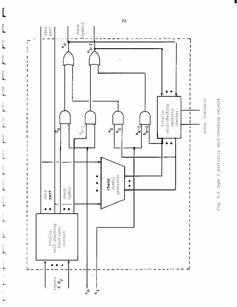
I-
------------
---------a-----
---a----------
----
-a-
l
I I
I
I
totally
self-checking
functional
circuit
0data
' data
0pa
rt' part
IT
Iinputs
E Nf
I=
I l
II
0
I
check
0symbol
I
symbol
I\
generator
/
I i I I I I I I I I
Jdk-l
I. 4
Itotally
0self-checking
00
equality
0*
Ichecker
I I I I Icheck
I symbol
I I I I I I I I I I I I I I I 1 I I I I I
error indicator
Fig. 4.6 Type 3 partially self-checking network
- 24 -
check symbol. When *lcO> equals a>17 (secure mode), the network is
logically equivalent to a totally self-checking network; when <clcO>
equals 40, (insecure mode), the functional circuit is re-encoded
and the equality checker compares the generated check symbol with itself,
producing a "good" output.
The normal input set, secure input set, and output code space of
a type 3 network are similar to those of type 1 and 2 partially self-
checking networks. If Fa is the set of all single faults on the control
gates, except the faults <ai/l>, then the secure and tested fault sets
of the network are the union of Fa
and the appropriate fault sets of
*the functional circuit and checker.
-Theorem 4.3: A type 3 network, described above and illustrated in Fig.
4.6, is partially self-checking.
Proof: The problem is similar to Thm 4.1, and reduces to showing that
the network is self-testing and fault-secure for faults in Fa.
As in Thm 4.1, self-testing is proved by showing that there is
a test for every fault in F in either secure or insecure mode.a
Fault-secureness follows from the observation that a fault in
Fa either has no effect on the check symbol output, or changes
the check symbol output causing an error indication by the equal-
ity checker. I
*Here the ,Ichecker" is the combination of the check generator and totallyself-checking equality checker, as in type 2 networks.

- 25 -
Although type 3 networks avoid the delay of re-encoding the func-
I,
L
IL
i
L
i -
i
L
i.
i
tional circuit output in secure mode, they have some disadvantages.
First, they require more control gates than a type 2 network, with a
corresponding increase in cost. Second, they have a set of single stuck-
at faults for which the network is not generally self-testing or fault-
secure, namely the faults ai/l>. If the network is not self-testing
for faults -Gi/l>, then these faults must be tested periodically by some
manual, software, or firmware method.
In a specific implementation of a type 3 network, self-testing and
fault-securene-ss for <ai/ will depend on timing in the network and in the
circuits following it. For example, suppose the type 3 network performs
an operation which sets lines b., d,, and ej
to 1.J 3
Suppose that the
next operation sets line d3
to 0. Depending on the timing and control
sequence used, line bj may become 0 some time after line d. does. ThusJ
line ej
is erroneously held at logic value 1 until the check generator
"catches up." To the circuit receiving the output of the type 3 network,
the effect is similar to that of intermittent stuck-at-l fault on line e..3
On the other hand, if the output of the check generator always has the
value 0 between operations, then the problem outlined above does not occur.
A simple example of a partially self-checking network uses the bus
switch circuit of Fig. 4.1 in a type 2 or type 3 configuration modeled
after Fig. 4.2 or Fig. 4.6. This network could be used in a CPU as a
bus switch and also to perform the logical OR operation. In a machine
in which data was encoded in an arithmetic code, the other logical

I:. .
- 26 -
operations could be performed using a combination of the OR operation
and totally self-checking arithmetic operations 161. However, we will
later show a totally self-checking functional circuit which can be used
in a partially self-checking network to perform all logical operations.
But first we must indicate how to verify the self-checking properties
of non-trivial circuits.

- 27 -
L 5. VERIFICATION OF SELF-CHECKING PROPERTIES
LLLI
L.
!
L
i
t
In this section we will show how to verify the self-checking
properties of a class of circuits defined below.
Definition: A bit-sliced circuit is a multiple-output combinational
circuit in which each output bit is computed by an indepen-
dent subcircuit, called a bit slice.
The bus switch discussed earlier is a bit-sliced circuit, with a
bit slice shownin Fig. 4.1.
To show that a circuit is self-checking, we must show that it is
self-testing for a fault set Ft
and fault-secure for a set FSO
5.1 Fault-secureness
iL
Fault-secureness of bit-sliced circuits is particularly easy to
show, as is evidenced by the following theorem.
1
i - Theorem 5.1: Iet S be an error-detecting code of distance two or more.
/
iLet a bit-sliced circuit have a fault-free output function
Z(i,X) which is a mapping from an input set I into S. Let
i Fs be the set of all faults that affect only a single bit
slice. Then the circuit is fault-secure for inputs in I
L and faults in FS*
/i Proof: Any fault f in Fs affects only a single bit slice, and therefore
i
only a single output bit. For a particular input vector i if-
i

- 28 -
the fault does not change this output bit then Z(i,f) =
Z(i,h) E S; if it does change it then the output is distance
one away from a code word in S and Z(i,f) is not in S because
S is a distance-two code. I
In practice, the normal input set N of a totally self-checking
functional circuit may be chosen as the largest set for which the out-
put function is a mapping from N onto a distance-two code S; due to
Thm. 5.1 the circuit will be fault-secure for these inputs. If there
are inputs outside of N which will be used in normal operation, but
which produce outputs outside of S, these are the inputs for which the
checker is disabled in a partially self-checking network.
5.2 Self-testing
While fault-secureness is easy to show, self-testing for all single
stuck-at faults is not a general property of bit-sliced circuits and
depends on the design of the circuit and the exact composition of N.
However, we shall see in the following development that we can deter-
mine self-testing for an entire circuit by considering only individual
bit slices.
Definition: The set of active input combinations to a bit slice Bi in
a bit-sliced circuit is the set Ci = (c 1 c is the input
of Bi for some circuit input in N}.

r”
t
- 29 -
Definition: Let a bit slice Bi realize the single output function
Zi(C'fL Then the set of testable faults of the bit
slice is the set . .
Fi = (f 1 (f affects only B,)1
L
L
L.
L
A @CCCi S.-t. Zi(C,f) = Zi(C,X))].
Theorem 5.2: A bit-sliced circuit with distance-two output code S is
self-testing for the fault set F =u F..til
Proof: For any fault f in any Fi, there is an input c in Ci and a
corresponding circuit input i' in N such that Zi(c,f) = Zi(c,A).
Furthermore, no other ouput bit is affected by f. Thus the
circuit output Z(i' ,f) is distance one from Z(i',x) E S and
therefore not in S. So the circuit is self-testing for any
fault in any Fi, and hence it is self-testing for any fault in
Ft=UF
i*I
i
Due to Thm 5.2 we may prove self-testing of a bit-sliced circuit by
considering each bit slice separately. The problem is further reduced-
in many cases because the bit slices Bi
are identical, as are the sets
of active input combinations Ci
. The problem is then that of showing
- that the set FB
of testable faults for the standard bit slice contains
all reasonable faults. The standard set CB of active input combinations
is determined by inspection of N. In the remainder of this section we
suggest how to determine FB for a bit slice , given a structural specifi-
cation of the circuit and CB.
The problem of determining FB can be attacked using any method of
- 30 -
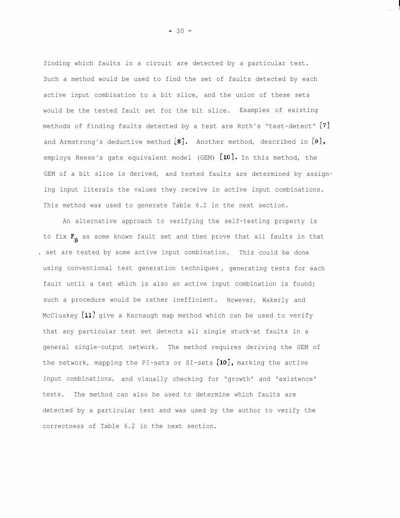
finding which faults in a circuit are detected by a particular test.
Such a method would be used to find the set of faults detected by each
active input combination to a bit slice, and the union of these sets
would be the tested fault set for the bit slice. Examples of existing
methods of finding faults detected by a test are Roth's "test-detect" [7]
and Armstrong's deductive method [B]. Another method, described in [9],
employs Reese's gate equivalent model (GEM) [lo]. In this method, the
GEM of a bit slice is derived, and tested faults are determined by assign-
ing input literals the values they receive in active input combinations.
This method was used to generate Table 6.2 in the next section.
An alternative approach to verifying the self-testing property is
to fix FB as some known fault set and then prove that all faults in that
. set are tested by some active input combination. This could be done
using conventional test generation techniques , generating tests for each
fault until a test which is also an active input combination is found;
such a procedure would be rather inefficient. However, Wakerly and
McCluskey [ll] give a Karnaugh map method which can be used to verify
that any particular test set detects all single stuck-at faults in a
general single-output network. The method requires deriving the GEM of
the network, mapping the PI-sets or SI-sets [lo], marking the active
input combinations, and visually checking for "growth" and "existence"
tests. The method can also be used to determine which faults are
detected by a particular test and was used by the author to verify the
correctness of Table 6.2 in the next section.
- 31 -t
LPi:I,
LI
L
i
c
i
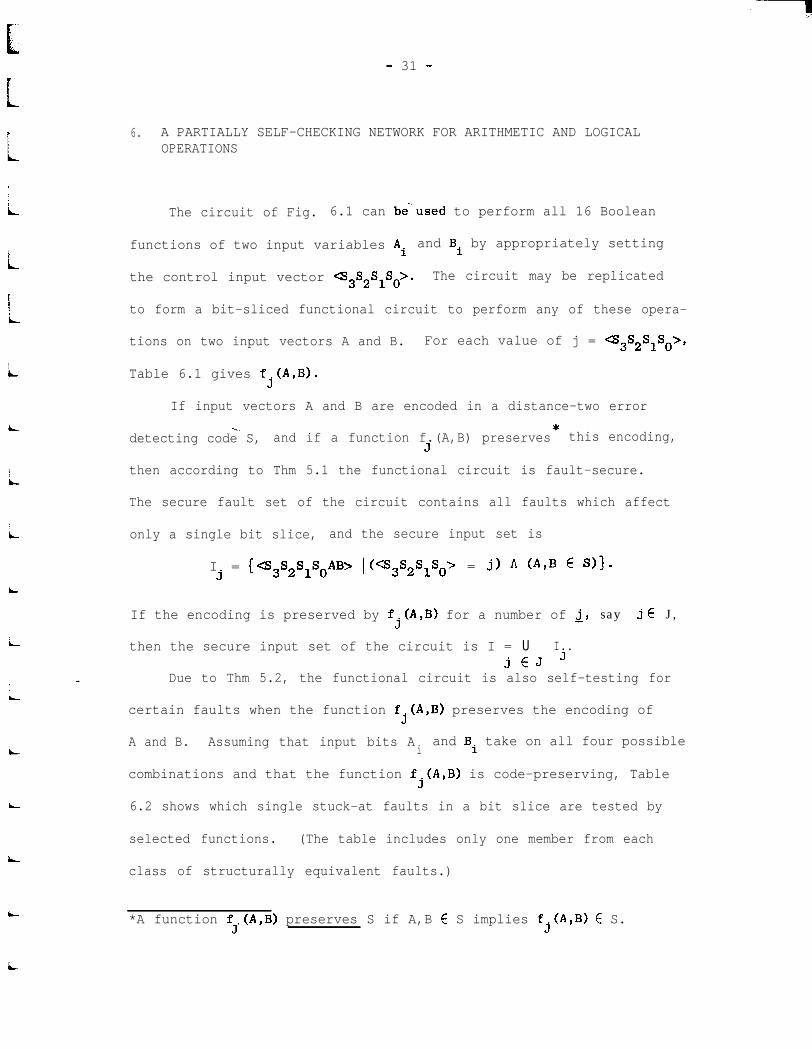
6. A PARTIALLY SELF-CHECKING NETWORK FOR ARITHMETIC AND LOGICALOPERATIONS
The circuit of Fig. 6.1 can be“used to perform all 16 Boolean
functions of two input variables Ai and Bi by appropriately setting
the control input vector 4S3S2SlSo>. The circuit may be replicated
to form a bit-sliced functional circuit to perform any of these opera-
tions on two input vectors A and B. For each value of j = <s3S2SlSo>,
Table 6.1 gives fj(A,B).
If input vectors A and B are encoded in a distance-two error
-=. *detecting code S, and if a function f.(A,B) preserves this encoding,
3
then according to Thm 5.1 the functional circuit is fault-secure.
The secure fault set of the circuit contains all faults which affect
only a single bit slice, and the secure input set is
I =3
(<s3s2SlSOA~> 1 ws3s2s1so~ = j) A (A$ E S)l-
i
i
iL
i
If the encoding is preserved by fj(A,B) for a number of 2, say j E J,
then the secure input set of the circuit is I = U I..jEJ J
Due to Thm 5.2, the functional circuit is also self-testing for
certain faults when the function fj(A,B) preserves the encoding of
A and B. Assuming that input bits Aiand Bi take on all four possible
combinations and that the function fj(A,B) is code-preserving, Table
6.2 shows which single stuck-at faults in a bit slice are tested by
selected functions. (The table includes only one member from each
class of structurally equivalent faults.)
*A function f.(A,B) preserves S if A,B E S implies fj(A,B) E S.3
i

r
- 32 -
s2 -
s1 -
so -
Fig. 6.1 Bit slice to perform any logic function of two variables
- 33 -
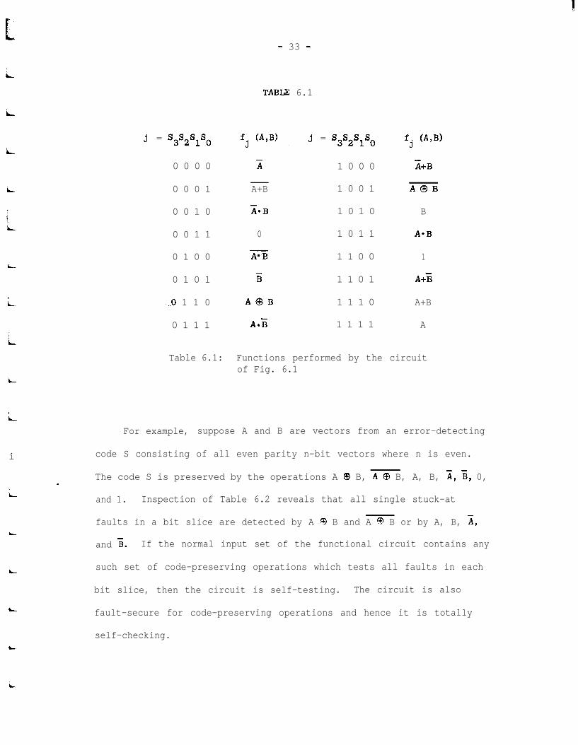
TABLIZ 6.1
j = s3s2s1so
L
i
c,i
0 0 0 0
0 0 0 1
0 0 1 0
0 0 1 1
0 1 0 0
0 1 0 1
=,o 1 1 0
0 1 1 1
fj (A,@ j. . = s3s2s1so
x 1 0 0 0
A+B 1 0 0 1
LB 1 0 1 0
0 1 0 1 1
A’B 1 1 0 0
ii 1 1 0 1
A@B 1 1 1 0
AZ 1 1 1 1
fj C&B)
;;i+B
AOB
B
A*B
1
A+i
A+B
A
Table 6.1: Functions performed by the circuitof Fig. 6.1
L
i
i
i
i
For example, suppose A and B are vectors from an error-detecting
code S consisting of all even parity n-bit vectors where n is even.
The code S is preserved by the operations A @ B, A @ B, A, B, A, B, 0,
and 1. Inspection of Table 6.2 reveals that all single stuck-at
faults in a bit slice are detected by A 0 B and A 3 B or by A, B, A,
and 5. If the normal input set of the functional circuit contains any
such set of code-preserving operations which tests all faults in each
bit slice, then the circuit is self-testing. The circuit is also
fault-secure for code-preserving operations and hence it is totally
self-checking.
i

- 34 -
TABLE 6.2
stuck-at-0
fj (A,@
0
1
AQB
fj (A,B)
0
1
AQBe
AQB
A
B
x
ii
AmB
A A2
x x
X
x x
X
A Al B B4 So S1
x x
xx xx X
xx x X
X x x
x x X
x x
x x
A3 B B1
X
X x x
X
X
x x
S2” s3
x x
X
X
x x
X
X X X
stuck-at-l
P1
P2 P3 p4
x x
x x
x x
X X
x x x x
X X
B3 B4
X
X
x x
X
B5 B6 '0
X
x x x
X X
X
X
X
x x
X
x x
X X
X X
x x x
x x
Table 6.2: Fault tests for the circuit of Fig. 6.1
c
i
- 35 -
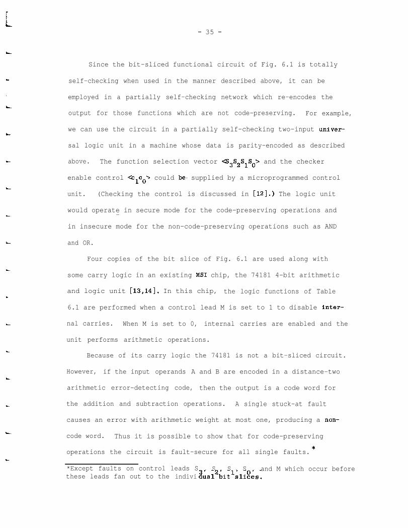
Since the bit-sliced functional circuit of Fig. 6.1 is totally
L’ self-checking when used in the manner described above, it can be
employed in a partially self-checking network which re-encodes the
output for those functions which are not code-preserving. For example,
we can use the circuit in a partially self-checking two-input univer-
sal logic unit in a machine whose data is parity-encoded as described
L- above. The function selection vector cS3S2SlSo> and the checker
L
enable control <clco) could be. supplied by a microprogrammed control
unit. (Checking the control is discussed in [12].) The logic unit
would operate in secure mode for the code-preserving operations and--
in insecure mode for the non-code-preserving operations such as AND
L and OR.
Four copies of the bit slice of Fig. 6.1 are used along with
some carry logic in an existing MS1 chip, the 74181 4-bit arithmetic
and logic unit [13,14]. In this chip, the logic functions of Table
6.1 are performed when a control lead M is set to 1 to disable inter-
nal carries. When M is set to 0, internal carries are enabled and the
unit performs arithmetic operations.
Because of its carry logic the 74181 is not a bit-sliced circuit.
However, if the input operands A and B are encoded in a distance-two
arithmetic error-detecting code, then the output is a code word for
the addition and subtraction operations. A single stuck-at fault
causes an error with arithmetic weight at most one, producing a non-
Lcode word. Thus it is possible to show that for code-preserving
*operations the circuit is fault-secure for all single faults.
*Except faults on control leads Ssi, S , S , S , and M which occur before
these leads fan out to the indivi ua12bit1sli!?es.
- 36 -
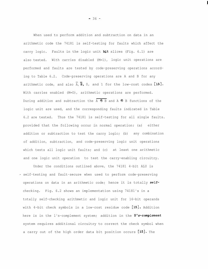
When used to perform addition and subtraction on data in an
arithmetic code the 74181 is self-testing for faults which affect the
carry logic. Faults in the logic unit b,it slices (Fig. 6.1) are
also tested. With carries disabled (M=l), logic unit operations are
performed and faults are tested by code-preserving operations accord-
ing to Table 6.2. Code-preserving operations are A and B for any
arithmetic code, and also A,- B, 0, and 1 for the low-cost codes [15].
With carries enabled (M=O), arithmetic operations are performed.
During addition and subtraction the A Q B and A @ B functions of the
logic unit are used, and the corresponding faults indicated in Table
6.2 are tested. Thus the 74181 is self-testing for all single faults.
provided that the following occur in normal operation: (a) either
addition or subtraction to test the carry logic; (b) any combination
of addition, subtraction, and code-preserving logic unit operations
which tests all logic unit faults; and (c) at least one arithmetic
and one logic unit operation to test the carry-enabling circuitry.
Under the conditions outlined above, the 74181 4-bit ALU is
- self-testing and fault-secure when used to perform code-preserving
operations on data in an arithmetic code; hence it is totally self-
checking. Fig. 6.2 shows an implementation using 74181's in a
totally self-checking arithmetic and logic unit for 16-bit operands
with 4-bit check symbols in a low-cost residue code [15]. Addition
here is in the l's-complement system; addition in the 2's-complement
system requires additional circuitry to correct the check symbol when
a carry out of the high order data bit position occurs [15]. The

- 37 -
functional circuit can be employed in a partially self-checking network
which performs non-code-preserving operations in insecure mode.
Td15-12
Td11-8
Td7-4
Td3-0
n
Co 74181 ci
Ad Bd15-12 15-12
-co 74181 ci-
J
MS3S2SlS0
Fig. 6.2 Partially self-checking ALU using 74181 4-bit ALU chips
- 38 -
7. OTHER APPLICATIONS
An existing use of the partially self-checking concept is in. .
arithmetic processors for addition, subtraction, and iterative
algorithms such as multiplication and division. If data is encoded
in an arithmetic code, then the adder circuit is self-testing and
fault-secure for the addition and subtraction operations. However,
during iterative operations the checker may be disabled until the
end to increase speed, and undetected errors due to repeated use
faults [15] can occur. Thus the arithmetic processor is partially---.
self-checking, operating in secure mode for addition and subtraction
and in insecure mode for the iterative algorithms.
Any totally self-checking functional circuit may be incorpora-
ted in a partially self-checking network. Such a network is useful
if in addition to secure mode the functional circuit has a useful mode
of operation in which the output is not a code word.

L
-
- 39 -
8. CONCLUSION
i
L
L
Several techniques are available for providing fault-detection
in fault-tolerant computers. In simple systems duplication and
matching might be the most inexpensive method because it requires the
least control circuitry and the least design effort. However, in
systems with a large number of fast registers which must be checked,
or in systems which are to be made as small as possible for LSI
implementation, the use of error-detecting codes is the most inexpen-
sive means of fault-detection. Unfortunately, there is no simple code
for checking logical operations such as AND and OR, and previous sys-
tems using coding have resorted to duplication for these operations.
In this report we have developed a theory of partially self-checking
circuits, and shown how partially self-checking networks may be used
to perform logical operations. The use of partially self-checking
networks is a low-cost method of performing these operations in
systems employing error-detecting codes for checking arithmetic and
data transfer operations.
L
L

9. mFERENCES
- 40 -
Cl1
r21
C3l
r41
L-51
bl
L-71
b1L
i
c.
bl
ho1
Cl11
Cl21
Carter, W. C., and P. R. Schneider, "Design of dynamicallychecked computers," IFIP 68;' vol. 2. Edinburg, Scotland,pp. 878-883, Aug. 1968.
Anderson, D. A., "Design of self-checking digital networksusing coding techniques," Coordinated Sci. Lab., Univ.Illinois, Urbana, Rep. R-527, Sept. 1971.
Carter, W. C., K. A. Duke, and D. C. Jessep, "A simple self-testing decoder checking circuit," IEEE Trans. Comput.,vol. c-20, pp. 1413-1414, Nov. 1971.
Peterson, W. W., and M. 0. Rabin, "On codes for checkinglogical operations," IBM Journal, vol. 3, pp. 163-168, Apr.1959.
Avizienis, A., et. al., "The STAR (self-testing and repairing)computer: An investigation of the theory and practice of fault-tolerant computer design," IEEE Trans. Camput., vol. C-20,PP. 1312-1321, Nov. 1971.
Rae, T. R. N., and P. Monteiro, "A residue checker for arith-metic and logical operations," Dig. 1972 Int'l. Symp. Fault-Tolerant Computing, pp. 8-13, June 1972.
Roth, J. P. et. al., "Programmed algorithms to compute teststo detect and distinguish between failures in logic circuits,"IEEE Trans. Electron. Comput., vol. EC-16, pp. 567-580, Oct.1967.
Armstrong, D. B., "A deductive method for simulating faults inlogic networks," IEEE Trans. Comput., vol. C-21, pp. 464-471,May 1972.
Wakerly, J. F., "A method of finding faults detected by testsusing the GEM," Dig. Syst. Lab., Stanford,Calif., Tech. Note 31,August 1973.
Reese, R. D., and E. J. McCluskey, "A gate equivalent model forcombinational logic network analysis," Dig. 1973 Int'l. Symp.Fault-Tolerant Computing, June 1973.
Wakerly, J. F., and E. J. McCluskey, "A graphical method ofidentifying fault tests in combinational logic networks," Dig.Syst. Lab., Stanford,Calif., Tech. Rep. 66, August 1973.
Wakerly, J. F. "Low-cost error detection techniques for smallcomputers," Dig. Syst. Lab., Stanford,Calif., Tech. Rep. 51 9Sept. 1973.

- 41 -
[13] Fairchild 9341/54181, 74181 data sheet.
[14] Signetics S54181/N74181 data sheet.
[15] Avizienis, A., "Arithmetic codes: Cost and effectivenedsstudies for applications in digitai‘ systems design," IEEE Trans.Comput., vol. C-20, pp. 1322-1331, NOV. 1971.