particle characterization needs – a nanocomposite...
TRANSCRIPT

Particle Characterization Needs –A Nanocomposite Perspective
Dr. Lee A. Silverman
DuPont Nanocomposite Technologies, Central Research and Development
Wilmington, Delaware 19880

2
Textured Surfaces: (Physically Patterned or textured on the nanoscale)
Levels of Nanoscale
Design
Surface Films(Nanoscale in surface thickness only)
Nano Particles(nanoscale in one or more dimensions)
50 nm50 nm
Nanodevices
Nanostructured bulk materials(nanoscale internal structure)
Partitioning Nanotechnology Space

3
Nanomaterials – An Enabling Technology
Manipulation of materials on very fine scale is broadly useful across polymer platforms
Desired property combinations can be achieved with proper selection of materials and microstructure
Examples• Rheology and mechanical
• Barrier and optical
• Thermal and surface roughness
Rheological
Optica
l
Electrical
Therm
al
Surf
ace
Barrier
ElectronicM
echanical
Unique Unique CombinationsCombinations

4
Particle Dimensionality Defines Properties
plates
rods
spheres
Barrier, thermomechanical, flame retardancy, CTE in plane, very high interfacial area
electrical conductivity, themomechanical, network structures, fillers for fibers
Isotropy, transparency, electronic, magnetic, photonic, model systems
Properties/uses

5
Nanoparticles Polymers
Polyimide
Fluoropolymers
Thermoset
Polyamide
Polyester
Polyolefins
Ionomers
Others…
Dispersion & Compatibilization
TiO2, SiO2, BaTiO3, AlN, diamonds, Q-dots, polymers…
CNT, Al2O3, SiC, TiO2tubes….
Clay, exfoliated graphite..
Interfacial Chemistry• Surfactants• Coupling agents
Structures & Interphase• Dendrimers• Multiblock polymers• Flexible links
Process Technology• Polymer processing• Milling/grinding• Particle
formation/modification
Nanocomposite Systems Require Compatible Particles, Polymers and Processes

6
High Loadings Complicate Characterization
Silica in polystyrene (10%)
0.0
0.5
1.0
1.5
2.0
2.5
0.00 0.02 0.04 0.06 0.08 0.10 0.12 0.14
q (1/A)
S(q)
50 v% 40 v% 30 v% 20 v% 10 v%
SAXS Data
Fits hard sphere model
7
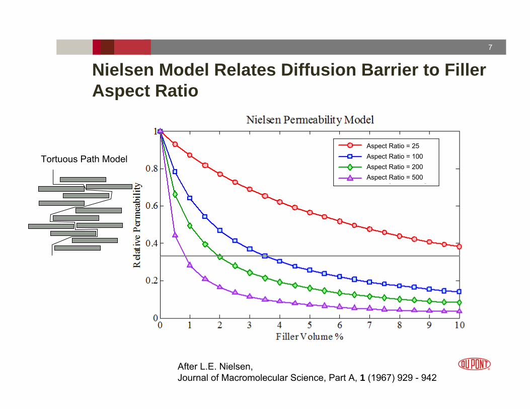
Nielsen Model Relates Diffusion Barrier to Filler Aspect Ratio
Aspect Ratio = 25Aspect Ratio = 100Aspect Ratio = 200Aspect Ratio = 500
Tortuous Path Model
After L.E. Nielsen, Journal of Macromolecular Science, Part A, 1 (1967) 929 - 942

8
Garboczi Model Relates Percolation Threshold to Ellipsoid Aspect Ratio
Pc ≡ critical volume fraction for percolation
E.J. Garboczi, et. al., Physical Review E, 52 (1995) 819-828

9
Graphene/Polystyrene Composite Electrical Conductivity
S. Stankovich, et. al., Nature 442 (2006) 282-286

10
Gao Model Relates Thermal Conductivity vs. Aspect Ratio
L. Gao, et. al.,Chemical Physics Letters, 434 (2007) Pages 297-300
Volume fraction = 0.05Kp/Km = 1000Contact resistance = 0
Ke/K
m
25
20
15
10
5
010-3 10-2 10-1 100 101 102 103
Aspect Ratio
11
Surlyn 8945 Ec/E0 vs. MMT modifier, Concentration & Ar (aligned)
1.0
1.5
2.0
2.5
3.0
3.5
4.0
4.5
0.0% 1.0% 2.0% 3.0% 4.0% 5.0% 6.0% 7.0% 8.0% 9.0% 10.0%Filler Concentration (wt %)
Rel
ativ
e M
odul
us E
c/E0
l/h = 100.0l/h = 30.0l/h = 20.08945/20A8945/6A8945/93ANeut./20ANeut./6A
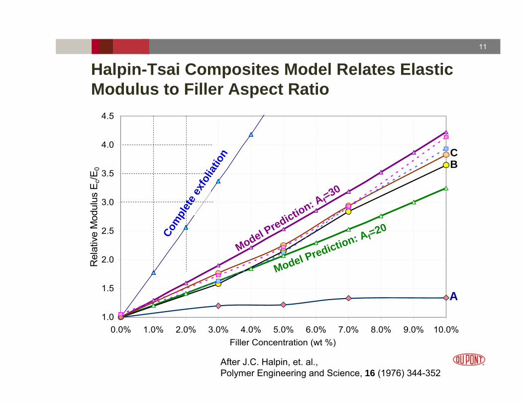
Halpin-Tsai Composites Model Relates Elastic Modulus to Filler Aspect Ratio
A
BC
Model Prediction: A f=30
Model Prediction: Af=20Com
plet
e exf
oliat
ion
After J.C. Halpin, et. al.,Polymer Engineering and Science, 16 (1976) 344-352

12
Environmental, Health and Safety, and Product Stewardship“All fiber types capable of depositing in the thorax are not alike in their pathogenic potential…
A complete characterization (i.e., dimensions, fiber number, mass, and aerodynamic diameter) of the fiber aerosol and retained dose is essential.”
• R. McClellan, et. al. – Regul Toxicol Pharmacol, 16 (1992) 321-64
“A robust structure/activity paradigm has emerged from (research on fibre toxicology) that highlights fibre length, thinness, and biopersistence as major factors in determining the pathogenicity of a fibre.”
• K. Donaldson, Crit. Rev. Toxicol. 39 (2009) 487-500
DuPont’s stewardship process requires extensive characterization
• www.nanoriskframework.com

13
How Should We Determine Particle Size (<100nm)
Scanning Electron Microscopy (SEM)
RodsSpheresPlates
Dry/Solvent Dispersed CompositeMethod
Scanning Probe Microscopy (SPM)
Static Light Scattering (SLS)
Small Angle X-ray Scattering (SAXS)
Transmission Electron Microscopy (TEM)
Dynamic light scattering (DLS)
RodsSpheresPlates
= highly oriented

14
PMMA/Clay Composite
5 v% clay in PMMA

15
How Should We Determine Particle Size (<100nm)
Re-entrant
Multi-modal
FacetedDistri-bution
Surface Area (BET)
Scanning Electron Micr. (SEM)
RodSpherePlate
CompositeMethod
Scanning Probe Micr. (SPM)
Static Light Scattering (SLS)
Small Angle X-ray Scattering (SAXS)
Transmission Electron Micr. (TEM)
Dynamic light scattering (DLS)
= specially oriented

16
SummaryParticle size, shape, distribution critical in nanocomposites
• Property entitlement• EHS and product stewardship
We know how to characterize monodisperse spherical systems!Characterization of platy and rod-like particles onerous at best
• Highly oriented systems• Low particle concentrations
Characterization almost impossible in composites• Size distributions (especially multimodal)• Faceted particles• Highly irregular particles (especially re-entrant shapes)• High loadings
Surface chemistry is very important also• But is the subject of another (lengthy) discussion