particle coating in fluidized beds
TRANSCRIPT

Particle Coating in Fluidized BedsMohammad Foroughi-Dahr, Navid Mostoufi, and Rahmat Sotudeh-Gharebagh, University of Tehran, Tehran, IranJamal Chaouki, Ecole Polytechnique de Montreal, Montreal, QC, Canada
ã 2017 Elsevier Inc. All rights reserved.
Introduction 2Fundamentals of the Coating Process 2Objective of Coating 3Coating Applications 3Coating Solution 4Solvent 4Polymer 4Plasticizer 5Colorant/Opacifier 5Antitack Agent 5Different Methods of Coating of Particles 6Melt Coating 6Supercritical Fluid Coating 6Compression Coating 6Spray Drying Coating 6Pan coating 6Air suspension coating 6Top-Spray Fluidized Bed 7Tangential-Spray Fluidized Bed 8Bottom-Spray Fluidized Bed (Wurster) 8Upbed Region 9Expansion Region 10Downbed Region 10Horizontal Transport Region 10Coating Life cycle in a Spray Fluidized Bed 11Particle Movement 11Atomization 11Wetting the Particle Surfaces 12Droplet–particle impact 12Droplet spreading and adherence on the particle surface 13Drying and Film Formation 14Conclusion 14References 14
Re
NomenclatureC0 Initial moisture content, kg water/kg dry solid
Ct Moisture content at any time t, kg water/kg
dry solid
Ce Moisture content at equilibrium, kg water/kg
dry solid
d0 Initial droplet diameter, m
dt Droplet diameter at any time t, m
dd The mean diameter of droplets, mmdp The particle diameter, m
dVM, solution Volume mean droplet diameters of
solution, m
dVM, solvent Volume mean droplet diameters of solvent, m
Deff Effective moisture diffusivity, m2s�1
g Gravity acceleration, m s�1
k Thermal conductivity of fluidized air,
W m�1K�1
ference Module in
Chemistry, Molecular Sciences and Chemical Engineering httpMCP Weight of the coated particles, g
MUP Weight of the uncoated particles, g
MCM Weight of the coat material sprayed into the
coater, g
Pat Atomization pressure, bar
R Droplet radius, m
teva The evaporation time, s
Tbed Bed temperature, �CTinlet Inlet air temperature, �CDT Difference between the air temperature and
droplet surface temperature, K
Usol Fluid volumetric flow rate, m3s�1
Uat Air volumetric flow rate, m3s�1
vREL Outlet air velocity (the velocity of air relative
to liquid at the atomizer nozzle exit), m s�1
wm Necessary work of wetting per unit area, J m�2
Y Coating yield
://dx.doi.org/10.10
16/B978-0-12-409547-2.12206-1 1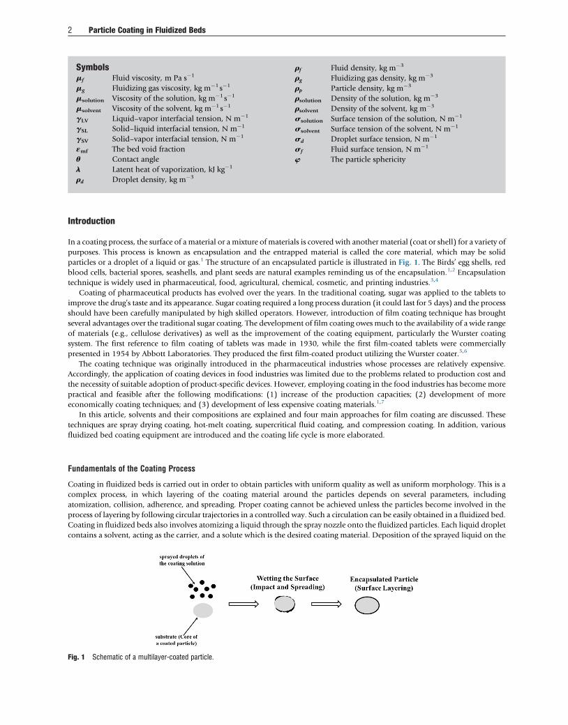
Fi
2 Particle Coating in Fluidized Beds
Symbolsmf Fluid viscosity, m Pa s�1
mg Fluidizing gas viscosity, kg m�1s�1
msolution Viscosity of the solution, kg m�1 s�1
msolvent Viscosity of the solvent, kg m�1 s�1
gLV Liquid–vapor interfacial tension, N m�1
gSL Solid–liquid interfacial tension, N m�1
gSV Solid–vapor interfacial tension, N m�1
«mf The bed void fraction
u Contact angle
l Latent heat of vaporization, kJ kg�1
rd Droplet density, kg m�3
g. 1 Schem
atic of a multilayer-coated particle.rf Fluid density, kg m�3
rg Fluidizing gas density, kg m�3
rp Particle density, kg m�3
rsolution Density of the solution, kg m�3
rsolvent Density of the solvent, kg m�3
ssolution Surface tension of the solution, N m�1
ssolvent Surface tension of the solvent, N m�1
sd Droplet surface tension, N m�1
sf Fluid surface tension, N m�1
w The particle sphericity
Introduction
In a coating process, the surface of amaterial or a mixture of materials is covered with another material (coat or shell) for a variety of
purposes. This process is known as encapsulation and the entrapped material is called the core material, which may be solid
particles or a droplet of a liquid or gas.1 The structure of an encapsulated particle is illustrated in Fig. 1. The Birds’ egg shells, red
blood cells, bacterial spores, seashells, and plant seeds are natural examples reminding us of the encapsulation.1,2 Encapsulation
technique is widely used in pharmaceutical, food, agricultural, chemical, cosmetic, and printing industries.3,4
Coating of pharmaceutical products has evolved over the years. In the traditional coating, sugar was applied to the tablets to
improve the drug’s taste and its appearance. Sugar coating required a long process duration (it could last for 5 days) and the process
should have been carefully manipulated by high skilled operators. However, introduction of film coating technique has brought
several advantages over the traditional sugar coating. The development of film coating owes much to the availability of a wide range
of materials (e.g., cellulose derivatives) as well as the improvement of the coating equipment, particularly the Wurster coating
system. The first reference to film coating of tablets was made in 1930, while the first film-coated tablets were commercially
presented in 1954 by Abbott Laboratories. They produced the first film-coated product utilizing the Wurster coater.5,6
The coating technique was originally introduced in the pharmaceutical industries whose processes are relatively expensive.
Accordingly, the application of coating devices in food industries was limited due to the problems related to production cost and
the necessity of suitable adoption of product-specific devices. However, employing coating in the food industries has become more
practical and feasible after the following modifications: (1) increase of the production capacities; (2) development of more
economically coating techniques; and (3) development of less expensive coating materials.1,7
In this article, solvents and their compositions are explained and four main approaches for film coating are discussed. These
techniques are spray drying coating, hot-melt coating, supercritical fluid coating, and compression coating. In addition, various
fluidized bed coating equipment are introduced and the coating life cycle is more elaborated.
Fundamentals of the Coating Process
Coating in fluidized beds is carried out in order to obtain particles with uniform quality as well as uniform morphology. This is a
complex process, in which layering of the coating material around the particles depends on several parameters, including
atomization, collision, adherence, and spreading. Proper coating cannot be achieved unless the particles become involved in the
process of layering by following circular trajectories in a controlled way. Such a circulation can be easily obtained in a fluidized bed.
Coating in fluidized beds also involves atomizing a liquid through the spray nozzle onto the fluidized particles. Each liquid droplet
contains a solvent, acting as the carrier, and a solute which is the desired coating material. Deposition of the sprayed liquid on the

Particle Coating in Fluidized Beds 3
fluidized particles follows a life cycle with different steps in order to attain a successful coating. Atomized by the nozzle, the droplets
come into contact with the particles. After the impact and coherence of the droplets onto the particles, the droplets spread on the
surface. Solvent is then evaporated, which leads to the formation of a thin, uniform layer of solute around the particles. Complete
coverage of the surface is achieved during several passes of particles through the coating zone.8,9
Objective of Coating
The objective of the coating process is to obtain coated particles with an appropriate and standard quality as well as reproducible
products. The coating quality may be characterized based on both uniformity of the coating mass and coating morphology. The
coating mass uniformity describes the variation in the amount of coating material deposited on each product particle, while the
coating morphology can be ascribed to the variation of a given property of the finished particles with the same amount of coating
material.10 Quality of the coated product may be assessed based on two approaches, namely, macroscopic and microscopic.
The microscopic quality evaluation of the coating is related to the quality of the coating materials deposited on each particle.
This coating quality depends on the product application. For example, if the retarding potential of the final product is important, a
constant coating thickness across the surface of the particles would be required. Also, no holes should be found on the coated
surface. However, in the case of coloring the food, it may be credible to have an uneven coated product with tiny holes on its
surface.
The kinetic release curve of the product demonstrates the quality of coating. For this purpose, the experiments should be
conducted using a specific amount of distilled water (e.g., 100 or 200 mL). The water is poured in a beaker and the desired amount
of coated product (e.g., 2 or 3 g) is added to it. The beaker is then shaken mildly and the concentration of solution is measured at
preset time intervals. In this way, the release curve of the coated product can be obtained. Examples of such curve are shown in
Fig. 2.4,11 Considering this figure, different coating qualities are classified in Table 1.
The macroscopic approach of evaluating the coating quality is focused on the coater performance based on product uniformity,
production yield, degree of agglomeration, and production time. The coating uniformity is evaluated by means of relative standard
deviation of thickness of the coat among individual particles.
The coating yield (%Y) is defined by the following equation:
%Y ¼ MCP�MUPð Þ�100=MCM (1)
where MCP and MUP stand for the weight of coated and uncoated particles (g), respectively, and MCM is the weight of the coat
material sprayed into the coater (g). Particle agglomerates are formed due to establishing liquid bridges between particles.
Generally, particle agglomeration is undesirable in the coating process and should be avoided by optimizing the process
parameters. The degree of agglomeration is defined as the ratio of the mass of particle agglomerates to the total mass of particles.
The mass of the particle agglomerates can be obtained using a sieve with desired nominal opening size larger than the maximum
limit value of the coated particle. The optimum operation in the coating process can be achieved when more uniform coated
particle, higher production yield, and lower degree of agglomeration are achieved. Accordingly, lower amounts of coating material
are applied for a specific coating thickness and shorter production time is required.4,12,13
Coating Applications
Particle coating can be found in several industries, such as pharmaceutical, food, and agricultural. The coating process is conducted
for several reasons, depending on the usage of the final product. The main reasons are:
• To mask unpleasant taste of the substances14,15
• To increase the shelf life16,17
Fig. 2 Release behavior of active ingredients.
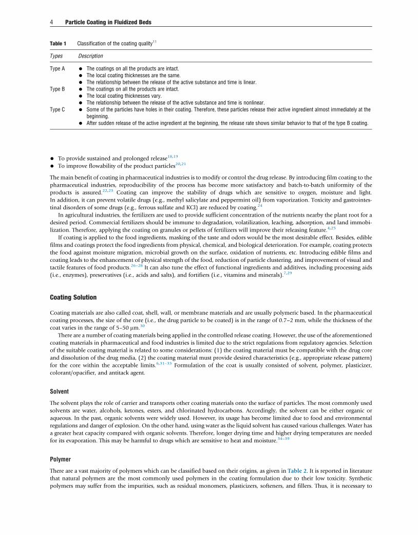
Table 1 Classification of the coating quality11
Types Description
Type A • The coatings on all the products are intact.
• The local coating thicknesses are the same.
• The relationship between the release of the active substance and time is linear.Type B • The coatings on all the products are intact.
• The local coating thicknesses vary.
• The relationship between the release of the active substance and time is nonlinear.Type C • Some of the particles have holes in their coating. Therefore, these particles release their active ingredient almost immediately at the
beginning.
• After sudden release of the active ingredient at the beginning, the release rate shows similar behavior to that of the type B coating.
4 Particle Coating in Fluidized Beds
• To provide sustained and prolonged release18,19
• To improve flowability of the product particles20,21
The main benefit of coating in pharmaceutical industries is to modify or control the drug release. By introducing film coating to the
pharmaceutical industries, reproducibility of the process has become more satisfactory and batch-to-batch uniformity of the
products is assured.22,23 Coating can improve the stability of drugs which are sensitive to oxygen, moisture and light.
In addition, it can prevent volatile drugs (e.g., methyl salicylate and peppermint oil) from vaporization. Toxicity and gastrointes-
tinal disorders of some drugs (e.g., ferrous sulfate and KCl) are reduced by coating.24
In agricultural industries, the fertilizers are used to provide sufficient concentration of the nutrients nearby the plant root for a
desired period. Commercial fertilizers should be immune to degradation, volatilization, leaching, adsorption, and land immobi-
lization. Therefore, applying the coating on granules or pellets of fertilizers will improve their releasing feature.4,25
If coating is applied to the food ingredients, masking of the taste and odors would be the most desirable effect. Besides, edible
films and coatings protect the food ingredients from physical, chemical, and biological deterioration. For example, coating protects
the food against moisture migration, microbial growth on the surface, oxidation of nutrients, etc. Introducing edible films and
coating leads to the enhancement of physical strength of the food, reduction of particle clustering, and improvement of visual and
tactile features of food products.26–28 It can also tune the effect of functional ingredients and additives, including processing aids
(i.e., enzymes), preservatives (i.e., acids and salts), and fortifiers (i.e., vitamins and minerals).7,29
Coating Solution
Coating materials are also called coat, shell, wall, or membrane materials and are usually polymeric based. In the pharmaceutical
coating processes, the size of the core (i.e., the drug particle to be coated) is in the range of 0.7–2 mm, while the thickness of the
coat varies in the range of 5–50 mm.30
There are a number of coating materials being applied in the controlled release coating. However, the use of the aforementioned
coating materials in pharmaceutical and food industries is limited due to the strict regulations from regulatory agencies. Selection
of the suitable coating material is related to some considerations: (1) the coating material must be compatible with the drug core
and dissolution of the drug media, (2) the coating material must provide desired characteristics (e.g., appropriate release pattern)
for the core within the acceptable limits.6,31–33 Formulation of the coat is usually consisted of solvent, polymer, plasticizer,
colorant/opacifier, and antitack agent.
Solvent
The solvent plays the role of carrier and transports other coating materials onto the surface of particles. The most commonly used
solvents are water, alcohols, ketones, esters, and chlorinated hydrocarbons. Accordingly, the solvent can be either organic or
aqueous. In the past, organic solvents were widely used. However, its usage has become limited due to food and environmental
regulations and danger of explosion. On the other hand, using water as the liquid solvent has caused various challenges. Water has
a greater heat capacity compared with organic solvents. Therefore, longer drying time and higher drying temperatures are needed
for its evaporation. This may be harmful to drugs which are sensitive to heat and moisture.34–39
Polymer
There are a vast majority of polymers which can be classified based on their origins, as given in Table 2. It is reported in literature
that natural polymers are the most commonly used polymers in the coating formulation due to their low toxicity. Synthetic
polymers may suffer from the impurities, such as residual monomers, plasticizers, softeners, and fillers. Thus, it is necessary to
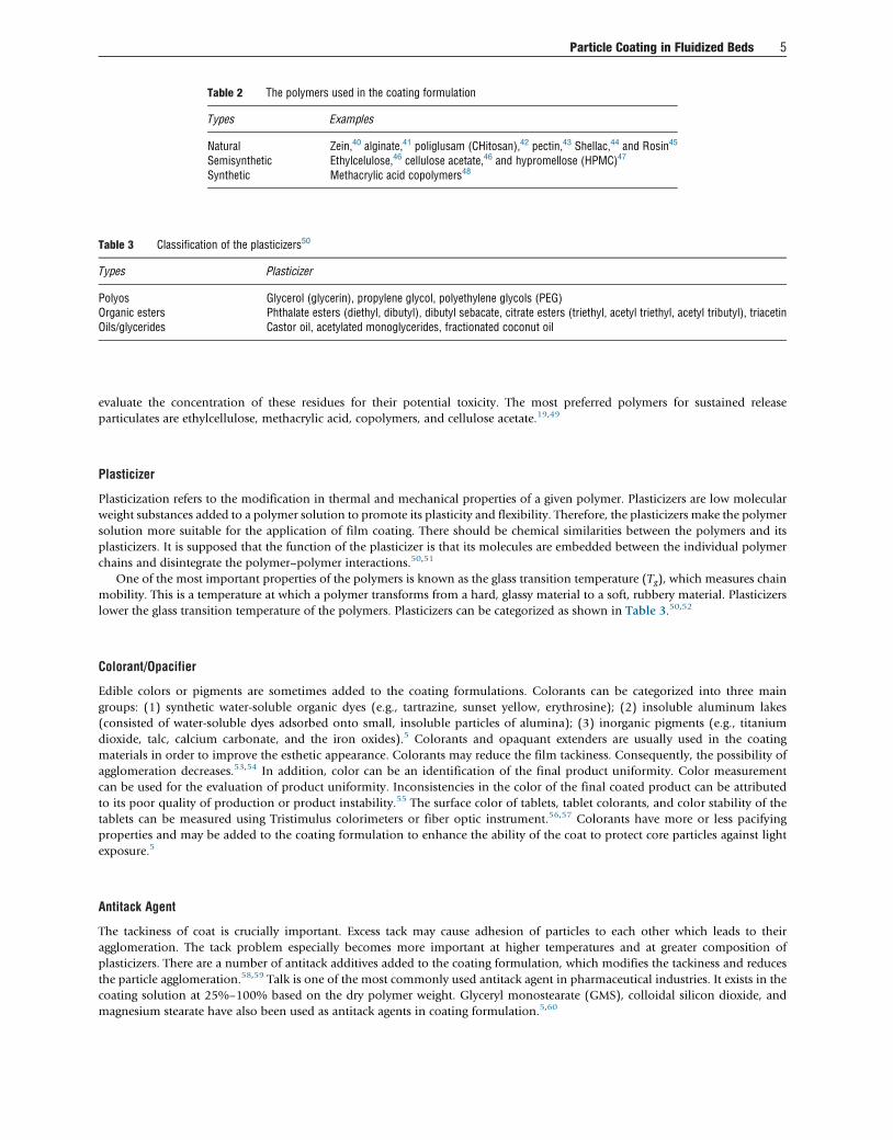
Table 2 The polymers used in the coating formulation
Types Examples
Natural Zein,40 alginate,41 poliglusam (CHitosan),42 pectin,43 Shellac,44 and Rosin45
Semisynthetic Ethylcelulose,46 cellulose acetate,46 and hypromellose (HPMC)47
Synthetic Methacrylic acid copolymers48
Table 3 Classification of the plasticizers50
Types Plasticizer
Polyos Glycerol (glycerin), propylene glycol, polyethylene glycols (PEG)Organic esters Phthalate esters (diethyl, dibutyl), dibutyl sebacate, citrate esters (triethyl, acetyl triethyl, acetyl tributyl), triacetinOils/glycerides Castor oil, acetylated monoglycerides, fractionated coconut oil
Particle Coating in Fluidized Beds 5
evaluate the concentration of these residues for their potential toxicity. The most preferred polymers for sustained release
particulates are ethylcellulose, methacrylic acid, copolymers, and cellulose acetate.19,49
Plasticizer
Plasticization refers to the modification in thermal and mechanical properties of a given polymer. Plasticizers are low molecular
weight substances added to a polymer solution to promote its plasticity and flexibility. Therefore, the plasticizers make the polymer
solution more suitable for the application of film coating. There should be chemical similarities between the polymers and its
plasticizers. It is supposed that the function of the plasticizer is that its molecules are embedded between the individual polymer
chains and disintegrate the polymer–polymer interactions.50,51
One of the most important properties of the polymers is known as the glass transition temperature (Tg), which measures chain
mobility. This is a temperature at which a polymer transforms from a hard, glassy material to a soft, rubbery material. Plasticizers
lower the glass transition temperature of the polymers. Plasticizers can be categorized as shown in Table 3.50,52
Colorant/Opacifier
Edible colors or pigments are sometimes added to the coating formulations. Colorants can be categorized into three main
groups: (1) synthetic water-soluble organic dyes (e.g., tartrazine, sunset yellow, erythrosine); (2) insoluble aluminum lakes
(consisted of water-soluble dyes adsorbed onto small, insoluble particles of alumina); (3) inorganic pigments (e.g., titanium
dioxide, talc, calcium carbonate, and the iron oxides).5 Colorants and opaquant extenders are usually used in the coating
materials in order to improve the esthetic appearance. Colorants may reduce the film tackiness. Consequently, the possibility of
agglomeration decreases.53,54 In addition, color can be an identification of the final product uniformity. Color measurement
can be used for the evaluation of product uniformity. Inconsistencies in the color of the final coated product can be attributed
to its poor quality of production or product instability.55 The surface color of tablets, tablet colorants, and color stability of the
tablets can be measured using Tristimulus colorimeters or fiber optic instrument.56,57 Colorants have more or less pacifying
properties and may be added to the coating formulation to enhance the ability of the coat to protect core particles against light
exposure.5
Antitack Agent
The tackiness of coat is crucially important. Excess tack may cause adhesion of particles to each other which leads to their
agglomeration. The tack problem especially becomes more important at higher temperatures and at greater composition of
plasticizers. There are a number of antitack additives added to the coating formulation, which modifies the tackiness and reduces
the particle agglomeration.58,59 Talk is one of the most commonly used antitack agent in pharmaceutical industries. It exists in the
coating solution at 25%–100% based on the dry polymer weight. Glyceryl monostearate (GMS), colloidal silicon dioxide, and
magnesium stearate have also been used as antitack agents in coating formulation.5,60

6 Particle Coating in Fluidized Beds
Different Methods of Coating of Particles
There are several techniques for coating of materials. These techniques can basically be categorized as melt coating, supercritical
fluid coating, compression coating, and spray drying coating. These coating techniques are further described as follows.
Melt Coating
If melting point of the coating material is low, the coating material could be used in the molten state and the melt coating
technique can be applied. It is recommended to use a product bed temperature of up to 140–150�C in order to have physically
and chemically stable materials. Moreover, the melting point of the coating material should be less than 80�C. The coating
materials used in this method are usually derived from plants or animals, including hydrogenated vegetable oil (e.g., cotton
seed oil, palm oil, and soy bean oil), carnauba wax, and glyceride. Fluidized bed coaters are the commonly used equipment in
this technique.61–65
Supercritical Fluid Coating
Application of the supercritical fluid coating method in the coating of particles is limited. In this technique, the solid coating
material is suspended in a supercritical fluid. Carbon dioxide is the most used supercritical solvent in this case. In fact, supercritical
carbon dioxide is the medium used for reducing the viscosity in order to spray the coating materials onto the particles. The coating
material should have adequate solubility in the supercritical carbon dioxide. Such materials include lipids, fatty alcohols, fatty
acids, fats, waxes, Eudragit polymers, triglycerides of myristic acid, glycerides and glyceride ester of polyethylene glycol, trimyristin,
Myvacct, octadecanol, cholesterol, and lecithin.66–69
Compression Coating
In this method, the coating material is compressed around a core (i.e., particle) using a special tablet press. This method is mostly
used for larger particles. In the compression coating method, first, the drug materials are compressed into the shape of a tablet (i.e.,
the drug is in the core). Afterward, the core is placed in a die of a tablet with the half of the coating material. Subsequently, the core
is surrounded with the remainder coating material which forms the outer coating layer. Finally, it is compressed by punch to
become a coated particle. The compression coating is not a commonly used process because of some deficiencies. For example, if
the core is not placed in the center of the die, this may result in an incomplete coating. The coating materials in this technique
include polyethylene oxide, polyethylene glycol, hydrogenated castor oil, cellulose derivatives, complex of alginate-chitosan,
sodium alginate, and behenic acid.6,70–74
Spray Drying Coating
In the spray drying method, a solution is sprayed by a nozzle into a bed of particles. Layers of the coating material are formed after
evaporation of the solution. Different polymers are used in this method, including Eudragits, shellac, and ethyl cellulose.75–77 The
equipment used for this purpose are pan coater and air suspension coaters, including top spray fluidized bed, tangential spray
fluidized bed, and bottom spray fluidized bed. These air suspension coaters are the most common equipment for coating
applications in food and pharmaceutical industries.76,78–81
Pan coatingThe first pan coaters were employed for sugar coating of tablets which was borrowed from the confectionary industry. The open,
copper, bowl-shaped, pan coaters were widely used in the pharmaceutical industries which are now substituted with stainless steel
ones. Conventional pan coaters rotate at an angle of about 45� to the horizontal at a speed range of 20–50 rpm. The conventional
pan coater suffers from the inconvenient heat transfer between the drying air and the particle bed. In addition, it is a lengthy process
and requires skilled operators. However, the basic pan coaters have been improved by a number of modifications including:
(1) application of side air exhaustion (improving the drying capacity), (2) installation of the perforated distribution plate, and
(3) implementation of different shaped pans (cylindrical, hexagonal, and pear shaped).6,35,36
Air suspension coatingApplying modifications to the pan coating system led to the introduction of a new coating technique, the air suspension coating
technique. The basic fundamental characteristic corresponding to air suspension coaters is the fluidization of particles upwardly.
Injecting the fluidization gas causes the particle circulation throughout the chamber. Accordingly, formation of agglomerates may
be controlled more properly and a product with more superior quality can be obtained.6,10,82
This technique has great advantages over other conventional coating systems due to the high heat and mass transfer rates.
Accordingly, there exist uniform temperature distribution and relatively short coating time in fluidized beds. This technique is one
of the most preferred methods of particle coating due to producing high quality product, possibility of multilayer coating, and its

Particle Coating in Fluidized Beds 7
capability of large-scale production. Moreover, fluidized beds are used for granulation processes and are the most preferable
equipment for this purpose because of short processing time and easiness of operation.6,64,83,84 The coating material is atomized
from a spray nozzle. The spray nozzle may be located at different positions, such as at top of the particle container in the top spray
fluidized bed coater, at the bottom of the particle container in the bottom spray fluidized bed coater, or on the side of the particle
container in the tangential spray fluidized bed coater. The air suspension coating technique is explained more thoroughly in the
proceeding sections.
Top-Spray Fluidized Bed
The top-spray fluidized bed is known to be the simplest one among the spray fluidized beds. It has evolved from commercial
fluidized bed dryers and provides a high capacity and low capital cost. The spray nozzle is placed at the top of the coating chamber.
Coating materials are countercurrently sprayed at a low pressure and sheared onto the fluidized particles. The spray nozzle is
typically a binary or pneumatic nozzle. The volume capacity of the apparatus is in the range of 2 L (lab scale) to more than
2000 L.85–87 Schematic of the top spray fluidized bed is shown in Fig. 3.
The fluidizing gas is blown from the bottom of the chamber through the gas distributor plate and fluidizes the substrates.
At lower fluid velocities, the bed remains static. As the air velocity is increased, an abrupt change of the substrates is observed which
is called minimum or incipient fluidization. From the fixed bed conditions, the minimum fluidization velocity can be theoretically
calculated using Carman–Kozeny equation88:
umf ¼’dp� �2180
rp�rg� �
g
mg
e3mf
1� emf
!(2)
where ’, dp, and rp denote the particle sphericity, the particle diameter (m), and the particle density (kg m�3), respectively; rg andmg are the fluidizing gas density (kg m�3) and fluidizing gas viscosity (kg m�1 s�1); g is gravity acceleration (m s�1); and emf
represents the bed void fraction at this condition.
Fig. 3 Schematic of the top-spray fluidized bed coater.

8 Particle Coating in Fluidized Beds
At the minimum fluidization, the velocity of the substrates is very low, which may not be economically practical and promote
agglomeration.82,89,90 For this purpose, the top-spray coating fluidized beds operate in the bubbling fluidization regime. According
to Fig. 3 the substrates are randomly exposed to the sprayed coating material, after which the coated substrates pass the coating
zone into the expansion zone. Evaporating the coating solvent from the surface in the expansion zone, the coated substrates fall
back into the product container.82,90
Moving randomly and unrestrictedly, the particles circulate in a less ordered pattern in the top-spray fluidized bed. Accordingly,
the travel distance of droplets cannot be controlled prior to its contact with the substrate surface. As a result, the droplets may
become dried prematurely which is considered as the main drawback of the top-spray fluidized beds. As a result, the top-spray
fluidized bed is improper equipment for the film coating and controlled release coating of particulates. However, it is more
common to utilize the top-spray fluidized bed for the aim of taste masking, barrier coating, cosmetic coating, and functional
coating.10,86
This process has the most possibility of being used in food industries as compared with the other air suspension coating
methods in order to further enhance the shelf life (i.e., allowing a longer period of storage against moisture, oxygen, and light).
Top-spray fluidized bed is considered to be more feasible for food industry mainly because of its high versatility, relatively large
batch size, and simplicity.7,31 It should be noted that the top-spray fluidized beds offer the best results in the case of hot-melting
coating when compared with the tangential-spray and bottom-spray coaters. This is due to the fact that the product container of the
top spray fluidized bed is designed for an unrestricted particle flow, the principle which is one of the most important features of the
hot-melt coating.91–94
Tangential-Spray Fluidized Bed
The tangential-spray fluidized bed is a relatively new fluidization technique for coating of particles. This approach takes advantage
of a rotating disk to provide a circular pattern for movement of particles. The disk is adjusted at a height to give a slit between the
edge of the disk and the wall of the coater chamber. The fluidizing gas passes upward through the annular space between the
periphery of the rotating disk and the wall. Exploiting the rotating disk and fluidizing gas, the tangential-spray fluidized bed can
process a large volume of solids in relatively small equipment. The spray nozzle is mounted at the side of the coating chamber,
spraying the coating material concurrently onto the substrates. Batch sizes are in the range of 1–400 kg.10,82 Schematic of the
tangential spray fluidized bed is illustrated in Fig. 4.
The particle movement is achieved by three different forces: (1) the rotating disk creates a centrifugal force which brings forth
the movement of the particle toward the wall; (2) the air passing through the disk causes a lifting force which accelerates the
particles upward in the chamber; (3) the gravity force which causes particles to fall down toward the disk. Combining these forces,
the tangential-spray coater offers a homogenous spiral motion of particles.82,95–97
The tangential-spray coater has the ability to carry out both pelletization and coating, which is known as one of the most
significant features of this type of coaters. The tangential-spray coaters can be used properly for application of controlled release
coating of particulates, and most particularly, it is suitable for multilayer coating of particulates as well as formation of thicker
coats.91,98,99 The most significant drawback of this device is that the particles experience a high level of kinetic energy caused by the
intensive mechanical forces. This exposure makes it difficult for the coater to be used for coating of brittle particles. Moreover, this
approach is not suitable for large and nonspherical particles due to the possibility of attrition and breakage of particles. However,
the granulation processes can take advantage of these high mechanical forces.86,96,98
Bottom-Spray Fluidized Bed (Wurster)
The bottom-spray fluidized bed, also known as the Wurster system, was first developed by Dale Wurster in late 1950s.100,101
Schematic of a Wurster fluidized bed is shown in Fig. 5. This system is well designed to accomplish suitable coating for small
particles, owing to the insertion of a draft tube located at the center of the chamber (see Fig. 5). The draft tube is also known as the
Wurster partition, named after its inventor. The size of this tube is roughly half the diameter of the base of the chamber. Particle
circulation and their contact efficiency are much more controlled in this approach by means of application of the draft tube in the
bed.23,82,102,103 It is illustrated in Fig. 5 that the partition column has divided the Wurster coater into four separate zones, called
upbed region, expansion region, bed downbed region (annular region), and horizontal transfer region.
Particles pursue a predetermined circulation pattern in the Wurster fluidized bed. This unique characteristic enables the Wurster
fluidized bed to excellently provide homogeneous and dense films of the coat on the particles. In the Wurster coating system, the
spray nozzle is placed at the bottom of the chamber, beneath the draft tube, spraying concurrently the coating material upward into
the spray zone to the particles. The traveling path of the droplets is short enough to prevent the premature evaporation. Hence, the
Wurster process can be applied in a wide range of coating liquid viscosity, spray rate, fluidizing air flow rate, and process air
temperature.7,103–105
The system mainly consists of the wetting section (using the spray nozzle) and the drying section (with injecting the hot air).
This results in a continuous layering of the coating material and particles become involved in the process of layering by following
circular trajectories in a controlled way. These trajectories pass through two different zones with different superficial gas velocities.

Fig. 4 Schematic of the tangential-spray fluidized bed coater.
Particle Coating in Fluidized Beds 9
The high-velocity zone is located bellow the draft tube where a jet of gas is employed to convey the particles upward through the
draft tube until a certain height where the particles fall into the low velocity zone.86,93,106–109
The Wurster coating process is the most preferred method for the application of controlled release coating of the small
particulates, particularly in pharmaceutical industries. It is reported that the Wurster process provides the most uniform and
smoothest final product among different forms of fluidized bed coaters.10,23,102 In comparison, Teunou and Poncelet110 studied
the coating of particles in different fluidized bed systems. They stated that the Wurster coater provided a higher coating efficiency.
Bertelsen et al.111 reported that the bottom-spray fluidized bed resulted in a more efficient retardation compared with the top-spray
fluidized bed.
Upbed Region
In the Wurster system the distributor plate supports the particles and has more perforation at the upbed region (beneath the
partition column) than the downbed region. Accordingly, the air velocity in the upbed region is higher than that in the annulus
region. The particles are entrained with the gas in the upbed region. In other words, the fluidizing gas pneumatically conveys
particles upward in the partition column. The air flow is considered to be turbulent in the upbed region. The flow of air from the
spray nozzle also adds to this turbulence. The air velocity in the partition column cannot be considered as plug flow since the air
velocity is higher at the center of the tube and lower in the region near the walls. Therefore, velocity of the particles is lower near the
walls of the partition column and the particles fall down along the wall. This may impose the problem of adhesion of particles to
the wall of the partition column. The maximum permitted velocity in the upbed region is restricted by the height of the expansion
zone in order to prevent the collision of the particle with the ceiling of the chamber. The amount of particles in the upbed region
should be adjusted properly via the partition gap in order to have sufficient amount of particle exposure to the spray of the coating
material.103,112–115
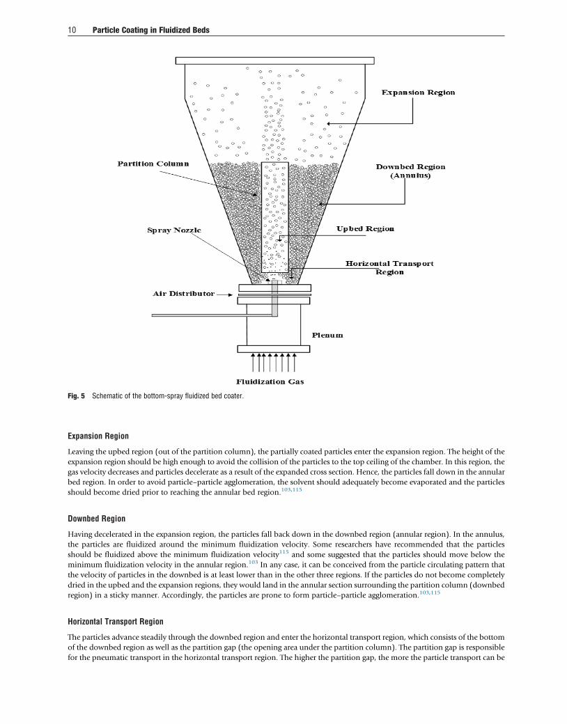
Fig. 5 Schematic of the bottom-spray fluidized bed coater.
10 Particle Coating in Fluidized Beds
Expansion Region
Leaving the upbed region (out of the partition column), the partially coated particles enter the expansion region. The height of the
expansion region should be high enough to avoid the collision of the particles to the top ceiling of the chamber. In this region, the
gas velocity decreases and particles decelerate as a result of the expanded cross section. Hence, the particles fall down in the annular
bed region. In order to avoid particle–particle agglomeration, the solvent should adequately become evaporated and the particles
should become dried prior to reaching the annular bed region.103,115
Downbed Region
Having decelerated in the expansion region, the particles fall back down in the downbed region (annular region). In the annulus,
the particles are fluidized around the minimum fluidization velocity. Some researchers have recommended that the particles
should be fluidized above the minimum fluidization velocity115 and some suggested that the particles should move below the
minimum fluidization velocity in the annular region.103 In any case, it can be conceived from the particle circulating pattern that
the velocity of particles in the downbed is at least lower than in the other three regions. If the particles do not become completely
dried in the upbed and the expansion regions, they would land in the annular section surrounding the partition column (downbed
region) in a sticky manner. Accordingly, the particles are prone to form particle–particle agglomeration.103,115
Horizontal Transport Region
The particles advance steadily through the downbed region and enter the horizontal transport region, which consists of the bottom
of the downbed region as well as the partition gap (the opening area under the partition column). The partition gap is responsible
for the pneumatic transport in the horizontal transport region. The higher the partition gap, the more the particle transport can be

Fig. 6 The coating life cycle in a fluidized bed coater.
Particle Coating in Fluidized Beds 11
achieved. As was discussed above, the air velocity is higher in the central part of the distributor plate (below the partition column)
compared with the air velocity at beneath the downbed region. Consequently, there exists a region of lower pressure below the
partition column, which enables the particles to be conveyed in the horizontal transport region. Afterward, the particles enter the
partition gap into the upbed region and the particles follow the aforementioned circulation pattern once again. This cycle is
repeated several times until the desired coating layer is deposited on the surface of particles.10,11,103,112,114,116
Coating Life cycle in a Spray Fluidized Bed
According to the discussions in the previous section, the particles that move in the fluidized bed chamber experience different
phenomena during their journey in a single coating cycle. A number of physical and transport phenomena occur during the coating
life cycle of the particles which are called117: (1) particle movement, (2) atomization, (3) wetting the particle surfaces, and (4)
drying and film formation. The life cycle of coating in the fluidized bed coaters is discussed in detail in this section. To better
understand the coating life cycle, different phenomena occurring during a coating life cycle are illustrated in Fig. 6.
Particle Movement
The fluidizing gas causes a rising movement of gas and particles in the coater chamber. Different regimes of fluidization can be
observed in fluidized bed coaters, from fixed bed to pneumatic transport. In the top-spray fluidized bed, the particles circulate in
the chamber at the bubbling regime of fluidization. In the tangential-spray fluidized bed, the particles rotate in a spiral motion
caused by fluidization air, rotating disk, and their gravity force. In the Wurster coater, particles experience various moving patterns
in different regions (upbed region, expansion region, downbed region, and horizontal transport region). In the upbed region, the
fluidizing gas propels the particles at the turbulent regime.115 In the expansion region, the particles slow down until falling back
into the downbed region. In the downbed region, the velocity of particles may be either greater or lesser than the minimum
fluidization velocity. In the horizontal transport region, the particles are pneumatically conveyed toward the upbed region. The
movement of particles is discussed in detail in the preceding sections (sections “Top-Spray Fluidized Bed”, “Tangential-Spray
Fluidized Bed”, and “Bottom-Spray Fluidized Bed (Wurster)”).
Atomization
During the coating process, the coating solution is usually sprayed by means of a bifluid nozzle in which the coating solution is
atomized by air under the pressure in the range of 0.5–3.5 bar. Average size of the droplets can be adjusted using the air pressure in
the bifluid nozzle. The higher the atomization pressure, the smaller become the droplet sizes. It is recommended that the droplets
should be smaller than 100 mmand the particle to droplet ratio must be at least 10. On the other hand, small droplets are in favor of
more homogenous final coating.10,90,117 Effect of physical properties of the coating solution on average droplet diameter atomized
by the nozzle can be obtained from5:
dVM,solution
dVM,solvent¼ ssolution
ssolvent
� �0:5� msolution
msolvent
� �0:2� rsolvent
rsolution
� �0:3(3)
where dVM, solution and dVM, solvent are the volume mean droplet diameters of solution and solvent (m), respectively; ssolution,msolution, and rsolution denote the surface tension (N m�1), viscosity (kg m�1 s�1), and density of the solution (kg.m�3), respectively;
ssolvent, msolvent, and rsolvent denote the surface tension (N m�1), viscosity (kg m�1s�1), and density of the solvent (kg m�3),
respectively. The droplet size atomized from the nozzle may be calculated using the following correlation5,90:

12 Particle Coating in Fluidized Beds
dd ¼585�103
ffiffiffiffiffisf3p
vRELffiffiffir
p +597mffiffiffiffiffiffiffiffisfr
p !0:45
1000Usol
Uat
1:5
(4)
where dd is the mean diameter of droplets (mm) and sf, rf, mf, Usol, Uat, and vREL denote the fluid surface tension (N m�1), fluid
density (kg m�3), fluid viscosity (m Pa s�1), fluid volumetric flow rate (m3s�1), air volumetric flow rate (m3s�1), outlet air velocity
(the velocity of air relative to liquid at the atomizer nozzle exit) (m s�1), respectively.
The air pressure influences the droplet temperature. The bed temperature may be calculated as a function of the atomization
pressure and inlet air temperature as follows90:
Tbed ¼�1:07�1:1552Pat + 0:6221Tinlet, P< 0:001, R2 ¼ 0:835 (5)
where Tbed is the bed temperature (�C), Pat denotes the atomization pressure (bar), and Tinlet is the inlet air temperature (�C). Thisequation has been derived for the sodium caseinate coating solution at the atomization pressure of 1.5, 2.5, and 3.5 bar.
The atomization pressure dictates the droplet velocity which also influences the velocity of impact of droplet and particle. In the
Wurster coaters, the particle makes its way from the horizontal transport region through the partition gap into the upbed zone
where the coating material is sprayed via the spray nozzle. The particle velocity in the upbed region varies in the range of 3–5 m/s.
Ejecting from the spray nozzle, the coating droplets have relatively high velocity (approximately 100 m/s). However, the droplets
quickly decelerate, approaching the superficial air velocity. Meanwhile, its solvent evaporates.90,115
Wetting the Particle Surfaces
After injection of the coating solution, there exist a number of micro-level phenomena which should properly take place in order to
have fine coating film around the particle.
Droplet–particle impactRelative velocity of droplets and particles can result in collision. However, not all the collisions lead to adherence. It is illustrated in
Fig. 7 that the droplet–particle collision can be classified into three different mechanisms, including interception, inertia, and
diffusion. According to this classification, the collision by interception is due to the overlap of the droplet and the particle surface
which is the most probable mechanism for larger droplets. If the droplet deviates from its streamline and encounters the surface of
the particle, the inertia mechanism would take place. The inertia mechanism is the favorable mechanism in fluidized bed coating.
If the droplet size is less than 0.001 mm, the droplet–particle collision occurs mainly due to the diffusion mechanism. In this
mechanism, the droplets diffuse across their streamline via the Brownianmotion.115,117 According to Guignon et al.,117 a successful
Fig. 7 Droplet–particle collision: (A) interception, (B) inertia, and (C) diffusion. Adopted from Guignon, B.; Duquenoy, A.; Dumoulin, E. D. Fluid BedEncapsulation of Particles: Principles and Practice. Dry. Technol. 2002, 20, 419–447).

Fig. 8 Droplet contact angle.
Particle Coating in Fluidized Beds 13
coating can be achieved due to interception or inertia in the fluidized bed coaters. Link and Schlunder118 stated that the inertia
mechanism is the most important mechanism for a successful coating in fluidized beds. Therefore, nozzle positioning, spray angle,
number of droplets, and droplet velocity relative to the circulating particles are the most important factors affecting a successful
coating.115
Droplet spreading and adherence on the particle surfaceHaving impinged on the surface of the particles, the droplet should properly spread on the surface of the particle. This microlevel
phenomenon of spreading is of particular importance, especially in thin coating, pesticide application, spray painting, spray
combustion, and spray cooling of hot surfaces.115,117 After the impingement of droplet on the surface of particle, the droplet can sit
as a discrete droplet on the surface of the particle or it can spread out and cover the surface completely (see Fig. 8). The angle which
the liquid–vapor interface meets the solid surface is called the contact angle (y).5
Contact angle can be used to evaluate the wettability of particle by the coating solution. The contact angle may be calculated by
Young’s equation as5:
cosy¼ gSV� gSLgLV
(6)
where gSV is the solid–vapor interfacial tension (N m�1), gSL is the solid–liquid interfacial tension (N m�1), and gLV is the liquid–
vapor interfacial tension (N m�1). Accordingly, in order to improve the spreading of the droplet over the surface of the particle, the
coating formulation must be adjusted in order to wet the particle surface. If the contact angle is less than 90�, wetting of the surfacecan take place and the wetting energy is negative.115,117
Infiltration occurs simultaneously to spreading. This is an unfavorable phenomenon since it decreases the coating yield.
Accordingly, the rate of spreading should be faster than that of infiltration. The infiltration phenomena depend on the property
of the coating material, the interaction between the coating material and the particle, porosity, and pore size distribution.115 Turton
et al.10 reported that decreasing the binder viscosity leads to increasing both droplet spreading rate and infiltration rate.
The adhesion efficiency depends on various parameters, including momentum of droplet and particles at collision, their angle
of incidence, liquid properties, interfacial properties, and the surface structure of particle. Moreover, the drying properties of the
coating material are crucially important since the collision of premature dried droplets may not bring about adhesion of the droplet
to the surface of particle.115 The necessary work of wetting per unit area can be calculated as a function of surface tension of the
solution and contact angle as follows119:
wm ¼�sd�cosy (7)
where sd denotes the droplet surface tension (N m�1). The work of wetting per unit area (J m�2) may also be determined as a
function of liquid–vapor interfacial tension and contact angle as:
wm ¼�gLV � cosy +1ð Þ (8)
It is necessary to note that a negative value for wm is considered as the work of adhesion per unit area (J m�2) which is the
required work to restore initial conditions.5 Sobolev et al.120 concluded that the main mechanisms of droplet–particle adhesion are
as follows:

14 Particle Coating in Fluidized Beds
• Mechanical mechanisms of adhesion, including coating–substrate mechanical interaction and interlocking (keying) as well as
deformation of the substrate surface and rebounding of particles.
• Thermal mechanisms of adhesion, mostly including coating–substrate thermal interactions.
• Diffusive and chemical mechanisms of adhesion.
Drying and Film Formation
Drying of coated particles can be conducted by means of hot fluidizing air during which the solvent is evaporated to advance the
coating deposition on particles. This stage plays an influential role in a successful coating process. A suitable drying condition is in
favor of droplet–particle adherence in the atomization zone. In addition, partially coated particle may satisfactorily be dried in the
air and the possibility of particle agglomeration can be decreased. The drying condition should be suitable for: (1) drying of
partially coated particles and (2) drying of atomized droplets prior to the collision. Therefore, there should be a compromise
between the two above-mentioned concepts.115,117
Becher and Schlunder121 suggested that the heat required for drying of the coated particle (i.e., evaporation of the excess
solvent) may originate from two sources: (a) heat convection with the hot fluidizing gas, (b) heat conduction with the particle.
For a single small and pure droplet (low terminal velocity), the evaporation time (teva) can be determined from the following
equation5,115:
teva ¼lrd d20�d2t� �8k△T
(9)
where l is the latent heat of vaporization, rd denotes the droplet density (kg m�3), d0 and dt are the initial droplet diameter and the
droplet diameter at any time t (m), respectively, k is thermal conductivity of fluidized air (W m�1K�1), and DT is the difference
between the air temperature and droplet surface temperature (K). Werner et al.115 stated that Eq. (9) is not very practical, for the
drying rate is not constant. Therefore, the evaporation time may be calculated in terms of diffusion using Crank’s equation115,122:
Ct �Ce
C0�Ce¼ 6
p2X1n¼1
1
n2exp �n2p2Deff t
R20
(10)
where Ct, Ce, and C0 are the moisture content at any time t, the moisture content at equilibrium e, and the initial moisture content at
0, respectively (kg water/kg dry solid). R is the droplet radius (m) and Deff is the effective moisture diffusivity (m2s�1).
The film formation can be achieved after the solvent is gradually evaporated and the solubility limits are exceeded. All previously
mentioned phenomena interact with the formation of a uniform and coherent film.115,117
Conclusion
Although the coating technology existed for years, it has significantly evolved from 1930. It has been applied in various industries,
especially pharmaceutical, agricultural, and food. The coating solution mainly consists of solvent, polymer, plasticizer, colorant/
opacifier, and antitack agents. Water is the most commonly used solvent. There are many polymers used in coating, as listed in
Table 2. However, the natural polymers are the most preferred ones. Plasticizer, colorant/opacifier, and antitack agent are usually
added to the coating formulation in order to improve the coating properties. In this article, four coating approaches were discussed:
melt coating, supercritical fluid coating, compression coating, and spray drying coating. Spray drying coating (pan coating and air
suspension coating) has offered considerable advantages, which practically enable film coating and multilayer coating of particles.
Air suspension coating is classified into three groups: top-spray fluidized bed, tangential-spray fluidized bed, and bottom-spray
fluidized bed. Top-spray fluidized bed coating is used in food industry because of its simplicity and low cost. Tangential-spray
fluidized bed coating can be used in multilayer coating, although it suffers from some deficiencies. Bottom-spray fluidized bed
coating (Wurster coater) is the most preferred coating equipment due to its excellent characteristics, which provide more
homogenous coating of particles. Finally, the coating mechanism in fluidized bed coaters is discussed in detail. The coating process
is divided into four major stages with different micro scale phenomena including particle movement, atomization, wetting the
particle surfaces (droplet impact, spreading, and adherence), drying, and film formation.
References
1. Gibbs, B. F.; Kermasha, S.; Alli, I.; Mulligan, C. N. Encapsulation in the Food Industry: A Review. Int. J. Food Sci. Nutr. 1999, 50, 213–224.2. Balassa, L. L.; Fanger, G. O.; Wurzburg, O. B. Microencapsulation in the Food Industry. Crit. Rev. Food Sci. Nutr. 1971, 2, 245–265.3. Augustin, M.; Sanguansri, L.; Margetts, C.; Young, B. Microencapsulation of Food Ingredients. Food Austr. 2001, 53, 220–223.4. Tzika, M.; Alexandridou, S.; Kiparissides, C. Evaluation of the Morphological and Release Characteristics of Coated Fertilizer Granules Produced in a Wurster Fluidized Bed.
Powder Technol. 2003, 132, 16–24.5. Cole, G.; Hogan, J. E.; Aulton, M. E. Pharmaceutical Coating Technology; Taylor and Francis: London, 1995.6. Rhodes, C.; Porter, S. Coatings for Controlled-Release Drug Delivery Systems. Drug Dev. Ind. Pharm. 1998, 24, 1139–1154.

Particle Coating in Fluidized Beds 15
7. Dewettinck, K.; Huyghebaert, A. Fluidized Bed Coating in Food Technology. Trends Food Sci. Technol. 1999, 10, 163–168.8. Loffler, F. Staubabscheiden. Lehrreihe Verfahrenstechnik ; Georg-Thieme-Verlag: Stuttgart, 1988.9. Jones, D. M. Factors to Consider in Fluid-Bed Processing. Pharm. Technol. 1985, 9, 50.10. Turton, R.; Tardos, G. I.; Ennis, B. J. Fluidized Bed Coating and Granulation, Selected Topics on Fluidization, Solids Handling and Processing ; Noyes Publications: Westwood,
NJ, 1999; pp 331–429.11. Kleinbach, E.; Riede, T. Coating of Solids. Chem. Eng. Process. Process Intensif. 1995, 34, 329–337.12. Maa, Y.-F.; Nguyen, P.-A.; Hsu, C. C. Spray-Coating of rhDNase on Lactose: Effect of System Design, Operational Parameters and Protein Formulation. Int. J. Pharm. 1996, 144,
47–59.13. Perpar, M.; Lustrik, M.; Srcic, S.; Zun, I. Estimating Coating Quality Parameters on the Basis of Pressure Drop Measurements in a Wurster Draft Tube. Powder Technol. 2013,
246, 41–50.14. Sohi, H.; Sultana, Y.; Khar, R. K. Taste Masking Technologies in Oral Pharmaceuticals: Recent Developments and Approaches. Drug Dev. Ind. Pharm. 2004, 30, 429–448.15. Pearnchob, N.; Siepmann, J.; Bodmeier, R. Pharmaceutical Applications of Shellac: Moisture-Protective and Taste-Masking Coatings and Extended-Release Matrix Tablets. Drug
Dev. Ind. Pharm. 2003, 29, 925–938.16. Vu, K.; Hollingsworth, R.; Leroux, E.; Salmieri, S.; Lacroix, M. Development of Edible Bioactive Coating Based on Modified Chitosan for Increasing the Shelf Life of Strawberries.
Food Res. Int. 2011, 44, 198–203.17. Haq, M. A.; Alam, M. J.; Hasnain, A. Gum Cordia: A Novel Edible Coating to Increase the Shelf Life of Chilgoza (Pinus Gerardiana). LWT – Food Sci. Technol. 2013, 50,
306–311.18. Siepmann, F.; Siepmann, J.; Walther, M.; MacRae, R.; Bodmeier, R. Polymer Blends for Controlled Release Coatings. J. Control. Release 2008, 125, 1–15.19. Savage, G. V.; Rhodes, C. The Sustained Release Coating of Solid Dosage Forms: A Historical Review. Drug Dev. Ind. Pharm. 1995, 21, 93–118.20. Qu, L.; Zhou, Q. T.; Denman, J. A.; Stewart, P. J.; Hapgood, K. P.; Morton, D. A. Influence of Coating Material on the Flowability and Dissolution of Dry-Coated Fine Ibuprofen
Powders. Eur. J. Pharm. Sci. 2015, 78, 264–272.21. Zhou, Q. T.; Qu, L.; Larson, I.; Stewart, P. J.; Morton, D. A. Effect of Mechanical Dry Particle Coating on the Improvement of Powder Flowability for Lactose Monohydrate: A Model
Cohesive Pharmaceutical Powder. Powder Technol. 2011, 207, 414–421.22. Porter, S. The Practical Significance of the Permeability and Mechanical Properties of Polymer Films Used for the Coating of Pharmaceutical Solid Dosage Forms. Int. J. Pharm.
Technol. Prod. Manuf. 1982, 3, 21–25.23. Jono, K.; Ichikawa, H.; Miyamoto, M.; Fukumori, Y. A Review of Particulate Design for Pharmaceutical Powders and Their Production by Spouted Bed Coating. Powder Technol.
2000, 113, 269–277.24. Bansode, S.; Banarjee, S.; Gaikwad, D.; Jadhav, S.; Thorat, R. Microencapsulation: A Review. Int. J. Pharm. Sci. Rev. Res. 2010, 1, 38–43.25. Min, Z.; Yuechao, Y.; Fupeng, S.; Yanxi, S. Study and Industrialized Development of Coated Controlled Release Fertilizers. J. Chem. Fertil. Ind. 2005, 2, 001.26. Kester, J.; Fennema, O. Edible Films and Coatings: A Review. Food Technol. (USA) 1986, 40, 47–59.27. Cuq, B.; Gontard, N.; Guilbert, S. Edible Films and Coatings as Active Layers. In Active Food Packaging; Springer US: Boston, MA, 1995; pp 111–142.28. Cisneros-Zevallos, L.; Saltveit, M. E.; Krochta, J. M. Hygroscopic Coatings Control Surface White Discoloration of Peeled (Minimally Processed) Carrots During Storage. J. Food
Sci. 1997, 62, 363–366.29. Arshady, R. Microcapsules for Food. J. Microencapsul. 1993, 10, 413–435.30. Hogan, J. Coating of Tablets and Multiparticulates, Pharmaceutics: The Science of Dosage Form Design ; Churchill Livingstone: New York, 2001; pp 441–448.31. Dewettinck, K.; Deroo, L.; Messens, W.; Huyghebaert, A. Agglomeration Tendency During Top-Spray Fluidized Bed Coating With Gums. LWT – Food Sci. Technol. 1998, 31,
576–584.32. King, A. H. Encapsulation of Food Ingredients: A Review of Available Technology, Focusing on Hydrocolloids. In Encapsulation and Controlled Release of Food Ingredients; 1990
pp 26–39.33. Wong, T.; Lee, H.; Chan, L.; Heng, P. Drug Release Properties of Pectinate Microspheres Prepared by Emulsification Method. Int. J. Pharm. 2002, 242, 233–237.34. Hun, J. H.; Cennadios, A. Edible Film and Coating: A Review. Innov. Food Packag. 2005, 15, 239–262.35. Tang, E. S.; Chan, L.; Heng, P. W. Coating of Multiparticulates for Sustained Release. Am. J. Drug Deliv. 2005, 3, 17–28.36. Cole, G. C. Coating Pans and Coating Columns, Pharmaceutical Coating Technology ; Taylor and Francis: London, 1995. 205–209.37. Faroongsarng, D.; Peck, G. E. The Swelling of Core Tablets During Aqueous Coating I: A Simple Model Describing Extent of Swelling and Water Penetration for Insoluble Tablets
Containing a Superdisintegrant. Drug Dev. Ind. Pharm. 1991, 17, 2439–2455.38. Faroongsarng, D.; Peck, G. E. The Swelling of Core Tablets During Aqueous Coating II: An Application of the Model Describing Extent of Swelling and Water Penetration for
Insoluble Tablets. Drug Dev. Ind. Pharm. 1992, 18, 1527–1534.39. Thoma, K.; Bechtold, K. Influence of Aqueous Coatings on the Stability of Enteric Coated Pellets and Tablets. Eur. J. Pharm. Biopharm. 1999, 47, 39–50.40. O’Donnell, P. B.; Wu, C.; Wang, J.; Wang, L.; Oshlack, B.; Chasin, M.; Bodmeier, R.; McGinity, J. W. Aqueous Pseudolatex of Zein for Film Coating of Solid Dosage Forms. Eur.
J. Pharm. Biopharm. 1997, 43, 83–89.41. Abletshauser, C.; Schneider, R.; Rupprecht, H. Film Coating of Pellets With Insoluble Polymers Obtained In Situ Crosslinking in the Fluidized Bed. J. Control. Release 1993, 27,
149–156.42. Kim, T. H.; Park, Y. H.; Kim, K. J.; Cho, C. S. Release of Albumin From Chitosan-Coated Pectin Beads in Vitro. Int. J. Pharm. 2003, 250, 371–383.43. Pillay, V.; Fassihi, R. In Vitro Release Modulation From Crosslinked Pellets for Site-Specific Drug Delivery to the Gastrointestinal Tract: I. Comparison of pH-Responsive Drug
Release and Associated Kinetics. J. Control. Release 1999, 59, 229–242.44. Chang, R.-K.; Iturrioz, G.; Luo, C.-W. Preparation and Evaluation of Shellac Pseudolatex as an Aqueous Enteric Coating System for Pellets. Int. J. Pharm. 1990, 60, 171–173.45. Fulzele, S.; Satturwar, P.; Dorle, A. Polymerized Rosin: Novel Film Forming Polymer for Drug Delivery. Int. J. Pharm. 2002, 249, 175–184.46. Porter, S. C. Controlled-Release Film Coatings Based on Ethylcellulose. Drug Dev. Ind. Pharm. 1989, 15, 1495–1521.47. Wan, L. S.; Lai, W. Factors Affecting Drug Release From Drug-Coated Granules Prepared by Fluidized-Bed Coating. Int. J. Pharm. 1991, 72, 163–174.48. Husson, I.; Leclerc, B.; Spenlehauer, G.; Veillard, M.; Puisieux, F.; Couarraze, G. Influence of Size Polydispersity on Drug Release From Coated Pellets. Int. J. Pharm. 1992, 86,
113–121.49. Leszek, K. Excipients Used in the Formulation of Extended-Release Dosage Forms, Extended Release Dosage Forms; CRC Press: Florida, 1987; pp 171–188.50. Hogan, J. E. Film-Coating Materials and Their Properties. Pharm. Coat. Technol. 1995, 27–33.51. Gutierrez-Rocca, J.; McGinity, J. W. Influence of Water Soluble and Insoluble Plasticizers on the Physical and Mechanical Properties of Acrylic Resin Copolymers. Int. J. Pharm.
1994, 103, 293–301.52. Immergut, E. H.; Mark, H. F. In Plasticization and Plasticizer Processes; Platzer, N. A., Ed.; American Chemical Society: Washington, DC, 1965; vol. 48, pp 1–26.53. Rowe, R. Modulus Enhancement in Pigmented Tablet Film Coating Formulations. Int. J. Pharm. 1983, 14, 355–359.54. Lindberg, N.; Jonsson, E. Film-Coating by Hydroxypropyl Cellulose in an Automatic Process. II. Evaluation of Coating Solutions. Acta Pharmaceutica Suecica 1972, 9, 589.55. Chan, L.; Chan, W.; Heng, P. An Improved Method for the Measurement of Colour Uniformity in Pellet Coating. Int. J. Pharm. 2001, 213, 63–74.56. Vemuri, S. Color Stability of Ascorbic Acid Tablets Measured by Tristimulus Colorimeter. Drug Dev. Ind. Pharm. 1985, 11, 207–222.57. Wirth, M. Instrumental Color Measurement: A Method for Judging the Appearance of Tablets. J. Pharm. Sci. 1991, 80, 1177–1179.58. Wan, L. S.; Lai, W. The Influence of Antitack Additives on Drug Release From Film-Coated Granules. Int. J. Pharm. 1993, 94, 39–47.

16 Particle Coating in Fluidized Beds
59. Wesseling, M.; Kuppler, F.; Bodmeier, R. Tackiness of Acrylic and Cellulosic Polymer Films Used in the Coating of Solid Dosage Forms. Eur. J. Pharm. Biopharm. 1999, 47,73–78.
60. Kucera, S. A. Physical and Chemical Properties of Acrylic Polymers Influencing Physical Aging; The University of Texas at Austin: ProQuest, 2007.61. Jozwiakowski, M. J.; Jones, D. M.; Franz, R. M. Characterization of a Hot-Melt Fluid Bed Coating Process for Fine Granules. Pharm. Res. 1990, 7, 1119–1126.62. Kennedy, J. P.; Niebergall, P. J. Development and Optimization of a Solid Dispersion Hot-Melt Fluid Bed Coating Method. Pharm. Dev. Technol. 1996, 1, 51–62.63. Achanta, A. S.; Adusumilli, P. S.; James, K. W.; Rhodes, C. T. Development of Hot Melt Coating Methods. Drug Dev. Ind. Pharm. 1997, 23, 441–449.64. Jones, D.; Percel, P. Coating of Multiparticulates Using Molten Materials. Formulation and Process Considerations. Drugs Pharm. Sci. 1994, 65, 113–142.65. Joachim, J.; Cauture, E. A Hot-Melt Coating Agent for Controlled Release. Pharm. Manuf. Rev. 1996, 8, 24–27.66. Jung, J.; Perrut, M. Particle Design Using Supercritical Fluids: Literature and Patent Survey. J. Supercrit. Fluids 2001, 20, 179–219.67. Thies, C.; Dos Santos, I. R.; Richard, J.; VandeVelde, V.; Rolland, H.; Benoit, J.-P. A Supercritical Fluid-Based Coating Technology 1: Process Considerations. J. Microencapsul.
2003, 20, 87–96.68. Bose, S.; Bogner, R. H. Solventless Pharmaceutical Coating Processes: A Review. Pharm. Dev. Technol. 2007, 12, 115–131.69. Tom, J. W.; Debenedetti, P. G. Particle Formation With Supercritical Fluids—A Review. J. Aerosol Sci. 1991, 22, 555–584.70. Ozeki, Y.; Ando, M.; Watanabe, Y.; Danjo, K. Evaluation of Novel one-Step Dry-Coated Tablets as a Platform for Delayed-Release Tablets. J. Control. Release 2004, 95, 51–60.71. Matsuo, M.; Nakamura, C.; Arimori, K.; Nakano, M. Evaluation of Hydroxyethyl Cellulose as a Hydrophilic Swellable Material for Delayed-Release Tablets. Chem. Pharm. Bull.
1995, 43, 311–314.72. Takeuchi, H.; Yasuji, T.; Yamamoto, H.; Kawashima, Y. Spray-Dried Lactose Composite Particles Containing an ion Complex of Alginate-Chitosan for Designing a Dry-Coated
Tablet Having a Time-Controlled Releasing Function. Pharm. Res. 2000, 17, 94–99.73. Peerapattana, J.; Otsuka, K.; Otsuka, M. Time-Controlled Pulse-Drug Release From Dry-Coated Wax Matrix Tablets for Colon Drug Delivery. Biomed. Mater. Eng. 2004, 14,
293–301.74. Takeuchi, H.; Yasuji, T.; Hino, T.; Yamamoto, H.; Kawashima, Y. Spray-Dried Composite Particles of Lactose and Sodium Alginate for Direct Tabletting and Controlled Releasing.
Int. J. Pharm. 1998, 174, 91–100.75. Pearnchob, N.; Bodmeier, R. Dry Polymer Powder Coating and Comparison With Conventional Liquid-Based Coatings for Eudragit® RS, Ethylcellulose and Shellac. Eur.
J. Pharm. Biopharm. 2003, 56, 363–369.76. Pearnchob, N.; Bodmeier, R. Coating of Pellets With Micronized Ethylcellulose Particles by a Dry Powder Coating Technique. Int. J. Pharm. 2003, 268, 1–11.77. Zheng, W.; Cerea, M.; Sauer, D.; McGinity, J. Properties of Theophylline Tablets Powder-Coated With Methacrylate Ester Copolymers. J. Drug Deliv. Sci. Technol. 2004, 14,
319–325.78. Ichikawa, H.; Fujioka, K.; Adeyeye, M. C.; Fukumori, Y. Use of Ion-Exchange Resins to Prepare 100 mm-Sized Microcapsules With Prolonged Drug-Release by the Wurster
Process. Int. J. Pharm. 2001, 216, 67–76.79. Sun, Y.-M.; Chang, C.-C.; Huang, W.-F.; Liang, H.-C. Fluidized-Bed Spray Coated Porous Hydrogel Beads for Sustained Release of Diclofenac Sodium. J. Control. Release
1997, 47, 247–260.80. Williams, R. O., III; Liu, J. Influence of Processing and Curing Conditions on Beads Coated With an Aqueous Dispersion of Cellulose Acetate Phthalate. Eur. J. Pharm. Biopharm.
2000, 49, 243–252.81. Berggren, J.; Frenning, G.; Alderborn, G. Compression Behaviour and Tablet-Forming Ability of Spray-Dried Amorphous Composite Particles. Eur. J. Pharm. Sci. 2004, 22,
191–200.82. Jones, D. Air Suspension Coating for Multiparticulates. Drug Dev. Ind. Pharm. 1994, 20, 3175–3206.83. Deasy, P. B. Microencapsulation and Related Drug Processes; Marcel Dekker Incorporated: New York, 1984.84. Srivastava, S.; Mishra, G. Fluid Bed Technology: Overview and Parameters for Process Selection. Int. J. Pharm. Sci. Drug Res. 2010, 2, 236–246.85. Filkova, I.; Mujumdar, A. S. Industrial Spray Drying Systems. In Handbook of Industrial Drying; Marcel Dekkar Inc: New York, 1995, pp 263–308.86. Jones, D. M. Controlling Particle Size and Release Properties: Secondary Processing Techniques. In ACS Symposium Series-American Chemical Society (USA); 1988.87. Palamanit, A.; Prachayawarakorn, S.; Tungtrakul, P.; Soponronnarit, S. Performance Evaluation of Top-Spray Fluidized Bed Coating for Healthy Coated Rice Production. Food
Bioprocess Technol. 2016, 1–10.88. Abrahamsen, A. R.; Geldart, D. Behaviour of Gas-Fluidized Beds of Fine Powders Part I. Homogeneous Expansion. Powder Technol. 1980, 26, 35–46.89. Tan, K.-K.; Tan, Y.-W.; Tey, B.-T.; Look, K.-Y. On the Onset of Incipient Fluidization. Powder Technol. 2008, 187, 175–180.90. Dewettinck, K.; Huyghebaert, A. Top-Spray Fluidized Bed Coating: Effect of Process Variables on Coating Efficiency. LWT – Food Sci. Technol. 1998, 31, 568–575.91. Kandukuri, J. M.; Allenki, V.; Eaga, C. M.; Keshetty, V.; Jannu, K. K. Pelletization Techniques for Oral Drug Delivery. Int. J. Pharm. Sci. Drug Res. 2009, 1, 63–70.92. Eichler, K. Fluid Bed Film Coating. In vol. 12; Proceedings of the TTC Workshop n�53 on “Nutraceutical and Probiotics”, Binzen (Germany), 26–28 June; 2002; pp 1–9.93. Othomer, D. Background, History and Future of Fluid Bed Systems Fluidization; Reinhold Publishing Corporation: New York, 1956.94. Watano, S.; Sato, Y.; Miyanami, K.; Murakami, T.; Ito, Y.; Kamata, T.; Oda, N. Scale-Up of Agitation Fluidized Bed Granulation. I. Preliminary Experimental Approach for
Optimization of Process Variables. Chem. Pharm. Bull. 1995, 43, 1212–1216.95. Prusse, U. Practical Aspects of Encapsulation Technologies. In Workshop Practical Aspects of Encapsulation Technologies (2001: FAL), Bundesforschungsanstalt fur
Landwirtschaft (FAL), 2002.96. Vecchio, C.; Fabiani, F.; Sangalli, M.; Zema, L.; Gazzaniga, A. Rotary Tangential Spray Technique for Aqueous Film Coating of Indobufen Pellets. Drug Dev. Ind. Pharm. 1998,
24, 269–274.97. Kristensen, J.; Schæfer, T.; Kleinebudde, P. Direct Pelletization in a Rotary Processor Controlled by Torque Measurements. I. Influence of Process Variables. Pharm. Dev.
Technol. 2000, 5, 247–256.98. Sandeep, D.; Battu, S. An Overview on Multiparticulate Drug Delivery System: Pellets. Int. J. Pharm. Anal. Res. 2015, 4, 264–275.99. Ghebre-Selassie, I. Pharmaceutical Pelletization Technology ; Marcel Dekker: New York, 1989.100. Means for Applying Coatings to Tablets or the Like, in, Google Patents, 1957.101. D.E. Wurster, J.A. Lindlof, Particle Coating Apparatus, in, Google Patents, 1966.102. KuShaari, K.; Pandey, P.; Song, Y.; Turton, R. Monte Carlo Simulations to Determine Coating Uniformity in a Wurster Fluidized Bed Coating Process. Powder Technol. 2006,
166, 81–90.103. Christensen, F. N.; Bertelsen, P. Qualitative Description of the Wurster-Based Fluid-Bed Coating Process. Drug Dev. Ind. Pharm. 1997, 23, 451–463.104. Cheng, X.; Turton, R. The Prediction of Variability Occurring in Fluidized Bed Coating Equipment. II. The Role of Nonuniform Particle Coverage as Particles Pass Through the
Spray Zonemr. Pharm. Dev. Technol. 2000, 5, 323–332.105. Shelukar, S.; Ho, J.; Zega, J.; Roland, E.; Yeh, N.; Quiram, D.; Nole, A.; Katdare, A.; Reynolds, S. Identification and Characterization of Factors Controlling Tablet Coating
Uniformity in a Wurster Coating Process. Powder Technol. 2000, 110, 29–36.106. Mehta, A. M.; Jones, D. M. Coated Pellets Under the Microscope. Pharm. Technol. 1985, 9, 52–60.107. Wesdyk, R.; Joshi, Y.; De Vincentis, J.; Newman, A.; Jain, N. Factors Affecting Differences in Film Thickness of Beads Coated in Fluidized Bed Units. Int. J. Pharm. 1993, 93,
101–109.108. Olsen, K. Batch Fluid-Bed Processing Equipment a Design Overview Part I. Pharm. Technol. 1989, 13, 34–46.109. Karlsson, S.; Bjorn, I. N.; Folestad, S.; Rasmuson, A. Measurement of the Particle Movement in the Fountain Region of a Wurster Type Bed. Powder Technol. 2006, 165, 22–29.110. Teunou, E.; Poncelet, D. Batch and Continuous Fluid Bed Coating—Review and State of the Art. J. Food Eng. 2002, 53, 325–340.

Particle Coating in Fluidized Beds 17
111. Bertelsen, P.; Christensen, F. N.; Holm, P.; Jørgensen, K. Comparison of Organic Solvent-Based Ethylcellulose Coatings of KCl Crystals Applied by Top and Bottom Spraying inFluidized-Bed Equipment. Int. J. Pharm. 1994, 111, 117–125.
112. Geldart, D.; Rhodes, M. From Minimum Fluidization to Pneumatic Transport—A Critical Review of the Hydrodynamics ; Circulating Fluidized Bed Technology; Pergamon Press:Oxford, 1986. pp 21–31.
113. Bader, R.; Findlay, J.; Knowlton, T. Gas/Solid Flow Patterns in a 30.5 cm Diameter Circulating Fluidized Bed. Circulating Fluidized Bed Technology II; 123–137.114. Porter, S. C.; Bruno, C. H. Coating of Pharmaceutical Dosage Forms. In Pharmaceutical Dosage Forms Tablets; Lieberman, H. A. Lachman, L.; Schwartz, J. B., Eds.; Dekker:
New York, 1990; pp 77–159.115. Werner, S. R.; Jones, J. R.; Paterson, A. H.; Archer, R. H.; Pearce, D. L. Air-Suspension Coating in the Food Industry: Part II—Micro-Level Process Approach. Powder Technol.
2007, 171, 34–45.116. Rhodes, M.; Geldart, D. A Model for the Circulating Fluidized Bed. Powder Technol. 1987, 53, 155–162.117. Guignon, B.; Duquenoy, A.; Dumoulin, E. D. Fluid Bed Encapsulation of Particles: Principles and Practice. Dry. Technol. 2002, 20, 419–447.118. Link, K. C.; Schlunder, E.-U. Fluidized Bed Spray Granulation: Investigation of the Coating Process on a Single Sphere. Chem. Eng. Process. Process Intensif. 1997, 36,
443–457.119. Briant, J. Phenomenes d’interface. Agents de surface: principes et modes d’action; Editions Technip: Paris, 1989.120. Sobolev, V.; Guilemany, J.; Nutting, J.; Miquel, J. Development of Substrate-Coating Adhesion in Thermal Spraying. Int. Mater. Rev. 1997, 42, 117–136.121. Becher, R.-D.; Schlunder, E.-U. Fluidized Bed Granulation—The Importance of a Drying Zone for the Particle Growth Mechanism. Chem. Eng. Process. Process Intensif. 1998,
37, 1–6.122. Foroughi-Dahr, M.; Golmohammadi, M.; Pourjamshidian, R.; Rajabi-Hamaneh, M.; Hashemi, S. On the Characteristics of Thin-Layer Drying Models for Intermittent Drying of
Rough Rice. Chem. Eng. Commun. 2015, 202, 1024–1035.