particulate filtration in nuclea facilitier s
TRANSCRIPT

TECHNICAL REPORTS SERIES No 325
Particulate Filtration in Nuclear Facilities
t W INTERNATIONAL ATOMIC ENERGY AGENCY, VIENNA, 1991

Particulate filtration in nuclear AN: 122654 c .3 U N : 66 .067 P273
D 0 0 D 1 1 B 5 3 7 3

PARTICULATE FILTRATION IN NUCLEAR FACILITIES

The fol lowing States are Members of the International Atomic Energy Agency:
AFGHANISTAN HOLY SEE PERU ALBANIA HUNGARY PHILIPPINES ALGERIA ICELAND POLAND ARGENTINA INDIA PORTUGAL AUSTRALIA INDONESIA QATAR AUSTRIA IRAN, ISLAMIC REPUBLIC OF ROMANIA BANGLADESH IRAQ SAUDI ARABIA BELGIUM IRELAND SENEGAL BOLIVIA ISRAEL SIERRA LEONE BRAZIL ITALY SINGAPORE BULGARIA JAMAICA SOUTH AFRICA BYELORUSSIAN SOVIET JAPAN SPAIN
SOCIALIST REPUBLIC JORDAN SRI LANKA CAMEROON KENYA SUDAN CANADA KOREA, REPUBLIC OF SWEDEN CHILE KUWAIT SWITZERLAND CHINA LEBANON SYRIAN ARAB REPUBLIC COLOMBIA LIBERIA THAILAND COSTA RICA LIBYAN ARAB JAMAHIRIYA TUNISIA COTE D'lVOIRE LIECHTENSTEIN TURKEY CUBA LUXEMBOURG UGANDA CYPRUS MADAGASCAR UKRAINIAN SOVIET SOCIALIST CZECHOSLOVAKIA MALAYSIA REPUBLIC DEMOCRATIC KAMPUCHEA MALI UNION OF SOVIET SOCIALIST DEMOCRATIC PEOPLE'S MAURITIUS REPUBLICS
REPUBLIC OF KOREA MEXICO UNITED ARAB EMIRATES DENMARK MONACO UNITED KINGDOM OF GREAT DOMINICAN REPUBLIC MONGOLIA BRITAIN AND NORTHERN ECUADOR MOROCCO IRELAND EGYPT MYANMAR UNITED REPUBLIC OF EL SALVADOR NAMIBIA TANZANIA ETHIOPIA NETHERLANDS UNITED STATES OF AMERICA FINLAND NEW ZEALAND URUGUAY FRANCE NICARAGUA VENEZUELA GABON NIGER VIET NAM GERMANY NIGERIA YUGOSLAVIA GHANA NORWAY ZAIRE GREECE PAKISTAN ZAMBIA GUATEMALA PANAMA ZIMBABWE HAITI PARAGUAY
The A g e n c y ' s Statute was approved on 23 October 1956 by the Conference on the Statute of the I A E A held at United Nat ions Headquar ters , New York ; it entered into force on 2 9 July 1957. The Head-quarters of the Agency are situated in Vienna. Its principal objective is " t o accelerate and enlarge the contribution of a tomic energy to peace, health and prosperi ty throughout the w o r l d ' ' .
© IAEA, 1991
Permiss ion to reproduce or translate the information contained in this publication may be obtained by writ ing to the International Atomic Energy Agency , Wagramers t rasse 5, P . O . Box 100, A-1400 Vienna, Austr ia .
Printed by the IAEA in Austria August 1991
TECHNICAL REPORTS SERIES No. 325
PARTICULATE FILTRATION IN NUCLEAR FACILITIES
INTERNATIONAL ATOMIC ENERGY AGENCY VIENNA, 1991

PARTICULATE FILTRATION IN NUCLEAR FACILITIES IAEA, VIENNA, 1991
STI/DOC/10/325 ISBN 92-0-125491-1
ISSN 0074-1914

FOREWORD
The removal of particulate radioactive material from exhaust air or gases is an essential feature of virtually all nuclear facilities. Recent IAEA publications have covered the broad designs of off-gas and air cleaning systems for the range of nuclear power plants and other facilities. This report is a complementary guidebook that examines in detail the latest developments in the design, operation, maintenance and testing of fibrous air filters.
The original draft of the report was prepared by three consultants, M.W. First, of the School of Public Health, Harvard University, United States of America, K.S. Robinson, from the UKAEA Harwell Laboratory, United Kingdom, and H. G. Dillmann, of the Kernforschungszentrum, Karlsruhe, Germany. The Technical Committee Meeting (TCM), at which the report was reviewed and much additional information contributed, was attended by 11 experts and was held in Vienna, from 30 May to 3 June 1988.
The IAEA wishes to express its gratitude to those who have taken part in the preparation of this report, particularly the consultants and the chairman of the meet-ing, W. Bergman (USA). The Scientific Secretary for the TCM was V. Friedrich and the officer responsible for the final report was G. R. Plumb, both from the Waste Management Section of the IAEA Division of Nuclear Fuel Cycle and Waste Management.

EDITORIAL NOTE
This text was compiled before the unification of Germany in October 1990. Therefore the names German Democratic Republic and Federal Republic of Germany have been retained.
CONTENTS
1. i n t r o d u c t i o n . . . ' i
2. FUNDAMENTALS OF FILTRATION 3
2.1. Filter flow resistance 3
2.2. Basic filtration mechanisms 6 2.2.1. Diffusional capture mechanism 8 2.2.2. Inertia-interception collision mechanism 11 2.2.3. Electrical collision mechanism 12
2.3. Filter efficiency 13
2.4. Filter loading 17
3. CHARACTERISTICS OF FILTRATION SYSTEMS 20
3.1. HEPA filters 20 3.1.1. Design of filter units 22
3.1.1.1. Filter medium 23 3.1.1.2. Frame (filter casing) 26 3.1.1.3. Spacers or separators 26 3.1.1.4. Adhesive or cement 26 3.1.1.5. Gaskets 27
3.1.2. Properties of filter units 27 3.1.2.1. Air flow capacity and geometrical size 27 3.1.2.2. Pressure drop 27 3.1.2.3. Penetration 28 3.1.2.4. Dust holding capacity 32 3.1.2.5. Resistance to overpressure, heat, fire,
humidity and chemical attack 33 3.1.2.6. Mechanical resistance 38 3.1.2.7. Ageing of filter inserts 38

3.2. Protection of HEPA filters 39 3.2.1. Prefilters 39 3.2.2. Demisters 40 3.2.3. Other devices 40 3.2.4. System design 40
4. USE OF AEROSOL FILTERS IN NUCLEAR FACILITIES 41
4.1. Inlet air filters 41
4.2. Effluent air filtration for normal environmental conditions 41 4.2.1. Laboratory space ventilation 41 4.2.2. Glove boxes 42 4.2.3. Nuclear power plants 42
4.3. Effluent air filtration process plants and accident conditions 43 4.3.1. Process plant effluent filtration 43 4.3.2. Emergency stand-by filters 43
4.3.2.1. Filters for design base accidents 44 4.3.2.2. Emergency stand-by filters for
hypothetical accidents 44
5. VENTILATION AND FILTER SYSTEMS 47
5.1. General design principles 47 5.1.1. Inlet air filtration 47 5.1.2. Once-through flow 50 5.1.3. The zone principle 50 5.1.4. Flow distribution 53 5.1.5. Efficient use of ventilation air 56 5.1.6. Exhaust air centralized systems 56 5.1.7. Accident conditions 57 5.1.8. Final filtration 58
5.2. Laboratories, cells and reactor buildings 58 5.2.1. Laboratories 58
5.2.1.1. Fume cupboards 60 5.2.1.2. Open boxes 60 5.2.1.3. Glove boxes 60 5.2.1.4. Single pass ventilation systems 61 5.2.1.5. Recirculating systems 64
5.2.2. ceils- 64 5.2.3. Reactor buildings : 65
5.3. Filter housings ; :....... .'. .: . .: . . . . . 66 5.3.1. Unshielded housings 66
5.3.1.1: Canister housings 66 5.3.1.2. Shelf system 67 5.3.1.3. Ladder system /.....'. 69 5.3.1.4. Glove box system . . . . . . . . . ; . . . . . . . . . 69
5.3.2. Shielded installations 69 5.3.2.1. Low flow rate applications 72 5.3.2.2. High flow rate applications 72
5.4. Commissioning - •••• 73
6. HANDLING, INSPECTION AND INSTALLATION OF
NEW FILTER INSERTS 74
6.1. Acceptance of filter insert shipment and quality assurance 74
6.2. Filter insert storage 74 6.2.1. Withdrawing filters from storage for use 75
6.3. Pre-installation unpacking and inspection 75 6.3.1. Filter unpacking 75 6.3.2. Inspection prior to installation 76
6.4. Installation 76
6.5. Health physics and ergonomic considerations 77 6.5.1. Size of filter banks 77 6.5.2. Layout of filter banks ' 77
7. FILTER TESTING 80
7.1. Filter test goals 80
7.2. Test methods for filter efficiency 80 7.2.1. Fundamentals 80 7.2.2. Description of test methods used in various countries 84
7.3. Test methods for other filter characteristics 89
8. HANDLING, STORAGE AND DISPOSAL OF CONTAMINATED FILTER INSERTS 89
8.1. Removal and bagging of contaminated filter inserts 89
8.2. Classification and storage of contaminated filter inserts 89
8.3. Disposal of contaminated filter inserts 91 8.3.1. Low level contaminated inserts 91 8.3.2. Intermediate level contaminated inserts 91
9. TRENDS AND DEVELOPMENTS 92
9.1. Filter design 93 9.1.1. Improved filter media 93 9.1.2. Filter geometry. 93 9.1.3. Electric filters 93 9.1.4. Cleanable HEPA filters 94 9.1.5. Cleanable sintered metal filters 94
9.2. Filter testing 94 9.2.1. Retention efficiency 94 9.2.2. In situ tests 95 9.2.3. Other test methods 95
9.3. Filter insert disposal 95
REFERENCES 97
CONTRIBUTORS TO DRAFTING AND REVIEW 101

1. INTRODUCTION
The purpose of this publication is to collect the relevant information on air filtration for all types of facilities that handle or generate aerosols containing radio-active particles. Specifically, this report is intended to provide information on the design, testing, operation and maintenance of air filter installations at nuclear facili-ties of all kinds.
The air cleaning systems of all nuclear facilities have a vital role in ensuring that air in working areas and in the environment outside the facility remains free from radioactive contamination. The International Commission on Radiological Pro-tection (ICRP) emphasizes the need to keep the man-made radiation exposure of the general public and of occupationally exposed workers "as low as reasonably achiev-able", taking "social and economic factors" into account (often referred to as the ALARA principle), and to keep the dose to any individual below specified limits [1],
This report is concerned with the removal of airborne particles by filtration. The main goal of the filtration units installed in the ventilation systems of nuclear facilities is to maintain radioactive aerosols at all times within the limits of the build-ings. For this reason, designs have to be adequate for normal operation and must be able to cope with any incident or accident conditions.
Current practices in nuclear industries are based on high efficiency particulate air (HEPA) filtration as the preferred method for treating radioactive aerosols. There are occasional exceptions, for example in the decontamination of high temperature off-gases from incineration processes where HEPA filtration is likely to be used only as a final air cleaning stage after the gases have been cooled and the particulate con-centration reduced to a low value by other methods. The great importance of aerosol filtration for the safe operation of all nuclear industries justifies the simplification of publisned information on this air cleaning method and the updating of information contained in previous IAEA publications.
For this reason, this report will be concerned mainly with fibrous HEPA filters, the design modifications to withstand more severe operating conditions and the means developed to increase resistance to heat, fire, condensation and dust load-ing. There are various systems capable of performing a primary removal of the radioactive aerosols produced within the process which are available or under development. Some were described in earlier IAEA publications [2-4], There are other IAEA publications that contain important information on the design, construc-tion and application of aerosol filters [5-7]. Because the subject of this report is air filtration, the other essential components of a filtration system (e.g. ducts, fans and instruments) will not be covered. However, filter housings will be covered in con-siderable detail, inasmuch as they have an important influence on the correct func-tioning of high efficiency filter systems.
1

The emphasis in this report is on HEP A filters, because of their great ability to reduce particulate emissions and their wide degree of usage in nuclear installa-tions, though other types of filters useful in nuclear applications are also given exten-sive coverage. In addition to describing these filter types, their dimensions and the materials used in their construction, this report covers the different forms of their use. It also provides information on filter testing and handling practices to ensure effective and safe performance. It should serve as an introduction on the use of all types of particulate air filters in countries where work with radioactive materials has only recently commenced. The list of references at the end of the book indicates sources of more advanced information for those with comprehensive experience in this field.
Although it is assumed that filters will be obtained from a manufacturer, this report contains information on the design and construction of the filter unit to help the user understand the special properties and limitations of the various filters and to use this knowledge in the selection of optimum filter types for specific applica-tions. Additional assistance in providing an understanding of the fundamental princi-ples in air filtration is provided in the form of a section on aerosol characterization and filtration mechanisms. This report also deals with the cleaning of intake air to a plant. Special consideration is given to the recovery, packaging, transportation and ultimate disposal of spent air filters, in recognition of the increasing importance of safe and environmentally acceptable nuclear waste handling techniques.
Work involving the handling of radioactive material may cause the surround-ing air to become contaminated. During the fabrication of fuel elements for nuclear reactors, uranium dust is formed, or, in a reactor plant, fission products and the activity induced in the cooling medium may appear outside the closed system and contaminate the air. In a reprocessing plant, large quantities of fission products are handled and in isotope production plants many types of nuclides are processed. Medical and scientific laboratories use radioactive isotopes as an aid in many tests and investigations and, although the quantities are usually small, special vigilance is needed to avoid the release of contamination into the air. The personnel inside such plants can be protected by well designed ventilation systems and by using engineered protective devices, such as fume hoods and glove boxes. Outside the building, an unacceptable level of radioactive contamination from air released into the atmosphere is avoided by the use of air filtration prior to discharge into the environment.
The extent of removal necessary may have to be determined on the basis of a maximum credible release under accident conditions, as well as on a normal operat-ing level of contamination. Sometimes, technical reasons, such as the necessity for low background contamination in the plant, will dictate the level of efficiency needed for a filter installation, e.g. to protect material such as photographic film sensitive to radiation, or to provide an uncontaminated atmosphere in an analytical laboratory measuring low levels of radiation. Before the design of a ventilation and air cleaning
2
plant is considered, all means of minimizing the formation of aerosols in the build-ing, such as wet handling and reduction of the amount of radioactive material involved in the processes, should have been studied. If the formation of dusts cannot be avoided, the hazards from aerosols can be reduced by enclosing the process in hoods, fume cupboards, glove boxes and hot cells. The smaller volume of air involved with the use of such confinement structures reduces the size of the filter installation in the same proportion, even if a higher dust concentration leads to more frequent changing of the filters.
2. FUNDAMENTALS OF FILTRATION
The initial approach to understanding particle collection efficiency and airflow resistance for. a macroscopic air filter is to recognize the two characteristics of the microscopic elements that make up the filter. The most common air filters consist of a matrix of fibres or granules, although other geometries are also sometimes found. Once the microscopic behaviour is understood, the particle collection effi-ciency and the airflow resistance of the macroscopic filter elements are integrated to yield the corresponding values for the media and assembled filter. The following treatment is based largely on reviews [8-11].
2.1. FILTER FLOW RESISTANCE
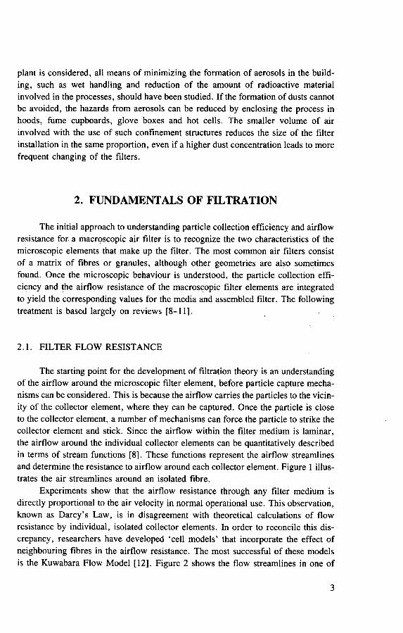
The starting point for the development of filtration theory is an understanding of the airflow around the microscopic filter element, before particle capture mecha-nisms can be considered. This is because the airflow carries the particles to the vicin-ity of the collector element, where they can be captured. Once the particle is close to the collector element, a number of mechanisms can force the particle to strike the collector element and stick. Since the airflow within the filter medium is laminar, the airflow around the individual collector elements can be quantitatively described in terms of stream functions [8]. These functions represent the airflow streamlines and determine the resistance to airflow around each collector element. Figure 1 illus-trates the air streamlines around an isolated fibre.
Experiments show that the airflow resistance through any filter medium is directly proportional to the air velocity in normal operational use. This observation, known as Darcy's Law, is in disagreement with theoretical calculations of flow resistance by individual, isolated collector elements. In order to reconcile this dis-crepancy, researchers have developed 'cell models' that incorporate the effect of neighbouring fibres in the airflow resistance. The most successful of these models is the Kuwabara Flow Model [12], Figure 2 shows the flow streamlines in one of
3
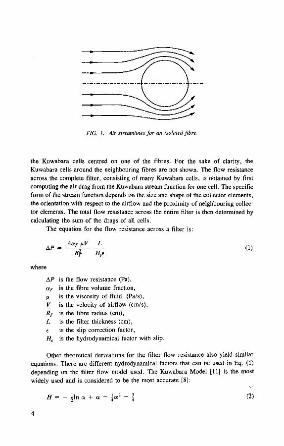
FIG. 1. Air streamlines for an isolated fibre.
the Kuwabara cells centred on one of the fibres. For the sake of clarity, the Kuwabara cells around the neighbouring fibres are not shown. The flow resistance across the complete filter, consisting of many Kuwabara cells, is obtained by first computing the air drag from the Kuwabara stream function for one cell. The specific form of the stream function depends on the size and shape of the collector elements, the orientation with respect to the airflow and the proximity of neighbouring collec-tor elements. The total flow resistance across the entire filter is then determined by calculating the sum of the drags of all cells.
The equation for the flow resistance across a filter is:
AP = AaF fj.V L
Rl H,e (1)
where
A P is the aF is the M is the V is the Rf is the L is the e is the Hs is the
Other theoretical derivations for the filter flow resistance also yield similar equations. There are different hydrodynamical factors that can be used in Eq. (1) depending on the filter flow model used. The Kuwabara Model [11] is the most widely used and is considered to be the most accurate [8]:
H = - jln a + a - y (2)
4
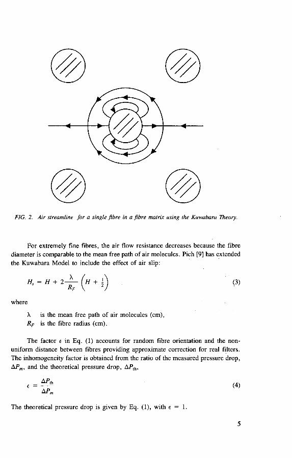
FIG. 2. Air streamline for a single fibre in a fibre matrix using the Kuwabara Theory.
|For extremely fine fibres, the air flow resistance decreases because the fibre diameter is comparable to the mean free path of air molecules. Pich [9] has extended the Kuwabara Model to include the effect of air slip:
X is the mean free path of air molecules (cm), RF is the fibre radius (cm).
The factor e in Eq. (1) accounts for random fibre orientation and the non-uniform distance between fibres providing approximate correction for real filters. The inhomogeneity factor is obtained from the ratio of the measured pressure drop, APm, and the theoretical pressure drop, APth,
The theoretical pressure drop is given by Eq. (1), with e = 1.
(3)
where
5
Filters also have a distribution of fibre radii, RF, fibre volume fraction, a F , and filter thickness, L, which have to be incorporated into Eq. (1). Davies [8] suggested that all variables can be incorporated to give an effective fibre radius:
(5) F 4 <xfIIVL
The volume fraction of fibres is determined by weighing a sample of filter media with a given thickness and area and using the following equation:
where
M is the filter weight (g), p is the density of the fibres (g/cm3), A is the area of the sample (cm2), L is the thickness of the media (cm).
2.2. BASIC FILTRATION MECHANISMS
The mechanisms responsible for the removal of suspended particles in an air stream passing through an air filter are the same whether the filter is composed of fibres, granules or other collector elements. A particle will only be trapped within the filter if it collides and sticks to a collector element. Thus, a good filter is designed to maximize the number of particle-collector collisions by having a maximum num-ber of collector elements in the filter medium, though this conflicts with the require-ment to minimize restrictions to the airflow.
Because of the need to minimize airflow resistance, the spaces between adja-cent collector elements are much larger than the particles the filter is designed to collect. This means that 'sieving', the trapping of particles by openings too small to prevent their passage, is not a significant filtration mechanism in high efficiency filters. A filter is therefore a compromise between a large number of highly efficient collector elements, for maximizing particle collection, and a small number of low flow resistance collector elements, for minimizing the filter airflow resistance. This optimization process is quantitatively described in terms of a quality factor that will be discussed in Section 3.
Particle collisions with the filter collector elements are determined by follow-ing the motion of the particles as they follow the air streamlines around the collector.
6
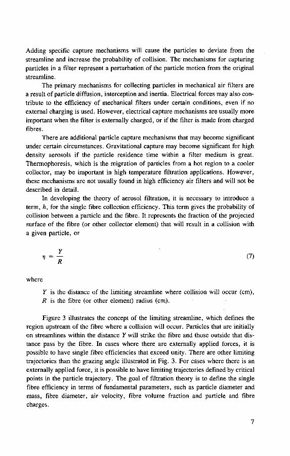
Adding specific capture mechanisms will cause the particles to deviate from the streamline and increase the probability of collision. The mechanisms for capturing particles in a filter represent a perturbation of the particle motion from the original streamline.
The primary mechanisms for collecting particles in mechanical air filters are a result of particle diffusion, interception and inertia. Electrical forces may also con-tribute to the efficiency of mechanical filters under certain conditions, even if no external charging is used. However, electrical capture mechanisms are usually more important when the filter is externally charged, or if the filter is made from charged fibres.
There are additional particle capture mechanisms that may become significant under certain circumstances. Gravitational capture may become significant for high density aerosols if the particle residence time within a filter medium is great. Thermophoresis, which is the migration of particles from a hot region to a cooler collector, may be important in high temperature filtration applications. However, these mechanisms are not usually found in high efficiency air filters and will not be described in detail.
In developing the theory of aerosol filtration, it is necessary to introduce a term, h, for the single fibre collection efficiency. This term gives the probability of collision between a particle and the fibre. It represents the fraction of the projected surface of the fibre (or other collector element) that will result in a collision with a given particle, or
where
Y is the distance of the limiting streamline where collision will occur (cm), R is the fibre (or other element) radius (cm).
Figure 3 illustrates the concept of the limiting streamline, which defines the region upstream of the fibre where a collision will occur. Particles that are initially on streamlines within the distance Y will strike the fibre and those outside that dis-tance pass by the fibre. In cases where there are externally applied forces, it is possible to have single fibre efficiencies that exceed unity. There are other limiting trajectories than the grazing angle illustrated in Fig. 3. For cases where there is an externally applied force, it is possible to have limiting trajectories defined by critical points in the particle trajectory. The goal of filtration theory is to define the single fibre efficiency in terms of fundamental parameters, such as particle diameter and mass, fibre diameter, air velocity, fibre volume fraction and particle and fibre charges.
7

r
2.2.1. Diffusional capture mechanism
Submicrometre particles rebound when struck by the energetic gas molecules surrounding them; the smaller the particle the greater the movement. The result is increasing three dimensional random movement called Brownian motion. When a concentration gradient occurs in different zones of the same aerosol, migration of small particles takes place away from zones of higher concentration to zones of lower concentration. The process, known as diffusion, depends on Brownian motion, being more vigorous for smaller particles, and a driving force that is proportional to the concentration difference between the migration zones. The net gain or loss of parti-cles gradually slows down in response to a lessening concentration gradient between the zones and ceases entirely when equilibrium is established. Although Brownian motion continues unabated, no further change in concentration occurs between the zones.
When particles diffuse toward a surface, such as a filter fibre, and deposit on it, the particle concentration in the air layer closest to the fibre becomes zero. This maximizes the concentration gradient between the fibre surface and the main body of the aerosol. Given sufficient time, the process could continue until all the particles diffuse to the collecting surface and none remain airborne. This principle is employed for the removal of submicrometre aerosol particles by HEPA filters.
When suspended particles are very small they tend to closely follow the curved streamlines around a single fibre, but they will be in vigorous Brownian motion. Therefore, when a streamline passes close to a fibre, the random particle movements around the streamline result in some of the particles striking the fibre and ceasing to remain airborne (Fig. 4(d)). The effect is to establish a concentration gradient between the zone close to the fibre and the bulk of the aerosol, which, in turn, results in particle diffusion in the direction of the fibre surface. The smaller the particles,
8
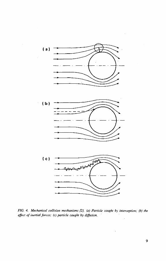
FIG. 4. Mechanical collision mechanisms [2], (a) Particle caught by interception; (b) the effect of inertial forces; (c) particle caught by diffusion.

the more vigorous will be the Brownian motion and the more effective will be filtra-tion by diffusion. Because the rate at which particles cross streamlines under the influence of diffusional force is slow relative to the time it takes for the particle to flow around the fibre, diffusional separation of small particles is enhanced by slower air velocity through a filter:
where
riD is the single fibre efficiency due to diffusion, Hs is the hydrodynamical factor corrected for slip (Eq. (3)), U is the air velocity inside the filter (cm/s), Re{f is the effective fibre radius (cm) (Eq. (5)), X is the mean free path of air, 6.53 X 10~6 cm at 1 atm1 and 20°C, D is the diffusion coefficient of the particle (cm2/s).
These terms are defined further by
1 — Of
where
V is the filter face velocity and
D = kTC
6ir nrp
where
k is the Boltzmann constant, T is the absolute temperature (K), H is the gas viscosity (Pa/s), rp is the particle radius (cm), C is the slip correction factor.
From Eq. (8), the collision efficiency for the diffusion mechanism increases as the particle radius, rp, decreases, the temperature, T, increases, the fibre volume
' 1 atmosphere (atm) = 101 325 Pa.
10

fraction, a, increases, the fibre radius, RF, decreases and the air velocity, U, decreases.
The theoretical model for diffusional collision assumes that the particles are infinitely small point particles. This is not rigorously correct, since the particles will collide with the fibre when within a radius of one fibre.
2.2.2. Inertia-interception collision mechanism
When the particle size increases the diffusional collision mechanism decreases and the inertial collision mechanism increases, as illustrated in Fig. 4(b). When par-ticles possess sufficient inertia, because of their mass relative to the mass of the con-veying gas molecules, they resist following the curvature of the air streams and collide with the fibre. The limiting streamline (defined by 7in Fig. 3) increases with increasing particle inertia. This effect becomes greater when the particle becomes larger or more dense and when the velocity of the air approaching the fibre is greater.
Unfortunately, the inertial collisional mechanism does not have a closed form analytical expression and must be computed by numerical methods of particle trajec-tories. Particle trajectories are computed for different values of Y until the limiting trajectory is found. The finite size of the particles is taken into account in these calcu-lations, since a collision occurs whenever a particle comes within one particle radius of the fibre collector.
Most of the modern filtration theories include a separate collision mechanism, known as the 'interception mechanism', that owes its existence to the finite size of particles. This mechanism assumes that particles have zero mass and collide with the fibre whenever the streamline comes within one particle radius of the fibre (Fig. 4(a)). Unfortunately, this theory has no physical basis, since finite sized parti-cles cannot have zero mass. In contrast to the situation with the diffusional collision mechanism, the finite size of the larger particles cannot be ignored.
Banks and Kurowski [13, 14] have shown recently that the inertial collision mechanism has the same form as the interception capture mechanism in the limit as particle inertia approaches zero. They showed excellent agreement between the inertial capture mechanisms and a perturbation series with increasing inertia terms. The first term in the perturbation series was identical to the term for the interception mechanism. Thus, the interception mechanism is actually an inertial collision mechanism in the limit of low particle inertia.
Since the filter efficiency found in typical HEPA filters increases extremely rapidly with increasing particle size or inertia, the low inertia particles are hardest to remove. Therefore, in order to model the particle penetration in HEPA filters, the inertial collision mechanism can be approximated by the first non-zero inertia term of the perturbation series. This first term is identical to the term for interception collision. Unlike the complete inertial collision mechanism, the first term represent-ing interception does have a closed form for single fibre collision efficiency:
11

Hs ^eff ^ ( ^eff ^
+ 2 ( 1 + ^ ( 1 + ^ ( 1 + ^
This equation shows that the inertia-interception collision efficiency increases with increasing particle radius, rp, decreasing fibre radius, RF, and increasing fibre volume fraction, aF . This equation also indicates no dependence on air velocity and requires experimental validation. Higher inertial terms are velocity dependent.
2.2.3. Electrical collision mechanism
Electrical capture mechanisms [9-11] are not normally significant in mechani-cal filters, but there are exceptions. For example, passing dry air through a HEPA filter may lead to a large electrostatic charge on the aluminium separators. In certain applications where the charge builds up, the spark potential could cause explosions and should be prevented. An approach described by Scholten and Letschert [15] is to connect a grounding wire to the aluminium separators. This type of charge buildup is expected to be much greater for filters made from polymeric fibres than for filters made from glass fibres. Polymeric fibres cannot bleed off the charge as rapidly as glass fibres, owing to their low electrical conductivity. Unintentional filter charging may result in a higher filter efficiency than in other environments where the filter does not build up a charge. A rapid decrease in filter efficiency with little change in pressure drop when testing polymeric filters with oil aerosols suggests the presence of an electrical charge on the filter.
Electrical forces can be intentionally applied to a filter to increase efficiency dramatically [15-18]. This can be accomplished by applying an electric field on the filter media with external electrodes, by precharging the aerosols with a corona dis-charge, or a combination of these two. For HEPA filters, the aluminium separators can conveniently serve as electrodes. Alternatively, an electrostatically charged filter can be made by using permanently charged fibres. There are advantages and disadvantages to both approaches. Charged fibre filters do not need external charging devices, but can suffer from charge deterioration. In contrast, externally charged filters do not suffer a loss in electrical charge, but require external charging devices. For application in HEPA filters, both types of electrically charged filters would yield large increases in filter efficiency because of the low air velocity through the filter media. All electrical capture mechanisms show large increases in particle collection with decreasing air velocities.
There are many different electrical collision mechanisms that can occur with externally charged filters, or filters that are made from permanently charged
12

fibres [16]. However, for mechanical filters the most likely collision mechanism is due to the force between charged filter media and charged particles and the force between charged filter media and polarized particles. The charge on the filter media could arise from the air friction, or from previously trapped charged particles. The single fibre efficiency term between charged particles and fibres is:
- n e Q C n m - l ^ T ( 1 0 )
where
n is the number of charges on the particle, e is the charge of one electron (coulomb), Q is the charge per unit length of fibre (coulomb/cm), C is the Cunningham slip factor,
and between charged fibres and polarized particles is:
2 e;' Q2r2C
where
ep is the dielectric constant of particles.
Single fibre collision efficiencies increase with decreasing air velocity and with increasing fibre charge. If the fibre charge disappears, then there will be no electrical capture mechanisms. Thus, to determine if electrical mechanisms are active in a given filter, it is necessary to neutralize the fibre charge (e.g. antistatic agent) or to increase the conductivity of the fibres so that charge cannot build up. Since both diffusional and electrical mechanisms decrease with increasing air velocity, it is not possible to use variations in air velocity to distinguish between the two mechanisms.
Electrical capture mechanisms may indicate erroneously high efficiencies in testing for certification if charged aerosols are used. Sodium chloride and uranine aerosols from nebulizing may have significant particle charge, which may build a charge in the filter and lead to overestimation of filter efficiency [16].
2.3. FILTER EFFICIENCY
Once the various collision mechanisms are identified, it is necessary to com-bine the mechanisms into a single collision efficiency term before the efficiency of the filter material is obtained [15-23].
13

To determine the single fibre collision efficiency for a combination of mecha-nisms, it is necessary to add the different mechanisms in the particle trajectory calcu-lations. It is not correct to add each of the single fibre collision efficiencies that correspond to a specific mechanism in order to obtain the single fibre efficiency for the combined mechanisms. There are usually cross terms that make the approach inaccurate. However, for the diffusional and the zero order inertial (i.e. interception) mechanisms, there are no cross terms and adding the single fibre efficiencies is equivalent to the single fibre efficiency of the combined mechanisms.
Thus,
VT = VD + Vi (12)
Adding the additional terms of the inertial mechanism or the electrical mechanisms would not be rigorously correct. However, this could be done as an approximation.
The total filter penetration can be determined by first computing the differen-tial change in particle concentration across a differential slice of the filter thickness. To do this the single fibre collision efficiency is multiplied by the number of fibres in a differential section of the filter mat and the particle concentration. The differen-tial change in particle concentration is then integrated over the filter thickness to yield the penetration of the filter medium:
( 2af L tt-jS \
p yi , ) ( 1 3 )
ir /?effC 1 - ocF) /
where
S is the 'sticking' coefficient.
In general filtration theory, it is often necessary to introduce a 'sticking' coeffi-cient' because not every particle that collides with a fibre will stick to the fibre. When a particle makes contact with a filter fibre, the particle is held to the fibre by Van der Waals force. For ultrafine particles, i.e. less than 10 fxm, the thermal energy can be too great for the weak sticking forces and re-entrainment is possible. Creep of ultrafine particles was studied by Kops et al. [24]. For very large particles or at high air velocities, particles may not stick to the fibre surface because their kinetic energy during collision exceeds the binding for adhesion. Theoretical and experimental studies show that particle bounce is only significant for particles larger than 5 ^m and at high velocities. For HEPA filters, the sticking coefficient for all particles is 1, within the region of maximum penetration.
Equation (13) determines the filter penetration for filter media and filter units. This equation can be used directly to compare experimental measurements. However, for comparisons with filter units, it is first necessary to determine the filter face velocity for the medium by:
14

Particle size
FIG. 5. Effects of inertia, diffusion and interception on the penetration-particle size curve [2],
A
where
F is the volumetric flow rate (m3/s), A is the total area of filter media (m2).
It is important to remember that Eq. (13) has only the first term of the inertial mechanism, i.e. the interception term. Because of this limitation, the equation is not valid for computing filter penetration for particles with significant inertia. For HEPA filters, this is not a serious restriction, since the filter face velocity is about 2 cm/s and the inertia is small for particles with maximum penetration. However, for sig-nificantly larger particles, the equation will predict higher penetrations than actually occur.
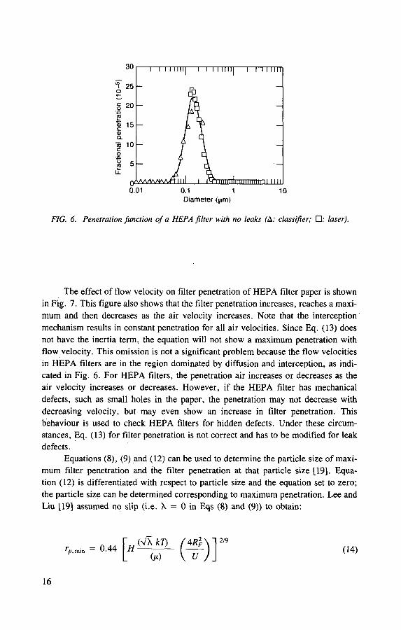
The results of many previous numerical computations provide a good under-standing of filter penetration governed by the diffusion, interception and inertial mechanisms. Figure 5 shows filter penetration as a function of particle size com-puted with the three mechanisms acting separately and together. This figure shows that there is a particle size region where diffusion is dominant and another where inertia-interception is dominant. There is also a particle size region within which all of the mechanisms have high levels of penetration, thereby leading to maximum penetration. The exact maximum point varies with fibre diameter, filter construction and flow velocity. These results are consistent with Eqs (12) and (13). It is important to note that this point of maximum penetration is independent of particle parameters. The particle size of maximum penetration will remain the same for all particles, whether they are low density oil aerosols or high density uranium aerosols. The minimum filterable particle size for nuclear grade HEPA filter papers is close to 0.1 mm when operated at the design flow of 2.5 cm/s. Figure 6 shows the experimental penetration of HEPA filters as a function of particle size for di-octyl-phthalate (DOP) aerosols.
15
I I I I llllj 1 I I I I lllj 1 I I I nil
ilil I II INI 0.01 0.1
Diameter (iim) 1 10
FIG. 6. Penetration function of a HEPA filter with no leaks (A: classifier; • : laser).
The effect of flow velocity on filter penetration of HEPA filter paper is shown in Fig. 7. This figure also shows that the filter penetration increases, reaches a maxi-mum and then decreases as the air velocity increases. Note that the interception' mechanism results in constant penetration for all air velocities. Since Eq. (13) does not have the inertia term, the equation will not show a maximum penetration with flow velocity. This omission is not a significant problem because the flow velocities in HEPA filters are in the region dominated by diffusion and interception, as indi-cated in Fig. 6. For HEPA filters, the penetration air increases or decreases as the air velocity increases or decreases. However, if the HEPA filter has mechanical defects, such as small holes in the paper, the penetration may not decrease with decreasing velocity, but may even show an increase in filter penetration. This behaviour is used to check HEPA filters for hidden defects. Under these circum-stances, Eq. (13) for filter penetration is not correct and has to be modified for leak defects.
Equations (8), (9) and (12) can be used to determine the particle size of maxi-mum filter penetration and the filter penetration at that particle size [19]. Equa-tion (12) is differentiated with respect to particle size and the equation set to zero; the particle size can be determined corresponding to maximum penetration. Lee and Liu [19] assumed no slip (i.e. X = 0 in Eqs (8) and (9)) to obtain:
( 1 4 )
16

<
/ /
/ /
c o Interception <o T <D c <0 CL
Linear velocity
FIG. 7. Effects of inertia, diffusion and interception on the penetration-linear velocity
curve [2].
then substituting this equation into Eq. (11):
Equations (14) and (15) will then give the maximum filter penetration without taking account of slip. The equations are useful for indicating trends, since, for HEPA filters, errors owing to neglect of slip are important.
Equation (14) shows that the most penetrating particle size becomes smaller with increasing air velocity, U, decreasing fibre radius, RF, and increasing fibre volume fraction, aF . Figure 8 shows good agreement between Eq. (14) and experimental measurements of a filter designed for different air velocities and fibre volume fractions.
2.4. FILTER LOADING
The most important operational property of HEPA filters after filter penetra-tion and pressure drop is particle loading capacity, which is important because it determines the useful life of HEPA filters. The behaviour of the filter, as a deposit of particles accumulates in the filter, depends on the particle size, whether the parti-cles are solid or liquid, the morphology of the particle deposits, the fibre volume fraction of the filter and the filter fibre diameter.
(15)
17

Solidity (n)
FIG. 8. Comparison of theory and experiment for the most penetrating particle diameter
(U„ = I(o ); 3 ( • ); 10 ( A j and 30 ( • ) cm/s; : predicted; D,: 11.0 ixm).
The difference between solid and liquid particles is that the solid particles tend to form a rigid particle deposit within the filter, while liquid particles can coalesce within the filter, then flow through the filter media and spray out upon exit. However, during the early stages of filter loading, both solid and liquid particles tend to remain on the collecting fibres. The main difference in the early stages of loading is morphology. Solid particles tend to form particle branches that extend from the fibre as new particles collide with previously trapped particles. In contrast, liquid particles tend to form a uniform layer around the fibre as the liquid drops coalesce. Solid particles can also form a more uniform deposit around the fibre, especially with added electrical forces.
A number of theoretical models have been developed to explain the observed increase in flow resistance and the increase in filter efficiency. Figure 9 shows the physical basis of three simple models to explain filter loading behaviour. The den-drite model represents the case where solid particles form particle branches that extend from the fibre surface. This model treats the particle branches as new filter fibres, using the same equation to describe the particle branches as the original fibre. The increasing fibre model treats the fibre deposits in terms of a larger fibre. Finally, the combined model represents a mixture of the two previous models.
The most applicable filter loading model for HEPA filtration is the dendrite model. This follows because most applications for HEPA filtration are for removing solid particles in a dry environment, which would lead to the formation of particle
18

(b)
(C)
Air flow
FIG. 9. Filter loading, (a) Dendrite model; (b) increasing fibre model; (c) combined model.
dendrites. The equation for describing the increase in flow resistance with increasing particle loading is:
A P - AP0 _ A , a , ( 1 6 )
AP0 r„ aF
where
AP is the filter airflow resistance after particle loading (Pa), AP0 is the filter airflow resistance for the clean filter (Pa), a p is the volume fraction of particles, a F is the volume fraction of fibres.
Equation (16) shows that the fractional increase in filter airflow resistance is directly proportional to the particle loading, ap , and the fibre radius, RF, and is inversely proportional to the particle radius, rp, and the fibre volume fraction, aF.
19
The inverse dependence of the increase in flow resistance on the fibre volume frac-tion is somewhat surprising at first, since it is common knowledge that loose filters with small fibre volume fractions have lower airflow resistance than do filters with large fibre volume fractions. This apparent disagreement is resolved when it is recognized that Eq. (16) represents the relative increase in airflow resistance com-pared with the initial value for a clean filter. Although the relative increase in flow resistance is lower for a filter with a large fibre volume fraction, the absolute flow resistance for a tightly packed filter (high aF) is still much higher than for a loosely packed filter (low aF).
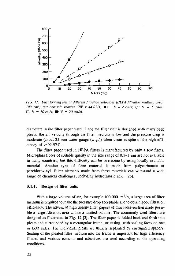
Applications of the model to experimental loading studies on HEPA filters show good agreement if the air velocities and masses deposited are low. Figure 10(a) shows experimental measurements of flow resistance for three different particle sizes. The figure illustrates that deposits of smaller particles raise the airflow resistance more than deposits of larger particles. By replotting the data as (AP — AP0) rp, all of the loading curves fall on the same curve, in agreement with theory (Fig. 10(b)). Results presented by Le Tourneau et al. [20] are also relevant and are given in Fig. 11.
An important feature of the filter loading theory is the ability to predict filter loadings in field applications if the size of the challenging particles is known. A laboratory test using one type of aerosol would then allow predictions to be made for any other type of aerosol.
3. CHARACTERISTICS OF FILTRATION SYSTEMS
The basic component of a filtration system in a nuclear facility is the HEPA filter. Although the designs of commercial units have been widely improved over many years, abnormal conditions often require the use of additional means of protec-tion and supplementary devices or modified designs [2, 25-27],
During accidents operating conditions may be far from normal, so that HEPA filters, even with reinforced protection, may be inadequate. For these very specific applications (such as severe accidents in PWRs), special designs have sometimes been proposed and these devices are described in Section 4.
3.1. HEPA FILTERS
When cleaning the air of radioactive or toxic contaminants, small particles must also be removed with a high degree of efficiency, as even small concentrations in the air can be harmful. HEPA filters are superior to common air filters for the removal of small particles (Table I) because of the very fine fibres ( < 1 yt.m in
20

Particle mass (kg)
Particle mass (kg)
FIG. 10. Filter loading theory, (a) Particle radius (in fim) — • : 0.025; A 1.00; O : 2. 75); (b) particle radius (r) (in /xm) — • : 0.25; A ; 1; Q: 2. 75.
2 1
800
7 0 0
P '
< 4 0 0 o P'
< 3 0 0
i 0.
200
100
0 •
0 1 0 2 0 3 0 4 0 5 0 6 0 7 0 8 0 9 0 1 0 0
MASS (mg)
FIG. 11. Dust loading test at different filtration velocities (HEPA filtration medium; area: 100 cm2; test aerosol: uranine (NF X 44 011); • : V = 2 cm/s; O: V = 5 cm/s; • : V = 10 cm/s; V = 20 cm/s).
diameter) in the filter paper used. Since the filter unit is designed with many deep pleats, the air velocity through the filter medium is low and the pressure drop is moderate (about 25 mm water gauge (w.g.)) when clean in spite of the high effi-ciency of >99.97%.
The filter paper used in HEPA filters is manufactured by only a few firms. Microglass fibres of suitable quality in the size range of 0.5-1 /xm are not available in many countries, but this difficulty can be overcome by using locally available material. Another type of fibre material is made from polycarbonate or perchlorovinyl. Filter elements made from these materials can withstand a wide range of chemical challenges, including hydrofluoric acid [26].
3.1,1. Design of filter units
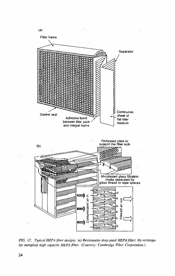
With a large volume of air, for example 100 000 m3/h, a large area of filter medium is required to make the pressure drop acceptable and to obtain good filtration efficiency. The advent of high quality filter papers of thin cross-section made possi-ble a large filtration area within a limited volume. The commonly used filters are designed as illustrated in Fig. 12 [2], The filter paper is folded back and forth into pleats and surrounded by a rectangular frame, or casing, with sealing faces on one or both sides. The individual pleats are usually separated by corrugated spacers. Sealing of the pleated filter medium into the frame is important for high efficiency filters, and various cements and adhesives are used according to the operating conditions.
22

TABLE I. COMPARISON OF AIR FILTERS BY REMOVAL EFFICIENCY FOR VARIOUS PARTICLE SIZES
Removal efficiency (%) for a particle size of Group Efficiency
0.3 fim 1.0 fim 5.0 jim 10.0 Aim
I Low 0-2 10-30 40-70 90-98
II Moderate 10-40 40-70 85-95 98-99
III High 45-85 75-99 99-99.9 99.9
HEPA Extreme 99-97 minimum >9.99 100 100
In some cases, sealing is achieved by compressing the ends with fine fibre pads. The filter is provided with sealing gaskets on one or both ends, depending on the method of filter installation. Some types of filter have no spacers, the spacing being achieved by pleating the filter paper in a special way. Deep pleat filters made without spacers are not strong enough for use with contaminated exhaust and there is no increase in their dust loading capacity with atmospheric aerosols [2]. Various manufacturing designs allow a wide range of flow capacities.
A combination of suitable materials in the different parts of the filter guaran-tees the properties necessary for all normal and some abnormal operating conditions. The usual construction materials used in HEPA filters are described in what follows.
3.1.1.1. Filter medium
The most commonly used filter media are glass, perchlorovinyl, cellulose acetate and plastic fibres, and ceramics. The earliest high efficiency fibrous filters were built up using several layers of fibre pads, but currently the usual filter medium is paper of various compositions.
(a) Glass fibre paper
With the development of advanced techniques for making glass fibre paper, this type of filter medium has become very common. The fibres have, to a large extent, diameters < 1 /̂ m, and a special paper making process produces a suitable type of paper. The pleating must be carried out carefully to avoid cracking at the folds — often a source of increased particulate penetration. This paper has good heat resistance and can withstand a temperature of 350°C, but its strength is markedly reduced above 200°C, probably due to burnoff of the binder. It is non-inflammable,
23
Gasket seal Adhesive bond
between filter pack • and integral frame
Separator
Continuous sheet of fiat filter medium
Perforated plate to support the filter rack
Minipleated glass filtration media separated by
glass thread or tape spaces
FIG. 12. Typical HEPA filter designs, (a) Rectangular deep pleat HEPA filter; (b) rectangu-lar minipleat high capacity HEPA filter. (Courtesy: Cambridge Filter Corporation.)
24

which means that even if a spark ignites the dust in the filter, the filter medium itself does not contribute to the fire. Local melting, with a decrease in efficiency, was observed in tests [28]. Glass fibre papers given waterproofing treatment have good efficiency even under high humidity conditions. They also have good resistance to most chemicals and to corrosive atmospheres.
(b) Perchlorovinyl and cellulose acetate paper
Fibrous polymeric perchlorovinyl (FPP) material consists of superfine perchlorovinyl fibres 1.5-2.5 /xm in diameter. This material is hydrophobic and is used in systems where the operating temperature is less than 60°C. In higher temperature systems (up to 150°C), fibrous polymeric acetate (FPA) polymer material is used; it is manufactured from cellulose acetate (fibre diameter of 1.5 pan). However, owing to the 'wetting' propensity of FPA, usage is restricted to relative humidities not higher than 80%.
Using these materials, high efficiency aerosol filters of a frame design can be produced. The filters are a set of all-stamped, corrugated, wedge shaped frames and separators made of vinyloplast. These filters have a flow resistance of 300-450 Pa and are placed in special cells under a layer of concrete shielding. The cleaning efficiency for aerosols of particulate sizes 0.1-0.2 ^m is not less than 99.9%. The dust holding capacity of these filters reaches 70-80 g/m2 [29].
(c) Thermoplastic fibres
These fibres are made of polyethylene, nylon and polystyrene, the latter material being used in a commercially available HEPA filter. The fibres have diameters ranging between 0.5 and 1.5 fim and the filter medium can be moulded into a frame of the same material. For disposal of the used filter, the whole unit can be dissolved and after evaporation the volume is reduced to a minimum. The plastic fibre filter also offers a method of recovering valuable radioactive components. The medium has good resistance to chemical attack, but has low heat resistance. For polystyrene the temperature is limited to 80°C. The material is inflammable and its ignition temperature is about 120°C.
(d) Ceramics
The need for filters capable of withstanding temperatures above 500 °C for prolonged periods has resulted in the use of ceramic material, often aluminosilicate. This is available in the form of fibres that can be used as a thin paper or as a deep bed, but not yet in a low priced unit. The strength and chemical resistance is as good as that of glass and, in addition, the material can withstand temperatures up to 1000°C. Since mild steel cannot be used in the frame at this high temperature, the filter units are fabricated entirely of ceramic materials.
2 5

3.1.1.2. Frame (filter casing)
Frames are generally made of plywood, steel, reinforced plastic, aluminium, or ceramics.
Plywood frames are of low cost construction and are the most commonly used. Disposal of dust loaded filters is easy, by compression or incineration. The thickness of the plywood should be 0.75 in (20 mm) to ensure leaktightness of the frame, to give rigidity and to resist compression forces when the filter is clamped to the mount-ing frame. Exterior grade plywood is needed for good moisture resistance. To meet fire protection requirements, fire retardant plywood is specified (pressure impregna-tion is used to ensure good impregnation). When such frames are used in tropical areas, it may be necessary to include treatment to increase resistance to fungal growth. The temperature should not exceed 100°C. Wood particle board is also used.
Steel frames are used for high temperature applications and when a non-inflammable construction is needed. Such frames can withstand operating tempera-tures of up to 500°C. Cadmium plated carbon steel is usually used to avoid corro-sion. Mild steel coated with epoxy paint is also resistant to moisture. Filters with stainless steel frames are much more expensive, costing about twice as much as those with wooden frames.
Reinforced plastic and ceramics are used in combination with filter media of corresponding material.
3.1.1.3. Spacers or separators
The materials used for spacers or separators are kraft paper, aluminium, plas-tic, stainless steel, ceramics, or, in the minipleat design, glass fibre threads. Kraft paper separators are the least expensive, but they have poor resistance to heat, humidity and chemical attack. Aluminium spacers are generally more useful. They can withstand a temperature of at least 300°C and have good water resistance. Their chemical resistance is relatively good, except for streams with a high caustic content. Plastic has poor heat and fire resistance, while stainless steel separators are extremely expensive. Spacers are sometimes provided with a soft edge on one side over which the filter medium can be safely folded.
3.1.1.4. Adhesive or cement
The adhesives generally used are rubber based, epoxy resin, silicone, polyester resin, plastic compounds, silicate, or refractory cement. Rubber based adhesive is most commonly used for normal temperatures. If the filter is intended for continuous operation at higher temperatures, the limiting service temperature should be given by the manufacturer. On the other hand, plastic adhesives have limited temperature
26
resistance. Silicate or refractory cements, which are high temperature adhesives, should only be used when necessary because temperature resistance is not always combined with good sealing properties. Glass fibres, in the form of a pad, are some-times used instead of adhesive as a passive seal between the filter pack and the frame. Such a design is very sensitive to mechanical damage, for example during transportation.
3.1.1.5. Gaskets
The materials used for gaskets are rubber, neoprene, teflon, silicone, glass fibres, or mineral fibres. While rubber gaskets are not suitable for temperatures above 70°C, neoprene can withstand slightly higher temperatures. Closed cell neoprene gaskets are suitable, the recommended gasket size being 6 mm thick and 19 mm wide. Gaskets should have cut surfaces on both faces because the 'natural skin' produced by moulding tends to bridge discontinuities or defects in the sealing surfaces. A one piece moulded gasket has better tightness characteristics. Mineral and glass fibres are used for high temperature filters.
3.1.2. Properties of filter units
3.1.2.1. Air flow capacity and geometrical size
In spite of the lack of any formal standardization, HEPA filters are traditionally of internationally accepted sizes. The different sizes are related to normal airflow (Table II). With the development of new filter papers, the air capacity has increased, but generally the rated capacity of the clean filters are given for a pressure drop of 250 Pa.
Smaller filters are made for use in shielded cells or glove boxes. The filter area increases from 20 m2 of paper in standard folded filters to 45 m2 in minipleated filters. The advantage is a lower pressure drop at standard flow or increased capacity for existing housings. The disadvantage is that minipleated filters are limited in pressure drops to about 6500 Pa.
3.1.2.2. Pressure drop
As mentioned in Section 2.1, there is normally a linear relationship between airflow and pressure drop. A standard filter is usually designed for a pressure drop of 25 mm w.g. at rated air flow. At 50% of rated airflow, the pressure drop is 12.5 mm w.g. and at 150% airflow the pressure drop is 37.5 mm w.g. When design-ing the ventilation system, all pressure drops in grids, ducts and filters have to be considered. Allowance must be made for an increase in the pressure drop because
27
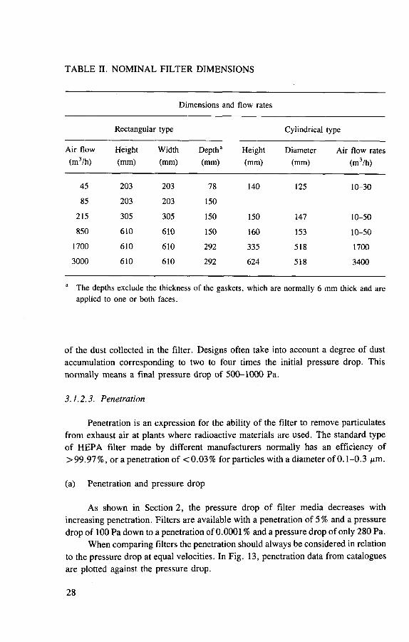
TABLE II. NOMINAL FILTER DIMENSIONS
Dimensions and flow rates
Rectangular type Cylindrical type
Air flow (m3/h)
Height (mm)
Width (mm)
Depth3
(mm) Height (mm)
Diameter (mm)
Air flow rates (m3/h)
45 203 203 78 140 125 10-30
85 203 203 150
215 305 305 150 150 147 10-50
850 610 610 150 160 153 10-50
1700 610 610 292 335 518 1700
3000 610 610 292 624 518 3400
a The depths exclude the thickness of the gaskets, which are normally 6 mm thick and are applied to one or both faces.
of the dust collected in the filter. Designs often take into account a degree of dust accumulation corresponding to two to four times the initial pressure drop. This normally means a final pressure drop of 500-1000 Pa.
3.1.2.3. Penetration
Penetration is an expression for the ability of the filter to remove particulates from exhaust air at plants where radioactive materials are used. The standard type of HEPA filter made by different manufacturers normally has an efficiency of >99.97%, or a penetration of <0.03% for particles with a diameter of 0.1-0.3 jim.
(a) Penetration and pressure drop
As shown in Section 2, the pressure drop of filter media decreases with increasing penetration. Filters are available with a penetration of 5% and a pressure drop of 100 Pa down to a penetration of 0.0001 % and a pressure drop of only 280 Pa.
When comparing filters the penetration should always be considered in relation to the pressure drop at equal velocities. In Fig. 13, penetration data from catalogues are plotted against the pressure drop.
2 8

Pressure drop (mm w g.)
FIG. 13. Penetration versus pressure drop for various filter media.
(b) Penetration and air velocity
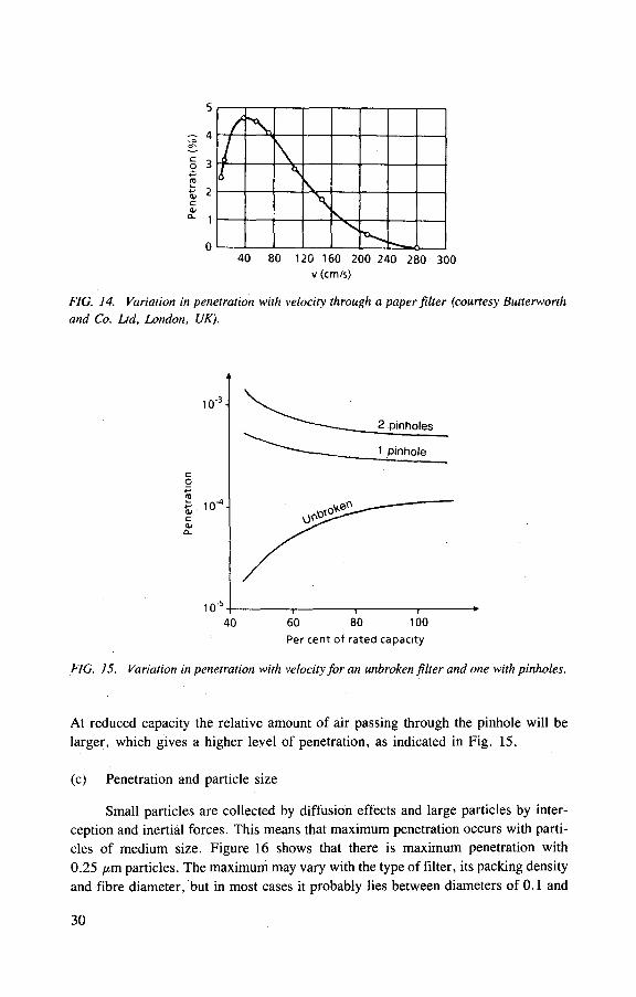
As was already mentioned in Section 2, the main mechanism causing particles to be caught in the filter is influenced by the velocity of air. At low speed, diffusion is effective and penetration is low. At a higher speed, diffusion effects decrease and inertial forces predominate. Peak penetration occurs at a velocity where the diffusion effect is low and the inertial forces are still small (Fig. 14). This peak appears at a velocity of about 10-40 cm/s. The smaller the particle, the greater is the velocity at which peak penetration occurs.
As the speed through the filter paper in a standard HEPA filter is about 2 cm/s, it is obvious that the penetration will increase as long as the airflow through the filter is increased within practical limits (Fig. 15). This is true as long as the filter has no leakage through pinholes or cracks in the folds, or in the sealing between the filter paper and the frame.
When there is a pinhole in the filter, part of the air will pass through that hole practically unfiltered. However, the filter will meet specifications for a high effi-ciency filter because the filter paper is normally so good that the specified penetration allows for some pinholes. Although this is the case at rated capacity, it is not always so at reduced capacity, as discussed in Section 2.3. Figure 15 shows the penetration increases as the airflow decreases [2]. This phenomenon can be explained by the difference between the resistance of the filter paper itself and that of the pinhole. The resistance of the filter paper is a linear function of the air velocity, but turbulent air-flow through the pinhole gives a resistance that varies with the square of the velocity.
2 9
/ / \ I 40 80 120 160 200 240 280 300
v (cm/s)
FIG. 14. Variation in penetration with velocity through a paper filter (courtesy Butterworth and Co. Ltd, London, UK).
P e r c e n t of r a t e d c a p a c i t y
FIG. 15. Variation in penetration with velocity for an unbroken filter and one with pinholes.
At reduced capacity the relative amount of air passing through the pinhole will be larger, which gives a higher level of penetration, as indicated in Fig. 15.
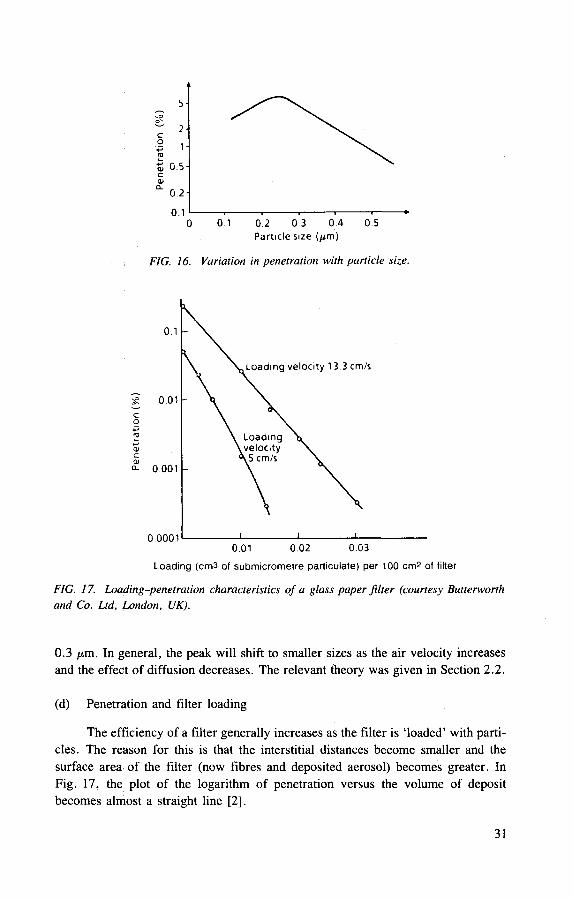
(c) Penetration and particle size
Small particles are collected by diffusion effects and large particles by inter-ception and inertial forces. This means that maximum penetration occurs with parti-cles of medium size. Figure 16 shows that there is maximum penetration with 0.25 /*m particles. The maximum may vary with the type of filter, its packing density and fibre diameter, but in most cases it probably lies between diameters of 0.1 and
30
5 0.5-c 01
0 . 2 -
0.1 r . . 1 1 • 0 0 1 0.2 0 3 0 4 0 5
Particle size (^m)
FIG. 16. Variation in penetration with particle size.
Loading (cm3 of submicrometre particulate) per 100 cm2 of filter
FIG. 17. Loading-penetration characteristics of a glass paper filter (courtesy Butterworth and Co. Ltd, London, UK).
0.3 //.m. In general, the peak will shift to smaller sizes as the air velocity increases and the effect of diffusion decreases. The relevant theory was given in Section 2.2.
(d) Penetration and filter loading
The efficiency of a filter generally increases as the filter is 'loaded' with parti-cles. The reason for this is that the interstitial distances become smaller and the surface area of the filter (now fibres and deposited aerosol) becomes greater. In Fig. 17, the plot of the logarithm of penetration versus the volume of deposit becomes almost a straight line [2],
31

3.1.2.4. Dust holding capacity
The dust holding capacity is defined as the amount of dust collected in the filter for a defined increase of pressure drop over the filter. Although highly dependent on the dust size distribution, the dust capacity of a HEPA filter is about 1 kg of dust for an acceptable pressure drop, i.e. between 500 and 1000 Pa at a standard airflow of 1700 m3/h.
Comparable data for dust holding capacities are very difficult to obtain from filter manufacturers. Most values are obtained from accelerated tests, sometimes with a test dust that is not relevant to the conditions under which the filter will operate (see Fig. 18). In this figure, the curves refer to the following test conditions:
Curve Test dust , , 3, Time Size Concentration Reference (Aim) (mg/m3) l m C (in Ref. [30])
A Natural settled dust 5.5 200 6 h [13]
B Prefiltered dust 2.0 40 15 h [13]
C NaCl fume 0.5 [13]
1 Cottrell precipitate 35 23 h [14]
without linters
2 Atmospheric aerosol < 1 0.05 1 a [10]
3 Carbon black [15]
1000
Dust load (g)
FIG. 18. Pressure drop increase for various dusts accumulated in filters (A: natural settled
dust (5.5 ixm); B: prefiltered dust (2.0 ixm); C: NaCl fume (0.5 fim); 1: Cottrell precipitate
without linters; 2: atmospheric aerosol; 3: carbon black (0.5-2.5 ixm)).
32

The tests were performed using glass fibre filters with efficiencies of more than 99.97% and a rated capacity of 1700 m3/h. By comparing curves A-C, we see that a filter is clogged more rapidly by small particles. Curves 1 and 3 are based on data given by manufacturers.
It is obvious that the curves in Fig. 18 reflect the difference between dust properties, rather than a difference in the behaviour of the filter units tested. A com-parative test is preferred in order to highlight differences between filters. In Ref. [2], a test of four filters from various manufacturers is reported. All were exposed to atmospheric aerosols with a mean concentration of about 0.05 mg/m3. Three of the filters showed the same characteristics, these being glass paper filters with a rated capacity of 1700 m3/h. After about one year, the pressure drop had increased to 500 Pa and the load was then 700 g (curve 2, Fig. 18). One filter accumulated only 450 g, but it had a slightly different design. Filters of traditional design had about the same load/pressure drop characteristic. There did not seem to be any simple correlation between dust holding capacity and filter area within the same filter unit sizes.
3.1.2.5. Resistance to overpressure, heat, fire, humidity and chemical attack
The requirements for a filter depend upon the conditions under which the filter will operate. It is often the extraordinary situations, rather than normal conditions, which determine the demands.
By combining suitable construction materials for filter media, separators, frame, adhesive and gasket, the properties of the complete filter can be determined. The characteristics of some materials are listed in Table III [2].
With regard to chemical resistance, the variety of chemical constituents and concentrations and other conditions, such as temperature and humidity, always make the choice of material difficult. In many cases, the only way is to test the different materials. Some basic characteristics of various materials are considered below:
— Glass filter medium is the best general medium, but deteriorates through the action of hydrogen fluoride (HF) and caustic stream contents.
— Aluminium separators are generally useful, but are susceptible to high caustic stream content. Plastic can be used in most atmospheres, but is poor in streams with a high vapour content.
— Wooden frames cannot withstand high concentrations of chemicals. Cadmium plated steel is relatively good, but reinforced plastic should be chosen for resistance to strong chemical attack, except when a high organic vapour con-tent is expected. The adhesive has to be chosen in conformity with the other materials of the filter. For high organic vapour content, silicate adhesive should be used instead of rubber or plastic based adhesive. When high chemi-cal stability is required in combination with high heat resistance, a mechanical seal can be used.
33
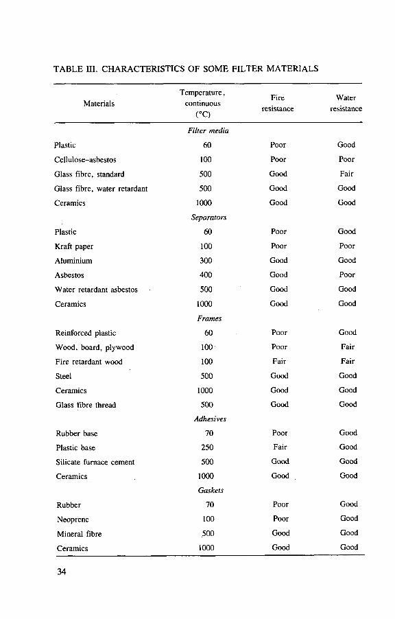
TABLE III. CHARACTERISTICS OF SOME FILTER MATERIALS
Materials Temperature,
continuous (°C)
Fire resistance
Water resistance
Filter media
Plastic 60 Poor Good
Cellulose-asbestos 100 Poor Poor
Glass fibre, standard 500 Good Fair
Glass fibre, water retardant 500 Good Good
Ceramics 1000 Good Good
Separators
Plastic 60 Poor Good
Kraft paper 100 Poor Poor
Aluminium 300 Good Good
Asbestos 400 Good Poor
Water retardant asbestos 500 Good Good
Ceramics 1000 Good Good
Frames
Reinforced plastic 60 Poor Good
Wood, board, plywood 100 Poor Fair
Fire retardant wood 100 Fair Fair
Steel 500 Good Good
Ceramics 1000 Good Good
Glass fibre thread 500 Good Good
Adhesives
Rubber base 70 Poor Good
Plastic base 250 Fair Good
Silicate furnace cement 500 Good Good
Ceramics 1000 Good Good
Gaskets
Rubber 70 Poor Good
Neoprene 100 Poor Good
Mineral fibre 500 Good Good
Ceramics 1000 Good Good
34

— Rubber and neoprene gaskets should be avoided when high organic vapour content is expected. Mineral fibres have a high degree of chemical stability.
— Ceramic filters, used for high temperature conditions, are resistant to most chemicals, except HF.
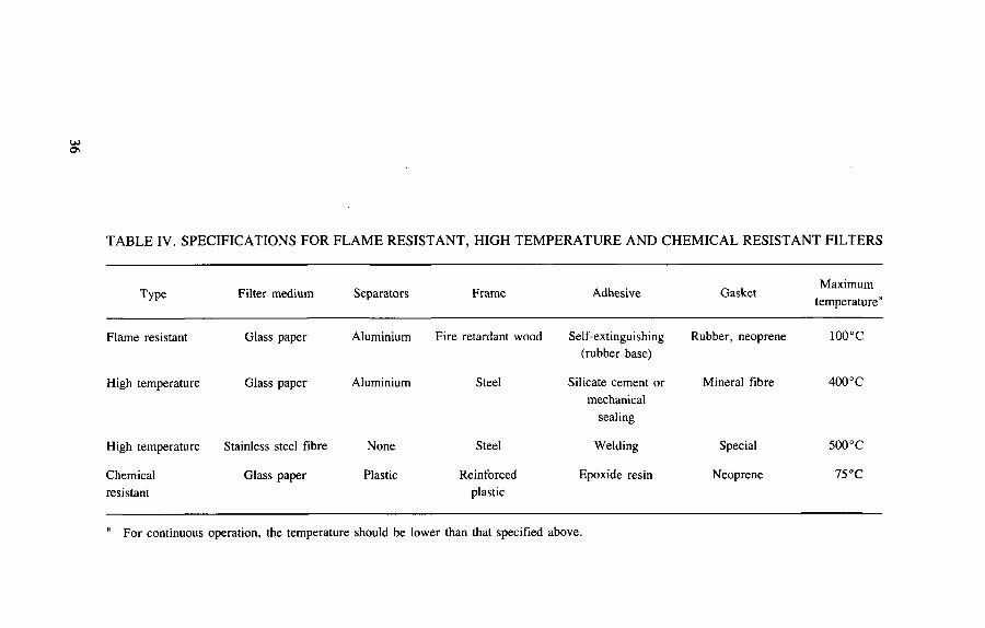
For both manufacturer and user it is advantageous to standardize the combina-tions of materials. If only a few types of filter are used, the number of filters to be stored can be reduced and the purchasing routine simplified. For most purposes, the filter must only operate at room temperature, and chemical constituents will appear only at very low concentrations in the stream. For safety reasons, a certain degree of fire resistance has to be specified. It is not economically feasible to have com-pletely fireproof filters when the risk of fire in the plant is moderate. A fireproof filter is more expensive and the disposal costs are also higher. What is usually required is that the filter should not support fire or that it should be flame resistant. Specifications for a flame resistant filter are suggested in Table IV. Such a filter can withstand the humidity occurring in normal plants. When a filter operates at elevated temperatures, or when there is a high fire risk, a high temperature filter is required.
Special attention should be paid to the high fire risk that exists during the han-dling of pyrophoric metals and inflammable solvents, or when serious radiological consequences could occur in the event of a filter fire. In such cases, a high tempera-ture filter is preferable even if the normal operating temperature is low. The high temperature filter has both good fire resistance and good humidity resistance. If a mechanical seal is used a filter efficiency test should be performed both at delivery and in situ.
The high temperature filter has fairly good chemical resistance. If, however, the chemical attack is strong, the steel frame will not be resistant enough. Where the exhaust ducts, for the same reason, are made of plastic, there is no need for a high temperature filter; a chemical resistant filter of plastic can be used instead. An exam-ple of such a filter is given in Table IV. A plastic filter cannot be used when there is a high organic vapour content in the stream.
When pressure rises are expected, there are specific design modifications pro-posed by manufacturers to increase the pressure resistance of common HEPA filters. Classic HEPA filter design allows operation under high relative humidity conditions with no damage because of the hydrophobic pretreatment of the filter media, though this is not suitable for liquid droplet removal.
In cases where liquid aerosols are present in air or can form during the opera-tion of process equipment, two versions of cleaning are possible, the preliminary heating of gases, or the usage of high efficiency, self-cleaning filters. The latter type are 'FARTO$' filters, equipped with superfine glass fibres (Fig. 19). These filters can operate continuously when filtering liquid aerosols. As a rule, they have a filter-ing bed thickness of up to 10 mm.
35
OJ ON
TABLE IV. SPECIFICATIONS FOR FLAME RESISTANT, HIGH TEMPERATURE AND CHEMICAL RESISTANT FILTERS
Type Filter medium Separators Frame Adhesive Gasket Maximum
temperature3
Flame resistant Glass paper Aluminium Fire retardant wood Self-extinguishing Rubber, neoprene 100°C (rubber base)
High temperature Glass paper Aluminium Steel Silicate cement or Mineral fibre 400°C mechanical
sealing
High temperature Stainless steel fibre None Steel Welding Special 500°C
Chemical Glass paper Plastic Reinforced Epoxide resin Neoprene 75°C resistant plastic
a For continuous operation, the temperature should be lower than that specified above.

Air inlet
FIG. 19. 'FARTOS' C-500 type filter unit (1: connecting piece (nozzle) for sample taking and pressure drop measurement (before the filter); 2: air inlet; 3: device for washing the filter mat; 4: cover; 5; connecting piece (nozzle) for sampling and pressure drop measurement (after the filter); 6; air outlet; 7: vessel; 8; filter; 9: perforated cylinder; 10; liquid drain connection).
The characteristics of the FARTOS filter [31] are:
— bulk density of fibre packing in a bed of 100 kg/m3, — surface density of 0.6 kg/m2 , — average hydrodynamic fibre diameter of 3.0-3.5 ^m.
When loading with solid particles, the pressure drop will increase continuously and, in this case, the FARTOS filter units can be regenerated by spraying water or other solutions containing chemical agents. After drying the filter material, by blow-ing air through the unit, the filter can again be used. The effect of repeated regenera-
3 7

tions on filter efficiency was investigated by several laboratories [32], The filter efficiency is about 99.9% under self-cleaning and 99.99% under loading conditions.
3.1.2.6. Mechanical resistance
A high efficiency particulate filter must be constructed of high quality filter media and care must be taken to prevent leakage. It is also important for the filter to have the mechanical strength to withstand transportation, rough handling and a variety of operating conditions.
Under operating conditions the pressure drop over the filter may rise to 50-100 mm w.g. If the filter is clogged with dust, the maximum pressure drop to which the filter can be exposed is the total static pressure developed by the fan in the system. In a general ventilating system, the total head of the fan is usually 100-200 /xm w.g. The ability to withstand a pressure drop depends on the depth of the filter and cross-sectional area. A good filter with a face size of 610 mm X 610 mm may withstand a pressure drop of < 500 mm w.g. for a depth of 150 mm and of < 1000 mm w.g. for a depth of 292 mm. The 292 mm deep filter is usually specified to withstand a pressure drop of 500 mm w.g. minimum. Conditions such as pulsating airflow resulting from air turbulence, temporary variation in fan pressure or vibration of the filter mounting framework may cause strain to a filter installation. If the filter is damaged, the unfavourable conditions should be eliminated by choosing a proper fan for the operating characteristics of the plant and by proper design of the duct upstream of the filters. Vibrating ducts should be adequately supported.
3.1.2.7. Ageing of filter inserts
The operating efficiency of HEPA filters is monitored in situ by test aerosol penetration measurements. It is possible, however, that factors such as temperature, radiation, vibration and chemical effects may result in an ageing process which could reduce filter strength and safe operation, especially under accident conditions. This is likely to be most important for secondary filters that have long in-plant lives as a result of their low particulate loading.
Work carried out in the United Kingdom [33] on used HEPA inserts has shown that although paper tensile strength does decrease with in-service use, only filters used in very aggressive environments (fume cupboard extract) show a deterioration below the value required by the purchasing specification for new units. Other tests showed that water repellent paper retains its strength better than does non-repellent paper. There was no connection between activity levels on the filters and changes in media physical properties.
At present no definitive information is available on filter lifetime, as this varies with the nature of the exhaust gases being treated. Operators should, however, be
38

aware of the ageing process and take measures to ensure that filter inserts are changed before they deteriorate below an acceptable level.
3.2. PROTECTION OF HEPA FILTERS
In a ventilation system, conditions can prevail that exceed the structural strength of a standard HEPA filter. This can be the case under accident conditions. Maintaining the integrity of the filter system requires countermeasures to protect the filter medium. To achieve this, two options are possible:
(1) Alter the conditions, using upstream devices, so that a standard HEPA filter can operate satisfactorily in modified conditions. Some devices are described in the following paragraphs.
(2) Improve the strength of the filter. This will usually require special designs for particular applications (see Section 4.3.2.2 on the filters in containment vent lines).
3.2.1. Prefilters
The dust loading capacity of a HEPA filter is limited, depending on the proper-ties of the dust and the pressure drop permitted, but, in general, for a standard size HEPA filter of 609 mm X 609 mm x 292 mm, the capacity is not more than 1 kg.
To avoid frequent replacement of HEPA filters, a prefilter with a moderate efficiency is used. The cost effectiveness has to be judged on a case by case basis. One advantage may be that a prefilter does not require a costly in situ test.
In Europe, prefilters are classified according to nine groups, EU-1 to EU-9; their efficiencies are given in Ref. [30]. There is also a specific nomenclature in the United States of America.
For the lower numbers in the European classes, the efficiency is measured using the American Society of Heating, Refrigerating and Air Conditioning Engineers (ASHRAE) dust spot test. Comparative efficiencies for this test, the atmospheric dust and the DOP tests, are illustrated in Fig. 20. In Table I, compari-son of the removal efficiency of some groups is given as a function of particle size. Statements on filtration efficiency must include information on the test method.
To protect a HEPA filter against high dust loading, only high efficiency prefilters are suitable, i.e. a dust spot efficiency of >70%. Lower efficiencies will not be economic. A rolling filter can have advantages in preventing plugging in the event of a fire [34].
3 9

ASHRAE synthetic dust
70 80 85 95 ASHRAE atmospheric dust
20 30 50 70 80 90 95 98 DOP or similar test
m i i a r 10 20 30 40 50 60 70 80 90 95 99.99
FIG. 20. Approximate comparison of filter efficiencies using various test methods.
3.2.2. Demisters
HEPA filters are affected seriously by water loading. When free water droplets are expected, protection by a demister is required, especially for post-accident cleanup. Various designs of demisters are available commercially and, in general, high efficiency demisters made from stainless steel fibres are preferable. Under extremely wet conditions, a wave plate demister may be useful to disentrain the bulk of the water droplets. Care is required to prevent flooding and re-entrainment [35],
3.2.3. Other devices
Additional protection against dust and water droplets can be necessary to pro-tect a HEPA filter against other potential damage. Possible protection devices are given as examples below:
— Spark arresters: to protect against sparks that can burn through the filter medium;
— Dampers: to protect against high airflows, e.g. created by tornadoes; — Explosion valves: to protect against shock waves; — Scrubbers: to protect against reactive chemicals; — Coolers: to protect against high temperatures, especially in the event of
accidents; — Sprinklers: also to decrease the air temperature, but additional demisters are
required; — Heaters: to lower the relative humidity. .
3.2.4. System design
Extreme conditions for HEPA filters can frequently be avoided by appropriate design and layout of the filter system. For example, a long duct between the fire and
40

the filter may cool the air by natural convection. Another possible solution is to build two HEPA filter stages in series and to dilute between the stages with fresh air. The first stage may then deteriorate, but the second remains intact [36],
A solution used at some sites in the USA is a multiple filter bank. The first stages may be destroyed, but they will then act as a protection for the last stages. Potential failure mechanisms for filtration systems should be taken into account throughout the design process.
4. USE OF AEROSOL FILTERS IN NUCLEAR FACILITIES
4.1. INLET AIR FILTERS
In many cases it is important to use inlet air filters, since inactive aerosols in the incoming air may be filtered in the exhaust air filter system and thus reduce the operating lifetime of these filters. Both the operating cost of the exhaust filter system and the cost of disposal will increase (see Section 8). The inlet opening should be protected against weather conditions, i.e. rain, snow, etc. For system reliability, adequate fan redundancy should be included. Inlets should be sited in such a way as to minimize the risk of recycling ventilation exhaust gases.
If required, the inlet filter system can be built up in several stages. The first stage could be a self-winding prefilter. This type of filter has a high dust loading capacity and an acceptable level of efficiency for all particles > 5 /xm. The second stage could be a filter classified as EU-7 [30] or better. Bag filters are often used instead of EU-7 type filters. This type of filter is cost effective and has a high level of efficiency . In addition, droplet separation and heating could be used to reduce humidity if air conditioning is necessary.
4.2. EFFLUENT AIR FILTRATION FOR NORMAL ENVIRONMENTAL CONDITIONS
Normal environmental conditions imply operation under conditions close to ambient witliout any significant increase in temperature, pressure, humidity, radia-tion and corrosive gas content or incident or accident conditions.
4.2.1. Laboratory space ventilation
All air from a radiological laboratory has to pass through a filter system. In the absence of glove boxes, fume hoods, etc., all of the laboratory air will be
4 1
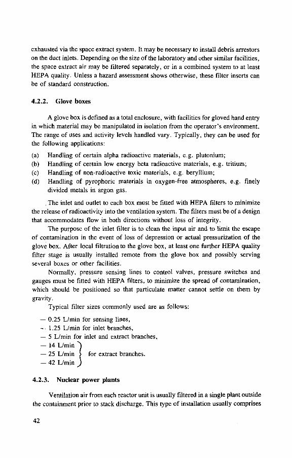
exhausted via the space extract system. It may be necessary to install debris arrestors on the duct inlets. Depending on the size of the laboratory and other similar facilities, the space extract air may be filtered separately, or in a combined system to at least HEPA quality. Unless a hazard assessment shows otherwise, these filter inserts can be of standard construction.
4.2.2. Glove boxes
A glove box is defined as a total enclosure, with facilities for gloved hand entry in which material may be manipulated in isolation from the operator's environment. The range of uses and activity levels handled vary. Typically, they can be used for the following applications:
(a) Handling of certain alpha radioactive materials, e.g. plutonium; (b) Handling of certain low energy beta radioactive materials, e.g. tritium; (c) Handling of non-radioactive toxic materials, e.g. beryllium; (d) Handling of pyrophoric materials in oxygen-free atmospheres, e.g. finely
divided metals in argon gas.
The inlet and outlet to each box must be fitted with HEPA filters to minimize the release of radioactivity into the ventilation system. The filters must be of a design that accommodates flow in both directions without loss of integrity.
The purpose of the inlet filter is to clean the input air and to limit the escape of contamination in the event of loss of depression or actual pressurization of the glove box. After local filtration to the glove box, at least one further HEPA quality filter stage is usually installed remote from the glove box and possibly serving several boxes or other facilities.
Normally, pressure sensing lines to control valves, pressure switches and gauges must be fitted with HEPA filters, to minimize the spread of contamination, which should be positioned so that particulate matter cannot settle on them by gravity.
Typical filter sizes commonly used are as follows:
— 0.25 L/min for sensing lines, — 1.25 L/min for inlet branches, — 5 L/min for inlet and extract branches, — 14 L/min ^ — 25 L/min > for extract branches. — 42 L/min )
4.2.3. Nuclear power plants
Ventilation air from each reactor unit is usually filtered in a single plant outside the containment prior to stack discharge. This type of installation usually comprises
42

a large number of filters in parallel to accommodate the high volume throughputs at nuclear power plants. Standard design 30 or 60 m3/min (1800 or 3600 m3/h) capacity inserts made with either glass or plastic fibre media are normally used. Exhaust air from auxiliary buildings is usually filtered locally, but can be discharged either through common or individual stacks.
4.3. EFFLUENT AIR FILTRATION PROCESS PLANTS AND ACCIDENT CONDITIONS
These conditions imply that the temperature, pressure, humidity, radiation, free moisture (drops) and corrosive gas content may be significantly above ambient conditions and, in some cases, serious filter damage could occur unless pretreatment or countermeasures are used.
4.3.1. Process plant effluent flltration
To reduce the potentially harmful effects of the above conditions on HEPA inserts, various forms of pretreatment can be considered, either singly or in combina-tion, as necessary. HEPA filter inserts fabricated with glass fibre media can be used up to 90% relative humidity, so long as free moisture is not present in the form of droplets. If droplets are present, they must be removed using mist eliminators, such as waveplates, FARTOS, etc. (see Section 3.3).
In process plants where corrosive gases are used or produced their concentra-tion in the exhaust air must be kept as low as practicable, using some form of scrub-ber if necessary. In addition, droplets must be removed (see above) and, in some cases, air reheating may be necessary to prevent condensation of acid in the filters.
Violent pressure transients, e.g. tornadoes, could seriously damage filter installations. High speed dampers operating in response to either a sudden increase or decrease in atmospheric pressure are generally used to protect filters where facili-ties are sited in areas subjected to this type of meteorological condition.
Measures should be taken to reduce the temperature of process off-gas, espe-cially if high humidity and corrosive gases are present. Glass fibre filter media can withstand operation at about 200 °C for several hours. However, HEPA filter life-times can be greatly extended by reducing process off-gas temperatures, and for a continuous plant 40°C is an acceptable temperature.
4.3.2. Emergency stand-by filters
Emergency stand-by filters are usually only found at nuclear power plants. Emergency filters would be used in either (a) what has been called a 'design base' accident, where the pressure rise in the containment remains well below the design level and can be accommodated by conventional equipment, and the probability of
43

overpressurization of the containment is very low (Section 4.3.2.1), or (b) a 'hypothetical' accident (loss of coolant accident or core meltdown), where the con-tainment may be subject to great overpressurization and leakage of radioactive materials into the environment is likely (Section 4.3.2.2).
4.3.2.1. Filters for design base accidents
This type of filter is needed to handle accidents and abnormal conditions in nuclear power plants. They operate in the same way as filter systems under normal conditions. They are equipped with pre- and HEPA filters, and also iodine filters. They are normally not combined with other systems and should be used only in emer-gency situations. The methods for testing and operating are the same, only the dper-ating conditions may vary from normal conditions.
An important application of this type of filter system is the underpressure sys-tem for the annulus of a PWR under accident conditions. The filter equipment must have a redundancy of 2 x 100%. Additional components are droplet separators and an air heater to reduce the relative humidity. It is important that the containment leak-age is filtered and the pressure level in the annulus held lower than ambient pressure. These systems are active (they require an electrical power supply to maintain opera-tion), including blower and control installations.
4.3.2.2. Emergency stand-by filters for hypothetical accidents
In hypothetical accidents with significant loss of coolant, a core melt is possi-ble. Overpressurization of the primary containment owing to a core melt-concrete reaction may occur. To prevent the containment from failing, venting systems are, or will be, installed in most cases. Venting lines will be equipped with filter systems (often passive, not requiring electrical power) to minimize the release of radio-activity. Detailed information on containment venting can be found in Ref. [37], with details of the benefits in Ref. [38]. These venting systems are only intended as an ultimate safety feature when all other methods have failed or have proved to be insufficient.
Several systems are already installed or are being developed:
(a) The Barseback plant in Sweden is equipped with a large gravel bed which is 10 000 m 3 in volume [39]. The heat capacity of the gravel is enough to con-dense steam, and in the condensation process aerosols and iodine are captured. The efficiency of this system is designed to be >99.9% of core inventory for all nuclides, except noble gases (Fig. 21(a)). For all other Swedish plants, multi-venturi scrubbers are under construction [40]. The contaminated gases bubble through alkaline water and a small gravel bed is placed behind the pool for droplet separation. (Fig. 21(b)). The performance requirements for this system are the same as above.
44

FIG. 21. (a) Filter system at Barseback (gravel filter volume: 10 000 m3; diameter: 20 m; height: 40 m; stone size: 25-35 mm); (b) multi-venturi water scrubber system for Swedish reactors (courtesy ABB-Atom).
4 5

Sand bed diameter: 7.31 m Sand diameter: 0.6 mm Bed height: 80 cm From
FIG. 22. Sand bed filter for French PWRs.
Stack Main filter
Prefilter Flexible hose connections
mdmmm,
i Exhaust air chamber of stack (plan view) From
containment
FIG. 23. Stainless steel fibre filter for the Brokdorf PWR, Federal Republic of Germany
(information by courtesy of Preussenelektra AG).
(b) In France, the philosophy is that by reducing the risk of a containment failure by a factor of ten, the environmental impact of any release is reduced to a level which is not unacceptable. This value can be reached with relatively simple sand bed filters [41], the amount of sand being 80 t. The face velocity is near 10 cm/s and the filter area is 42 m2 (Fig. 22). The sand in the filter must be kept dry at all times by passing filtered air taken from the building ventilation through the bed.
(c) Other systems are installed in the Federal Republic of Germany in PWRs. The first installed unit consists of a filter made of stainless steel fibres (Fig. 23). This filter has two stages, a prefilter section and a HEPA section. The prefilter has to capture large aerosols ( > 1 ixm) and strip the majority of droplets from the gas, so that the second HEPA section operates without free moisture, with the exception of a warm-up phase of less than 30 s [42]. The efficiency is of
46

HEPA quality, viz. 17 >99.99% for a uranine aerosol. If necessary, iodine filter stages can be added. These stages will be filled with silver loaded molecular sieves for both elemental and organic iodine removal.
For BWRs in the Federal Republic of Germany, a concept is under development consisting of a scrubber and a stainless steel fibre filter. The basis for this concept is that a BWR containment failure is expected to occur much earlier, within one day, compared with several days for a PWR. This earlier release gives more undecayed iodine isotopes that require scrubbing (Fig. 24) [43],
In the Federal Republic of Germany, legislation requires that by the end of 1989, all Federal German reactors will be equipped with a venting filter.
(d) Another solution, used at Canadian CANDU reactors [5], consists of vacuum containment, generally one for four reactors (Fig. 25), with an emergency filtered air discharge (EFAD) system.
(e) A system presently under investigation for the Alto Lazio and Caorso nuclear power plants in Italy is the application of stand-by gas treatment (SBGT) and off-gas facilities to the filtered containment venting system. Figure 26 represents a venting flow diagram with the capability of accommodating a variety of accident conditions [44, 45]. An overview of the systems described is given in Table V.
5. VENTILATION AND FILTER SYSTEMS
5.1. GENERAL DESIGN PRINCIPLES
The ventilation system is the principal means for both preventing the spread of radioactivity inside and outside a building and for providing a comfortable work-ing environment. The general principles that should be considered when designing a ventilation plant are discussed in the following sections.
5.1.1. Inlet air filtration
Atmospheric air can have dust concentrations ranging from 0.05 mg/m3 in rural air to 1 mg/m3 or more in city air. Consideration should therefore be given to the filtration of all inlet air if the ambient concentrations lead to significant surface contamination or premature blinding of the final exhaust filters.
Inlet air filtration should also be used in areas where contamination from atmospheric radioactive aerosols lead to problems, e.g. sensitive monitoring equip-ment or photographic materials. In areas processing highly active materials, inlet air filtration should be used if cell pressurization and backflow are possible.
4 7
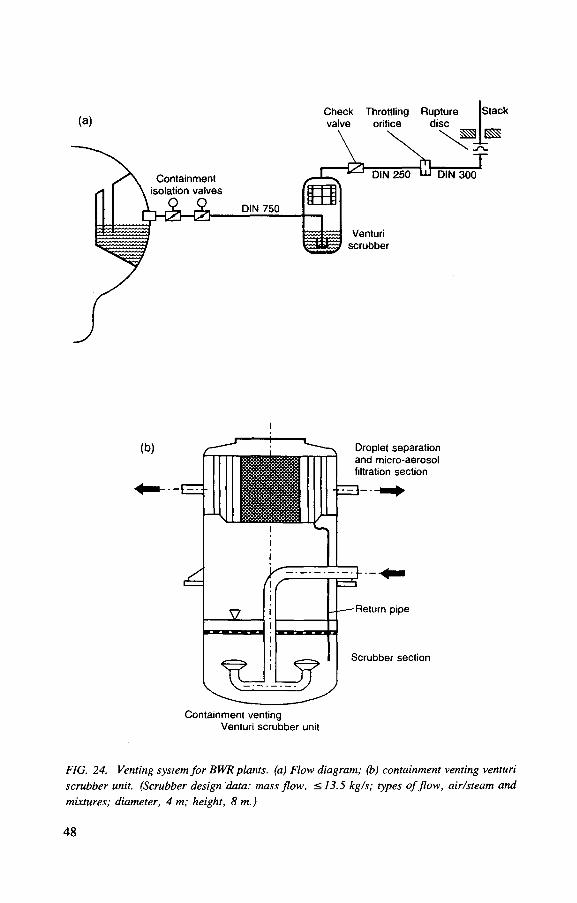
(b) Droplet separation and micro-aerosol filtration section
Return pipe
Scrubber section
Containment venting Venturi scrubber unit
FIG. 24. Venting system for BWR plants, (a) Flow diagram; (b) containment venting venturi scrubber unit. (Scrubber design data: mass flow, < 13.5 kg/s; types of flow, air/steam and mixtures; diameter, 4 m; height, 8 m.)
48

Top view of four unit
plant
Cross-section A-A
- t x } - Valve
Dust filter
HEPA filter
Blower, fan
Containment penetration
\ / \ Steam generator
" y v v Line with spray nozzles
— 2 — Liquid level
FIG. 25. Functional diagram of the CANDU containment system (1: reactor buildings (con-tainment); 2; vacuum building (containment); 3; pressure relief duct (containment); 4; blow-out and blow-in panels; 5; pressure relief valve; 6a; upper chamber; 6b; evacuation system; 7: vacuum building evacuation system; 8: vacuum building spray system; 9; dousing tank; 10; filtered air discharge system).
Inlets should be placed away from other ventilation exhausts and should be pro-tected by coarse wire screens or louvres. In areas of high rainfall, or when close to the sea, a moisture eliminator upstream from the filter may also be required and equipment may need corrosion protection. The quality of the air inlet filter used will be decided by the decontamination factor required. Inlets to highly active areas may use HEPA quality filters.
4 9

Vent stack
Heat sink
~777 Water pool
FIG. 26. Conceptual venting design from Italy (SBGT: stand-by gas treatment).
5.1.2. Once-through flow
In radioactive facilities the exhaust air is generally not recirculated in the plant for the recovery of heating or cooling capacity. For safety reasons, the air is released after passing through the plant even if effective exhaust air cleaning is provided.
It may be possible in some cases to use local closed loop cooling circuits for motors where the load that would be placed on a once-through ventilation plant is unacceptable. The local circuit should use HEPA filtration to prevent contamination of heat exchange surfaces. Closed loop cooling is also used in some reactor areas (CANDU).
5.1.3. The zone principle
The degree of release of radioactive materials into ventilation air will depend on the activities carried out in any area. Areas are generally divided into four zones,
50
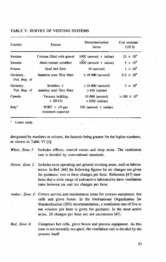
TABLE V. SURVEY OF VENTING SYSTEMS
Country System Decontamination factor
Cost estimate (US $)
Sweden Column filled with gravel 1000 (aerosol + iodine) 25 X 106
Sweden Multi-venturi scrubber y
1000 (aerosol + iodine) 5 X 10⁶
France Sand bed filter 10 (aerosol) 1 X 10⁶
Germany, Stainless steel fibre filter > 10 000 (aerosol) 0.5 X 10⁶
Fed. Rep. of
Germany, Scrubber + > 10 000 (aerosol) 3 X 10⁶
Fed. Rep. of stainless steel fibre filter > 100 (iodine)
Canada Vacuum building 10 000 (aerosol) >100 X 106
+ EFAD >1000 (iodine)
Italy" SGBT + off-gas 100 (aerosol + iodine) treatment expected
Under study.
designated by numbers or colours, the hazards being greater for the higher numbers, as shown in Table VI [2]:
White, Zone 1: Includes offices, control rooms and shop areas. The ventilation rate is decided by conventional standards.
Green, Zone 2: Includes most operating and general working areas, such as labora-tories. In Ref. [46] the following figures for air changes are given for guidance: two to three changes per hour. Reference [47] men-tions that a wide range of radioactive laboratories have ventilation rates between six and ten changes per hour.
Amber, Zone 3: Covers service and maintenance areas for process equipment, hot cells and glove boxes. In the International Organization for Standardization (ISO) recommendation, a ventilation rate of five to ten volumes per hour is given for guidance. In the most active areas, 20 changes per hour are not uncommon [47].
Red, Zone 4: Comprises hot cells, glove boxes and process equipment. As this zone is not normally occupied, the ventilation rate is decided by the process itself.
51
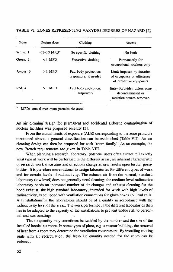
TABLE VI. ZONES REPRESENTING VARYING DEGREES OF HAZARD [2]
Zone Design dose
White, 1 <3-10 MPDa
Green, 2 < 1 MPD
Amber, 3 > 1 MPD
Red, 4 > 1 MPD
Clothing
No specific clothing
Protective clothing
Full body protection; respirators, if needed
Full body protection; respirators
Access
No limit
Permanently for occupational workers only
Limit imposed by duration of occupancy or efficiency
of protective equipment
Entry forbidden unless zone decontaminated or
radiation source removed
a MPD: annual maximum permissible dose.
An air cleaning design for permanent and accidental airborne contamination of nuclear facilities was proposed recently [3],
From the annual limits of exposure (ALE) corresponding to the zone principle mentioned above, a general classification can be established (Table VII). An air cleaning design can then be proposed for each 'room family'. As an example, the new French requirements are given in Table VIII.
When planning a research laboratory, potential users often cannot tell exactly what type of work will be performed in the different areas, an inherent characteristic of research work since aims and directions change as new results open further possi-bilities. It is therefore more rational to design laboratories for different types of work and for certain levels of radioactivity. The exhaust air from the normal, standard laboratory (low level) does not generally need cleaning; the medium level radioactive laboratory needs an increased number of air changes and exhaust cleaning for the hood exhaust; the high standard laboratory, intended for work with high levels of radioactivity, is equipped with ventilation connections for glove boxes and lead cells. All installations in the laboratories should be of a quality in accordance with the radioactivity level of the areas. The work performed in the different laboratories then has to be adapted to the capacity of the installations to prevent undue risk to person-nel and surroundings.
The air quantity may sometimes be decided by the number and the size of the installed hoods in a room. In some types of plant, e.g. a reactor building, the removal of heat from a room may determine the ventilation requirement. By installing cooling units with air recirculation, the fresh air quantity needed for the room can be reduced.
52

TABLE VII. ANNUAL LIMITS OF EXPOSURE
Room family Permanent admissible Maximum accident contamination (ALE)a contamination (ALE)a
I 0 0
II A <1 <80
II B <1 <4000
III A <80 < 4000
III B <4000 > 4000
IV >4000 > 4000
ALE: annual limit of exposure.
In high rooms, the air quantity required can be based on the first three metres of the height of the room in order to conserve air requirements. The air changes needed in radioactive areas for reasons of comfort are, as a rule, less than needed for other reasons.
5.1.4. Flow distribution
The design of the ventilation plant should ensure that if air is exchanged between different zones, then the flow must be from a lower zone number to a higher zone number. Within a given zone, some air may be supplied from a zone of lower rating and some directly from outside. This is usually the case with laboratories con-nected by corridors. Part of the air has to be supplied directly to the laboratory and part of the air passes from the corridor which warrants a defined airflow direction and stabilizes the pressure difference between the corridor and laboratory. To main-tain a higher pressure difference, of the order of 5 mm w.g., double doors or air locks are needed. It must be borne in mind that the directional airflow required is achieved by maintaining lower air pressure in the more contaminated areas towards which the air is intended to flow. The drop of pressure in each zone may be several mm w.g. for Zone 2, 50-100 Pa (5-10 mm w.g.) for Zone 3, and 150-450 Pa (15-45 mm w.g.) for Zone 4 [46],
The large volume of ventilation air often needed in radioactive facilities implies that in many instances some form of inlet flow distribution will be required for per-sonal comfort and to ensure reliable operation of equipment, such as electronic com-ponents and motors, etc.
53

TABLE VIII. FRENCH CLASSIFICATION BY 'ROOM FAMILY'
Contaminat ion risks
Organizat ion of ventilation according to contamination risks
Recyclint
Examples
Extraction or transfer from Zone 1, FI
Family I CP = 0 CA = 0
Extraction or transfer from Zones 1 or 2, FI
Extraction or transfer from Zones 1, 2, 3 or 4, FI
Zone 1
X Zone 2
X Zone 3
Central filtration
plant Zone: 1
Control r o o m
© Corr idors, s torage area . . .
© Extraction or transfer from Zones 1 or 2, FI Zone 2
L.
THE(S,)
© Family H A C P £ 1 CA = improbable
< 80 MPC
Extraction or transfer from Zones 2 or 3, F I I A HE(S2)
Transfer from Zones 1 ,2 or 3, FI
Zone 3 THE(S,)
© Extraction or transfer from Zones 2, 3 or 4, FIIA -
Transfer from Zones 1, 2, 3 or 4, FI
Zone: 2, 3, 4
Corr idors Intervention areas Laborator ies Reagent r o o m
Zone 4 £ =
THE(S,)
© Extraction or transfer from Zone 3, FIIB
Constant monitoring
6nkP THE(S,
Family I1B CP < 1 C A < 4000 MPC
Zone 3 •HJ- THE(S2)
Extraction or transfer from Zones 3 or 4, FIIB
I i
Constant monitoring
©
HE,
Transfer from Zones 2, 3 or 4, FIIA
3_ Zone 4
THE(S2)
H—SJ-THE(S,)
©
Zone; 3, 4
Fission product evaporators
Cold chemica l cells Water process ing Resin s torage Solvent process ing Solvents
Fission product s torage
Filtration sector Estimation of filtration according to contaminat ion thresholds
General funct ion building venti lat ion
54

TABLE VIII. (cont.)
Contaminat ion risks
Organizat ion of ventilation according to contaminat ion risks Examples
Family H3A C P < 80 MPC CA < 4000 MPC
Extraction or transfer from Zone 3, FIIB, or Zone 3, FIIIB
HE(Sa) Transfer from Zones 2 or 3, FIIA
Extraction or transfer from Zones 3 or 4, FIIB or Zones 3 or 4, ^
FIIIA HE H i
Transfer from Zones 2, 3 or 4, FIIA
Sampling opti<
THE(S , )
Family I H B CP < 4000 MPC CA = Major over
4000 MPC
Family I V CP: around
4000 MPC 1 CA: greatly in
eixcess of 4000 MPC
Extraction or transfer from Zones 2 or 3, FIIA or FIIB, or Zone—1
3, F I I I A Hvfr T H E I S 2 ) j
Extraction or transfer | from Zones 2 or 3, f ] l . FIIIA or FIIB
THE(S 2 ) I
i
Zone: 3, 4
Low contaminat ion risk intervention cel ls
I Sampling optioni
Extraction or transfer from Zone 3, FIIIA or FIIB
Specific processing Procedure i i :THE(S 2 ) ; THE<S,)
Zone: 4
Cutting cell
High contaminat ion risk intervention cell
Zone: 4
Pu powder area
^ ^ In situ sampl ing
p de tec t ion
( y f y monitoring
g High efficiency filter
y Very high efficiency filter
CP: Cons tan t contaminat ion
CA: Accidental contamination
S,: S y s t e m s ensur ing c o n s t a n t air extraction a n d filtration
S2: S y s t e m s ensur ing c o n s t a n t air extraction while filters a r e being r e p l a c e d
F: Family
Filtration sector Estimation of filtration according to contaminat ion thresholds
General funct ion building venti lat ion
55
5.1.5. Efficient use of ventilation air
The ventilation system design should minimize the quantity of air needed, as the cost of the ventilating and filtering plant will be proportional to the air volume handled. First of all, the process, as a whole, should be surveyed. The material involved can sometimes be replaced by a less harmful one, or the quantity reduced by applying another research method. In a production plant, the type and amount of material cannot be changed, but the spread of dust could be reduced by changing the process, for example by turning from dry to wet handling.
Many types of enclosures (hoods, glove boxes and cells) are available which will prevent hazardous products from being spread into the room air and reduce the air volume contaminated with radioactive dust. By segregating the exhaust system into different lines, the degree of cleaning can be adapted to the quality of the air in every line. In work rooms where there is no need for respirators or breathing apparatus, the air does not normally have to be filtered before release into the atmosphere. The exhaust must be filtered, however, from a work room with a high dust concentration. The determining factor may be the potential risk of the spread of activity in abnormal or emergency conditions. Special dust enclosures are supplied with local prefilters to reduce the dust concentration to a level suitable for high effi-ciency filters. These will also reduce dust deposition in ducting and thereby remove a possible source of radiation exposure or fire, especially if highly active or pyrophoric materials are being handled.
Booster fans can be installed in the lines from various enclosures that require high pressure differentials. Segregation makes it possible to design the ducts and filters that lead from special enclosures in corrosion resistant material to the point where the air is diluted in a large volume of air to make the concentration of corro-sive impurities harmless.
The total air quantity will also depend on the extent to which the air can pass several areas in series. Office ventilation air can pass the corridor or be used for supplying air to the laboratory, where the amount of air needed may be determined by the number of fume cupboards installed.
In laboratories, localized containment can be of two kinds: an essentially total enclosure, for example a glove box, or a semi-enclosure, such as a fume hood or cupboard. Since air quantities are reduced in proportion to the reduction in open area through which the air flows, a more economical use of air is achieved if the source is enclosed.
5.1.6. Exhaust air centralized systems
Plant layout generally influences the degree to which the exhaust air system should be centralized. Complete segregation of active and non-active exhaust sys-tems should be considered.
56
Either individual rooms, hoods or buildings have an exhaust fan and a stack, or large paired fans are installed at a central location and the rooms, hoods or build-ings are connected to these fans through large exhaust ducts. Both systems have advantages and disadvantages.
The advantages of individual exhaust are: (1) easier design and system balanc-ing; (2) better design and construction schedules owing to ready availability of small fans; (3) reduced costs resulting from: (a) smaller ductwork, (b) lower friction losses.
The disadvantages of individual exhaust are: (1) less overall system reliability because of difficulty in providing stand-by exhaust equipment; (2) higher costs resulting from: (a) larger space requirements needed to house fans, (b) extensive installation costs for power feeds, motors, starters, etc., (c) number of discharge stacks required, (d) inspection and maintenance of many small units, (e) need for many exhaust monitoring systems.
For a high level radioactive plant, the arguments are in favour of centraliza-tion. When high reliability is needed, a centralized system is more suitable, and a high stack and an advanced monitoring system, necessary for advanced radioactive plants, also favour a centralized system. In a big plant, a combination of the two sys-tems is the best solution. For non-radioactive and low activity areas, individual exhaust systems can be used, but for areas with high contamination levels, a central-ized system should be installed. The pressure balance between the different zones is easier to maintain in a centralized system because a constant pressure can be kept in the main exhaust duct. The air balance is not jeopardized by disturbances of individual fans or clogging of individual filters.
When a reduction in operating costs is to be achieved by reducing airflow during non-working hours, a centralized system is more convenient, since reduced airflow can be obtained by speed regulation, or by varying the number of fans in operation.
5.1.7. Accident conditions
The abnormal conditions or accident conditions for which the system has to be designed may be so different from normal conditions that a special emergency sys-tem has to be installed. Such conditions normally arise only in nuclear power plants. The cleaning requirements and physical conditions, such as temperature and humid-ity, may call for a separate system to take over the ventilation in the event of an emergency (see Section 4.3.2).
The system must be designed to prevent the spread of fire. In a building where high level radioactive materials are handled, non-combustible materials should, where possible, always be used. If the whole ventilation plant is shut down in the event of fire, the fire will not be choked by lack of oxygen, but the smoke may make fighting the fire difficult and the spread of radioactivity will cause more trouble than
57

the fire itself. The exhaust system can therefore be kept working and only the supply system shut off, at least as long as the fire is not catastrophic. If hydrogen or other explosive gases are involved, it may be necessary to maintain the supply system to minimize the risk of explosion. If fire is seen as a hazard, the final filters should be of a type that has the best fire resistance and high temperature performance available.
In laboratories, glove boxes for processes using inflammable materials may ppse problems that can only be solved by the use of dampers in the inlet ducting and the use of inert atmosphere quenching (N2). Quenching may also be used in larger facilities. Final ventilation filters may become blocked by deposited smoke before they deteriorate significantly as a result of high temperature effects. Heat resistant primary and secondary filters should still be used under these circumstances as they will be a barrier to dust release so long as they remain intact.
Spark arrestors should be used under process conditions where sparks and/or inflammable material can be carried into the ducting. If the process exhaust point has no prefilter, the spark arrestor should be placed at the exhaust point. In this case, however, it may be necessary to replace or clean the spark arrestor at regular inter-vals as it may become blocked with deposited dust. If a prefilter has been installed, the spark arrestor should be positioned immediately downstream from the prefilter. Enough ducting should be installed between the spark arrestor and downstream ven-tilation filters to give a transit time of at least 5 s at the design flow rate.
5.1.8. Final filtration
All exhaust ventilation air from a nuclear facility must be filtered if, under either normal or accident conditions, it can be shown that without filtration an unacceptable radiation hazard would result. Local prefilters are usually discounted in this context as they are assumed to fail under accident conditions. The number of final HEPA filter stages in series that are required can be obtained directly from the expected plant effluent aerosol concentration/activity and the envisaged stack discharge aerosol concentration. Operating experience and data from similar plants can be a useful guide. In any event, in processing plants and laboratories where high temperature or high aerosol concentration accident conditions can exist, there should always be at least two stages of final HEPA filtration in series. A typical ventilation scheme incorporating the features described above is given in Fig. 27.
5.2. LABORATORIES, CELLS AND REACTOR BUILDINGS
5.2.1. Laboratories
Of the many types of laboratories for radioactive work, some are planned only for special work, while others are intended for general applications. For special types
58
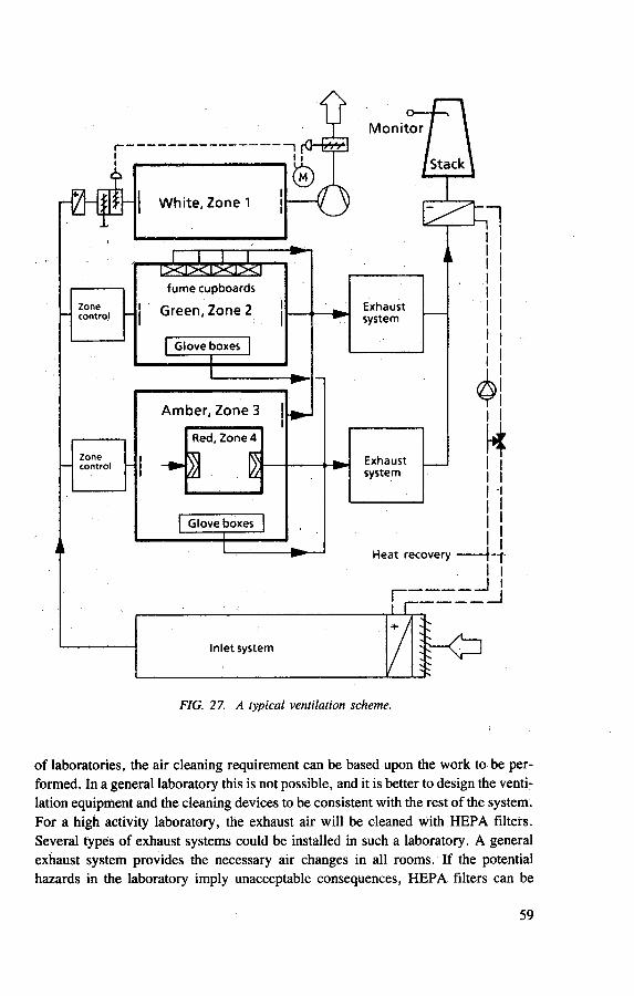
of laboratories, the air cleaning requirement can be based upon the work to be per-formed. In a general laboratory this is not possible, and it is better to design the venti-lation equipment and the cleaning devices to be consistent with the rest of the system. For a high activity laboratory, the exhaust air will be cleaned with HEPA filters. Several types of exhaust systems could be installed in such a laboratory. A general exhaust system provides the necessary air changes in all rooms. If the potential hazards in the laboratory imply unacceptable consequences, HEPA filters can be
59

installed. Special equipment is often required to contain the radioactive work performed in the laboratory. Such equipment includes fume cupboards, hoods, glove boxes, lead cells, etc.
5.2.1.1. Fume cupboards
Fume cupboards for work with trace levels of radioactivity could be connected to a filtered general exhaust system. When dust generating work is performed in a cupboard, pre-cleaning of the exhaust air is required. A central bank of HEPA filters can serve many fume cupboards. Every fume cupboard is provided with local prefilters which can be built into the cupboard or placed in a separate filter housing. If they are mounted in the cupboard, changing the filter is difficult because bulky laboratory apparatus reduces the accessibility of the filter.
A separate housing (see Fig. 28) is a more flexible design that allows a hlter to be installed in any type of fume cupboard, provided that enough space is available. The filters can be changed without disturbing the work in the cupboard.
5.2.1.2. Open boxes
To reduce the air volumes needed to maintain a high velocity through the access area in a fume cupboard, different kinds of boxes with small openings can be used. This is especially useful for routine operations, when the equipment used can be more or less permanently installed in the box, for example in a production line for isotopes or fuel pellets. The openings should be large enough to permit easy access to the box (15-20 cm in diameter) and an air velocity of 0.5-1 m/s should be maintained through them, this airflow generally providing enough air changes in the box. Sometimes the openings are covered with rubber strips for a further reduc-tion in the airflow, but this is not necessary and may lead to a spread of radioactivity as the strips become easily contaminated. The filter requirements are the same as those for fume cupboards, but the comparatively small quantity of air reduces the size and number of filters needed.
5.2.1.3. Glove boxes
• When material of high radiotoxicity, such as plutonium, is being handled, com-plete containment of the working space is desirable. To ensure that any leakage will be from outside into the box, the box is kept at a slight negative pressure of 200-500 Pa (20-50 mm w.g.), depending upon the contamination risk of the work in the box. As the sensitivity when working with gloves is influenced by a negative pressure over 250 Pa (25 mm w.g.), the pressure differential is reduced when safety considerations permit. The appreciable volume of the gloves must be taken into
60

Operat ing area
Liquid waste container
To extract duct ing
Prefilter j HEPA f i l ter
M 900
Li
1200 mm
1500 mm
1800 mm
FIG. 28. Fume cupboard with a HEPA filter.
account, however, since rapid movement with them easily causes overpressure in the box if a negative pressure of 200-300 Pa (20-30 mm w.g.) is not maintained.
5.2.1.4. Single pass ventilation systems
Ventilation airflow requirements can vary within wide limits, but, for less hazardous work in a glove box, ten changes per hour will suffice. In designing the exhaust system, however, safety in the event of a major break, such as a glove failure, must be considered. The usual glove failure is only a minor tear, but in the basic design a reasonable velocity over the glove port is assumed. For a diameter of 15 cm (6 in) and a velocity of 0.5-1 m/s, the required airflow is 40-80 m3/h. In some cases, the normal glove box flow rate, to give the required number of air
61

cz£> Purge f l ow f rom glove box
Flow to extract duct
FIG. 29. Vortex amplifier (normal position).
changes, will not be sufficient to provide the velocity required through an open port when a glove has failed. Vortex amplifier systems have been developed that switch to a high flow rate when the box pressure drop reduces owing to a glove failure (Figs 29 and 30) [7], As the work performed in glove boxes is always hazardous, the exhaust filtration must be efficient. Glove box filters with a penetration of less than 10"4 are available.
Wet chemical processes release vapours which may condense and cause mist-ing of the panels. Condensation on the panels will be a function of the following:
(a) Nature of substance being evaporated and its surface area, (b) Amount of evaporation, (c) Temperature of the liquid and the movement of gas over it, (d) Temperature of air inside and outside the enclosure, (e) Temperature of the clean side of the panel.
A flow of 10-15 changes per hour may be required to prevent condensation, and con-, sideration should be given to the use of condensers to remove the vapours.
Corrosive vapours and gases must not be released into the box atmosphere, but should be vented from the process equipment by a separate system using scrubbers, or other appropriate means of removing and/or neutralizing them. However, the
62

Flow to extract duct
-2.5 kPa
Control filter
Purge filter
Purge control valve
FIG. 30. Vortex amplifier (switch position).
escape into the box atmosphere of some such vapours or gases may be unavoidable and flow rates of 30 changes per hour or more may be required in extreme cases to prevent excessive concentrations in the box and in the extract system.
For dry handling of plutonium an overall penetration of less than 10~6 is required. Filters should preferably be of a non-combustible type, but the level of cor-rosion resistance necessary should also be considered. Commercial filters are avail-able which are small enough to be passed in and out through a regular transfer port. Even if the required efficiency can be obtained with the glove box filter, a backup filter should be installed in the exhaust system, such a filter being capable of serving many glove boxes.
Air for the ventilation of the box is taken from the room and passed into the box through a filtered inlet. The inlet filter should have such dimensions that the pressure drop of the dirty filter can be overcome by the pressure difference between the room and the interior of the box. The inlet filter prolongs the. life of the exhaust filter and prevents the spread of contamination in the event of the glove box becom-ing accidently pressurized. Normally, HEPA quality filters are used, especially if pressurization is a possibility. The inlet and outlet connections to the box can be
63

closed, and as the box itself is very tight it can be disconnected and moved to a ser-vice area. The maximum acceptable leak rate is usually less than 0.5% of the box volume per hour at a pressure difference of 1000 Pa (100 mm w.g.).
5.2.1.5. Recirculating systems
In such systems the gas is recirculated through a gas purifying and re-circulating plant that must be designed to remove corrosive, explosive and other undesirable gases and vapours from the box atmosphere and to control the pressure in the system. These systems are suitable for processes with dry air or inert gas atmospheres.
The boxes must be very tight. The specified maximum leak rate is usually 0.05% of the box volume per hour at a negative pressure of 1000 Pa (100 mm w.g.). The box might be connected to an exhaust system to be used in case of emergency. The same requirements may be specified as for the single pass system, i.e. that it should prevent the spread of contamination in the event of a glove failure.
5.2.2. Cells
When large quantities of gamma emitting material are handled, shielding must be provided. If operations are likely to spread dust, there is a contamination risk and the general requirements for hot cell ventilation and filtering are, in principle, the same as those for glove boxes. Small cells are often shielded with lead blocks, but large cells are built up with thick concrete walls. The high activity level and the size of the cells necessitate requirements in addition to those specified for glove boxes.
A controlled single pass system is usually used for hot cells. Air from the main-tenance zone is supplied to the cell via an inlet filter, at a controlled flow rate which depends on the work carried out in the cell. The permanent character of a concrete cell building makes it necessary to design the ventilation system for any kind of work that can possibly be performed in the cell. The hot cells are often designed for a ven-tilation rate of 60 changes per hour. If possible, the supply and exhaust ports should be located so that air flows from the top of the cell to the bottom. The airflow thereby contributes to the settling of dust particles in the cell. When opening the shielded plug door to the cell, a velocity of 1 m/s through the opening is desirable to avoid the spread of radioactive dust into the maintenance area. The airflow for this purpose will probably be the controlling factor for the size of the exhaust filter. A primary HEPA filter, or a prefilter of non-combustible type, should be placed in the exhaust line. These filters can be mounted inside the cell, but there will be a risk of accidental damage and filter handling may be a problem if manipulators have to be used. The push-through circular filter concept (Section 5.3.1.4) should be considered as an alternative. Final HEPA filters are required to reduce the dust concentration of the exhaust air and as a mandatory safety measure. As the large cells are often used for
64

handling irradiated fuel elements, some impregnated charcoal beds may be needed to remove the fission product iodine, which may cause health hazards if released into the surroundings.
5.2.3. Reactor buildings
The main function of the reactor containment ventilation system is to maintain the area under subatmospheric pressure. The cleaning requirements for air and gases leaving a reactor plant differ according to the system concerned. There are ventila-tion systems for different areas of the reactor buildings which usually are divided into zones of varying accessibility: unrestricted admission, restricted admission and no admission. An off-gas system is provided to collect gases, steam and vapours from the process systems.
For the general ventilation of areas which are accessible during operation, the contamination level must be kept low. Since people are present in these areas during working hours, the concentration of radioactive contamination must be kept well below the maximum derived air concentrations.
Facilities which accommodate the primary coolant systems may have a high concentration of activity in the air from leakage of the coolant medium, which may contain activated corrosion products, as well as fission products from punctured fuel elements. A high activity concentration in the air would not influence the operation as the areas are not accessible because of the high radiation level for the primary coolant. The release of fission products from fuel elements that have cracks or pin-holes in the cladding depends very much on the operating temperature of the fuel. At temperatures above 1600°C, the release of iodine is accelerated. The cleaning device for the exhaust air should have a high level of efficiency and should consist of a particulate filter followed by an iodine filter, such as an impregnated charcoal bed.
All reactors have some kind of off-gas system to collect gases from the reactor system for treatment before release through the stack. Apart from aerosols, the off-gas may contain noble gases and iodine. As iodine is often the most harmful of the fission products that may leak from the fuel, an iodine adsorption filter is needed in addition to HEPA filters. The noble gases are only delayed a short while in a char-coal bed at normal temperature, and to obtain an appreciable delay the bed could be cooled to a low temperature. A delay tank or chromatographic facility is often used to obtain thedesired decay. Since the decay products will form radioactive aerosols, the decay system should be followed by a HEPA filter.
Emergency ventilation systems are used to vent the containment following an accident. Designs vary with the type of reactor (see Figs 21-24). Circulation systems can be placed inside the containment for cooling and cleaning purposes. Temperature
65
conditions must be considered and, for water cooled reactors, the humidity of the air is high. Since iodine is the most hazardous fission product, the cleaning device may consist of a particulate filter and an iodine adsorber. To prevent the particulate filter from becoming wet from air mixed with water droplets, and to maintain the efficiency of the charcoal bed at high humidity, a moisture separator and, if possible, heating coils should be placed upstream from the filters. The noble gases are not reduced by the use of such cleaning arrangements, but, since they are contained, the small amount that leaks out can be released through the stack or, when the require-ments are more stringent, the leakage can be pumped back into the containment. For small research reactors, the fission product inventory is moderate and the reactor building can be vented by an emergency ventilation system, as described above, which is connected to a stack.
5.3. FILTER HOUSINGS
Housings can be conveniently divided into two categories:
— Low to high contamination, low radiation; where shielding is not required; — Low to high contamination, high radiation; where shielding is required.
5.3.1. Unshielded housings
Unshielded installations are typically used for building ventilation and space extract. The total volume flow will decide what form of housing is to be used. Smaller installations should use standard 500-950 L/s HEPA filters in individual metal housings (variously known as canister, caisson or bag change housings). Larger installations should use the shelf or ladder systems, where the required num-ber of filter inserts is mounted within a single housing.
5.3.1.1. Canister housings
Standard 500 or 850 L/s rectangular filter inserts, or 500 or 950 L/s circular filter inserts, can be combined within individual canister housings (in series, in parallel, or both) to provide the required filter installation. This technique is usually restricted to a maximum of ten housings in parallel. A typical parallel bank is shown in Fig. 31. Each housing can be isolated for change out. If the system has four or more filters in series, the additional flow imposed on the remaining units when one filter is isolated can normally be accommodated. If fewer filters are used, then an
66
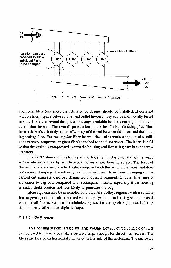
FIG. 31. Parallel battery of canister housings.
additional filter (one more than dictated by design) should be installed. If designed with sufficient space between inlet and outlet headers, they can be individually tested in situ. There are several designs of housings available for both rectangular and cir-cular filter inserts. The overall penetration of the installation (housing plus filter insert) depends critically on the efficiency of the seal between the insert and the hous-ing sealing face. For rectangular filter inserts, the seal is made using a gasket (sili-cone rubber, neoprene, or glass fibre) attached to the filter insert. The insert is held so that the gasket is compressed against the housing seal face using cam bars or screw actuators.
Figure 32 shows a circular insert and housing. In this case, the seal is made with a silicone rubber lip seal between the insert and housing spigot. The form of the seal has shown very low leak rates compared with the rectangular insert and does not require clamping. For either type of housing/insert, filter insert changing can be carried out using standard bag change techniques, if required. Circular filter inserts are easier to bag out, compared with rectangular inserts, especially if the housing is under slight suction and less likely to puncture the bag.
Housings can also be assembled on a movable trolley, together with a suitable fan, to give a portable, self-contained ventilation system. The housing should be used with a small filtered vent line to minimize bag suction during change out as isolating dampers may often have slight leakage.
5.3.1.2. Shelf system
This housing system is used for large volume flows. Poured concrete or steel can be used to make a box like structure, large enough for direct man access. The filters are located on horizontal shelves on either side of the enclosure. The enclosure
67

o\ 00 Contaminated air stream
Filter insert
Housing lid Tapered spigot feature of housing
FIG. 32. Plug-in circular insert filter housing.

constitutes the dirty side of the duct and, consequently, access is possible using pro-tective clothing, e.g. a pressurized suit, when rectangular filter inserts are used. Circular section filter inserts can be mounted, with latches so that the change out area is the clean side.
Sealing is achieved by a combination of differential pressure and the weight of the filter. Rectangular filter inserts will also require clamping. Shelf baseplates which form the housing seal face must be flat and free from steps if rectangular inserts are used. The sealing systems are illustrated in Fig. 33. Used filters are nor-mally removed in bags.
5.3.1. 3. Ladder system
This is similar to the shelf system, except that filter inserts are installed in a carefully fabricated frame which forms one wall of the concrete or steel enclosure, as shown in Fig. 34. A large number of filter inserts can be mounted in one housing. It is important that deep pleat rectangular filter inserts are mounted in this system, with the pleats in a vertical position to avoid sagging or slumping of the pleats. To achieve a good seal with a system using rectangular inserts, effective location and clamping devices are required. Circular inserts are self-locating and do not require clamping to maintain a good seal. As with the shelf system, filter insert changing requires the use of pressurized suits if rectangular inserts are used.
5.3.1.4. Glove box system
Rectangular glove box HEPA filters rated up to 25 L/s are normally clamped in the box extract line inside the glove box. Where regular filter changing may be required owing to high dust loads or with significant contamination, a push-through change system based on circular filter inserts up to 160 L/s flow capacity should be considered (see Fig. 35). They may be bagged out and are designed to allow posting out through standard size ports.
5.3.2. Shielded installations
The requirement for a shielded system is determined on the basis of a hazard analysis, taking into account the buildup of active deposits in filters, internal surfaces of ducts, etc. Where there is a risk of fire, a filter housing should be located as far from the source as is practicable.
Before proceeding with the design of a shielded housing installation, the following factors should be considered, in addition to those covered previously:
— In laboratories the layout of the cells containing the process plant may lend itself to a centralized common sytem, or several smaller systems. The total
69
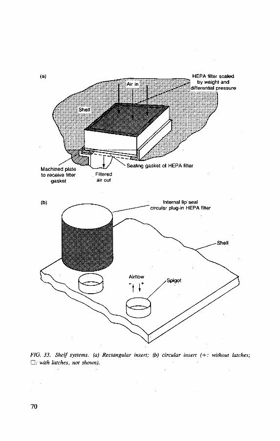
gasket air out
FIG. 33. Shelf systems, (a) Rectangular insert; (b) circular insert f+: without latches; • : with latches, not shown).
70

Location Clamping
(b)
Wall
Airflow from the dirty side into the
filter and out radially
Clean side
Circular filter sealing spigot
Rails to support circular filters, latch on end to retain filter
FIG. 34. Ladder systems, (a) Rectangular insert; (b) circular insert.
length of contaminated ductwork, the number of fans required and plate-out of activity within ducts will have an important influence on the choice of system;
— Waste handling and disposal philosophy with regard to disposal routes for HEPA filters with relatively high activity loadings.
71
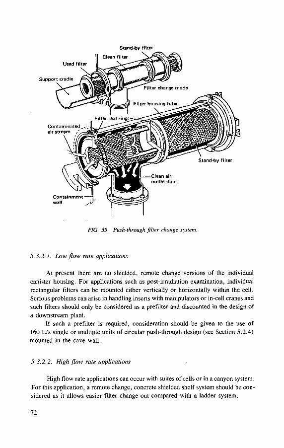
Stand-by filter
FIG. 35. Push-through filter change system.
5.3.2.1. Low flow rate applications
At present there are no shielded, remote change versions of the individual canister housing. For applications such as post-irradiation examination, individual rectangular filters can be mounted either vertically or horizontally within the cell. Serious problems can arise in handling inserts with manipulators or in-cell cranes and such filters should only be considered as a prefilter and discounted in the design of a downstream plant.
If such a prefilter is required, consideration should be given to the use of 160 L/s single or multiple units of circular push-through design (see Section 5.2.4) mounted in the cave wall.
5.3.2.2. High flow rate applications
High flow rate applications can occur with suites of cells or in a canyon system. For this application, a remote change, concrete shielded shelf system should be con-sidered as it allows easier filter change out compared with a ladder system.
7 2
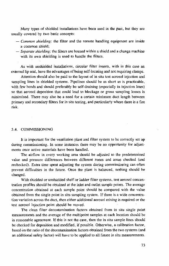
Many types of shielded installations have been used in the past, but they are usually covered by two basic concepts:
— Common shielding: the filter and the remote handling equipment are inside a common shield;
— Separate shielding: the filters are housed within a shield and a change machine with its own shielding is used to handle the filters.
As with unshielded installations, circular filter inserts, with in this case an external lip seal, have the advantages of being self-locating and not requiring clamps.
Attention should also be paid to the layout of in situ test aerosol injection and sampling lines in shielded systems. Pipelines should be as short as is practicable, with few bends and should preferably be self-draining (especially in injection lines) so that aerosol deposition that could lead to blockage or gross sampling losses is minimized. There may also be a need for a certain minimum duct length between primary and secondary filters for in situ testing, and particularly where there is a fire risk.
5.4. COMMISSIONING
It is important for the ventilation plant and filter system to be correctly set up during commissioning. In some instances there may be no opportunity for adjust-ments once active materials have been handled.
The airflow in every working area should be adjusted to the predetermined value and pressure differences between different zones and areas checked (and rechecked). Extra time spent adjusting the system during commissioning can often prevent difficulties in the future. Once the plant is balanced, nothing should be changed.
With shielded or unshielded shelf or ladder filter systems, test aerosol concen-tration profiles should be obtained at the inlet and outlet sample points. The average concentration obtained at each sample point should be compared with the value obtained from the single point in situ sampling system. If there is a wide concentra-tion variation across the duct, then either additional aerosol mixing is required or the test aerosol injection point should be moved.
The clean filter decontamination factors obtained from in situ single point measurements and the average of the multipoint samples at each location should be in reasonable agreement. If this is not the case, then the in situ sample lines should be checked for deposition and modified, if possible. Otherwise, a calibration factor, based on the ratio of the decontamination factors obtained from the two systems (and an additional safety factor) will have to be applied to all future in situ measurements.
7 3

6. HANDLING, INSPECTION AND INSTALLATION OF NEW FILTER INSERTS
6.1. ACCEPTANCE OF FILTER INSERT SHIPMENT AND QUALITY ASSURANCE
HEPA filter inserts are packaged individually by the manufacturer in sturdy corrugated cardboard cartons, with extra shock absorbing material in the corners. The individual responsible for accepting HEPA filters at the destination should inspect the shipment during unloading to verify that the shipping cartons are undamaged, that the filters have been stacked not more than three high and that they are in the orientation indicated by the arrows and directions affixed to the outside of each filter carton (AG-I, American Society of Mechanical Engineers, Arti-cle 7000). Damaged cartons and/or errors in orientation during shipment are reasons for refusing to accept the filters or, at the very least, agreeing to tentative acceptance, with final approval dependent on the filters passing a searching inspection after com-plete removal from their shipping cartons.
Prefilters and mist eliminators are also subject to shipping damage and the con-dition of the shipping containers should be examined carefully before they are accepted at the time of delivery. However, these items are less fragile and less sub-ject to damage during shipment. Further, the collection efficiency expected from these items is not so great that minor damage to holding frames and exposed surfaces of the filter surface will significantly degrade performance. Therefore, standards for unacceptable shipping damage should not be as rigid as for HEPA filters, but damage that affects performance adversely, such as visible holes through the filter medium, racking of the holding frames beyond allowable limits, or damage to the seal between the medium and holding frame, should be considered as being an adequate reason for rejection of the shipment.
6.2. FILTER INSERT STORAGE
Unused filters should be stored in a clean, dry enclosure in their original ship-ping cartons, carefully observing the manufacturer's directions regarding orientation and the limit on the height of the stacks. The rule with regard to orientation is that deep pleat filter inserts should be stored with their pleats in the vertical position in order to avoid sagging of the filter pack, whereas minipleat filter inserts should be stacked with pleats horizontal for the same reason. If filter inserts have been shipped strapped to pallets, and there is no obvious need to break the package apart to inspect for shipping damage, then they should be stored in that condition until used. If inserts have been removed from their shipping cartons for acceptance inspection or retest-
74

ing, they should be returned very carefully to their undamaged shipping cartons, making certain that the direction of the filter pleats and the orientation directions on the outside of the carton have been co-ordinated.
Filter insert storage areas must be inside a building and should be warm and dry. The storage area should be positioned so that leakage from steam pipes, flooding from local drains or similar faults in services cannot affect stored inserts. Inserts should be stored on pallets to raise them off the floor to avoid excessive dust, damp-ness from floor washing or damage caused by blows from brooms or cleaning machines. Because of the need to avoid damage, it may be necessary to keep filter insert store areas separate from other stores.
The inserts should be used in the sequence in which they are received from the manufacturer, so that no insert remains stored for an excessive period. The storage of a number of inserts and cartons gives rise to a fire loading which presents a genuine hazard. Consideration should be given to the location of the store with respect to other sources of fire and fire loadings. Any insert suspected of being damaged should not be used. It may be cleared for use if retested successfully and if it is free from visible defects.
6.2.1. Withdrawing filters from storage for use
As a general rule, clean filter inserts should be transferred in their original shipping cartons from storage to the area where they will be installed in order to avoid damage during transportation. The manufacturer's directions regarding orien-tation and stacking height should continue to be observed. Filter inserts should be unloaded in a clean area that is large enough to permit their safe removal and thorough inspection before they are brought to the housing for installation. Space must also be available in the unpacking area for convenient reception of spent inserts prior to their removal to waste storage.
6.3. PRE-INSTALLATION UNPACKING AND INSPECTION
6.3.1. Filter unpacking
When handling an insert in its carton, the box should be tilted on one corner, picked up and carried while supporting it at diagonally opposing corners [48], To avoid damage to the delicate filter medium of a HEPA insert, removal from the ship-ping carton should be accomplished by opening and folding back the top flaps of the carton and taping them open if necessary. Next, the carton should be inverted and the open side placed on a clean, smooth surface, such as a table top. Finally, the inverted carton should be lifted carefully off the insert. The insert unit must be
7 5
grasped only on the outer frame surfaces and contact should be avoided with the filter pack enclosed within the frame.
6.3.2. Inspection prior to installation
Filter inserts should be inspected carefully as a last procedure before installa-tion to make certain that defective units that could have been detected by visual examination are not placed in mounting frames. Although defective HEPA inserts will be discovered during in situ testing, it is often difficult and always time consum-ing to search for one defective insert in a large bank of identical units, remove it when found, replace it with a new unit, and then retest the entire filter bank. Inspec-tion of the entire paper surface with the aid of a bright light held on the opposite side of the insert wiil reveal all defects in the paper and the seal between filter frame and filter pack that will result in failure to pass the in situ filter test after installation. Other factors that require inspection prior to installation are adherence to dimen-sional tolerances, damage to filter frame, damage to corrugated separators of the HEPA inserts, mechanical strength and firmness of the filter pack and damage to gaskets. Pre-installation inspection can be even more important for prefilter inserts and mist eliminators, inasmuch as they may not be subjected to a final quantitative in situ test after installation and before they are placed in service.
6.4. INSTALLATION
Before installing the filter inserts, the mounting frames and clamping devices should be inspected carefully for flexure damage and the presence of dirt, paint, or weld metal on the sealing surfaces. It is also important to ascertain that all of the clamping mechanisms are in place and easily operated before filter installation begins in order to minimize the time personnel must work in potentially contaminated enclosures.
At least four, and possibly eight, pressure points are required for rectangular HEPA filter inserts and demisters. Individual clamping of each filter unit is preferred. Common bolting, in which holding clips (or bolts) bear on two or more adjacent filter inserts, has been widely used because it is less expensive than individual clamping and requires fewer loose items to be manipulated within the con-fines of the housing during a filter change. However, common bolting limits the abil-ity to adjust or replace individual filter inserts in the bank without disturbing the seals of adjacent units.
The nuts and bolts of the clamping system must be made of dissimilar materials to prevent galling and seizing. Bolting materials and clips must be resistant to corro-sion. Stainless steel (300 series or equivalent) bolts with brass nuts are frequently
7 6
used, but nuts made from a precipitation hardening (PPH) grade of stainless steel, treated at a value substantially harder than the bolt, may be.used in lieu of brass. Springs, if used, should also be made from a PPH grade of stainless steel if they are to resist corrosion and relaxation over a period of service.
6.5. HEALTH PHYSICS AND ERGONOMIC CONSIDERATIONS
Because monitoring, preventive maintenance and filter insert replacement will involve potential exposure to radioactive materials, special consideration must be given to providing adequate working space for personnel wearing protective clothing and respiratory equipment.
6.5.1. Size of Alter banks
Insofar as possible, filter banks should be laid out in an array of three filter inserts high. Where floor space is at a premium, the bank may be arranged with one three-high array above another if large capacity is required. In no case should filter insert changing be carried out using ladders or temporary scaffolding. To require a workman dressed in bulky protective clothing (with sight obscured by a respirator or gas mask and sense of feel dulled by double gloves) to manipulate a ladder or scaffold within the confines of a filter house is an open invitation to filter damage and personnel injury. Based on the 95th percentile man, the maximum height at which a man can operate hand tools effectively is 2 m, and the maximum load he can handle at a height of 1.5 m or more is 18 kg. Therefore, provision for access to the higher tiers of filter inserts via a service platform is necessary.
6.5.2. Layout of filter banks
The procedures that will be required for construction and operational main-tenance must be considered carefully. Adequate clearances for access must be main-tained at turning points and between the bank and the nearest obstruction. Passageways between banks, and between banks and the housing wall, must be wide enough for welders to operate effectively and for workmen, dressed in bulky cloth-ing, to get into them to change filter inserts; both welders and workmen will have to kneel or stoop to get to the bottom tier.
A 95th percentile man, in a kneeling position, requires a minimum clearance of 0.9 m from the face of the filter inserts to the nearest obstruction, not including withdrawal space for the insert itself. A minimum clearance of 1 m is therefore recommended between the face of one bank and the nearest obstruction. The mini-mum dimensions for U shaped arrangements are shown in Figs 36(a) and 36(b) [48],
77

FIG. 36. (a) Filter bank floor plans showing minimum clearances and floor space required; (b) recommended dimensions (in inches) for laying out a U or V shaped filter bank [48]. (1 inch = 25.4 mm; 1 foot = 0.3048 m.)
7 8

FIG. 37. Layout of housings and aisles. The recommended spaces and clearances in and adjacent to the filter housing are given. Note that clear working space does not include compo-nent withdrawal space. (1 inch = 25.4 mm.)
A maximum gradient of 2 in 12 is recommended. Stepped banks are usually laid out at right angles.
There must be sufficient clear corridor space adjacent to the housing for han-dling inserts during a change and also adequately sized corridors to and from the housing, as a trolley is often used to transport filter inserts to and from the housing area. This practice (see Fig. 37) makes for safer operations from the standpoint of both injury to personnel and contamination spread from dropped filter inserts. When trollies are used, space must be allowed for access and loading and unloading.
Special care is required for horizontal filter casings. When a filter unit with a downward facing gasket is to be introduced sideways, there is a risk of serious damage.
7 9
7. FILTER TESTING
7.1. FILTER TEST GOALS
The goals of the test may be totally different for tests on filter media, filter units or filtration systems.
Test of filter media. This test is necessary for quality assurance and filter development. It can be a part of the type testing and licensing of filter units.
Test of filter units. The test on the assembled filter unit is of most interest for the user of the filter as it gives the operating characteristics. It concerns not only the filter medium, but also other aspects, such as the gasket sealing system and sealing of the pleated filter paper against the housing of the filter. This test is necessary for the type testing and licensing of filter units, for quality assurance and for filter development.
Test of filtration systems. This is an in situ test of the whole filtration system. The main aim is to check the integrity of the filtration system, damage to the filters (pinholes, cracks, damage to gaskets, etc.), leakage caused by bad positioning of the filter on its seat and other leakages. These tests fall into three categories:
— Commissioning tests before start-up of the nuclear plant (acceptance tests). These tests verify that the different components are properly installed and can operate as intended.
— Routine surveillance test (periodic test) to demonstrate continuing ability to perform air cleaning functions after the system has been put into operation.
— Replacement tests made after replacement of the system in whole or in part to demonstrate, in particular, the proper installation of the new filter units.
7.2. TEST METHODS FOR FILTER EFFICIENCY
7.2.1. Fundamentals
Filter efficiency is characterized by the penetration for the selected test aero-sol. By using the heterodisperse test, aerosol penetration can be determined
— As penetration, P, as a function of particle size, d(P = f (d))\ — As total penetration, / \o ta i -
Heterodisperse test aerosols are characterized by their particle size distribu-tion. Figures 38 and 39 [49] schematically show the course of the particle size distri-
8 0

Par t ic le d i a m e t e r ( pm)
FIG. 38. Histogram of a log normal size distribution [49].
bution. The particle size distribution can be approximated by a logarithmic normal distribution. Such a distribution is definitively characterized by the median value, 5g
(50% value), and the geometric standard deviation, ag. The mean value, ag, can be related to the:
— Number of particles: count median diameter (CMD); — Mass of the particles: mass median diameter (MMD); — Activity of the particles: activity median diameter (AMD).
For logarithmic normal distributions, the MMD can be derived from the CMD [50]:
In MMD = In CMD + 3 In2 ag
At transition to mass distribution, the standard deviation, ag, remains unchanged.
By using radioactive test aerosols generated by the attachment of radionuclides to an aerosol (e.g. short lived radon daughters attached on heterodisperse NaCl aerosols), the activity concentration can be calculated from the measured particle size
81

99.9
3 4 6 8 10
Par t ic le d i a m e t e r ( p m )
FIG. 39. Cumulative particle size distribution plotted on logarithmic probability graph paper [49].
distribution related to the particle number according to the appropriate attachment theory [51].
Test methods determining the function P = / (d) are fundamental methods in filter testing, suitable, for example, for type testing and licensing, filter development and for special purposes. For each particle size or each particle size interval, dh
there exists a specific penetration, Pt (see Fig. 40). At sufficiently small particle size intervals, this is independent of the particle size distribution of the test aerosol. The shape of the function P = f (d) characterizes the quality of a filter. Using the maximum of this function, a minimum protection factor can be determined indepen-dently of the respective aerosol parameters. This corresponds to safe conditions and is sufficient for most practical cases.
The total penetration (see Fig. 40) summarily reflects the dependence on parti-cle size. It is influenced considerably by the particle size distribution of the test aero-
8 2

•4lTh v = constant
Penetration as a function of particle size
Q. \
p=f (d )
Particle size, d
Total penetration
P,
ra o
total
Velocity, v
FIG. 40. Penetration as a function of particle size and total penetration.
sol used. Therefore, total penetration determines filter quality only if the test conditions are standardized and accurately maintained.
The total penetration value of the aerosol filter depends on the upper and lower detection limit of the measuring device and the particle size distribution lying in this range. Depending on the measuring principle of the device, the distribution of parti-cle number, surface, mass or activity is of interest.
To make it possible for conclusions on the protection factor of the aerosol filter to be reached in practice, both the principle and the measuring range of the aerosol measuring device, as well as the respective particle size distribution of the test aero-sol, should satisfactorily approximate real conditions. However, as experience has shown, considerable deviations from testing conditions must be expected involving certain over or under assessments of the protection efficiency of the filters.
Mathematically, total penetration can be expressed as a weighted sum [52]:
i is the running index for particle size intervals, n is the number of particle size intervals considered, Pi is the penetration for the ith particle size interval, f represents the frequencies of the relevant particle size distribution for the
ith particle size interval related to the corresponding values of the total particle number, total particle mass and total particle activity.
n
i = l
where
8 3
If the Pj values have been obtained with a fundamental method, the following estimations can be made:
— If the f values are known (e.g. the activity distribution of an aerosol occurring at a nuclear power plant):
(a) assessment of the filter efficiency that is actually attainable in practice, (b) calculation of the total penetration to be expected when using a specific
test method. — If the f values are unknown: Statement of the maximum penetration attained
in practice.
From the relevant median values (CMD, MMD, AMD) of test aerosols, qualitative statements on the relation between the total penetrations to be expected using different testing methods can be derived [52]:
— If the relevant median value is greater than the particle size at the maximum penetration:
(a) the lower the total penetration, the greater the relevant median value, or (b) the lower the total penetration, the greater the product of the relevant
median value and geometric standard deviation. — If the relevant median value is smaller than the particle size at the maximum
of penetration:
(a) the lower the total penetration, the smaller the relevant median value, or (b) the lower the total penetration, the smaller the product of the relevant
median value and geometric standard deviation.
7.2.2. Description of test methods used in various countries
Table IX provides a survey of the test methods used in various countries for testing filter media, filter units and filtration systems. An international agreement has not yet been reached on a standard test for the different testing goals. When compar-ing test methods, the following should be taken into account:
— The reproducibility of the test results, which is closely related to the particle size distribution of the test aerosol, in the case of the measurement of total penetration;
— The sensitivity of the test method, which is determined by the method of analysis.
The test methods according to Table IX can be characterized in the following
way:
(a) DOP (cold) aerosol method; Table IX (Method No. 1) [53].
— Di-octyl-phthalate (di-2-ethyl-hexyl-phthalate).
8 4
— Liquid droplets, generated by pressure atomization. — Method of analysis: light scattering,
(i) Total penetration: photometer (measurement of total scattered light), (ii) P = f(d): laser aerosol spectrometer (see Fig. 41).
— Advantages: The equipment is available commercially, relatively easily porta-ble and, in the case of measuring total penetration, simple to operate.
— Disadvantage: DOP can harm plastic components in the cleanup system. — Limitations: The method cannot be employed under conditions of high humid-
ity, high temperature and acidic vapour.
(b) DOP (hot) aerosol method: Table IX (Method No. 2) [54, 55],
— Liquid droplets, generated by pressure atomization, vaporization and recon-densation of DOP (thermo-pneumatic method).
— For other characteristics, see (a).
(c) Uranine aerosol method: Table IX (Method No. 3) [56],
— Sodium fluorescinate (uranine). — Nearly spherical solid particles, generated by pressure atomization of an aque-
ous solution and drying. — Method of analysis:
(i) Total penetration: fluorimeter. (ii) P = j{d): scintillation particle spectrometer [57] or differential mobility
analyser (DMA).
— Advantages:
(i) No limitation for acidic vapour. (ii) No adverse toxic effects of uranine have been reported.
— Disadvantages (for measurement of total penetration):
(i) Low mass flow rate of the aerosol generator (e.g. 30 mg/h), although the detection limit of uranine is very low (10~u g).
(ii) The measuring technique does not allow a real time efficiency measure-ment.
(iii) Risk of uranine contamination during operations.
— Limitations:
(i) Temperature up to 120°C. (ii) Relative humidity up to 80%.
85
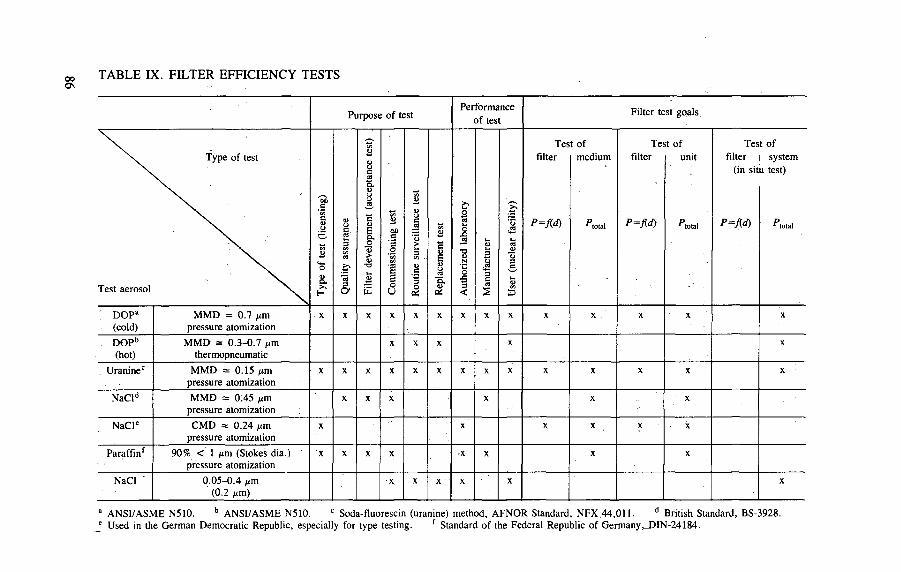
TABLE IX. FILTER EFFICIENCY TESTS
Purpose of test Performance
of test Filter test goals
Type of test
Test aerosol Type
of t
est
(lice
nsin
g)
Qua
lity
assu
ranc
e
Filte
r de
velo
pmen
t (a
ccep
tanc
e te
st)
Com
mis
sion
ing
test
Rou
tine
surv
eilla
nce
test
Rep
lace
men
t te
st
Aut
horiz
ed l
abor
ator
y
Man
ufac
ture
r
Use
r (n
ucle
ar f
acili
ty)
Tes filter
P=M
t of medium
^ to la l
Tes filter
P=M
t of unit
A o t a l '
Tes filter
(in sit
P=M
t of system
u test)
^ to ta l
; DOPa
(cold) MMD = 0.7 /im
pressure atomization X X X X X X X X X X X X X X
DOPb
(hot) MMD = 0.3-0.7 fim
thermopneumatic X X X X X
Uraninec MMD = 0.15 nm pressure atomization
X X X X X X X X X X X X X X
NaCld MMD = 0.45 /xm pressure atomization
X X X X X X
NaCle CMD = 0.24 |im pressure atomization
X X X X X X
Paraffinf 90% < 1 nm (Stokes dia.) pressure atomization
X X X X -X X X X
NaCl 0.05-0.4 jim (0.2 j » m )
X X X X X X
a ANSI/ASME N510. b ANSI/ASME N510. c Soda-fluorescin (uranine) method, AFNOR Standard, NFX 44,011. d British Standard, BS-3928. * Used in the German Democratic Republic, especially for type testing. f Standard of the Federal Republic of Germany,_DIN-24184.
(d) Sodium chloride aerosol method according to BS-3928 [58], Table IX (Method No. 4).
— Cubic solid particles, generated by pressure atomization of aqueous salt solu-tion and drying.
— Method of analysis: Flame photometer for measurement of total penetration. — Advantage: Equipment is available commercially and is relatively simple to
operate.
— Disadvantages:
(i) Safety problems in connection with the use of hydrogen for the flame photometer.
(ii) It is possible that the salt aerosol is corrosive in some situations.
— Limitations:
(i) Temperature up to 400°C. (ii) Relative humidity up to about 60%.
(e) Sodium chloride aerosol method used in the German Democratic Republic [52], Table IX (Method No. 5).
— Cubic solid particles, generated by pressure atomization of aqueous salt solu-tion and drying.
— Method of analysis: Scintillation particle spectrometer [57], or laser aerosol spectrometer (see Fig. 41) for measurement of P = fid) and total penetration.
— Advantage: The lower detection limit of the Sartorius scintillation particle pho-tometer corresponds to a crystal edge length of NaCl particles of about 0.03 nm.
— Disadvantage: Dilution equipment is necessary; for other disadvantages, see (d).
— Limitations: see (d).
( f ) Paraffin oil method according DIN 24184 [59], Table IX (Method No. 6)
— Liquid droplets, generated by pressure atomization. — Method of analysis. Photometer for measurement of total penetration (total
scattered light).
— Advantage: The equipment is available commercially and is relatively simple to operate.
— Disadvantage: The filter properties can be changed, especially for high aerosol concentrations.
87
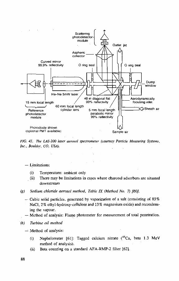
FIG. 41. The LAS-200 laser aerosol spectrometer (courtesy Particle Measuring Systems, Inc., Boulder, CO, USA).
— Limitations:
(i) Temperature: ambient only (ii) There may be limitations in cases where charcoal adsorbers are situated
downstream
(g) Sodium chloride aerosol method, Table IX (Method No. 7) [60].
— Cubic solid particles, generated by vaporization of a salt (consisting of 85% NaCl, 2% ethyl-hydroxy-cellulose and 13% magnesium oxide) and recondens-ing the vapour.
— Method of analysis: Flame photometer for measurement of total penetration.
(h) Turbine oil method
— Method of analysis:
(i) Nephelometer [61]: Tagged calcium nitrate (45Ca, beta 1.3 MeV method of analysis).
(ii) Beta counting on a standard AFA-RMP-2 filter [62],

— Advantage: The equipment is relatively easily portable.
— Disadvantages:
(i) Safety problems in connection with the use of mixed oxygen/propane gas required for salt vaporization and hydrogen gas for the flame photo-meter;
(ii) It is possible that the salt aerosol is corrosive in some situations.
— Limitations:
(i) Temperature up to 400°C, (ii) Relative humidity up to about 60%.
7.3. TEST METHODS FOR OTHER FILTER CHARACTERISTICS
Table X surveys the test methods used to determine other filter characteristics which are important for the behaviour of filters under different conditions.
8. HANDLING, STORAGE AND DISPOSAL OF CONTAMINATED FILTER INSERTS
8.1. REMOVAL AND BAGGING OF CONTAMINATED FILTER INSERTS
When there is any likelihood of the spread of contamination in unshielded systems during the change out of filter inserts, a safe change bogging procedure should be employed. The used filter inserts are transported, taking care to avoid bag puncture, to storage and/or disposal at the waste handling facility.
8.2. CLASSIFICATION AND STORAGE OF CONTAMINATED FILTER INSERTS
There are likely to be two storage requirements for filter inserts removed from filter systems, one local to the plant and the other with reference to a holding store prior to disposal. The extent of storage facilities required for contaminated filter inserts will depend on the degree of contamination and are largely determined by radiotoxicity and shielding considerations. Careful consideration should be given to changing inserts on the basis of activity buildup, rather than pressure drop. In some instances, an economic assessment will have to be made of the relative costs of storage and disposal of a large number of inserts of lower activity compared with
8 9
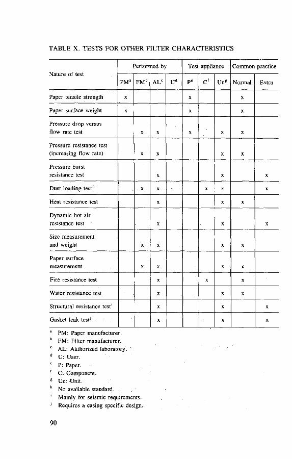
TABLE X. TESTS FOR OTHER FILTER CHARACTERISTICS
Nature of test Performed by Test appliance Common practice
Nature of test PM a FM b ALC Ud P c C f Ung Normal Extra
Paper tensile strength X X X
Paper surface weight X X X
Pressure drop versus flow rate test X X X X X
Pressure resistance test (increasing flow rate) X X X X
Pressure burst resistance test X X X
Dust loading testh X X X X X
Heat resistance test X X X
Dynamic hot air resistance test X X X
Size measurement and weight X X X X
Paper surface measurement X X X X
Fire resistance test X X X
Water resistance test X X X
Structural resistance test' X X X
Gasket leak testJ X X X
a PM: Paper manufacturer. b FM: Filter manufacturer. c AL: Authorized laboratory. d U: User. e P: Paper. f C. Component. 8 Un: Unit. h No .available standard. 1 Mainly for seismic requirements. 1 Requires a casing specific design.
90
fewer inserts of higher activity. The cost of new inserts is usually small compared with the cost of storage and disposal. The cost of storage of contaminated inserts may sometimes be reduced by the use of some form of pretreatment, such as shredding or compaction.
8.3. DISPOSAL OF CONTAMINATED FILTER INSERTS
Filter wastes are generally classified in terms of the alpha and gamma activity levels set for the disposal routes available or planned. Contaminated filters usually fall into one of the two categories described below.
8.3.1. Low level contaminated inserts
In this case, contamination and radiation levels are low enough for the wastes to be buried in specially engineered shallow landfill trenches, or according to national requirements. Current trends are toward the use of mild steel overpack drums. One possible disposal route would be compaction of low level waste (LLW) filter inserts within an appropriately sized mild steel drum with a PVC bag liner. Attention would have to be paid to the spread of activity during compaction, particu-larly when a filter has been bagged. Sudden pressure release from a compressed bag could lead to a wide dispersion of filter debris. This form of treatment has the advan-tage of requiring few process and handling stages. Where the rate of used filter insert generation is low, compaction may not be required and direct disposal in drums is possible.
8.3.2. Intermediate level contaminated inserts
Used filter inserts in this category will probably require disposal within an immobilizing (both mechanical and chemical) matrix contained in a stainless steel drum. In this case, some form of treatment may be economically attractive, but the analysis must take into account the dose detriment of any processes undertaken.
Treatment processes that have been investigated include:
(a) Dismantling. The filtration medium is compressed and disposed of as inter-mediate level waste (ILW). The case is disposed of as LLW. There is a risk of the spread of activity, and the processing plant can be complex as the filter medium may require baling or wetting to stop re-expansion after compression.
(b) Compaction. A four to five fold reduction in volume can be achieved by com-paction (4-5 t machines). This is similar to the process outlined in the previous section. For ILW, however, compaction within the final disposal drum and in-fill with an immobilizing matrix would probably give an unacceptable waste
91
form from the point of view of mechanical strength or migration of activity in the long term.
(c) Supercompaction. A large (more than twenty times) volume reduction factor can be achieved using 1000 t machines.
(d) Incineration. Either complete filter inserts or the filtration medium and spacers are fed to an incinerator. This gives the best volume reduction, but a complex ILW incinerator is required, which may have its own off-gas ventilation problems and may generate an unacceptably large number of filter inserts to be treated.
Items (c) and (d) can also be applied to LLW filters if this is economically attractive. In addition to the above, it is of course possible to immobilize uncompacted
filters directly in a disposal drum. None of the treatment and disposal options given above are in use as neither repository design nor waste form specifications have been agreed upon.
A major problem with exisiting ILW filter inserts is the presence of aluminium spacers. The favoured immobilizing matrix for the majority of ILW is based on cement. This gives good product strength and will give long term repository condi-tions (high pH) that will minimize nuclide migration in any groundwater that may permeate the repository. Unfortunately, the combination of an alkaline immobilizing matrix and high surface to volume ratio aluminium spacers present in filter inserts will produce large volumes of hydrogen. The large voids produced in the matrix severely weaken it and can seriously affect liquid phase nuclide migration. It should be noted that galvanized surfaces may also release hydrogen when in contact with alkaline grouts. In all new ventilation air filtration systems, where the inserts may become contaminated to ILW levels, it is vital to use inserts that do not contain aluminium.
9. TRENDS AND DEVELOPMENTS
HEPA filtration is a well established technology. Because HEPA technology already meets existing technical requirements for on-design conditions, the pace of development of HEPA filters has slowed in recent years. Further development is concerned not so much with improving filtration efficiency as with reducing the cost and increasing the convenience of use of HEPA filters and increasing their resistance to off-design conditions.
The main effort in development work in filtration technology has turned away from improving filters for nuclear plants and is now directed to filters for clean rooms in the semiconductor industry. The principal innovation in this area has been the development of ultralow penetration (ULPA) filters, which have penetrations of ~ 10"6 compared with ~ 10~3 for HEPA filters.
9 2

The more stringent requirements for testing ULPA filters compared with HEPA filters has resulted in much research effort being expended on improving filter testing equipment. It would not be surprising, therefore, if some instruments at present under development for testing ULPA filters also find application in the future in HEPA filter testing.
9.1. FILTER DESIGN
9.1.1. Improved filter media
Filter media with improved resistance to off-design conditions have been developed. Examples of such media are: stainless steel fibre filters and filters of sin-tered mixtures of stainless steel and quartz fibres. Both types of media have improved temperature resistance and mechanical stiffness, but they are considerably more expensive than standard HEPA filter media. Another filter medium that offers improved stiffness for a more modest increase in cost is a glass fibre paper with an integral woven glass fibre backing.
9.1.2. Filter geometry
The filtration efficiency of a standard HEPA filter in situ is normally much less than that of the filtration medium used in its construction. The reason for this reduced efficiency is leakage at seals. The seal on a standard square section HEPA filter would appear to be much less efficient in practice than the lip seal that can be used with a cylindrical filter geometry. Tests using cylindrical filters in place of stan-dard square section filters confirm that the efficiency of a cylindrical filter is greater in practice than that of a standard square section filter constructed of the same materials. Tests on the cylindrical filter lip seal have demonstrated penetrations that are better than ULPA penetration at rated airflow. A cylindrical filter geometry also offers advantages for the disposal of filters in waste drums.
9.1.3. Electric filters
Conventional HEPA filters have been converted to electric filters by using aluminium spacers, to which an electric potential is applied to achieve field strengths of up to 12 kV/cm. This type of filter offers much higher filtration efficiency at reduced pressure drop, thus enabling service life to be extended. The reduced pres-sure drop is believed to result from a more open, dendritic structure of the particle deposits on the filter. Even conventional HEPA filters can be electric filters to some extent because airflow through the filter can lead to electrostatic charging. Potential
9 3
differences of up to 2 kV have been measured on HEPA filters because of this type of charging.
9.1.4. Cleanable HEPA filters
Standard HEPA filter inserts are thrown away when the pressure drop becomes too high. This implies considerable costs for new inserts and disposal of the contami-nated inserts. Reuse is thus cost effective.
The FARTOS filter, described in Section 3.1.2.5, is designed for in situ clean-ing by spraying water or other solutions containing chemical agents. Filters with stainless steel fibres can, in principle, be washed.
Another development is to spray the glass fibre paper of a standard HEPA filter with a special coating. This coating has pores of about 1 nm and acts like a sieve. The original filter paper is then only a supporting base for the coating. When the pressure drop becomes too high the cake can be removed by backflushing with com-pressed air or by vacuum cleaning. Application will be restricted to process filtration and for recycling of valuable dusts. Although these filters are available commer-cially, development is still empirical; scientific and technical knowledge of the properties and behaviour is lacking. Furthermore, there is only limited experience in the use with radioactive aerosols.
9.1.5. Cleanable sintered metal filters [63]
Filter elements for heavy duties, with the suitability for in situ cleaning, have been used for specific gas filtration tasks for a considerable time in the nuclear and chemical industries. Metal fibres or powders in the range of 2—20 ^m in materials selected to be highly corrosion resistant are sinter bonded to act as a surface filter. Cleaning is generally by pulsed blowback [64].
9.2. FILTER TESTING
9.2.1. Retention efficiency
Previously, particle retention efficiency was measured at a single particle diameter at or near the peak value for particle penetration. More recently, HEPA penetration has also been characterized as a function of particle size over a range that covers the whole peak in penetration curve. The measurement may be made in two ways: (a) the filter is 'challenged' with a monodisperse aerosol and the penetration is measured with a condensation nucleus counter (CNC); (b) the filter is challenged
94
with a heterodisperse aerosol and the penetration is obtained by comparing the aero-sol upstream and downstream of the filter using, for example, a DMA/CNC for par-ticles <0 .2 /xm and a laser counter for larger particles. The sensitivity of either method is 10"7. With the recent availability of laser counters measuring down to 0.065 nm, most of the particle penetration peak can be covered with a single instru-ment. In the USA, standards exist for the routine characterization of filter media with this technique.
9.2.2. In situ tests
The application of a laser spectrometer as a detector for in situ testing of HEPA filters was investigated for the purpose of upgrading a standard leak test into an in situ test of filter efficiency. Sensitivity of better than 10"6 occurs in the range of 1-3 ^m.
9.2.3. Other test methods
The service life of a filter under on-design conditions is determined by filter loading. At present there is no standard test for this parameter. There is also no stan-dard test method for overpressure accident conditions, although an Organisation for Economic Co-operation and Development (OECD) report exists which could serve to establish the requirements of such a test.
9.3. FILTER INSERT DISPOSAL
At present, only low level contaminated filter inserts can be sent for disposal and filter inserts contaminated to intermediate level are stored. Compaction, super-compaction and incineration are being developed as treatments before packaging. For ILW, encapsulation within the waste package is usual in order to immobilize the activity before disposal. The generally favoured immobilizing medium is cement grout, but this is not compatible with filter components which contain aluminium, zinc or which are galvanized. These materials react with alkalinity generated in cement grout, producing hydrogen gas and gross voids within the matrix. Aluminium spacers are currently widely used.
95


REFERENCES
[1] INTERNATIONAL COMMISSION ON RADIOLOGICAL PROTECTION, Recom-mendations of the International Commission on Radiological Protection, ICRP Publica-tion 26, Pergamon Press, Oxford (1977).
[2] INTERNATIONAL ATOMIC ENERGY AGENCY, Air Filters for Use at Nuclear Facilities, Technical Reports Series No. 122, IAEA, Vienna (1970).
[3] INTERNATIONAL ATOMIC ENERGY AGENCY, Design and Operation of Off-Gas Cleaning Systems at High Level Liquid Waste Conditioning Facilities, Technical Reports Series No. 291, IAEA, Vienna (1988).
[4] INTERNATIONAL ATOMIC ENERGY AGENCY, Treatment of Off-Gas from Radioactive Waste Incinerators, Technical Reports Series No. 302, IAEA, Vienna (1989).
[5] INTERNATIONAL ATOMIC ENERGY AGENCY, Design of Off-Gas and Air Cleaning Systems at Nuclear Power Plants, Technical Reports Series No. 274, IAEA, Vienna (1987).
[6] INTERNATIONAL ATOMIC ENERGY AGENCY, Testing and Monitoring of Off-Gas Cleanup Systems at Nuclear Facilities, Technical Reports Series No. 243, IAEA, Vienna (1984).
[7] INTERNATIONAL ATOMIC ENERGY AGENCY, Design and Operation of Off-Gas Cleaning and Ventilation Systems in Facilities Handling Low and Intermediate Level Radioactive Material, Technical Reports Series No. 292, IAEA, Vienna (1988).
[8] DA VIES, C., Air Filtration, Academic Press, New York (1973). [9] PICH, J., Filtration — Principles and Practice (ORR, C., Ed.), Part I, Chapter 1,
Marcel Dekker, New York (1977). [10] KIRSCH, A., STECHKINA, I., Fundamentals of Aerosol Science (SHAW, D., Ed.),
Chapter 4, Wiley-Interscience, New York (1978). [11] BERGMAN, W., et al., Electric Air Filtration: Theory, Laboratory Studies, Hardware
Development and Field Evaluations, Rep. UCID-19952, Lawrence Livermore National Laboratory, Livermore, CA (1984).
[12] KUWABARA, S., The forces experienced by randomly distributed parallel circular cylinders or spheres in viscous flow at small Reynolds Nos, J. Phys. Soc. Jpn 14 (1959) 527.
[13] BANKS, D. , KUROWSKI, G. , Perturbation model for the computation of collection efficiency for axially symmetric collectors, Aerosol Sci. Technol. 33 (1984) 317-326.
[14] BANKS, D., KUROWSKI, G., Diffusion deposition on a cylinder due to nearly parallel collectors, Aerosol Sci. Technol. 8 (1988) 189-196.
[15] SCHOLTEN, L., LETSCHERT, P., Rep. CSNI-83, Committee on the Safety of Nuclear Installations, Nuclear Energy Agency of the OECD, Paris (1983) 453-466.
[16] BIERMANN, A., LUM, B., BERGMAN, W., "Evaluation of permanently charged electrofibrous fi l ters", Nuclear Air Cleaning (Proc. 17th USDOE Conf. Denver, 1982) (FIRST, M.W., Ed.), CONF-820833, National Technical Information Service, Spring-field, VA (1983) 523.
97

[17] BERGMAN, W., HEBARD, H., TAYLOR, R., LUM, B., "Electrostatic filters generated by electric fields", Proc. 2nd World Filtration Congress, Filtration Society, Croydon, UK (1979).
[18] BERGMAN, W., An Electric HEPA Filter, Rep. UCRL-50007-84, Lawrence Liver-more National Laboratory, Livermore, CA (1984) 65-68.
[19] LEE, K. W. , LIU, B.Y., On the minimum efficiency and most penetrating particle size for fibrous filters, Int. J. Air Pollution Control Assoc. 30 4 (1980) 377-381.
[20] LETOURNEAU, P., MULCEY, P., VENDEL, J., "Prediction of HEPA filter pres-sure drop and removal efficiency during dust loading", Nuclear Air Cleaning (Proc. 20th USDOE/USNRC Conf. Boston, 1988) (FIRST, M.W. Ed.), CONF-880815, National Technical Information Service, Springfield, VA (1989).
[21] FUKS, N.A. , The Mechanics of Aerosols, Pergamon Press, Oxford (1964) 27 (trans-lated from the Russian: Mekhanika Aerozolej (1955)).
[22] FUKS, N. , Usp. Mekhaniki Aerosolei (1961). [23] AEROV, M. , TODES, O., NARINSKY, D., Apparaty so Statsionarnym Zernistym
Sloem, Khimia Leningrad (1979). [24] KOPS, J., et al., "Penetration of ultra-fine particles through HEPA filters", Gaseous
Effluent Treatment in Nuclear Installations (Proc. CEC European Conf. Luxembourg, 1985) (FRASER, G., LUYKX, F. , Eds), Graham and Trotman, London (1986) 73-85.
[25] INTERNATIONAL ATOMIC ENERGY AGENCY, Retention of Iodine and Other Airborne Radionuclides in Nuclear Facilities during Abnormal and Accident Condi-tions, IAEA-TECDOC-521, Vienna (1989).
[26] ALKEN, W. et al., "Development of a HEPA filter with high structural strength and resistance to the effects of humidity and acid", Nuclear Airborne Waste Management and Air Cleaning (Proc. 18th USDOE Conf. Baltimore, 1984) (FIRST, M.W., Ed.), CONF-840806, National Technical Information Service, Springfield, VA (1985) 1085.
[27] ALVARES, M., et al., "Fire protection countermeasures for containment ventilation systems", Nuclear Air Cleaning (Proc. 16th USDOE Conf. San Diego, 1980) (FIRST, M.W., Ed.), CONF-801038, National Technical Information Service, Spring-field, VA (1981).
[28] BRIAND, A., LABORDE, J. , MULCEY, P., SAVORNIN, J., TESSIER, J., "Analy-sis and consequences of fire inside the ventilation ducts of a nuclear facility", Proc. ASHRAE Congress for 'HVAC' for Nuclear Facilities, Vancouver, 1989 (to be published).
[29] PETRIANOV, J., KOZLOV, V. S., BASMANOV, P., OGORODNIKOV, B., Voloknistiye filtruyushchiye materialy F.P. , Znaniye, Seriya 'Khimiya', Moscow (1968).
[30] DIN, DEUTSCHES INSTITUT FUR NORMUNG eV, Normenausschuss Kern-technik, DIN-24185, Teil 2, DIN, Berlin (Oct. 1980).
[31] SOKOLOV, V., SEVASTIANOV, F., LINDE U., NOVOSELOVA, M., Filtry FARTOS, Atominform, Moscow (1984).
[32] ULLMANN, W., HAMEL, P., SCHULTZ, W. , "Filter testing under special condi-t ions", Retention of Iodine and Other Airborne Radionuclides in Nuclear Facilities dur-ing Abnormal and Accident Conditions, IAEA-TECDOC-521, IAEA, Vienna (1989) 37-62.
98

[33] ROBINSON, K., et al., ' 'In-service ageing effects on HEPA filters'', Gaseous Effluent Treatment in Nuclear Installations (Proc. CEC European Conf. Luxembourg, 1985) (FRASER, G., LUYKX, F. , Eds), Graham and Trotman, London (1986).
[34] BERGMAN, W., et al. "Electrofibrous prefilters for use in nuclear ventilation systems", Nuclear Air Cleaning (Proc. 16th USDOE Conf. San Diego, 1980) (FIRST, M.W., Ed.), CONF-801038, National Technical Information Service, Spring-field, VA (1981).
[35] BURKHOLTZ, A., in Air Pollution Control, Part IV (BRAGG, G.M., STRAUSS, J. , Eds), Wiley-Interscience, New York (1981).
[36] SAVORNIN, J., "General considerations on fire and explosions in a nuclear facility. Interaction with ventilation", Interaction of Fire and Explosion with Ventilation Sys-tems in Nuclear Facilities (Proc. CSNI Specialists Mtg Los Alamos, 1983), Rep. LA-9911-C-Vol. 1, National Technical Information Service, Springfield, VA (1983).
[37] Filtered Containment Venting Systems (Proc. CSNI Specialists Mtg Paris, 1988), Rep. CEA-DAS-511 (1988) (available from INIS, IAEA, Vienna).
[38] BENJAMIN, A., STRIP, D., "Cost benefit considerations for filtered-vented contain-ment systems", Nuclear Air Cleaning (Proc. 17th USDOE Conf. Denver, 1982) (FIRST, M.W., Ed.), National Technical Information Service, Springfield, VA (1983).
[39] Project FILTRA, Final Report, Nov. 1982, Rep. S-61182, Studsvik Library, Nykoping (1982).
[40] ELISSON, K., " A multi-venturi scrubber system for containment venting", Filtered Containment Venting Systems (Proc. CSNI Specialists Mtg Paris, 1988), Rep. CEA-DAS-511 (1988) (available from INIS, IAEA, Vienna.)
[41] JOUEN, E., "Containment venting system — sand bed filter: description, operating procedure, implementation programme and associated research and development", ibid.
[42] DILLMANN, H., PASLER, H., WILHELM, J. , Containment venting filter design incorporating stainless steel fibre filters, Kerntechnik 53 1 (1988) 75-80.
[43] ECKERT, B., Containment venting for light water reactor plants, Kerntechnik 53 1 (1988) 81-82.
[44] ARRU, L., SGALAMBRO, G., "Containment venting alternatives in Italian BWRs: A preliminary approach", Severe Accidents in Nuclear Power Plants (Proc. Int. Symp. Sorrento, 1988), Vol. 2, IAEA, Vienna (1988) 697-714.
[45] ARROW, L. ARRU, L., SGALAMBRO, G., "Outlines of a possible strategy for con-tainment ventilation", Filtered Containment Venting Systems (Proc. CSNI Specialists Mtg Paris, 1988), Rep. CEA-DAS-511 (1988) (available from INIS, IAEA, Vienna.)
[46] INTERNATIONAL ORGANIZATION FOR STANDARDIZATION, Fundamental Principles for Protection in the Design and Construction of Installations for Work on Unsealed Radioactive Material, Draft ISO Recommendation 1710, ISO, Geneva (1968).
[47] INTERNATIONAL ATOMIC ENERGY AGENCY, Techniques for Controlling Air Pollution from the Operation of Nuclear Facilities, Safety Series No. 17, IAEA, Vienna (1966).
99

[48] BURCHSTED, C. A., KAHN, J.E., FULLER, A.B., "Design, construction and test-ing of high efficiency air cleaning systems for nuclear application", Nuclear Air Clean-ing Handbook, Rep. ERDA-76-21, United States Energy Research and Development Administration, Washington, DC (1976).
[49] SILVERMAN, L., BILLINGS, C.E., FIRST, M.W., Particle Size Analysis in Indus-trial Hygiene, Academic Press, New York (1981).
[50] HERDAN, G., Small Particle Statistics, Elsevier Publishing, New York (1953). [51] LASSEN, L., RAN, G., Die Anlagerung radioactiver Atome an Aerosole, Z. Phys.
160 (1960) 504. [52] ULLMANN, W., PRZYBOROWSKI, S., "Comparison of testing methods forparticu-
late filters", Comparison of High Efficiency Particulate Filter Testing Methods, IAEA-TECDOC-355, IAEA, Vienna (1985) 31-58.
[53] AMERICAN SOCIETY of MECHANICAL ENGINEERS, Testing of Nuclear Air Cleaning Systems, ANSI-ASME-N-510, ASME New York (1980).
[54] DEWORM, J. , et al., The Application of Laser Detectors to the Testing of High Efficiency Particulate Air Filtration in the Nuclear Industry and a Comparison with Conventional Detectors, Rep. CEC-DOC-V/6417/82, Directorate of Health Protection, Commission of the European Communities, Luxembourg (1982).
[55] MARSHALL, M., STEVENS, D., " A comparative study of in-situ filter test methods", Nuclear Air Cleaning (Proc. 16th USDOE Conf. San Diego, 1980) (FIRST, M.W., Ed.), CONF-801038, National Technical Information Service, Springfield, VA (1981).
[56] DUPOUX, J., "In-situ measurement of the efficiency of filtering installations in the nuclear industry by the soda-fluorescein (uranine) aerosol method, AFNOR standard NFX 44.011" , ibid.
[57] BINEK, B., DOHNALOVA, B., PRZYBOROWSKI, S., ULLMANN, W., Die Anwendung des Scintillations-Spektralanalysators fiir Aerosole in Forschung und Technik, Staub 27 (1967) 379.
[58] BRITISH STANDARDS INSTITUTION, Methods of Test for Low-Penetration Air Filters, BS-3928, BSI, London (1965).
[59] DIN, DEUTSCHES INSTITUT FUR NORMUNG eV, Normenausschuss Kerntech-nik, DIN-24184, Typpriifung von Schwebstoffiltern, DIN, Berlin (Oct. 1974).
[60] DORMAN, R.G., et al., ' 'The sodium chloride aerosol test for high efficiency air filter installations", High Efficiency Aerosol Filtration in the Nuclear Industry (Proc. Semi-nar Aix-en-Provence, 1976), Commission of the European Communities, Luxembourg (1977).
[61] Promyshlennye filtruyushch protivogazy i respiratory GOST 20810-75, Gosstandard, Moscow (1975).
[62] WAIT A, P., SMITA, S. (Eds), Vysokoeffektivnaya ochistka vozduha. Atomizdat, Moscow (1967).
[63] MEDDINGS, P., OATES, P. , "Gas reactor experience and development studies with metal filters", Proc. Conf. Gas Cleaning in the Nuclear Industry, 1984, Filtration Soci-ety, Croydon, UK.
[64] PICKARD, P., PERRY, R.A., "Cleaning metal filters by pulse-jet", Gaseous Effluent Treatment in Nuclear Installations (Proc. CEC European Conf. Luxembourg, 1985) (FRASER, G., LUYKX, F. , Eds), Graham and Trotman, London (1986).
100

CONTRIBUTORS TO DRAFTING AND REVIEW
1: Consultants Meeting
Vienna, 25-29 January 1988
2: Technical Committee Meeting
Vienna, 30 May-3 June 1988
Bergman, W. (2) (Chairman)
Dillmann, H .G. (1)
First, M.W. (1)
Friedrich, V. (1, 2) (Scientific Secretary)
Kazankin, J .N. (2)
Kochetkov, O.A. (2)
Leonardi, A. (2)
Mulcey, P. (2)
Parkin, P .H. (2)
Pickering, S. (2)
Rastunov, L .N. (2)
Lawrence Livermore National Laboratory, United States of America
Kernforschungszentrum Karlsruhe, Germany
School of Public Health, Harvard University, United States of America
International Atomic Energy Agency
V.G. Khlopin Radium Institute, Union of Soviet Socialist Republics
Institute of Biophysics, USSR State Committee on Utilization of Nuclear Energy,
Union of Soviet Socialist Republics
Comitato Nazionale per la Ricerca e per lo Sviluppo dell 'Energia Nucleare et delle Energie Alternative,
Italy
Centre d'etudes nucl6aires de Saclay, France
Ontario Hydro, Canada
Joint Research Centre, Commission of the European Communities, Karlsruhe, Germany
All-Union Scientific and Research Institute for Inorganic Materials,
Union of Soviet Socialist Republics

Robinson, K.S. (1, 2)
Scholten, L.C. (2)
Ullmann, W. (2)
UKAEA/Harwell Laboratory. United Kingdom
Keuring van Elektrotechnische Materialen (KEMA), NV,
Netherlands
National Board of Atomic Safety and Radiation Protection,
Germany
102

HOW TO ORDER IAEA PUBLICATIONS An exclusive sales agent for IAEA publications, to whom all orders
and inquiries should be addressed, has been appointed for the following countries:
CANADA UNITED STATES O F AMERICA UNIPUB, 4611-F Assembly Drive, Lanham, MD 20706-4391, USA
In the following countries IAEA publications may be purchased from the sales agents or booksellers listed or through major local booksellers. Payment can be made in local currency or with UNESCO coupons.
ARGENTINA
AUSTRALIA BELGIUM
CHILE
CHINA
CZECHOSLOVAKIA
FRANCE
HUNGARY
INDIA
ISRAEL
ITALY
JAPAN PAKISTAN
POLAND
ROMANIA SOUTH AFRICA
SPAIN
SWEDEN
UNITED KINGDOM
USSR YUGOSLAVIA
Comision Nacional de Energi'a Atomica, Avenida del Libertador 8250, RA-1429 Buenos Aires Hunter Publications, 58 A Gipps Street, Collingwood, Victoria 3066 Service Courrier UNESCO, 202, Avenue du Roi,B-1060 Brussels Comisi6n Chilena de Energia Nuclear, Venta de Publicaciones, Amunategui 95,Casilla 188-D, Santiago IAEA Publications in Chinese: China Nuclear Energy Industry Corporation,Translation Section, P.O. Box 2103, Beijing IAEA Publications other than in Chinese: China National Publications Import & Export Corporation, Deutsche Abteilung, P.O. Box 88, Beijing S.N.T.L., Mikulandska 4,CS-116 86 Prague 1 Alfa, Publishers, Hurbanovo namestie 3, CS-815 89 Bratislava Office International de Documentation et Librairie,48, rue Gay-Lussac, F-75240 Paris Cedex 05 Kultura, Hungarian Foreign Trading Company, P.O. Box 149, H-1389 Budapest 62 Oxford Book and Stationery Co., 17, Park Street, Calcutta-700 016 Oxford Book and Stationery Co.,Scindia House, New Delhi-110001 Heiliger & Co. Ltd. 23 Keren Hayesod Street, Jerusalem 94188 Libreria Scientifica, Dott. Lucio de Biasio "aeiou". Via Meravigli 16, 1-20123 Milan Maruzen Company, Ltd, P.O. Box 5050,100-31 Tokyo International Mirza Book Agency,65, Shahrah Quaid-e-Azam, P.O. Box 729, Lahore 3 Ars Polona-Ruch, Centrala Handlu Zagranicznego, Krakowskie Przedmiescie 7, PL-00-068 Warsaw llexim, P O. Box 136-137, Bucharest Van Schaik Bookstore (Pty) Ltd, P.O. Box 724, Pretoria 0001 Diaz de Santos, Lagasca 95, E-28006'Madrid Diaz de Santos, Balmes 417, E-08022 Barcelona AB Fritzes Kungl. Hovbokhandel, Fredsgatan 2, P.O. Box 16356, S-103 27 Stockholm HMSO, Publications Centre, Agency Section, 51 Nine Elms Lane, London SW8 5DR Mezhdunarodnaya Kniga.Smolenskaya-Sennaya 32-34, Moscow G-200 Jugoslovenska Knjiga,Terazije 27.P.O. Box 36, YU-11001 Belgrade
Orders from countries where sales agents have not yet been appointed and requests for information should be addressed directly to:
^ Division of Publications H International Atomic Energy Agency
' Wagramerstrasse 5, P.O. Box 100, A-1400 Vienna, Austria

0) 0)

INTERNATIONAL ATOMIC ENERGY AGENCY VIENNA, 1991