partner update s ummer - us epa · pdf fileexhibit leakage problems than valves in crude oil...
TRANSCRIPT

PARTNER UPDATE SUMMER 2010
Prospective Projects Spotlight: Valve Maintenance and Leak Mitigation This article describes a project to begin or enhance the use of cleaners, lubricants, and sealants on valves as part of their maintenance schedules. Valves can be a significant source of methane emissions as scars on seating surfaces develop and create unintended pathways across the valve, causing fugitive emissions. Valves in natural gas service are more likely to exhibit leakage problems than valves in crude oil service for the simple reason that the oil itself is self-lubricating and dry natural gas is not. The emissions that can result are leakage across shut valves or venting of the line to take it out of service for valve replacement. Major valve leakage can be mitigated by implementing a regular valve maintenance program as a cost-effective alternative to valve replacement. This can apply to mainline valves as wells as compressor blowdown and isolation valves. This article will give additional background on valve leaks, describe valve maintenance and repair, and provide example implementation economics.
Partner Update Summer 2010
1
SAVE THE DATE 2010 Annual Implementation Workshop
November 1 to 3, 2010 Ritz Carlton New Orleans, Louisiana The Annual Implementation Workshop is an opportunity for information exchange about cost-effective methane emissions reduction methods. It will bring together Natural Gas STAR domestic and international Partners and industry experts to discuss the latest technologies and practices. This year, the workshop will feature an expanded exhibitor area in addition to the optional facility site tours highlighting various methane emissions detection, measurement, and reduction methods at nearby operating facilities. Conference updates, registration, and hotel information will be posted to the Natural Gas STAR web site: epa.gov/gasstar/workshops. For information, please contact Jerome Blackman ([email protected]).

Background: Methane Emissions from Valve Leaks Exhibit 1 below shows a list of valves commonly encountered at natural gas facilities along with average methane emissions factors. Blowdown and unit valves account for a majority of emissions since they are associated with large gas volumes and have long service lives. Exhibit 1: Average Fugitive Emissions Factors for Equipment Leaks from Compressor Station Components
Emission source
Typical emission factor (Mcf/Year/Component)1
Und
er M
ain
Line
Pr
essu
re2 Unit Valve 3,566
Blowdown Valve 207.5 (±171.4) Open-Ended Line (OEL) 81.8 (±79.6) Ball/Plug Valve 5.33 (±3.71) Gate Valve 0.61 (±0.43)
Und
er F
uel
Gas
Pre
ssur
e3 Open-Ended Line (OEL) 2.53 (±2.19)
Ball/Plug Valve 0.51 (±0.37) Gate Valve 0.43 (±0.36)
Source: EPA Natural Gas STAR. Lessons Learned: Directed Inspection and Maintenance at Compressor Stations. October 2003. page 10. 1Emission factors with associated 95 percent confidence intervals. 2Main line pressure ranges from 500 psig to 1,000 psig. 3Fuel gas pressure is typically 70 psig to 100 psig. Regular Valve Maintenance and Repair: Major Considerations Emissions prevention and reduction from valves can be accomplished through a combination of routine preventative maintenance and repair with application of cleaner, lubricant, and sealant. A major advantage of this project is that the valves can be maintained and repaired while online and under pressure, eliminating the costs associated with shutting down a line for valve replacement. Repair and maintenance practices are applicable for all valve sizes and types—from small valves (~1/2”) to the larger transmission valves (~60”) and for ball, plug, or gate valves Requirements In general, this project has only material and manpower requirements. No operating or process changes are required to implement regular valve maintenance, and it can be incorporated into routine operator activities. Materials required include cleaner, lubricant/sealant, heavy grade sealant, injection guns, stem packing, fitting caps, an injection fitting adaptor kit, and an air compressor. For a single large pipeline valve, the manpower required for this project is up to three operators (10 hours each) for the first year and one operator (10 hours) in subsequent years. Description
Partner Update Summer 2010
2
Gas leaks occur in three main locations on the valve: 1) sealing seat (internal leakage), 2) stem packing, and 3) valve fittings. These emission sources can be seen in Exhibit 2 of a typical ball valve. In the diagram, the ball valve is in the closed position, with the through-port
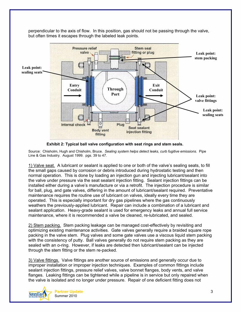
perpendicular to the axis of flow. In this position, gas should not be passing through the valve, but often times it escapes through the labeled leak points. Exhibit 2: Typical ball valve configuration with seat rings and stem seals. Source: Chisholm, Hugh and Chisholm, Bruce. Sealing system helps detect leaks, curb fugitive emissions. Pipe Line & Gas Industry. August 1999. pgs. 39 to 47. 1) Valve seat. A lubricant or sealant is applied to one or both of the valve’s sealing seats, to fill the small gaps caused by corrosion or debris introduced during hydrostatic testing and then normal operation. This is done by loading an injection gun and injecting lubricant/sealant into the valve under pressure via the seat sealant injection fitting. Sealant injection fittings can be installed either during a valve’s manufacture or via a retrofit. The injection procedure is similar for ball, plug, and gate valves, differing in the amount of lubricant/sealant required. Preventative maintenance requires the routine use of lubricant on valves, ideally every time they are operated. This is especially important for dry gas pipelines where the gas continuously weathers the previously-applied lubricant. Repair can include a combination of a lubricant and sealant application. Heavy-grade sealant is used for emergency leaks and annual full service maintenance, where it is recommended a valve be cleaned, re-lubricated, and sealed. 2) Stem packing. Stem packing leakage can be managed cost-effectively by revisiting and optimizing existing maintenance activities. Gate valves generally require a braided square rope packing in the valve stem. Plug valves and some gate valves use a viscous liquid stem packing with the consistency of putty. Ball valves generally do not require stem packing as they are sealed with an o-ring. However, if leaks are detected then lubricant/sealant can be injected through the stem fitting or the stem re-packed. 3) Valve fittings. Valve fittings are another source of emissions and generally occur due to improper installation or improper injection techniques. Examples of common fittings include sealant injection fittings, pressure relief valves, valve bonnet flanges, body vents, and valve flanges. Leaking fittings can be tightened while a pipeline is in service but only repaired when the valve is isolated and no longer under pressure. Repair of one deficient fitting does not
Partner Update Summer 2010
3
Through Port
Entry Conduit
Exit Conduit
Leak point: sealing seats
Leak point: valve fittings
Leak point: stem packing
Leak point: sealing seats
Partner Update Summer 2010
4
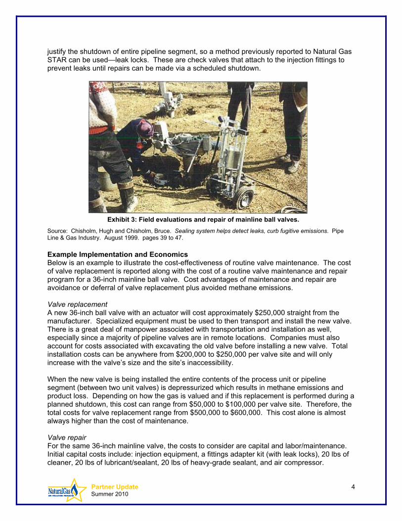
Exhibit 3: Field evaluations and repair of mainline ball valves.
justify the shutdown of entire pipeline segment, so a method previously reported to Natural Gas STAR can be used—leak locks. These are check valves that attach to the injection fittings to prevent leaks until repairs can be made via a scheduled shutdown.
Source: Chisholm, Hugh and Chisholm, Bruce. Sealing system helps detect leaks, curb fugitive emissions. Pipe Line & Gas Industry. August 1999. pages 39 to 47. Example Implementation and Economics Below is an example to illustrate the cost-effectiveness of routine valve maintenance. The cost of valve replacement is reported along with the cost of a routine valve maintenance and repair program for a 36-inch mainline ball valve. Cost advantages of maintenance and repair are avoidance or deferral of valve replacement plus avoided methane emissions. Valve replacement A new 36-inch ball valve with an actuator will cost approximately $250,000 straight from the manufacturer. Specialized equipment must be used to then transport and install the new valve. There is a great deal of manpower associated with transportation and installation as well, especially since a majority of pipeline valves are in remote locations. Companies must also account for costs associated with excavating the old valve before installing a new valve. Total installation costs can be anywhere from $200,000 to $250,000 per valve site and will only increase with the valve’s size and the site’s inaccessibility. When the new valve is being installed the entire contents of the process unit or pipeline segment (between two unit valves) is depressurized which results in methane emissions and product loss. Depending on how the gas is valued and if this replacement is performed during a planned shutdown, this cost can range from $50,000 to $100,000 per valve site. Therefore, the total costs for valve replacement range from $500,000 to $600,000. This cost alone is almost always higher than the cost of maintenance. Valve repair For the same 36-inch mainline valve, the costs to consider are capital and labor/maintenance. Initial capital costs include: injection equipment, a fittings adapter kit (with leak locks), 20 lbs of cleaner, 20 lbs of lubricant/sealant, 20 lbs of heavy-grade sealant, and air compressor.
Altogether these total to be approximately $20,000, for the injection instrument, adapter kit, and air compressor. Annual material costs are for refills of cleaner, lubricant, and sealant. 20 lbs of each will last approximately one year per large valve, assuming maintenance is performed every three weeks. Annual labor and maintenance is estimated to be $1,600 per valve for a three-person team, spending 10 hours per person.
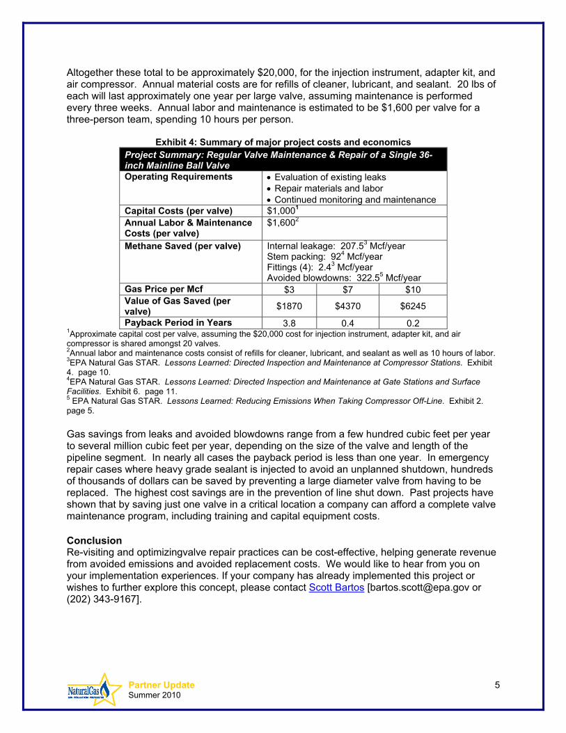
Exhibit 4: Summary of major project costs and economics Project Summary: Regular Valve Maintenance & Repair of a Single 36-inch Mainline Ball Valve Operating Requirements • Evaluation of existing leaks
• Repair materials and labor • Continued monitoring and maintenance
Capital Costs (per valve) $1,0001 Annual Labor & Maintenance Costs (per valve)
$1,6002
Methane Saved (per valve) Internal leakage: 207.53 Mcf/year Stem packing: 924 Mcf/year Fittings (4): 2.43 Mcf/year Avoided blowdowns: 322.55 Mcf/year
Gas Price per Mcf $3 $7 $10 Value of Gas Saved (per valve) $1870 $4370 $6245
Payback Period in Years 3.8 0.4 0.2 1Approximate capital cost per valve, assuming the $20,000 cost for injection instrument, adapter kit, and air compressor is shared amongst 20 valves. 2Annual labor and maintenance costs consist of refills for cleaner, lubricant, and sealant as well as 10 hours of labor. 3EPA Natural Gas STAR. Lessons Learned: Directed Inspection and Maintenance at Compressor Stations. Exhibit 4. page 10. 4EPA Natural Gas STAR. Lessons Learned: Directed Inspection and Maintenance at Gate Stations and Surface Facilities. Exhibit 6. page 11. 5 EPA Natural Gas STAR. Lessons Learned: Reducing Emissions When Taking Compressor Off-Line. Exhibit 2. page 5. Gas savings from leaks and avoided blowdowns range from a few hundred cubic feet per year to several million cubic feet per year, depending on the size of the valve and length of the pipeline segment. In nearly all cases the payback period is less than one year. In emergency repair cases where heavy grade sealant is injected to avoid an unplanned shutdown, hundreds of thousands of dollars can be saved by preventing a large diameter valve from having to be replaced. The highest cost savings are in the prevention of line shut down. Past projects have shown that by saving just one valve in a critical location a company can afford a complete valve maintenance program, including training and capital equipment costs. Conclusion Re-visiting and optimizingvalve repair practices can be cost-effective, helping generate revenue from avoided emissions and avoided replacement costs. We would like to hear from you on your implementation experiences. If your company has already implemented this project or wishes to further explore this concept, please contact Scott Bartos [[email protected] or (202) 343-9167].
Partner Update Summer 2010
5

Technology Spotlight: Clean Development Mechanism Flare and Vent Reduction Projects The Winter 2009 Partner Update described developments associated with the Kyoto Protocol’s Clean Development Mechanism (CDM) project methodology to reduce fugitive methane emissions at gas transmission stations, AM0023. In addition to this approved methodology, there are a number of others applicable to the oil and gas industry including AM0009, AM0037, AM0043, and AM0077. AM0009 addresses the recovery and utilization of flared or vented gas from oil wells, and it has the greatest number of implemented projects. This article focuses on AM0009 and summarizes how it is important to help reduce emissions from the oil and gas industry. CDM is an arrangement under the Kyoto Protocol that allows industrialized countries (Annex I countries) to achieve compliance with their reduction commitments. Through this mechanism, Annex I countries can establish emission reduction projects in developing countries as an alternative to more expensive emission reductions in their own countries. This is designed to allow for global GHG emission reductions at a lower global cost. After a validation and registration process, certified emission reductions (CERs) are issued where 1 CER = 1 tonne of carbon dioxide equivalent (tCO2e). Each CDM project undertaken is based on an Approved Methodology (AM) that describes a specific procedure for obtaining CERs. In particular, AM0009 is a methodology of specific relevance to the activities of Natural Gas STAR Partners. It outlines the “recovery and utilization of gas from oil wells that would otherwise be flared or vented.” AM0009 describes a procedure for companies looking to recover and utilize associated gas and/or lift gas and transport it to treatment facilities and then markets. The methodology first establishes the requirements to start a new project activity. It then lays out a baseline procedure by defining project boundaries and giving a stepwise process for demonstrating additionality. The quantity of reductions over the life span of the project equates to the total amount of CERs. There are currently seven AM0009 projects around the globe that have been registered by the CDM Executive Board (EB). An additional nine AM0009 projects are also at validation, which is part of the approval process. The registered projects are estimated to reduce 8,207,000 tCO2e/year. By 2012, it is estimated that the seven AM0009 projects will have accumulated 42,464,000 tCO2e. One example AM0009 project is the Rang Dong oil field in Vietnam. This CDM project has been in effect since December 2001 and generates 677,000 tCO2e/year in emissions reductions. By the end of its 10-year life span, it will have attained 6,770,000 total CERs. Another AM0009 project currently undergoing validation is the Guneshli oil and gas field in Azerbaijan. It is projected to save 1,114,000 tCO2e through 2012 by recovering and transporting previously vented associated gas. Assuming a CER price of $10, over $424 million in revenue will have been generated from the seven registered AM0009 projects alone at the close of 2012. These projects illustrate one of the several ways that methane emissions can be valued and make capture/reduction projects a productive investment of capital.
Partner Update Summer 2010
6

Partner Update Summer 2010
7
More information on AM0009 is available at cdm.unfccc.int/methodologies/DB/42X5O8TG3PI07L6WX4YVQNV4ZB12X9/view.html The list of approved methodologies is available at cdm.unfccc.int/methodologies/PAmethodologies/approved.html More information on the use of AM0009 at the Rang Dong oil field in Vietnam is available at cdm.unfccc.int/Projects/DB/DNV-CUK1133472308.56 More information on the use of AM0009 at the Guneshli oil and gas field in Azerbaijan is available at cdm.unfccc.int/Projects/Validation/DB/0XPKHKKIRQAEH8U9ZFLFHKGO6HTY7N/view.html Climate Policy Update: Approval of a New Carbon Offset Methodology for the U.S. Oil and Gas Industry On March 29, 2010 the American Carbon Registry (ACR) announced its approval of the first carbon offset methodology in the U.S. that applies to methane emissions in the oil & gas industry. Specifically, this methodology will allow oil & gas companies to generate carbon credits by retrofitting or replacing existing high-bleed pneumatic devices with low-bleed alternatives. This article summarizes the new methodology. The conversion of high-bleed pneumatics to low-bleed has been a gradual process in the oil & gas industry. Voluntary replacements and retrofits have been encouraged by the Natural Gas STAR Program since its inception because high-bleed devices are among the largest sources of vented methane in the oil & gas industry. As of April 2010, Natural Gas STAR Partners have saved 22.7 billion cubic feet (Bcf) by converting high-bleed devices to low-bleed1. Although economically favorable, progress has been hampered largely because of companies’ affinity for the status quo and a “if it’s not broke, don’t fix it” mentality. Reasons stated in the baseline methodology report include: high-bleed devices already work well, the complexity of company-wide retrofits, and the smaller economic value of the retrofits compared to other investment opportunities. The ACR’s approval of a pneumatic device methodology is aimed to provide more incentive for U.S. companies previously unwilling to convert their high-bleeds. Earning carbon credits will now allow companies to profit from the combined revenue streams of selling credits and the economic return of converting pneumatic devices. The new methodology only focuses on the retrofit of existing high bleed infrastructure and specifically excludes new well-sites installation where the use of low bleed controllers can be considered common practice. Devon Energy Corporation and Verdeo Group, Inc. worked collaboratively to develop this new ACR methodology. It is the first in a suite of methodologies being developed that focus on reducing methane emissions from oil and gas infrastructure. Its approval has encouraged Devon to undertake a company-wide retrofit of its high-bleed pneumatic devices. 1 EPA. 2010 U.S. Greenhouse Gas Inventory Report. epa.gov/climatechange/emissions/usinventoryreport.html.

The ACR is a non-profit, voluntary U.S. carbon market registry. Many of its members are Fortune 500 companies as well as mission-driven institutions and non-profit organizations. Companies that enroll new reduction projects in the ACR are called Project Proponents. Members of the ACR have access to its registry and technical services, where the ultimate goal of the ACR is to provide transparency and clear ownership Carbon offsets are measured in emission reduction tons (ERTs, where 1 ERT = 1 tonne carbon dioxide equivalent [tCO2e]) and are granted through company projects that follow the structure of a selected ACR standard or methodology. Similar to the Clean Development Mechanism (CDM) under the Kyoto Protocol, companies can create emission reduction projects based on established methodologies, or they can modify/create a new methodology. The ACR has seven other methodologies in development. To register a project, a company can consult an existing ACR standard or methodology, which includes a general outline of what information and procedures are required. A project protocol is then developed and submitted for verification. Once verified, the project is then registered, project documents are posted, and the approved amount of ERTs is added to the company’s account. Every project requires additional verification no less than once every five years, where companies must submit verification statements to confirm their amount of ERTs generated. The selling of credits is performed outside of the ACR between the Project Proponent and the buyer. Once an amount of credits and price have been agreed upon, the transaction takes place and the number of ERTs sold is logged into the Proponent’s account. Typical buyers include large utility companies who want to get a head start on a possible future cap-and-trade regulation by acquiring pre-compliance reduction tons. These “early movers” are acting now with one potential reason being that the demand for credits is relatively low.. Meanwhile, Proponents have the benefit of additional revenue from ERT sales for reducing their emissions. Since 2005, the ACR has issued over 30,300,000 ERTs to its members. These ERTs have all been granted as a result of projects that have undergone a verification process required by the ACR. This verification process is conducted by a third party that has been approved by the ACR, which can also include Kyoto’s Accredited Independent Entities under Joint Implementation (JI) and Designated Operational Entities under CDM. Proposed federal legislation, including the recently released Kerry-Lieberman bill, identifies projects that reduce fugitive or vented methane emissions in the oil and gas industry as eligible for generating tradable carbon offset credits. Projects must use an established methodology, have third-party verification, and be registered with an accepted program. A Gas STAR Partner, Anadarko, currently has two projects registered in the ACR. They are both enhanced oil recovery (EOR) projects and were developed from the ACR methodology for carbon capture and storage (CCS). In 2008, they accounted for over 2,600,000 ERTs and since their start in 2006, they have been issued a combined 6,100,000 ERTs. From this total, Anadarko has sold nearly 2,700,000 of their ERTs. Details on becoming an ACR member like Anadarko and starting a pneumatics conversion project can be found in the links below.
Partner Update Summer 2010
8
More information on ACR standards and methodologies can be found at www.americancarbonregistry.org/carbon-accounting/american-carbon-registry-standards-and-methodologies The list of current ACR projects is available at www.americancarbonregistry.org/carbon-registry/projects

More information on the Baseline Monitoring Methodology for the Conversion of High-Bleed Pneumatic Controllers in Oil and Natural Gas Systems is available at www.americancarbonregistry.org/carbon-accounting/methodology-for-conversion-of-high-bleed-pneumatic-controllers-in-oil-natural-gas-systems
Inventory of U.S. Greenhouse Gas Emissions and Sinks: 1990-2008 In mid-April, EPA finalized and submitted the 2010 U.S. Greenhouse Gas Inventory to the United Nations Framework Convention on Climate Change (UNFCCC). The inventory is prepared annually by EPA, in collaboration with other federal agencies, and tracks annual greenhouse gas emissions. This inventory of anthropogenic greenhouse gas emissions provides a common and consistent mechanism through which parties to the UNFCCC can estimate emissions and compare the relative contribution of individual sources, gases, and nations to climate change. As reported in the inventory, overall emissions decreased by 2.9 percent from 2007 to 2008. 2008 methane emissions from natural gas systems are reported as 96.4 teragrams carbon dioxide equivalent and decreased by 3.1 percent from 2007 to 2008. For this reporting year, key changes to the natural gas systems sector included updating activity factor calculation methods. The inventory reflects 46.3 teragrams carbon dioxide equivalent of methane emissions reductions by Natural Gas STAR Partners in 2008. 2008 methane emissions from petroleum systems are reported as 29.1 teragrams carbon dioxide equivalent and increased by 1.0 percent from 2007 to 2008. The calculation methodology remained the same as the previous year’s inventory, though activity data was updated for the 2008 reporting year. For more information, the Inventory of U.S. Greenhouse Gas Emissions and Sinks: 1990-2008 is available at epa.gov/climatechange/emissions/usinventoryreport.html. 2010 Society of Petroleum Engineers Conference April 12 to 14, 2010—Rio de Janeiro, Brazil The Society of Petroleum Engineers (SPE) held its annual International Conference on “Health, Safety, and Environment (HSE) in Oil and Gas Exploration and Production” this past spring from April 12th to 14th in Rio de Janeiro, Brazil. This conference has been ongoing for more than eighteen years and has highlighted numerous HSE best practices and challenges. Over 150 technical presentations were given that addressed the state of current global HSE programs, sharing innovations, products, and services with all conference attendees. Nearly 40 exhibitors were in attendance, among which were Natural Gas STAR Partners. EPA presented paper 126964: “Designing the Ideal Offshore Platform Methane Mitigation Strategy” in the April 12th Air Emissions afternoon session. This paper presented a strategy for methane mitigation
including three examples using actual offshore platform data. For more information, visit the SPE conference website at spe.org/events/hse.
Partner Update Summer 2010
9

Turkmenistan Symposium on Natural Gas System Management April 26 to 29, 2010—Ashgabat, Turkmenistan Coordinated by the Department of Energy (DOE), Environmental Protection Agency (EPA), and the U.S. Embassy, the Turkmenistan Symposium on Natural Gas System Management took place in Ashgabat, Turkmenistan’s capital, from April 26th to 29th. Chevron, ExxonMobil, and Honeywell co-sponsored the event, with company experts presenting on various topics. The conference brought together industry veterans, technical experts, and Turkmenistan government officials to discuss topics related to natural
gas management and operation. Altogether, fifteen participants from Turkmenistan participated, from both industry and government. The topics covered included techniques and processes in the gas production, gas processing, transmission and distribution sectors that help to identify and cost-effectively reduce methane emissions. The information presented provided Turkmenistan officials with the necessary tools for improving the life cycle of pipelines and compressor stations. EPA presented topics in methane mitigation including: 1) gas production, 2) leak detection and measurement, 3) gas transmission pipelines, 4) compressor stations, and 5) carbon financing programs. For more information and presentations, visit the conference website at epa.gov/gasstar/workshops/techtransfer/2010/ashgabat_en.html. Middle East & North Africa Forum on Flaring Reduction & Gas Utilization May 10 to 11, 2010—Muscat, Oman The World Bank-led Global Gas Flaring Reduction (GGFR) Partnership and Masdar sponsored this event as a forum for mitigation methods in associated gas flaring. The conference took place from May 10th to 11th in Muscat, Oman and had over 100 participants from around the world. Those in attendance included industry heads, government officials, and expert consultants. Some of the topics discussed included gas flaring reduction policy and regulation, Clean Development Mechanism (CDM) carbon credits, and overcoming reduction project barriers. EPA gave a presentation on the Methane to Markets (M2M) Partnership, outlining reduction technologies for major fugitive and vented sources, as well as project opportunities and feasibility studies. EPA distributed its library of methane mitigation technical documents translated into Arabic (also posted on the EPA Natural Gas STAR website). More information and presentations are available online at menaflaringforum.org.
Partner Update Summer 2010
10

Natural Gas STAR Producers Technology Transfer Workshop May 11, 2010—Farmington, NM With over 70 participants, this technology transfer workshop addressed best management practices in reducing methane emissions for local oil and gas producers in the greater Farmington, New Mexico area. The workshop preceded the biannual Four Corners Oil & Gas Conference that took place May 12 to 13, in which Natural Gas STAR also participated. Co-sponsored by the New Mexico Environment Department (NMED), the New Mexico Oil & Gas Association (NMOGA), and ConocoPhillips Petroleum Company, the full-day workshop covered natural gas dehydration, methane savings from compressors, and reduced emission completions. Presenters included representatives from ConocoPhillips, Devon Energy and NMED who introduced New Mexico’s Voluntary Innovative Strategies for Today’s Air Standards (VISTAS), a voluntary emission control program. EPA also gave an update on the current status of the re-proposed Greenhouse Gas Reporting Rule, Subpart W. Presentations are available on the Natural Gas STAR website at epa.gov/gasstar. New Gas STAR Partners Cabot Oil & Gas Corporation The United States Environmental Protection Agency (EPA) is pleased to welcome Cabot Oil & Gas Corporation as an official Partner in the Natural Gas STAR Program. Cabot Oil & Gas Corporation is a mid-size independent oil and gas company engaged in the development, exploitation and exploration of oil and gas properties located in North America. Cabot’s primary focus is in developing low risk, repeatable drilling opportunities across North America. In 2009, Cabot reported approximately 2,060 billion cubic feet equivalent (Bcfe) of total proved reserves, including substantial shale holdings and conventional horizons, with a primary focus in the Marcellus, Haynesville, and Eagleford shales. Approximately 98 percent of Cabot’s reserves and 95 percent of its production is natural gas. Cabot is headquartered in Houston, Texas with a regional office in Pittsburgh, Pennsylvania as well.
Partner Update Summer 2010
11
Upcoming Events
Annual Implementation WorkshopOil and Gas Subcommittee MeetingNew Orleans, LANovember 1 to 3, 2010
Oil & Gas Investment Asia 2010 SingaporeOctober 26 to 29, 2010
Natural Gas STAR Contacts
Program Managers Scott Bartos ([email protected])
Phone: (202) 343-9167
Jerome Blackman ([email protected]) (202) 343-9630
Carey Bylin ([email protected]) (202) 343-9669
Roger Fernandez ([email protected]) (202) 343-9386
Suzie Waltzer ([email protected]) (202) 343-9544
Natural Gas STAR Program U.S. Environmental Protection Agency
1200 Pennsylvania Ave., NW (6207J) Washington, DC 20460
For additional information on topics in this Update, please contact Scott Bartos.
Partner Update Summer 2010
12