4120402products.jacobsen.com/img/manuals/4120402.pdfparts illustrations 4 parts index page page a...
TRANSCRIPT

SUZUKI 970 LIQUID COOLED GASOLINE ENGINEMODEL: 898671
PERKINS LIQUID COOLED DIESEL ENGINEMODEL: 898673EC MODEL: 898695
4120402
SUZUKI K6A LIQUID COOLED GASOLINE ENGINE MT
MODEL: 898627
SUZUKI K6A LIQUID COOLED GASOLINE ENGINE ATMODEL: 898628
Thank you for purchasing a Cushman, Textron product. You are one of ourmany customers who havevoted their confidence in our company by purchasing our products.
This is one of the best designed and built pieces of commercial industrial and turf equipment available.Many safety features have been designed and built into this product. Please DO NOT remove ordefeat any safety features as they were installed for your protection.
The useful life and good service you obtain from your vehicle depends to a large extent on the wayit is maintained and operated.
Treat your equipment properly, lubricate and adjust it as instructed in this manual and it will give youmany years of reliable service.
See your Cushman, Textron dealer for service and parts. He stocks genuine Cushman, Textron partsmanufactured with the same precision and skill as the original parts.
Cushman Inc., A Textron Company, reserves the right to make changes at any time, without notice, in specifica-tions and models and also to discontinue models and the accessories designed to be used on these models. Theright is also reserved to change specifications or parts at any timewithout incurring any obligation to equip sameonmodels manufactured prior to date of such change.
While the information contained in this parts manual is based on the latest product information available at the timeof publication, the continuing accuracy of this parts manual cannot be guaranteed.
WARNING!• When replacement parts are required, use genuine CUSHMAN parts or parts with equiva-lent characteristics including type, strength and material. Failure to do so may result inproduct malfunction and possible injury to the operator and/or bystanders.
MODIFICATIONS AND ACCESSORIES
Factory installed modifications and accessories are available for use on this vehicle.
Read and understand all literature before attempting to operate this vehicle or any attached equipment.
NOTICE
Some vehicles may be equipped with special options that arenot serviced by Cushman Textron.
Theaddition of accessories not ofmanufacturer’s designmayresult in erratic vehicle operation, improper battery chargingand discharging, and failure of vehicle components.
Direct any inquiries to:Customer Service DepartmentP.O. Box 388Augusta, GA 30903--0388 USA
Illustrations in thismanual are a referenceguide for parts identification only. Since these illustrationsmaynot depictactual positioning of component parts, they should not be used as an assembly diagram. Doing so may result inimproper assembly leading to sudden failure.
Always Think Safety!

VEHICLE IDENTIFICATION NUMBERS
1
WARNING!• Altering this equipment in anymanner which adversely affects the equipments operation,performance, durability or use, may cause hazardous conditions.
SPECIFICATION INFORMATION
All information contained in this manual is the latestavailable at the time of printing. Cushman Textron re-serves the right to make changes at any time withoutnotice.
• After you identify a part by the reference number andthe six digit cushman part number, always read thedescription of the part to be sure it is what youwant.
NOTICE
IMPORTANT!
THIS EQUIPMENT SHOULDNOT BEMODIFIEDORADDEDTO WITHOUT THE MANUFACTURER’S AUTHORIZATION.
This product meets requirements of ANSI B56.8 and has been approved by FactoryMutual ResearchCorporation
tomeet all Powered Industrial Truck portions (classificationD orG) of theOSHA requirements (as stated in section
1910.178). Approved powered trucks shall bear a label or some other identifying mark indicating approval by the
testing laboratory. This product conforms to EC directives and amendments: 89/392 & 91/368.
STANDARDS AND PUBLICATIONS
Users, operators and service persons should be familiar with the following standards and publications:
(The material may be obtained from the addresses shown).
• Flammable and Combustible Liquids Code:
ANSI/NFPA 30.
ADDRESS:
American National Standards Institute, Inc.
1430 Broadway
New York, New York 10018 U.S.A.
OR
National Fire Prevention Association
Batterymarch Park
Quincy, Massachusetts 02269 U.S.A.
• Factory Mutual Approval Standard:
Class No’s. 7811 & 7813; Gasoline or Diesel
Powered Trucks, Types G, GS, D or DS.
ADDRESS:
Factory Mutual Research Corp.
1151 Boston--Providence Highway
Norwood, Massachusetts 02062 U.S.A.
• National Fire Protection Association:
ANSI/NFPA #505; Powered Industrial Trucks.
ADDRESS:
National Fire Prevention Association
Batterymarch Park
Quincy, Massachusetts 02269 U.S.A.
• ANSI/ASME B56.8 Personnel Burden Carriers
ADDRESS:
American National Standards Institute, Inc.
1430 Broadway
New York, New York 10018 U.S.A.
• ANSI/UL 558; Internal Combustion Engine Powered
Industrial Trucks
ADDRESS:
American National Standards Institute, Inc.
1430 Broadway
New York, New York 10018 U.S.A.
OR
Underwriters Laboratories Inc.
333 Pfingsten Road
Northbrook, Illinois 60062 U.S.A.

2
OPERATION CONTROL SYMBOLSAnd DECALS
NOTICE
821071
THIS UNIT IS NOT A MOTOR VEHICLE WITHIN THEDEFINITION OF THE NATIONAL TRAFFIC MOTORVEHICLE SAFETY ACT. IT IS NOT DESIGNEDOR MANUFACTURED FOR USE ON ROADS, STREETSOR HIGHWAYS, NOR IS IT APPROPRIATE FORSUCH USE. IT IS NOR MEANT TO BE LICENSEDAS A MOTOR VEHICLE.
WARNING
PARKING BRAKES ARE NOT AUTO-MATICALLY APPLIED. VEHICLE MAYMOVE CAUSING PERSONAL INJURYAND/OR PROPERTY DAMAGE. ALWAYSAPPLY HAND OR FOOT BRAKES.
822819
X 100
This symbol indicatesengine rpm’s.
Engine RPM
This decal lets the operator know that thevehicle is not defined as a motor vehicle andtherefore should not be driven on streets,roads or highways
Motor Vehicle Compliance
This decal informs the operator to readand understand the Operator’s manual.To prevent injury, they must be familiarwith the operation of this product and befully aware of safe operating procedures.
Read the Operator’s Manual
This decal warns the operator that thepark brake is not automatically applied.
Park Brake Warning
Engine Oil Pressure Light
This light will come on when the ignition keyis turned to the ON position and when theengine is started (it will shut off once theengine is running). Its main function is towarn the operator if the oil pressure getsto low. If this light comes on during nor-mal vehicle operation, stop the vehicleand check for problems
OFF DIM BRIGHT
These symbols appear on the lightswitch. As indicated, each one repre-sents the headlights functions.
Headlight Switch Positions
This symbol appears on the fuelgauge. The fuel gauge indicatesthe amount of fuel in the fuel tank
Fuel Level Indicator
This symbol appears on the volt-meter gauge. This gauge indi-cates the charging of the battery.
Battery (Voltmeter) Charging
This light will come on whenthe park brake is applied.
Park Brake Indicator Light
This symbol appears on the watertemperature gauge. This gaugewarnsthe operator if the coolant system isoverheating.
Water Temperature Gauge
This decal warns the operator keephands away from the cooling fan, thecooling fan can start at any time evenwith the ignition key in the OFF position.
Electric Cooling Fan Warning
009034880
This decal warns the operator not to remove the radiator capwhen the engine is hot. Refer to the Cooling SystemSectionin this manual for proper safety and operating instructions.
Radiator Coolant Warning
840748
840845
This symbol indicatesdiesel fuel only
840901
844643
This decal warns the operator thatan uncovered P.T.O. can causeentanglement of clothing and/orbody parts.
P.T.O. Warning
845038
This decal informs the operator of proper procedures for safelyoperating the vehicle. Read this manual completely to becomeaware of other safety issues and operating procedures whichwillhelp you operate this vehicle in a safe and responsible manner.
Vehicle Operation
WARNING
FAILURE TO HEED THESEWARNINGS MAY RESULT INSERIOUS INJURY OR DEATH
1. READ AND UNDERSTAND ALL LABELS AND THE OPERATOR’S MANUAL.
2. DO NOT ALLOW UNTRAINED PERSONNEL TO OPERATE THIS VEHICLE.3. DO NOT MODIFY THIS VEHICLE WITHOUT MANUFACTURER’S AUTHORIZATION.4. PLACE LOADS FORWARD OF REAR AXLE.5. TOP HEAVY LOADS CAN CAUSE UPSETTING. DO NOT EXCEED PAYLOAD
CAPACITY.
6. DO NOT OPERATE IF REPAIRS ARE REQUIRED.7. KEEP ALL SHIELDS IN PLACE.
8. SHIFT INTO NEUTRAL OR PARK BEFORE STARTING ENGINE.
9. ONLY CARRY PASSENGERS IN SEATS PROVIDED.10. WHEN PARKING (LEAVING) VEHICLE, FOLLOW ALL INSTRUCTIONS IN
OPERATOR’S MANUAL.
11. AVOID SUDDEN STARTS, STOPS AND SHARP TURNS ESPECIALLY ON SLOPES, ORWITH HEAVY LOADS
12. KEEP ALL LABELS AND INSTRUCTIONAL LITERATURE LEGIBLE AND INTACT.13. KEEP ARMS AND LEGS WITHIN VEHICLE BODY.
3
SERVICE and MAINTENANCE INDEXPage Page
AAccelerator Pedal 13. . . . . . . . . . . . . . . . . . . . . . . . .Accessories, list of 42. . . . . . . . . . . . . . . . . . . . . . . . .Accessory Power Plug 10. . . . . . . . . . . . . . . . . . . . .Access Panels 32. . . . . . . . . . . . . . . . . . . . . . . . . . . .Air Cleaner 31. . . . . . . . . . . . . . . . . . . . . . . . . . . . . . .
Air Cleaner Element 31. . . . . . . . . . . . . . . . . . . . . . .
BBattery 26. . . . . . . . . . . . . . . . . . . . . . . . . . . . . . . . . .Brake Lever, Parking 12. . . . . . . . . . . . . . . . . . . . . . .Brake Pedal, Service 13. . . . . . . . . . . . . . . . . . . . . .Brake Fluid Indicator Light 10, 37. . . . . . . . . . . . . . .Brake Fluid Level & Bleeding 37. . . . . . . . . . . . . . .
Bulbs and Bulb Replacement 34, 39. . . . . . . . . . . .
CChoke knob (970 Suzuki only) 12. . . . . . . . . . . . . . .Clutch Interlock Switch 12. . . . . . . . . . . . . . . . . . . . .Clutch Pedal 12, 22. . . . . . . . . . . . . . . . . . . . . . . . . . .Controls 10-13. . . . . . . . . . . . . . . . . . . . . . . . . . . . . . .Cooling System 18-19. . . . . . . . . . . . . . . . . . . . . . . .
DDash Panel Dipswitch Settings 43. . . . . . . . . . . . . .Decals 2. . . . . . . . . . . . . . . . . . . . . . . . . . . . . . . . . . . .Differential, 11.16:1 & 14.21:1 40. . . . . . . . . . . . . . .Differential, 2-Speed (operation) 44. . . . . . . . . . . . .
EEngine:
Access 14-15. . . . . . . . . . . . . . . . . . . . . . . . . . . .Break--in 14. . . . . . . . . . . . . . . . . . . . . . . . . . . . .Cooling 18-19. . . . . . . . . . . . . . . . . . . . . . . . . . . .Identification Numbers 6-7. . . . . . . . . . . . . . . . . .Oil Level 15-16. . . . . . . . . . . . . . . . . . . . . . . . . . .Pre-starting Check 15. . . . . . . . . . . . . . . . . . . . .Starting:Automatic Transmission 22. . . . . . . . . . . . . . .Manual Transmission 21-22. . . . . . . . . . . . . . .Manual Transmission (diesel) 23-24. . . . . . . .
FFuel Gauge 10, 20. . . . . . . . . . . . . . . . . . . . . . . . . . . .Fuel Specifications 20. . . . . . . . . . . . . . . . . . . . . . . .Front Cowl Access 32. . . . . . . . . . . . . . . . . . . . . . . .
Release Lever 32. . . . . . . . . . . . . . . . . . . . . . . .Fuses 34. . . . . . . . . . . . . . . . . . . . . . . . . . . . . . . . . . . .
GGasoline Containing Alcohol 20. . . . . . . . . . . . . . . .Gauges 10. . . . . . . . . . . . . . . . . . . . . . . . . . . . . . . . . .Gear Selector:
Automatic Transmission 13. . . . . . . . . . . . . . . .Manual Transmission 13. . . . . . . . . . . . . . . . . .
General Information Inside Front Cover. . . . . . . . . .Governor Oil Level 40. . . . . . . . . . . . . . . . . . . . . . . .Governor & Throttle Hand Control 46. . . . . . . . . . .
HHeadlight Replacement 39. . . . . . . . . . . . . . . . . . . .Horn Button 11. . . . . . . . . . . . . . . . . . . . . . . . . . . . . .Hour Meter 10. . . . . . . . . . . . . . . . . . . . . . . . . . . . . . .
Hydraulic Lift System 44. . . . . . . . . . . . . . . . . . . . . .
Hydraulic P.T.O. 48-49. . . . . . . . . . . . . . . . . . . . . . . .
Hydraulic Reservoir 51. . . . . . . . . . . . . . . . . . . . . . . .
IIgnition Switch 11. . . . . . . . . . . . . . . . . . . . . . . . . . . .Interlock Switch, Clutch 12. . . . . . . . . . . . . . . . . . . .
JJacks, Jacking Locations And Using A Hoist: 28-29Jump Starting 26-27. . . . . . . . . . . . . . . . . . . . . . . . . .
LLight Switch 11. . . . . . . . . . . . . . . . . . . . . . . . . . . . . .
Lubrication Chart 33. . . . . . . . . . . . . . . . . . . . . . . . . .
Lubrication Recommendations 8, 33. . . . . . . . . . . .
MMaintenance Guide 35-36. . . . . . . . . . . . . . . . . . . . .
Master Cylinder Reservoir (brake fluid) 37. . . . . . .
Mechanical P.T.O. 46-47. . . . . . . . . . . . . . . . . . . . . .
OOil Warning Light 10, 16. . . . . . . . . . . . . . . . . . . . . . .Oil Level (engine) 15-16. . . . . . . . . . . . . . . . . . . . . .
PPark Brake Lever and Adjustment 12, 38. . . . . . . .Parts Illustrations 52-177. . . . . . . . . . . . . . . . . . . . . .Power Steering Reservoir 21. . . . . . . . . . . . . . . . . .Pre-Starting Check List 15. . . . . . . . . . . . . . . . . . . . .P.T.O. Operation 46-50. . . . . . . . . . . . . . . . . . . . . . .Purge Fuel System (Diesel) 24-25. . . . . . . . . . . . . .
RRemote Hydraulics 45. . . . . . . . . . . . . . . . . . . . . . . .Reservoir, Hydraulic 51. . . . . . . . . . . . . . . . . . . . . . .
SSafety Instructions Inside Front Cover, 14. . . . . . . .Specifications 8-9. . . . . . . . . . . . . . . . . . . . . . . . . . . . .Starting the engine:
With Automatic Transmission 22. . . . . . . . . . . .With Manual Transmission 21-22. . . . . . . . . . .Diesel (with manual transmission) 23-24. . . . .
TTachometer 10. . . . . . . . . . . . . . . . . . . . . . . . . . . . . . .Taillight Replacement 39. . . . . . . . . . . . . . . . . . . . . .Tire Air Pressure 21. . . . . . . . . . . . . . . . . . . . . . . . . .Tire Removal and Replacement:
Front 30. . . . . . . . . . . . . . . . . . . . . . . . . . . . . . . .Rear 30. . . . . . . . . . . . . . . . . . . . . . . . . . . . . . . . .
Towing a Trailer 43. . . . . . . . . . . . . . . . . . . . . . . . . . .Towing The Vehicle:
Automatic Transmission 28. . . . . . . . . . . . . . . .Manual Transmission 27-28. . . . . . . . . . . . . . .
Transmission, Manual 41. . . . . . . . . . . . . . . . . . . . . .Automatic 42. . . . . . . . . . . . . . . . . . . . . . . . . . . .
V
Vehicle Identification Number 6. . . . . . . . . . . . . . . .Voltmeter 10. . . . . . . . . . . . . . . . . . . . . . . . . . . . . . . . .
WWater Temp. Gauge & Overheat Buzzer 10, 17-18
PARTS ILLUSTRATIONS
4
PARTS INDEXPage Page
AAccelerator pedal 71. . . . . . . . . . . . . . . . . . . . . . . . . . . . . . . . .
Accessory power plug (12 volt) 92--93. . . . . . . . . . . . . . . . . .
Air cleaner, Bracket and Filter:
Suzuki K6A 62. . . . . . . . . . . . . . . . . . . . . . . . . . . . . . . . . .
Suzuki 970 & Perkins diesel 63. . . . . . . . . . . . . . . . . . . .
Alternator, Engine belts, Pulleys & Brackets:
Suzuki K6A 96. . . . . . . . . . . . . . . . . . . . . . . . . . . . . . . . . .
Suzuki 970 97, 164. . . . . . . . . . . . . . . . . . . . . . . . . . . . . .
Perkins diesel 98. . . . . . . . . . . . . . . . . . . . . . . . . . . . . . . .
Automatic transmission (Suzuki K6A) 120,121. . . . . . . . . . .
Axle, rear 83. . . . . . . . . . . . . . . . . . . . . . . . . . . . . . . . . . . . . . . .
BBelts, engine 96, 97, 98. . . . . . . . . . . . . . . . . . . . . . . . . . . . . . .
Body, Hood, Headlights 54--55. . . . . . . . . . . . . . . . . . . . . . . .
Brake band (automatic transmission) 132. . . . . . . . . . . . . . .
Brake lever (parking) 70. . . . . . . . . . . . . . . . . . . . . . . . . . . . . .
Brake pedal (service) 64--65. . . . . . . . . . . . . . . . . . . . . . . . . .
Brake lines 64--65. . . . . . . . . . . . . . . . . . . . . . . . . . . . . . . . . . .
Brake cylinder (master) 64--65. . . . . . . . . . . . . . . . . . . . . . . . .
Brake fluid reservoir and bracket 64--65. . . . . . . . . . . . . . . . .
Brakes, front & rear 64--65. . . . . . . . . . . . . . . . . . . . . . . . . . . .
CCables:
Choke (Suzuki 970 only) 52--53. . . . . . . . . . . . . . . . . . . .
Clutch 79. . . . . . . . . . . . . . . . . . . . . . . . . . . . . . . . . . . . . . .
Shifter 81--82. . . . . . . . . . . . . . . . . . . . . . . . . . . . . . . . . . .
Two-speed differential control 88, 89. . . . . . . . . . . . . . . .
Cam Chain (Suzuki K6A) 107--108. . . . . . . . . . . . . . . . . . . . .
Camshaft & components (Suzuki K6A) 105--106. . . . . . . . .
Camshaft & components (Suzuki 970) 123. . . . . . . . . . . . . .
Carburetor (Suzuki K6A) 109--110, 112. . . . . . . . . . . . . . . . . .
Carburetor (Suzuki 970) 125. . . . . . . . . . . . . . . . . . . . . . . . . .
Catalytic convertor (Suzuki K6A) 59. . . . . . . . . . . . . . . . . . . .
Coil, ignition: (Suzuki K6A) 52--53, 92--93. . . . . . . . . . . . . .
(Suzuki 970) 52--53, 92--93. . . . . . . . . . . . . . .
Console panel 52--53, 56--57. . . . . . . . . . . . . . . . . . . . . . . . . .
Clutch assembly (automatic transmission) 128. . . . . . . . . . .
Clutch: (Suzuki K6A) 79, 118--119. . . . . . . . . . . . . . . . . . . . .
(Perkins diesel & Suzuki 970) 80, 100--101. . . . . . .
Clutch pedal cable (gasoline) 79. . . . . . . . . . . . . . . . . . . . . . .
Clutch linkage (diesel) 80. . . . . . . . . . . . . . . . . . . . . . . . . . . . .
Cover, engine 52--53. . . . . . . . . . . . . . . . . . . . . . . . . . . . . . . . .
Cooling System 94--95. . . . . . . . . . . . . . . . . . . . . . . . . . . . . . .
Cowl, front 54--55. . . . . . . . . . . . . . . . . . . . . . . . . . . . . . . . . . . .
Crankshaft (Suzuki K6A) 96, 154--155. . . . . . . . . . . . . . . . . . .
Crankshaft (Suzuki 970) 97, 159. . . . . . . . . . . . . . . . . . . . . . .
Cylinder, hydraulic lift 85. . . . . . . . . . . . . . . . . . . . . . . . . . . . . .
Cylinder block, engine: (Suzuki K6A) 150--151. . . . . . . . . .
(Suzuki 970) 158. . . . . . . . . . . . . . .
Cylinder head, engine: (Suzuki K6A) 148--149. . . . . . . . . .
(Suzuki 970) 157. . . . . . . . . . . . . . .
DDecals 104. . . . . . . . . . . . . . . . . . . . . . . . . . . . . . . . . . . . . . . . .
Delivery pipe (Suzuki K6A) 141. . . . . . . . . . . . . . . . . . . . . . . .
Differential (two-speed) 88. . . . . . . . . . . . . . . . . . . . . . . . . . .
Dipstick, oil: (Suzuki K6A) 121, 152--153. . . . . . . . . . . . . . .
(Suzuki 970) 158. . . . . . . . . . . . . . . . . . . . . . .
Dipstick, transmission (Suzuki K6A auto.) 121. . . . . . . . . . .
Distributor (Suzuki K6A) 136. . . . . . . . . . . . . . . . . . . . . . . . . .
Distributor (Suzuki 970) 157, 165. . . . . . . . . . . . . . . . . . . . . . .
Drawbar 56--57. . . . . . . . . . . . . . . . . . . . . . . . . . . . . . . . . . . . . .
Driveshaft: (Suzuki K6A) 118--119. . . . . . . . . . . . . . . . . . . . .
(Perkins diesel & Suzuki 970) 100--101. . . . . . .
Automatic transmission 120, 121. . . . . . . . . . . .
EElectrical components 92--93. . . . . . . . . . . . . . . . . . . . . . . . . .
Emissions control (Suzuki K6A) 139. . . . . . . . . . . . . . . . . . . .
Emissions control (Suzuki 970) 126. . . . . . . . . . . . . . . . . . . .
Engine mounts: (Suzuki K6A & 970) 102. . . . . . . . . . . . . . . .
(Perkins diesel) 103. . . . . . . . . . . . . . . . . . .
Exhaust system: (Suzuki K6A) 58, 139. . . . . . . . . . . . . . . . .
(Suzuki K6A)(Catalytic Converter) 59. . .
(Suzuki 970 & Perkins diesel) 60--61. . . .
FFan, radiator cooling 94--95. . . . . . . . . . . . . . . . . . . . . . . . . . .
Fenders (rear) 56--57. . . . . . . . . . . . . . . . . . . . . . . . . . . . . . . . .
Filter, air cleaner (Suzuki K6A) 62. . . . . . . . . . . . . . . . . . . . . .
Filter, air cleaner (Suzuki 970 & diesel) 63. . . . . . . . . . . . . . .
Filter, oil: (Suzuki K6A) 150--151. . . . . . . . . . . . . . . . . . . . . . .
(Suzuki 970) 158. . . . . . . . . . . . . . . . . . . . . . . . . . .
Flywheel (Suzuki K6A) 154--155. . . . . . . . . . . . . . . . . . . . . . .
Flywheel (Suzuki 970) 159. . . . . . . . . . . . . . . . . . . . . . . . . . . .
Foot throttle, Cable and Linkage 71. . . . . . . . . . . . . . . . . . . .
Fuel controller (automatic transmission) 92--93. . . . . . . . . . .
Fuel injector assembly (Suzuki K6A) 141. . . . . . . . . . . . . . .
Fuel system: Suzuki K6A & 970 66--67. . . . . . . . . . . . . . . .
Filter 66--67. . . . . . . . . . . . . . . . . . . . . . . . . . .
Pump 66--67, 140. . . . . . . . . . . . . . . . . . . . . .
Tank 66--67. . . . . . . . . . . . . . . . . . . . . . . . . . .
Fuel system: Perkins diesel 68--69. . . . . . . . . . . . . . . . . . .
Filter 68--69. . . . . . . . . . . . . . . . . . . . . . . . . . .
Pump 68--69. . . . . . . . . . . . . . . . . . . . . . . . . .
Tank 68--69. . . . . . . . . . . . . . . . . . . . . . . . . . .
Frame 56--57. . . . . . . . . . . . . . . . . . . . . . . . . . . . . . . . . . . . . . .
Front Cowl 54--55. . . . . . . . . . . . . . . . . . . . . . . . . . . . . . . . . . . .
GGaskets, engine (Perkins) 68--69. . . . . . . . . . . . . . . . . . . . . .
Gaskets, engine (Suzuki K6A) 121, 146--147. . . . . . . . . . . . .
Gaskets, engine (Suzuki 970) 156. . . . . . . . . . . . . . . . . . . . .
Gear shift fork (manual) (Suzuki K6A) 114--115. . . . . . . . . . .
Gear shift fork (Suzuki 970 & Perkins diesel) 162. . . . . . . . .
Generator (Suzuki K6A) 143. . . . . . . . . . . . . . . . . . . . . . . . . .
Governor (Suzuki K6A & 970) 90, 99. . . . . . . . . . . . . . . . . . .
Governor hand control (Perkins diesel) 89. . . . . . . . . . . . . .
Governor hand control (Suzuki K6A & 970) 88, 99. . . . . . . .
Governor & throttle linkage (Suzuki K6A & 970) 90. . . . . . .
HHand controls (gasoline) 88. . . . . . . . . . . . . . . . . . . . . . . . . . .
Hand controls (diesel) 89. . . . . . . . . . . . . . . . . . . . . . . . . . . . .
Headlights 54--55. . . . . . . . . . . . . . . . . . . . . . . . . . . . . . . . . . . .
Horn 54--55. . . . . . . . . . . . . . . . . . . . . . . . . . . . . . . . . . . . . . . . .
Horn button 92--93. . . . . . . . . . . . . . . . . . . . . . . . . . . . . . . . . . .
Hood release latch 54--55. . . . . . . . . . . . . . . . . . . . . . . . . . . . .Housing, transmission: automatic (Suzuki K6A) 121. . . .
manual (Suzuki K6A) 116--117. .Housing, transmission Suzuki 970 & diesel 161. . . . . . . . . .Hubs, wheel: front 74--75, 76--77. . . . . . . . . . . . . . . . . . . . . . .
5
HHydraulic brake lines 64--65. . . . . . . . . . . . . . . . . . . . . . . . . . .Hydraulics:
Control box cover 84, 87. . . . . . . . . . . . . . . . . . . . . . . . . .Control valve 86. . . . . . . . . . . . . . . . . . . . . . . . . . . . . . . . .Filter 87. . . . . . . . . . . . . . . . . . . . . . . . . . . . . . . . . . . . . . . .Lift cylinder 85. . . . . . . . . . . . . . . . . . . . . . . . . . . . . . . . . .Lift system 85. . . . . . . . . . . . . . . . . . . . . . . . . . . . . . . . . . .Pump 84, 87. . . . . . . . . . . . . . . . . . . . . . . . . . . . . . . . . . . .Reservoir 87. . . . . . . . . . . . . . . . . . . . . . . . . . . . . . . . . . . .Selector valve 84. . . . . . . . . . . . . . . . . . . . . . . . . . . . . . . .Valve system 84. . . . . . . . . . . . . . . . . . . . . . . . . . . . . . . . .
Hydraulic reservoir guard 56--57. . . . . . . . . . . . . . . . . . . . . . .
IIdle-up controller (automatic transmission) 93. . . . . . . . . . . .Ignition switch 92--93. . . . . . . . . . . . . . . . . . . . . . . . . . . . . . . . .Input shaft & gears:
Suzuki K6A manual transmission 116--117. . . . . . . . . .Suzuki K6A automatic transmission 128, 120, 121. . . .Suzuki 970 & diesel 160. . . . . . . . . . . . . . . . . . . . . . . . . .
Instrument panel w/tach 92--93. . . . . . . . . . . . . . . . . . . . . . . .Intake manifold (Suzuki K6A) 109--110. . . . . . . . . . . . . . . . . .Intake manifold (Suzuki 970) 125. . . . . . . . . . . . . . . . . . . . . .
LLeaf springs 83. . . . . . . . . . . . . . . . . . . . . . . . . . . . . . . . . . . . .
Light switch 92--93. . . . . . . . . . . . . . . . . . . . . . . . . . . . . . . . . . .
Lower ROPS 56--57. . . . . . . . . . . . . . . . . . . . . . . . . . . . . . . . . .
MManifold, exhaust (Suzuki K6A) 139. . . . . . . . . . . . . . . . . . . .Manifold, exhaust (Suzuki 970) 126. . . . . . . . . . . . . . . . . . . .
Master cylinder reservoir 64--65. . . . . . . . . . . . . . . . . . . . . . . .Mud flap (front) 54--55. . . . . . . . . . . . . . . . . . . . . . . . . . . . . . . .Muffler: (Suzuki K6A) 58. . . . . . . . . . . . . . . . . . . . . . . . . . . . .
(Suzuki 970) 60. . . . . . . . . . . . . . . . . . . . . . . . . . . . .(Perkins diesel) 61. . . . . . . . . . . . . . . . . . . . . . . . . . .
Motor mounts: (Suzuki K6A & 970) 102. . . . . . . . . . . . . . . .
(Perkins diesel) 103. . . . . . . . . . . . . . . . . . .
OOil cooler (automatic transmission) 94--95. . . . . . . . . . . . . .Oil filter (Suzuki K6A) 150--151. . . . . . . . . . . . . . . . . . . . . . . .
(Suzuki 970) 158. . . . . . . . . . . . . . . . . . . . . . . . . . . .Oil pan, Gasket and Dipstick:
(Suzuki K6A) manual transmission 152--153. . . . . . . . .(Suzuki K6A) automatic transmission 121, 122. . . . . . .(Suzuki 970) 158. . . . . . . . . . . . . . . . . . . . . . . . . . . . . . . .
Oil pump (Suzuki K6A) 113, 122. . . . . . . . . . . . . . . . . . . . . . .
Oil pump (Suzuki 970) 127. . . . . . . . . . . . . . . . . . . . . . . . . . . .Output gears (automatic transmission) 130. . . . . . . . . . . . . .Output shaft (automatic transmission) (Suzuki K6A) 130. .
PPark brake, Lever and Cable 68. . . . . . . . . . . . . . . . . . . . . . .Parking brake (automatic transmission)(Suzuki K6A) 131. .Perkins Diesel Engine Information 68--69. . . . . . . . . . . . . . .PCV valve (Suzuki K6A) 111. . . . . . . . . . . . . . . . . . . . . . . . . . .PCV valve (Suzuki 970) 126. . . . . . . . . . . . . . . . . . . . . . . . . .Pistons (Suzuki K6A) 154--155. . . . . . . . . . . . . . . . . . . . . . . . .Pistons (Suzuki 970) 159. . . . . . . . . . . . . . . . . . . . . . . . . . . . .Planetary gears (automatic transmission) 129. . . . . . . . . . .Power steering pump 72--73. . . . . . . . . . . . . . . . . . . . . . . . . .PTO mechanical (Suzuki 970 and diesel only) 166--167. . .Pulleys (Suzuki K6A) 96. . . . . . . . . . . . . . . . . . . . . . . . . . . . . .Pulleys (Suzuki 970) 97. . . . . . . . . . . . . . . . . . . . . . . . . . . . . .Pulleys (Perkins diesel) 98. . . . . . . . . . . . . . . . . . . . . . . . . . . .
RRadiator 94--95. . . . . . . . . . . . . . . . . . . . . . . . . . . . . . . . . . . . . .Rear platform 56--57. . . . . . . . . . . . . . . . . . . . . . . . . . . . . . . . .
Rear springs, shackles 83. . . . . . . . . . . . . . . . . . . . . . . . . . . .
SSeats 52--53. . . . . . . . . . . . . . . . . . . . . . . . . . . . . . . . . . . . . . . .
Shifter & shifter linkage: 81--82. . . . . . . . . . . . . . . . . . . . . . . .
Shifter & shifter linkage (970 Suzuki & diesel) 100--101. . . .
Shifter gears:
Suzuki K6A manual transmission 114--115. . . . . . . . . .
Shift shaft (automatic transmission) 122. . . . . . . . . . . . . . . .
Shift switch (automatic transmission) 122. . . . . . . . . . . . . . .
Shock absorbers: rear 83. . . . . . . . . . . . . . . . . . . . . . . . . . . .
front (strut assembly) 74--75, 76--77. . . .
Solenoid (Suzuki K6A) 92--93. . . . . . . . . . . . . . . . . . . . . . . . .
Solenoid, oil pump (automatic transmission) 121, 122. . . . .
Spark plugs (Suzuki K6A) 148--149. . . . . . . . . . . . . . . . . . .
(Suzuki 970) 157. . . . . . . . . . . . . . . . . . . . . . . .
Starter: manual transmission 142. . . . . . . . . . . . . . . . . . . . . .
automatic transmission 135. . . . . . . . . . . . . . . . . . . .
Starter (Suzuki 970) 163. . . . . . . . . . . . . . . . . . . . . . . . . . . . . .
Steering wheel, Shaft & Pump 72--73. . . . . . . . . . . . . . . . . . .
Struts, front (spring & shock) 74--75, 76--77. . . . . . . . . . . . . .
Suspension, front 74--75, 76--77. . . . . . . . . . . . . . . . . . . . . . . .
TTaillight 92--93. . . . . . . . . . . . . . . . . . . . . . . . . . . . . . . . . . . . . . .
Tailpipe: (Suzuki K6A) 58. . . . . . . . . . . . . . . . . . . . . . . . . . . .
(Suzuki K6A) (Catalytic converter) 59. . . . . . . . . .
(Suzuki 970 & Perkins diesel) 60--61. . . . . . . . . .
Thermostat (Suzuki 970) 95, (Suzuki K6A) 138. . . . . . . . . .
Throttle hand control (Perkins diesel) 89. . . . . . . . . . . . . . . .
Throttle hand control (Suzuki K6A & 970) 88. . . . . . . . . . . .
Throttle linkage (Suzuki K6A & 970) 90. . . . . . . . . . . . . . . . .
Tie rods 74--75, 76--77. . . . . . . . . . . . . . . . . . . . . . . . . . . . . . . .
Timing belts & cover (Suzuki K6A) 107--108. . . . . . . . . . . . .
Timing belts & cover (Suzuki 970) 124. . . . . . . . . . . . . . . . . .
Tires, front and rear 78. . . . . . . . . . . . . . . . . . . . . . . . . . . . . . .
Torque chart and torque specifications 168. . . . . . . . . . . . . .
Torque converter (automatic transmission) 120. . . . . . . . . .
Transmissions: (Suzuki K6A) (manual) 116--117, , 144--145
(Suzuki K6A) (automatic) 120-131. . . . . . .
(Suzuki 970 & Perkins diesel) 161. . . . . . .
Transmission mounts: (Suzuki K6A & 970) 102. . . . . . . . . .
(Perkins diesel) 103. . . . . . . . . . . . .
Transmission tubes (automatic transmission) 122. . . . . . . .
Transmission valve (automatic transmission) 132--133. . . .
WWater hose (Suzuki K6A) 138. . . . . . . . . . . . . . . . . . . . . . . . .
Water pump (Suzuki K6A) 137. . . . . . . . . . . . . . . . . . . . . . . .
Water pump (Suzuki 970) 127. . . . . . . . . . . . . . . . . . . . . . . . .
Water temp. sender 92--93. . . . . . . . . . . . . . . . . . . . . . . . . . . .
Wire harness:
ATM controller 92--93. . . . . . . . . . . . . . . . . . . . . . . . . . . . . .
Engine 91. . . . . . . . . . . . . . . . . . . . . . . . . . . . . . . . . . . . . . . .
Fuel tank 92--93. . . . . . . . . . . . . . . . . . . . . . . . . . . . . . . . . . .
Main 91. . . . . . . . . . . . . . . . . . . . . . . . . . . . . . . . . . . . . . . . .
Taillight 92--93. . . . . . . . . . . . . . . . . . . . . . . . . . . . . . . . . . . .
Wiring diagrams 170--173, 178--179, 182--183. . . . . . . . . . .
Wiring schematics 175--177, 180--181, 184--185. . . . . . . . .

VEHICLE IDENTIFICATION NUMBERS
6
Vehicle Serial No.Stamped Into Crossmember
VEHICLE IDENTIFICATION NUMBERS
THE FOLLOWING IDENTIFICATION NUMBERS MUST APPEAR ON ALL CORRESPONDENCECONCERNING THIS VEHICLE.
• Reference to the front, rear, left and right sides of the vehicleare always determined by the operator’s seated position.
NOTICE
TheVehicle IdentificationNumber (VIN),model number and serial number are all printedon theNameplate/Iden-tification Decal attached to the crossmember under the dash (See Fig. 1).
Figure 1Nameplate / Identification Decal
The serial number and model number are also stamped on the crossmember. It is located to the left of themodel and serial no. decals (See Fig. 2).
Figure 2Serial Number And Model Number
VehicleModel and Serial No.
This unit is not amotor vehicle within the definitionof the national traffic motor vehicle safety act. It isnot designed or manufactured for use on roads,streets or highways. It is not appropriate for suchuse.This unit is not meant to be licensed as a mo-tor vehicle.
SPARK ARRESTERS ARE REQUIRED BYCALIFORNIA PUBLIC RESOURCES CODE, SEC-TIONS 4428--4442, WHEN OPERATING ANY IN-TERNAL COMBUSTION ENGINE ON HYDRO-CARBON FUELS, ON FOREST--, BRUSH--, ORGRASS--COVERED LANDS.
IMPORTANT!
ENGINE IDENTIFICATION NUMBERS
a Suzuki 970 4-cylinder, 4-cycle, liquid-cooled gasoline powered engine,
Perkins 103-10, 3-cylinder, 4-cycle liquid-cooled diesel powered engine.
Your Cushman Turf-Truckster is equipped with one of three power sources:
A Suzuki K6A 3 cylinder, 4 cycle, liquid--cooled gasoilne powered engine;
or a
VEHICLE IDENTIFICATION NUMBERS Cont.
7
Engine Serial No.970 Suzuki
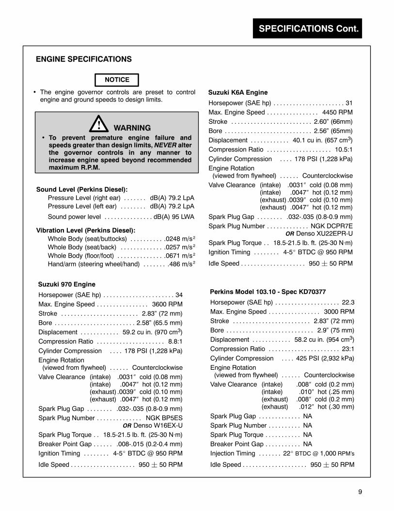
Each engine has a serial number stamped onto the engine block. The Perkins diesel’s serial no. is stamped on ametal plate which is attached to the engine block.
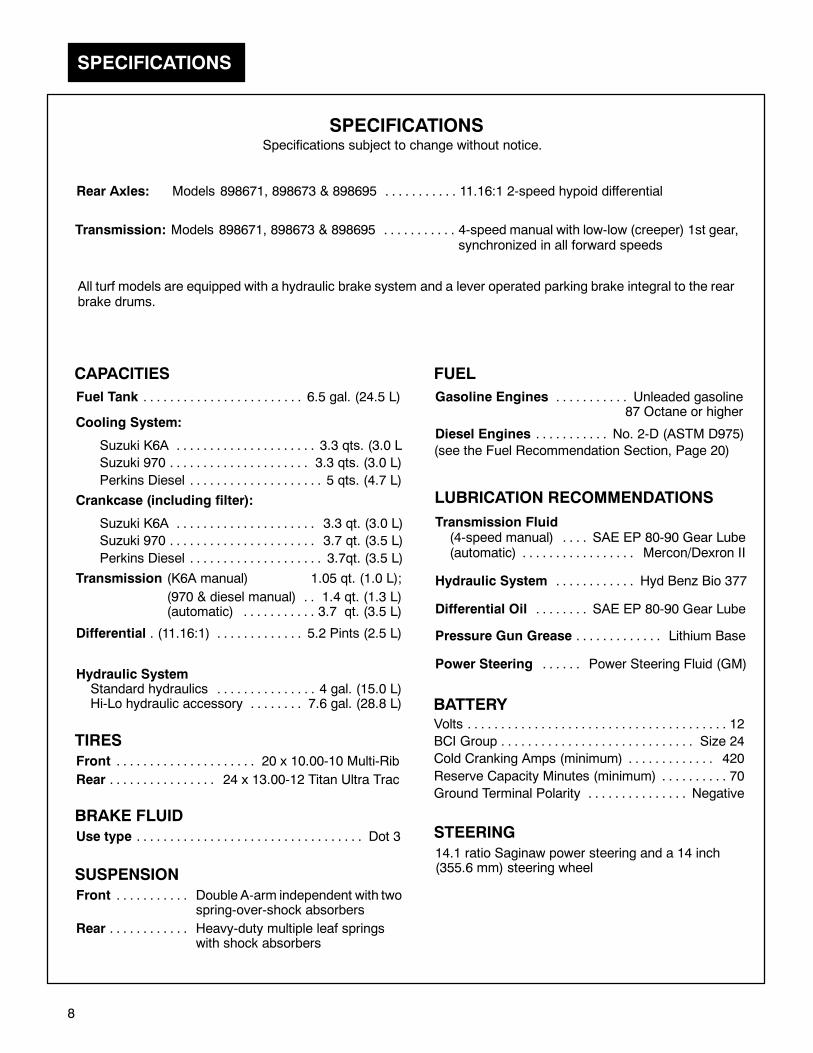
Figure 4Suzuki 970 Engine Serial Number
(As Viewed From the Drivers Side of Vehicle)
Figure 5Perkins Diesel Engine Serial Number
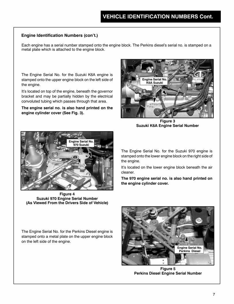
Engine Identification Numbers (con’t.)
The Engine Serial No. for the Suzuki K6A engine is
stamped onto the upper engine block on the left side of
the engine.
Figure 3Suzuki K6A Engine Serial Number
It’s located on top of the engine, beneath the governor
bracket and may be partially hidden by the electrical
convoluted tubing which passes through that area.
The Engine Serial No. for the Suzuki 970 engine is
stamped onto the lower engine block on the right sideof
the engine.
It’s located on the lower engine block beneath the air
cleaner.
The Engine Serial No. for the Perkins Diesel engine is
stamped onto a metal plate on the upper engine block
on the left side of the engine.
Engine Serial No.Perkins Diesel
The engine serial no. is also hand printed on the
engine cylinder cover (See Fig. 3).
The 970 engine serial no. is also hand printed on
the engine cylinder cover.
Engine Serial No.K6A Suzuki
SPECIFICATIONS
8
SPECIFICATIONSSpecifications subject to change without notice.
Rear Axles: Models 898671, 898673 & 898695 11.16:1 2-speed hypoid differential. . . . . . . . . . .
CAPACITIES
Transmission (K6A manual) 1.05 qt. (1.0 L);
(970 & diesel manual) 1.4 qt. (1.3 L). .(automatic) 3.7 qt. (3.5 L). . . . . . . . . . .
Crankcase (including filter):
Suzuki K6A 3.3 qt. (3.0 L). . . . . . . . . . . . . . . . . . . . .
Suzuki 970 3.7 qt. (3.5 L). . . . . . . . . . . . . . . . . . . . . .
Perkins Diesel 3.7qt. (3.5 L). . . . . . . . . . . . . . . . . . . .
Cooling System:
Suzuki K6A 3.3 qts. (3.0 L. . . . . . . . . . . . . . . . . . . . .
Suzuki 970 3.3 qts. (3.0 L). . . . . . . . . . . . . . . . . . . . .
Perkins Diesel 5 qts. (4.7 L). . . . . . . . . . . . . . . . . . . .
Transmission: Models 898671, 898673 & 898695 4-speed manual with low-low (creeper) 1st gear,. . . . . . . . . . .synchronized in all forward speeds
Fuel Tank 6.5 gal. (24.5 L). . . . . . . . . . . . . . . . . . . . . . . .
LUBRICATION RECOMMENDATIONS
Hydraulic System Hyd Benz Bio 377. . . . . . . . . . . .
Transmission Fluid(4-speed manual) SAE EP 80-90 Gear Lube. . . .(automatic) Mercon/Dexron II. . . . . . . . . . . . . . . . .
Hydraulic SystemStandard hydraulics 4 gal. (15.0 L). . . . . . . . . . . . . . .Hi-Lo hydraulic accessory 7.6 gal. (28.8 L). . . . . . . .
All turf models are equipped with a hydraulic brake system and a lever operated parking brake integral to the rearbrake drums.
BRAKE FLUID
Use type Dot 3. . . . . . . . . . . . . . . . . . . . . . . . . . . . . . . . . .
FUEL
Gasoline Engines Unleaded gasoline. . . . . . . . . . .87 Octane or higher
Diesel Engines No. 2-D (ASTM D975). . . . . . . . . . .
(see the Fuel Recommendation Section, Page 20)
Differential (11.16:1) 5.2 Pints (2.5 L). . . . . . . . . . . . . .
Differential Oil SAE EP 80-90 Gear Lube. . . . . . . .
Pressure Gun Grease Lithium Base. . . . . . . . . . . . .
Power Steering Power Steering Fluid (GM). . . . . .
TIRES
Front 20 x 10.00-10 Multi-Rib. . . . . . . . . . . . . . . . . . . . .
Rear 24 x 13.00-12 Titan Ultra Trac. . . . . . . . . . . . . . . .
SUSPENSION
Front Double A-arm independent with two. . . . . . . . . . .spring-over-shock absorbers
Rear Heavy-duty multiple leaf springs. . . . . . . . . . . .with shock absorbers
STEERING
14.1 ratio Saginaw power steering and a 14 inch(355.6 mm) steering wheel
BATTERYVolts 12. . . . . . . . . . . . . . . . . . . . . . . . . . . . . . . . . . . . . . .
BCI Group Size 24. . . . . . . . . . . . . . . . . . . . . . . . . . . . .
Cold Cranking Amps (minimum) 420. . . . . . . . . . . . .
Reserve Capacity Minutes (minimum) 70. . . . . . . . . .
Ground Terminal Polarity Negative. . . . . . . . . . . . . . .
SPECIFICATIONS Cont.
9
ENGINE SPECIFICATIONS
Horsepower (SAE hp) 34. . . . . . . . . . . . . . . . . . . . . .
Max. Engine Speed 3600 RPM. . . . . . . . . . . . . . . .
Stroke 2.83” (72 mm). . . . . . . . . . . . . . . . . . . . . . . .
Bore 2.58” (65.5 mm). . . . . . . . . . . . . . . . . . . . . . . . .
Displacement 59.2 cu in. (970 cm3). . . . . . . . . . . .
Compression Ratio 8.8:1. . . . . . . . . . . . . . . . . . . . .
Cylinder Compression 178 PSI (1,228 kPa). . . .
Engine Rotation(viewed from flywheel) Counterclockwise. . . . . .
Valve Clearance (intake) .0031 cold (0.08 mm)(intake) .0047 hot (0.12 mm)(exhaust) .0039 cold (0.10 mm)(exhaust) .0047 hot (0.12 mm)
Spark Plug Gap .032-.035 (0.8-0.9 mm). . . . . . . .
Spark Plug Number NGK BP5ES. . . . . . . . . . . . . .OR Denso W16EX-U
Spark Plug Torque 18.5-21.5 lb. ft. (25-30 N m). .
Breaker Point Gap .008-.015 (0.2-0.4 mm). . . . . .
Ignition Timing 4-5 BTDC @ 950 RPM. . . . . . . .
Idle Speed 950¦ 50 RPM. . . . . . . . . . . . . . . . . . . .
Suzuki 970 Engine
Horsepower (SAE hp) 22.3. . . . . . . . . . . . . . . . . . . .
Max. Engine Speed 3000 RPM. . . . . . . . . . . . . . . .
Stroke 2.83” (72 mm). . . . . . . . . . . . . . . . . . . . . . . .
Bore 2.9” (75 mm). . . . . . . . . . . . . . . . . . . . . . . . . . .
Displacement 58.2 cu in. (954 cm3). . . . . . . . . . . .
Compression Ratio 23:1. . . . . . . . . . . . . . . . . . . . . .
Cylinder Compression 425 PSI (2,932 kPa). . . .
Engine Rotation(viewed from flywheel) Counterclockwise. . . . . .
Valve Clearance (intake) .008 cold (0.2 mm)(intake) .010 hot (.25 mm)(exhaust) .008 cold (0.2 mm)(exhaust) .012 hot (.30 mm)
Spark Plug Gap NA. . . . . . . . . . . . .
Spark Plug Number NA. . . . . . . . . .
Spark Plug Torque NA. . . . . . . . . . .
Breaker Point Gap NA. . . . . . . . . . .
Injection Timing 22 BTDC @ 1,000 RPM’s. . . . . . .
Idle Speed 950¦ 50 RPM. . . . . . . . . . . . . . . . . . . .
Perkins Model 103.10 - Spec KD70377
• To prevent premature engine failure andspeeds greater than design limits, NEVER alterthe governor controls in any manner toincrease engine speed beyond recommendedmaximum R.P.M.
WARNING!
NOTICE
• The engine governor controls are preset to controlengine and ground speeds to design limits.
Sound Level (Perkins Diesel):
Pressure Level (right ear) dB(A) 79.2 LpA. . . . . . .
Pressure Level (left ear) dB(A) 79.2 LpA. . . . . . . .
Sound power level dB(A) 95 LWA. . . . . . . . . . . . . . .
Vibration Level (Perkins Diesel):
Whole Body (seat/buttocks) .0248 m/s. . . . . . . . . .
Whole Body (seat/back) .0257 m/s. . . . . . . . . . . . .
Whole Body (floor/foot) .0671 m/s. . . . . . . . . . . . . .
Hand/arm (steering wheel/hand) .486 m/s. . . . . . .
2
2
2
2
Horsepower (SAE hp) 31. . . . . . . . . . . . . . . . . . . . . .
Max. Engine Speed 4450 RPM. . . . . . . . . . . . . . . .
Stroke 2.60” (66mm). . . . . . . . . . . . . . . . . . . . . . . . .
Bore 2.56” (65mm). . . . . . . . . . . . . . . . . . . . . . . . . . .
Displacement 40.1 cu in. (657 cm3). . . . . . . . . . . .
Compression Ratio 10.5:1. . . . . . . . . . . . . . . . . . . .
Cylinder Compression 178 PSI (1,228 kPa). . . .
Engine Rotation(viewed from flywheel) Counterclockwise. . . . . .
Valve Clearance (intake) .0031 cold (0.08 mm)(intake) .0047 hot (0.12 mm)(exhaust) .0039 cold (0.10 mm)(exhaust) .0047 hot (0.12 mm)
Spark Plug Gap .032-.035 (0.8-0.9 mm). . . . . . . .
Spark Plug Number NGK DCPR7E. . . . . . . . . . . . .OR Denso XU22EPR-U
Spark Plug Torque 18.5-21.5 lb. ft. (25-30 N m). .
Ignition Timing 4-5 BTDC @ 950 RPM. . . . . . . .
Idle Speed 950¦ 50 RPM. . . . . . . . . . . . . . . . . . . .
Suzuki K6A Engine
CONTROLS
10
The following pages contain informationwhichwill help you becomemore familiar with the dif-ferent gauges and controls used while operating this vehicle.
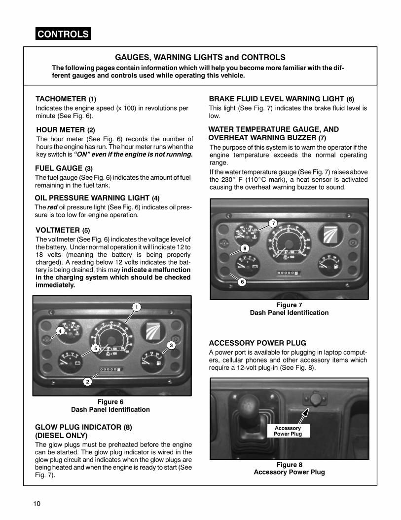
Figure 7Dash Panel Identification
OIL PRESSURE WARNING LIGHT (4)
The red oil pressure light (See Fig. 6) indicates oil pres-sure is too low for engine operation.
WATER TEMPERATURE GAUGE, ANDOVERHEAT WARNING BUZZER (7)
GAUGES, WARNING LIGHTS and CONTROLS
Figure 6Dash Panel Identification
The purpose of this system is to warn the operator if theengine temperature exceeds the normal operatingrange.
VOLTMETER (5)
The voltmeter (See Fig. 6) indicates the voltage level ofthebattery. Under normal operation it will indicate 12 to18 volts (meaning the battery is being properlycharged). A reading below 12 volts indicates the bat-tery is being drained, this may indicate amalfunctionin the charging system which should be checkedimmediately.
TACHOMETER (1)
Indicates the engine speed (x 100) in revolutions perminute (See Fig. 6).
FUEL GAUGE (3)
The fuel gauge (SeeFig. 6) indicates theamount of fuelremaining in the fuel tank.
7
If thewater temperature gauge (SeeFig. 7) raisesabovethe 230 F (110 C mark), a heat sensor is activatedcausing the overheat warning buzzer to sound.
HOUR METER (2)
The hour meter (See Fig. 6) records the number ofhours theenginehas run. Thehourmeter runs when thekey switch is “ON” even if the engine is not running.
BRAKE FLUID LEVEL WARNING LIGHT (6)
This light (See Fig. 7) indicates the brake fluid level islow.
6
Figure 8Accessory Power Plug
ACCESSORY POWER PLUG
A power port is available for plugging in laptop comput-ers, cellular phones and other accessory items whichrequire a 12-volt plug-in (See Fig. 8).
AccessoryPower Plug
3
1
2
4
GLOW PLUG INDICATOR (8)(DIESEL ONLY)
The glow plugs must be preheated before the enginecan be started. The glow plug indicator is wired in theglow plug circuit and indicates when the glow plugs arebeing heated andwhen the engine is ready to start (SeeFig. 7).
5
8
CONTROLS Cont.
11
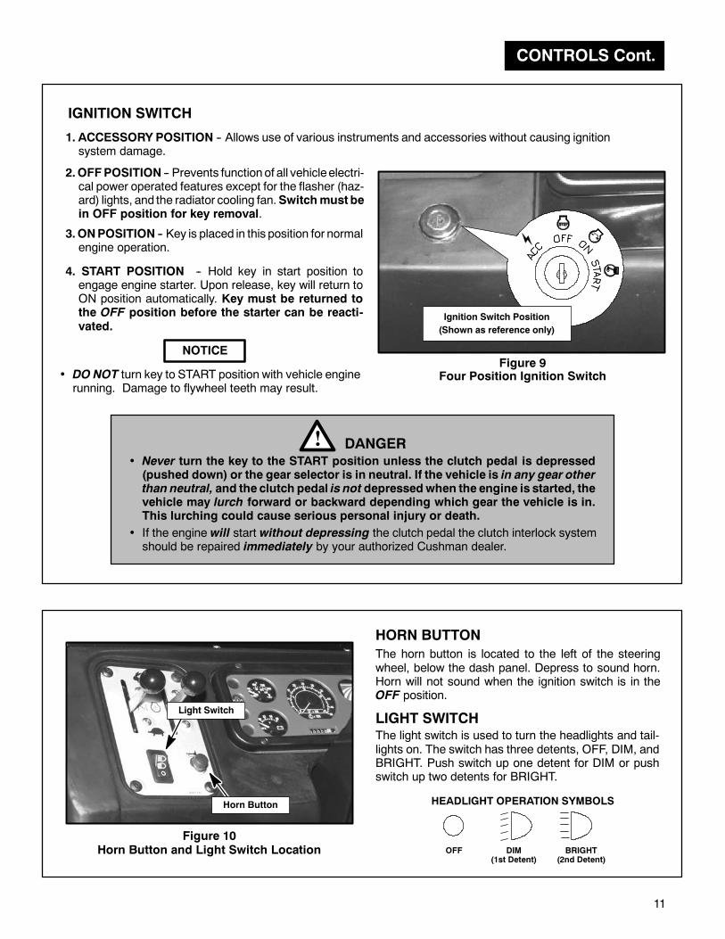
3.ONPOSITION -- Key is placed in this position for normalengine operation.
4. START POSITION -- Hold key in start position toengage engine starter. Upon release, key will return toON position automatically. Key must be returned tothe OFF position before the starter can be reacti-vated.
IGNITION SWITCH
Figure 9Four Position Ignition Switch• DO NOT turn key to START position with vehicle engine
running. Damage to flywheel teeth may result.
NOTICE
1. ACCESSORY POSITION -- Allows use of various instruments and accessories without causing ignitionsystem damage.
2.OFFPOSITION -- Prevents function of all vehicleelectri-cal power operated features except for the flasher (haz-ard) lights, and the radiator cooling fan.Switchmust bein OFF position for key removal.
• Never turn the key to the START position unless the clutch pedal is depressed(pushed down) or the gear selector is in neutral. If the vehicle is in any gear otherthan neutral, and the clutch pedal is not depressedwhen the engine is started, thevehicle may lurch forward or backward depending which gear the vehicle is in.This lurching could cause serious personal injury or death.
DANGER!
Ignition Switch Position
(Shown as reference only)
• If the engine will start without depressing the clutch pedal the clutch interlock systemshould be repaired immediately by your authorized Cushman dealer.
Figure 10Horn Button and Light Switch Location
HORN BUTTON
The horn button is located to the left of the steeringwheel, below the dash panel. Depress to sound horn.Horn will not sound when the ignition switch is in theOFF position.
LIGHT SWITCHThe light switch is used to turn the headlights and tail-lights on. The switch has three detents, OFF, DIM, andBRIGHT. Push switch up one detent for DIM or pushswitch up two detents for BRIGHT.
OFF DIM(1st Detent)
BRIGHT(2nd Detent)
HEADLIGHT OPERATION SYMBOLS
Light Switch
Horn Button

CONTROLS Cont.
12
ChokeKnob
Figure 11Park Brake Lever and Choke Knob
Park BrakeLever
FOOT CONTROL PEDALS
If the engine will start without depressing the clutchpedal:
• DO NOT operate the vehicle. The clutch interlock
system should be repaired immediately by yourauthorized Cushman dealer.
The clutch pedal has to be depressed before shiftinginto any of the gears. The clutch has a Safety Featurecalled a “clutch interlock switch”. This switch pre-vents the starter from operating unless the clutch is dis-
engaged (the clutch pedal is depressed).
CLUTCH PEDAL (Manual Transmission Only)
Clutch Pedal
Figure 12Clutch Pedal Location
The clutch pedal has to be depressed:before starting the vehiclebefore shifting into any of the gears andbefore coming to a complete stop
DANGER!• Neverstart theengineunless theclutch pedal is depressed (pushed down). If thevehicle is inanygearother thanneutral,with theclutch pedalnotdepressed and theengine is started, thevehicle will lurch forward or backward depending which gear the vehicle is in. This lurchingcould cause serious personal injury or death.
The park brake lever is located to the left side of thedrivers seat. To engage the brake, pull up on the leveruntil park brake is applied.
PARKING BRAKE LEVER
To release, while slightly pulling upon thehandle, push thebuttonat theendof the lever andwhile holding thebutton in,lower the lever to it’s original position (See Fig. 11).
• Parking brakes are not automatically applied. Makesure and set the park brake when leaving thevehicle.
The choke is used to assist the starting of a coldengine. Pull up on the choke knob and hold in the fullor partially open position. When the engine haswarmed up and is running smoothly release the chokeknob (the choke knob is spring loaded in theopenposi-tion, it will return to its normal position when released)(See Fig. 11).
CHOKE (Suzuki 970 engines Only)

CONTROLS Cont.
13
Remember, before shifting to any gear you have todepress the clutch pedal before you shift to that particu-lar gear.
Figure 14Shift Pattern (Manual Transmission)
1
2
3
4 R
N
Push pedal down to open throttle (increase speed), release to return throttle to idle position (decrease speed).
Depress the pedal to slow or stop the vehicle.
If the brakes DO NOT stop the vehicle properly, thebrakes must be adjusted or repaired.
SERVICE BRAKE PEDAL
CAUTION!• Improper maintenance of brake system canresult in the operator losing control ofvehicle.
• Loads not properly secured can quickly shiftcausing personal injury or vehicle damage ifthe brakes are applied too hard and fast.
Brake Pedal
Figure 13Foot Control Pedals
AcceleratorPedal
FOOT THROTTLE (ACCELERATOR) PEDAL
The gear selector has an “H” pattern as shown in Figure14. There is also a shift-pattern designmolded into the topof the gear selector handle.
GEAR SELECTOR
Manual Transmission
Figure 15Automatic Transmission Gear Selector
Automatic Transmission
Push in the selector lever button when shifting in or outof “P” Park , into “N” Neutral or when down shifting to“2” Second or “L” Low from “D” Drive.
It is not necessary to use the button when shifting upfrom Low, Second or Drive to Neutral, from Reverse(R) to Neutral or from Neutral to Drive.
Thegear selector has thegear selections listedon the leftside of the shifter handle. Some units may have thegear selections on the right side as shown in Fig. 15.

SERVICE & MAINTENANCE
14
The following maintenance information covers basic engine service only.
For extensive service and repairs, we recommend contacting the authorized Cushman dealer nearest you.
ENGINE MAINTENANCE
Keep your engine clean.
If dirt has accumulated on the engine, it should be washed with a non--flammable solvent or strong detergent.
Proper maintenance will prolong the engine’s life and avoid premature overhaul.
When washing becomes necessary, it can be carried out simultaneously when servicing the vehicle.
In order to maintain reliable service from your engine, a regular check-up and maintenance schedule should befollowed.
ACCESS TO ENGINE
Never remove or install the engine cover while the engine is running. The engine cover is amachinery guard andits removal exposes you to moving parts. Keep hands, hair and clothing away from flywheel, radiator cooling fan,alternator fan, engine belts, pulleys and air intake.
For servicing the engine and related components, the engine cover can be tilted forward or removed.
SERVICE and MAINTENANCE
• When replacement parts are required, use genuine Cushman parts or parts with equivalentcharacteristics including type, strength andmaterial. Failure to do somay result in productmal-function and possible injury to the operator and/or bystanders.
• Never attempt to perform service or maintenance functions on this vehicle if you are
UNTRAINEDorUNAUTHORIZED. Impropermaintenance can cause hazardous conditions. Seeyour authorized CUSHMAN dealer for necessary maintenance and service.
• Always replace any warning decal that becomes hard to read.
• To reduce risk of fire, always keep the engine free of excessive grease.
WARNING!
Think Ahead!Work Safely!
ENGINE BREAK IN
• To prevent premature engine failure andspeeds greater than design limits,NEVER alter the governor controls in anymanner to increaseenginespeedbeyondrecommended maximum R.P.M.
WARNING!The service life of your engine is dependent upon howyour engine is operated during the first 50 hours ofoperation.
ALWAYS: Use care not to overload your engineMaintain engine oil levelMaintain cooling system
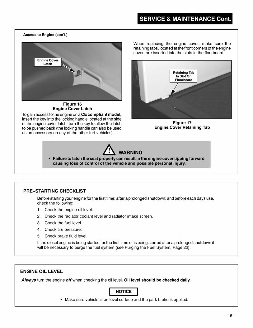
Togain access to theengine, push theengine cover latch to the rear of the unit, tilt cover forward. The latch is locatedat the center rear on top of the engine cover (between the seat cushion(s) and backwall).
SERVICE & MAINTENANCE Cont.
15
Engine CoverLatch
Figure 16Engine Cover Latch
When replacing the engine cover, make sure theretaining tabs, locatedat the front corners of theenginecover, are inserted into the slots in the floorboard.
Figure 17Engine Cover Retaining Tab
• Failure to latch the seat properly can result in the engine cover tipping forwardcausing loss of control of the vehicle and possible personal injury.
WARNING!
Before starting your engine for the first time; after a prolonged shutdown; and before each days use,check the following:
1. Check the engine oil level.
2. Check the radiator coolant level and radiator intake screen.
3. Check the fuel level.
4. Check tire pressure.
5. Check brake fluid level.
If the diesel engine is being started for the first time or is being started after a prolonged shutdown itwill be necessary to purge the fuel system (see Purging the Fuel System, Page 22).
Retaining TabIn Slot OnFloorboard
PRE--STARTING CHECKLIST
Access to Engine (con’t.)
ENGINE OIL LEVEL
Always turn the engine off when checking the oil level. Oil level should be checked daily.
NOTICE
• Make sure vehicle is on level surface and the park brake is applied.
Togain access to theengineonaCEcompliantmodel,insert the key into the locking handle located at the sideof the engine cover latch, turn the key to allow the latchto be pushed back (the locking handle can also be usedas an accessory on any of the other turf vehicles).
SERVICE & MAINTENANCE Cont.
16
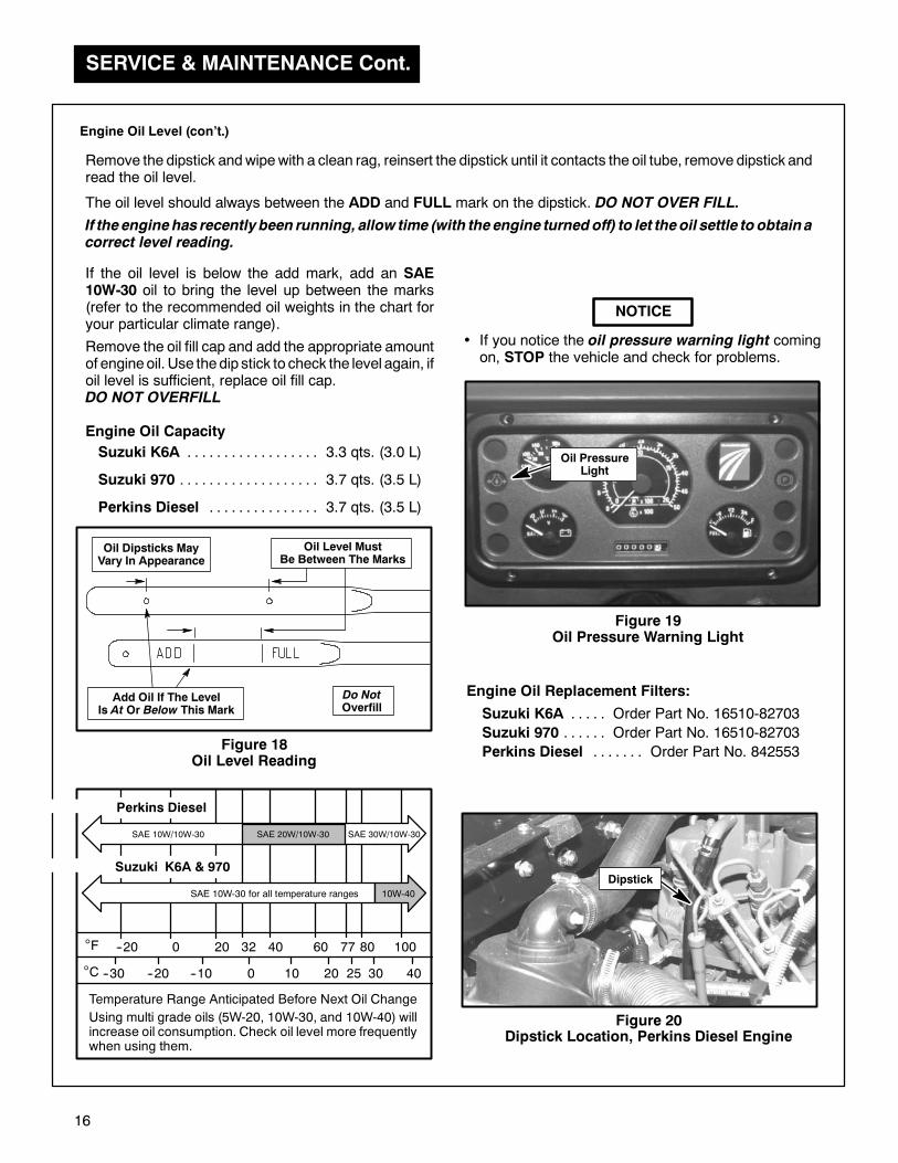
Figure 18Oil Level Reading
Figure 19Oil Pressure Warning Light
NOTICE
• If you notice the oil pressure warning light comingon, STOP the vehicle and check for problems.
Figure 20Dipstick Location, Perkins Diesel Engine
Remove the oil fill cap and add the appropriate amountof engineoil. Use thedip stick to check the level again, ifoil level is sufficient, replace oil fill cap.DO NOT OVERFILL
If the oil level is below the add mark, add an SAE10W-30 oil to bring the level up between the marks(refer to the recommended oil weights in the chart foryour particular climate range).
Oil PressureLight
Engine Oil Capacity
Suzuki K6A 3.3 qts. (3.0 L). . . . . . . . . . . . . . . . . .
Suzuki 970 3.7 qts. (3.5 L). . . . . . . . . . . . . . . . . . .
Perkins Diesel 3.7 qts. (3.5 L). . . . . . . . . . . . . . .
Engine Oil Level (con’t.)
Dipstick
Engine Oil Replacement Filters:
Suzuki K6A Order Part No. 16510-82703. . . . .
Suzuki 970 Order Part No. 16510-82703. . . . . .
Perkins Diesel Order Part No. 842553. . . . . . .
Remove the dipstick andwipewith a clean rag, reinsert the dipstick until it contacts the oil tube, remove dipstick andread the oil level.
The oil level should always between the ADD and FULL mark on the dipstick. DO NOT OVER FILL.
If theenginehas recentlybeen running, allow time (with theengine turnedoff) to let theoil settle to obtainacorrect level reading.
°F
°C
--20 0 20 32 40 60 77 80 100
40302520100--10--20--30
Temperature Range Anticipated Before Next Oil Change
SAE 10W-30 for all temperature ranges
Using multi grade oils (5W-20, 10W-30, and 10W-40) willincrease oil consumption. Check oil level more frequentlywhen using them.
10W-40
SAE 10W/10W-30
Suzuki K6A & 970
Perkins Diesel
SAE 20W/10W-30 SAE 30W/10W-30
Do NotOverfill
Oil Dipsticks MayVary In Appearance
Add Oil If The LevelIs At Or Below This Mark
Oil Level MustBe Between The Marks
SERVICE & MAINTENANCE
17
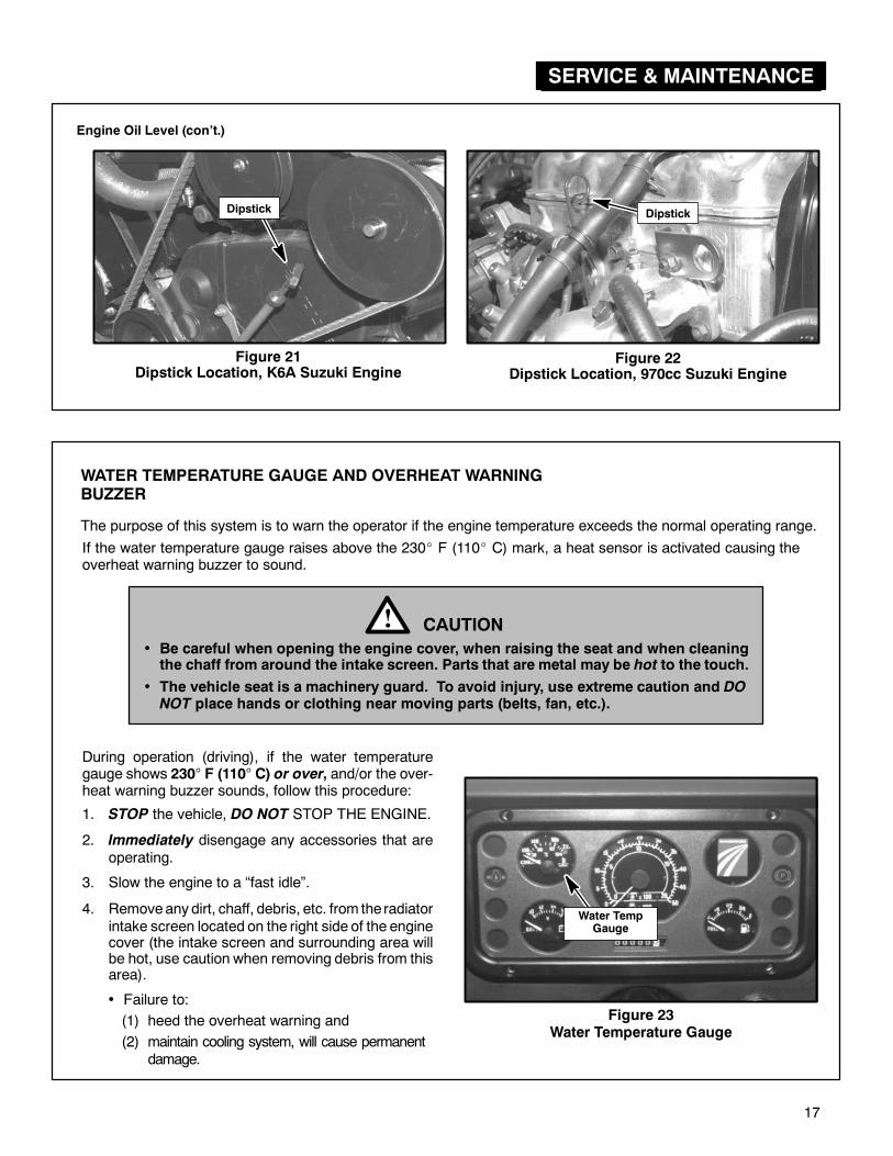
During operation (driving), if the water temperaturegauge shows 230° F (110° C) or over, and/or the over-heat warning buzzer sounds, follow this procedure:
1. STOP the vehicle, DO NOT STOP THE ENGINE.
2. Immediately disengage any accessories that areoperating.
3. Slow the engine to a “fast idle”.
4. Removeany dirt, chaff, debris, etc. from the radiatorintake screen located on the right side of the enginecover (the intake screen and surrounding area willbe hot, use caution when removing debris from thisarea).
Figure 23Water Temperature Gauge
Water TempGauge
CAUTION!• Be careful when opening the engine cover, when raising the seat and when cleaningthe chaff from around the intake screen. Parts that are metal may be hot to the touch.
• The vehicle seat is a machinery guard. To avoid injury, use extreme caution and DONOT place hands or clothing near moving parts (belts, fan, etc.).
• Failure to:
(2) maintain cooling system, will cause permanentdamage.
If the water temperature gauge raises above the 230 F (110 C) mark, a heat sensor is activated causing theoverheat warning buzzer to sound.
(1) heed the overheat warning and
WATER TEMPERATURE GAUGE AND OVERHEAT WARNINGBUZZER
The purpose of this system is to warn the operator if the engine temperature exceeds the normal operating range.
Dipstick
Figure 22Dipstick Location, 970cc Suzuki Engine
Engine Oil Level (con’t.)
Dipstick
Figure 21Dipstick Location, K6A Suzuki Engine

SERVICE & MAINTENANCE Cont.
18
The temperature indicator on the gauge should go down within approximately 30 seconds after the intake screenis cleaned. If the temperature does not go down, STOP THE ENGINE and check the following areas:
WARNING!
• The cooling system is under pressure, if a leak is present, be careful when raising the seator when opening the engine cover. Hot coolant can be sprayed causing personal injury.
• ALWAYS make sure the engine is stopped and cool before removing the radiator cap orbefore performing any service or maintenance on or around the engine area. To preventscalding by hot water, NEVER remove the radiator cap while radiator is hot.
1. Raise vehicle seat and visually check to see if electric radiator fan is operating and check to determine if theremay be a leak in the cooling system (allow ample time for the engine and surrounding area to cool beforeattempting to perform any service or maintenance).
2. Check the radiator fins and screen. If they are dirty, theymust be cleaned. Engines damaged due to over-heating caused by plugged radiatorsWILL NOT be warranted.
3. Check oil engine level.
4. Check radiator and coolant reservoir levels.
Water Temperature Gauge and Overheat Warning Buzzer (con’t.)
To provide proper engine cooling it is important to keep the coolingsystem properly maintained. Part of maintaining the system involvesmaking sure the intake screen, radiator fins and surrounding engineareas remain free of debris.
RADIATOR COOLANT LEVEL
009034880
Fan Warning DecalRadiator Warning Decal
840748
• DO NOT obstruct or cover the intake screen in front of the radiator.Keep the fins and radiator screens clean.
• If the radiator fins or intake screenbecome dirty, air cannot circulatewell enough to cool the engine sufficiently, therefore you risk thechance of the engine overheating. Engines damaged due tooverheating caused by plugged radiators WILL NOT be war-ranted.
WARNING!• The cooling fan is thermostatically controlled and may start at any time, even with theignition key in the OFF position, DO NOT attempt service without first disconnecting thenegative (--) battery cable or without first removing the fan fuse.
• The cooling system is under pressure, if a leak is present, be careful when raising the seator when opening the engine cover. Hot coolant can be sprayed causing personal injury.
The vehicle is equipped with a cooling radiator and an electric cooling fan.
Also refer to page 37 for Dash Panel Bulb Replacement.
SERVICE & MAINTENANCE Cont.
19
1. Check the radiator and coolant hoses for leaks andfaulty connections, repair as necessary.
2. Inspect the engine belts for fraying or cracking andcheck the engine for loose hardware.
• ALWAYS make sure the engine is stoppedand cool before removing the radiator cap.To prevent scalding by hot water, NEVERremove cap while radiator is hot.
WARNING!
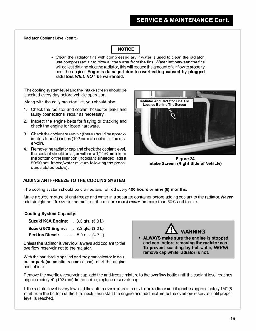
Figure 24Intake Screen (Right Side of Vehicle)
Radiator And Radiator Fins AreLocated Behind The Screen
3. Check the coolant reservoir (there should beapprox-imately four (4) inches (102mm) of coolant in the res-ervoir).
4. Remove the radiator capand check the coolant level,the coolant should be at, or with-in a 1/4” (6mm) fromthebottomof the filler port (if coolant is needed, adda50/50 anti-freeze/water mixture following the proce-dures stated below).
Suzuki K6A Engine: 3.3 qts. (3.0 L).
Suzuki 970 Engine: 3.3 qts. (3.0 L). .
Perkins Diesel: 5.0 qts. (4.7 L). . . . . .
Cooling System Capacity:
Unless the radiator is very low, always add coolant to theoverflow reservoir not to the radiator.
NOTICE
• Clean the radiator fins with compressed air. If water is used to clean the radiator,use compressed air to blow all the water from the fins. Water left between the finswill collect dirt andplug the radiator, thiswill reduce theamount of air flow toproperlycool the engine. Engines damaged due to overheating caused by pluggedradiatorsWILL NOT be warranted.
Radiator Coolant Level (con’t.)
Thecooling system level and the intake screen should bechecked every day before vehicle operation.
Along with the daily pre-start list, you should also:
ADDING ANTI-FREEZE TO THE COOLING SYSTEM
The cooling system should be drained and refilled every 400 hours or nine (9) months.
Make a 50/50 mixture of anti-freeze and water in a separate container before adding coolant to the radiator. Neveradd straight anti-freeze to the radiator, the mixture must never be more than 50% anti-freeze.
With the park brake applied and the gear selector in neu-tral or park (automatic transmissions), start the engineand let idle.
Remove the overflow reservoir cap, add the anti-freeze mixture to the overflow bottle until the coolant level reachesapproximately 4” (102 mm) in the bottle, replace reservoir cap.
If the radiator level is very low, add theanti-freezemixture directly to the radiator until it reaches approximately 1/4” (6mm) from the bottom of the filler neck, then start the engine and add mixture to the overflow reservoir until properlevel is reached.
SERVICE & MAINTENANCE Cont.
20
GASOLINE CONTAINING ALCOHOL
We DO NOT recommend the use of ALCOHOL bearing fuels in any of our products. The use of these fuels maycreate a potential safety hazard.
FUEL LEVEL
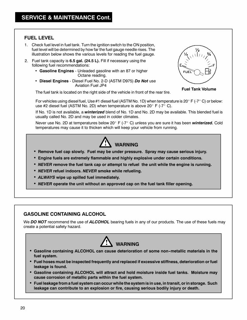
1. Check fuel level in fuel tank. Turn the ignition switch to the ONposition,fuel level will be determined by how far the fuel gauge needle rises. Theillustration below shows the various levels for reading the fuel gauge.
Fuel Tank Volume
2. Fuel tank capacity is 6.5 gal. (24.5 L). Fill if necessary using thefollowing fuel recommendations:
• Remove fuel cap slowly. Fuel may be under pressure. Spray may cause serious injury.
• Engine fuels are extremely flammable and highly explosive under certain conditions.
• NEVER remove the fuel tank cap or attempt to refuel the unit while the engine is running.
• NEVER refuel indoors. NEVER smoke while refueling.
• ALWAYS wipe up spilled fuel immediately.
• NEVER operate the unit without an approved cap on the fuel tank filler opening.
WARNING!
• Gasoline Engines - Unleaded gasoline with an 87 or higherOctane reading.
• Gasoline containing ALCOHOL can cause deterioration of some non--metallic materials in thefuel system.
• Fuel hosesmust be inspected frequently and replaced if excessive stiffness, deterioration or fuel
leakage is found.
• Gasoline containing ALCOHOL will attract and hold moisture inside fuel tanks. Moisture maycause corrosion of metallic parts within the fuel system.
• Fuel leakage froma fuel systemcanoccurwhile thesystem is in use, in transit, or instorage. Suchleakage can contribute to an explosion or fire, causing serious bodily injury or death.
WARNING!
The fuel tank is located on the right side of the vehicle in front of the rear tire.
• Diesel Engines - Diesel Fuel No. 2-D (ASTM D975) Do Not useAviation Fuel JP4
For vehicles using diesel fuel, Use#1 diesel fuel (ASTMNo. 1D)when temperature is 20 F (-7 C) or below:use #2 diesel fuel (ASTM No. 2D) when temperature is above 20 F (-7 C).
If No. 1D is not available, a winterized blend of No. 1D and No. 2D may be available. This blended fuel isusually called No. 2D and may be used in colder climates.
Never use No. 2D at temperatures below 20 F (-7 C) unless you are sure it has been winterized. Coldtemperatures may cause it to thicken which will keep your vehicle from running.
SERVICE & MAINTENANCE Cont.
21
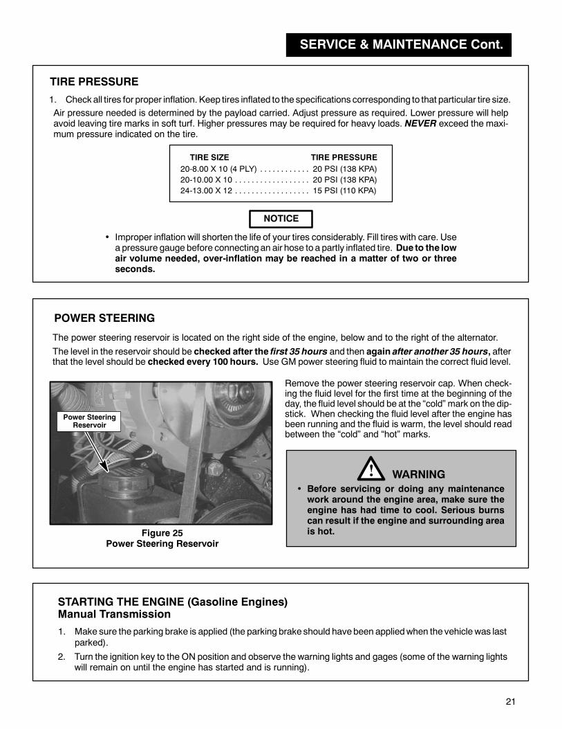
Figure 25Power Steering Reservoir
1. Check all tires for proper inflation. Keep tires inflated to the specifications corresponding to that particular tire size.
20-8.00 X 10 (4 PLY) 20 PSI (138 KPA). . . . . . . . . . . .
20-10.00 X 10 20 PSI (138 KPA). . . . . . . . . . . . . . . . . .
24-13.00 X 12 15 PSI (110 KPA). . . . . . . . . . . . . . . . . .
TIRE SIZE TIRE PRESSURE
TIRE PRESSURE
NOTICE
• Improper inflation will shorten the life of your tires considerably. Fill tires with care. Usea pressure gauge before connecting an air hose to a partly inflated tire. Due to the lowair volume needed, over-inflation may be reached in a matter of two or threeseconds.
POWER STEERING
The level in the reservoir should be checked after the first 35 hours and then again after another 35 hours, afterthat the level should be checked every 100 hours. Use GM power steering fluid to maintain the correct fluid level.
WARNING!• Before servicing or doing any maintenancework around the engine area, make sure theengine has had time to cool. Serious burnscan result if the engine and surrounding areais hot.
Power SteeringReservoir
Remove the power steering reservoir cap. When check-ing the fluid level for the first time at the beginning of theday, the fluid level should be at the “cold” mark on the dip-stick. When checking the fluid level after the engine hasbeen running and the fluid is warm, the level should readbetween the “cold” and “hot” marks.
The power steering reservoir is located on the right side of the engine, below and to the right of the alternator.
STARTING THE ENGINE (Gasoline Engines)Manual Transmission
1. Make sure the parking brake is applied (the parking brake should havebeen appliedwhen the vehicle was lastparked).
Air pressure needed is determined by the payload carried. Adjust pressure as required. Lower pressure will helpavoid leaving tire marks in soft turf. Higher pressures may be required for heavy loads. NEVER exceed the maxi-mum pressure indicated on the tire.
2. Turn the ignition key to the ON position and observe the warning lights and gages (some of the warning lightswill remain on until the engine has started and is running).
SERVICE & MAINTENANCE Cont.
22
3. Move the gear selector to “NEUTRAL”.
4. Push clutch pedal down (starter will not operate unless clutch pedal is pushed down). The clutch inter-lock switch prevents the starter fromoperating unless the clutch is disengaged (the clutchpedal isdepressed).
• If the enginedoes not start after operating starter for 10 seconds, stop the starter. Wait for 30 seconds, thentry to start the engine again.
• The starter motor should never be run for more than 30 seconds.
6. Allowengine towarm-upbefore driving the vehicle (always idle andwarm-up the engine for at least oneminute).
Starting the Engine con’t.
If the enginewill startwithout depressing the clutch pedalDONOT operate the vehicle. The clutch interlocksystem should be repaired immediately by your authorized Cushman dealer.
5. Turn and hold ignition key in the START position to engage engine starter, release key when engine starts(upon release, the key will automatically return to the ON position).
• Never turn the key to the START position unless the clutch pedal is depressed(pushed down) or the gear selector is in neutral. If the vehicle is in any gear otherthan neutral, and the clutch pedal is not depressedwhen the engine is started, thevehicle may lurch forward or backward depending which gear the vehicle is in.This lurching could cause serious personal injury or death.
DANGER!
STARTING THE ENGINE (Gasoline Engines)
1. Apply the park brake (the parking brake should have been applied when the vehicle was last parked).
Automatic Transmission
2. Make sure the gear selector is in Park “P” (enginewill not start if gear selector is in “R”, “D”, “2”, or “L”).
• If the enginedoes not start after operating starter for 10 seconds, stop the starter. Wait for 30 seconds, thentry to start the engine again.
• The starter motor should never be run for more than 30 seconds.
5. Allow engine to warm-up before driving the vehicle (always allow at least one minute for the engine towarm-up).
3. Turn the ignition key to the ON position and observe the warning lights and gages (some of the warning lightswill remain on until the engine has started and is running).
If the engine will start when the gear selector is in “R”, “D”, “2”, or “L” DO NOT operate the vehicle. Thevehicle should be repaired immediately by your authorized Cushman dealer.
4. Turn and hold ignition key in the START position to engage engine starter, release key when engine starts(upon release, the key will automatically return to the ON position).
• Never turn the key to the START position unless the gear selector is in “Park” orneutral. If the vehicle is in any gear other than Park or neutral, and the engine isstarted, the vehicle may lurch forward or backward depending which gear thevehicle is in. This lurching could cause serious personal injury or death.
DANGER!
SERVICE & MAINTENANCE Cont.
23
STARTING THE ENGINE (Diesel Engines)
Manual Transmission
1. Apply the park brake (the parking brake should have been applied when the vehicle was last parked).
2. Move the gear selector to “NEUTRAL”.
Whenstarting anew diesel engine for the first time, or after prolonged storage, or if the fuel tank is allowed torun dry, the fuel systemmust be purged before attempting to start the engine (refer to Purging the Diesel FuelSystem, Page 22 of this manual).
The diesel engine uses glow plugs to pre-heat the combustion chamber and makes cold engines start easier.
When starting the vehicle for the first time during the day or when the engine has cooled, you will need topre-heat the glow plugs in order to start the engine.
If the engine has been running and is still hot, it is not necessary to pre-heat the glow plugs before starting theengine.
3. Push clutch pedal down (starter will not operate unless clutch pedal is pushed down). The clutch inter-lock switch prevents the starter fromoperating unless the clutch is disengaged (the clutch pedal is depressed).
If the enginewill startwithout depressing the clutch pedalDONOT operate the vehicle. The clutch interlocksystem should be repaired immediately by your authorized Cushman dealer.
Figure 26Pre-Heat Indicator Light (Diesel Models Only)
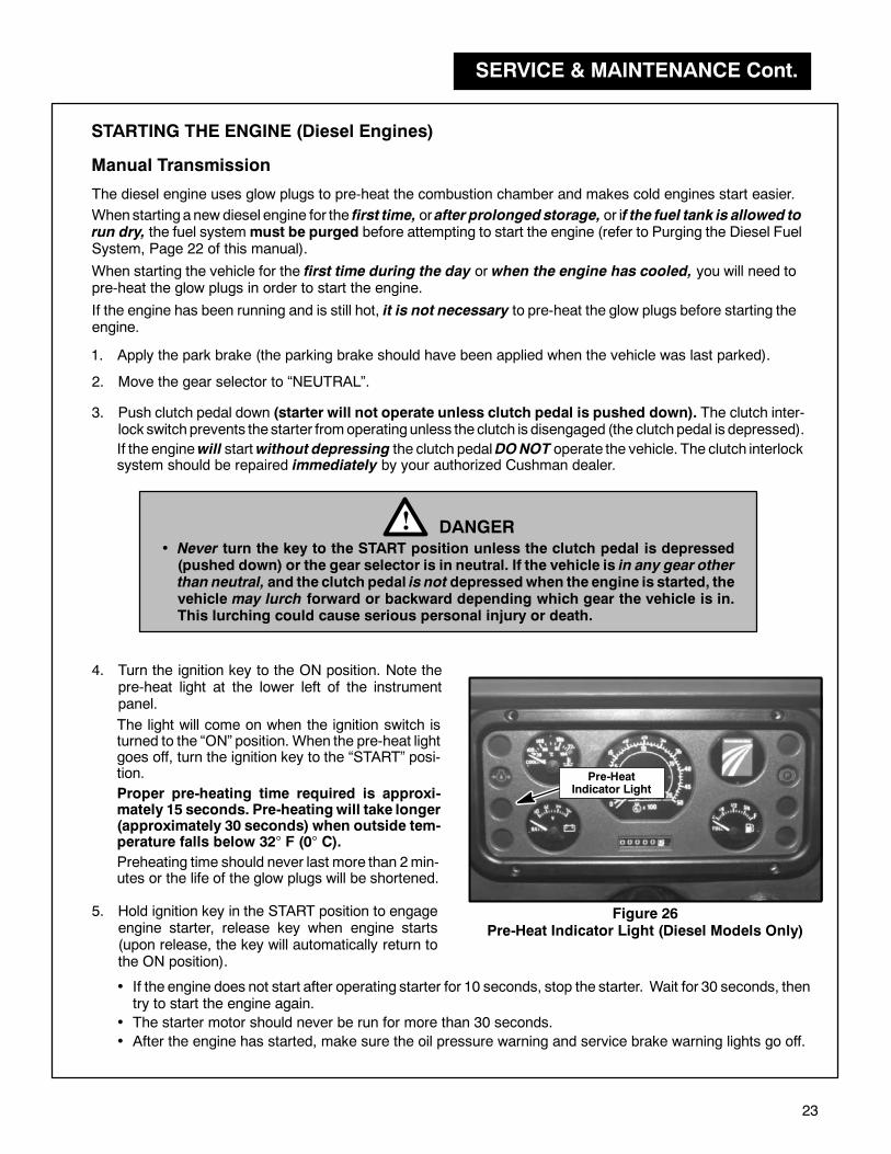
4. Turn the ignition key to the ON position. Note thepre-heat light at the lower left of the instrumentpanel.
The light will come on when the ignition switch isturned to the “ON” position. When the pre-heat lightgoes off, turn the ignition key to the “START” posi-tion. Pre-Heat
Indicator LightProper pre-heating time required is approxi-mately 15 seconds. Pre-heatingwill take longer(approximately 30 seconds) when outside tem-perature falls below 32° F (0° C).
Preheating time should never last more than 2min-utes or the life of the glow plugs will be shortened.
• Never turn the key to the START position unless the clutch pedal is depressed(pushed down) or the gear selector is in neutral. If the vehicle is in any gear otherthan neutral, and the clutch pedal is not depressedwhen the engine is started, thevehicle may lurch forward or backward depending which gear the vehicle is in.This lurching could cause serious personal injury or death.
DANGER!
• If the engine does not start after operating starter for 10 seconds, stop the starter. Wait for 30 seconds, thentry to start the engine again.
• The starter motor should never be run for more than 30 seconds.
• After the engine has started, make sure the oil pressure warning and service brake warning lights go off.
5. Hold ignition key in the START position to engageengine starter, release key when engine starts(upon release, the key will automatically return tothe ON position).
SERVICE & MAINTENANCE Cont.
24
6. Allow engine to warm-up before driving the vehicle (always idle and warm-up the engine for at least oneminute)
Starting the Diesel Engine con’t.
NOTICE
• DO NOT use ether or starting fluid with diesel engines.Severe engine damage will occur.
Check for abnormal noises such as knocking and excessive vibration
Knocking sounds will not be heard during normal operation.
Starting under sub-freezing conditions:
•Make sure correct weight engine oil is used.
•Make sure the battery is fully charged.
•Pre-heat glow plugs for the correct length of time.
•Make sure cooling system is tested safe for the ambient temperature.
Knocking sounds will be heard while the engine is cold, during quick acceleration and while idling.
Confirm the exhaust smoke is seen as follows:
While engine is cold: White smoke
When engine is warm and during normal operation: Almost smokeless
When engine is heavily loaded: Some black smoke
PURGING THE DIESEL FUEL SYSTEM
The fuel system must be purged when:
• Starting a new diesel engine for the first time
• After prolonged storage
• The fuel tank is allowed to run dry
• The fuel filter and/or fuel lines have been loosened, removed or replaced
Purge the fuel system using one of the procedures as follows:
PURGING FUEL SYSTEM USING A JUMPER WIRE
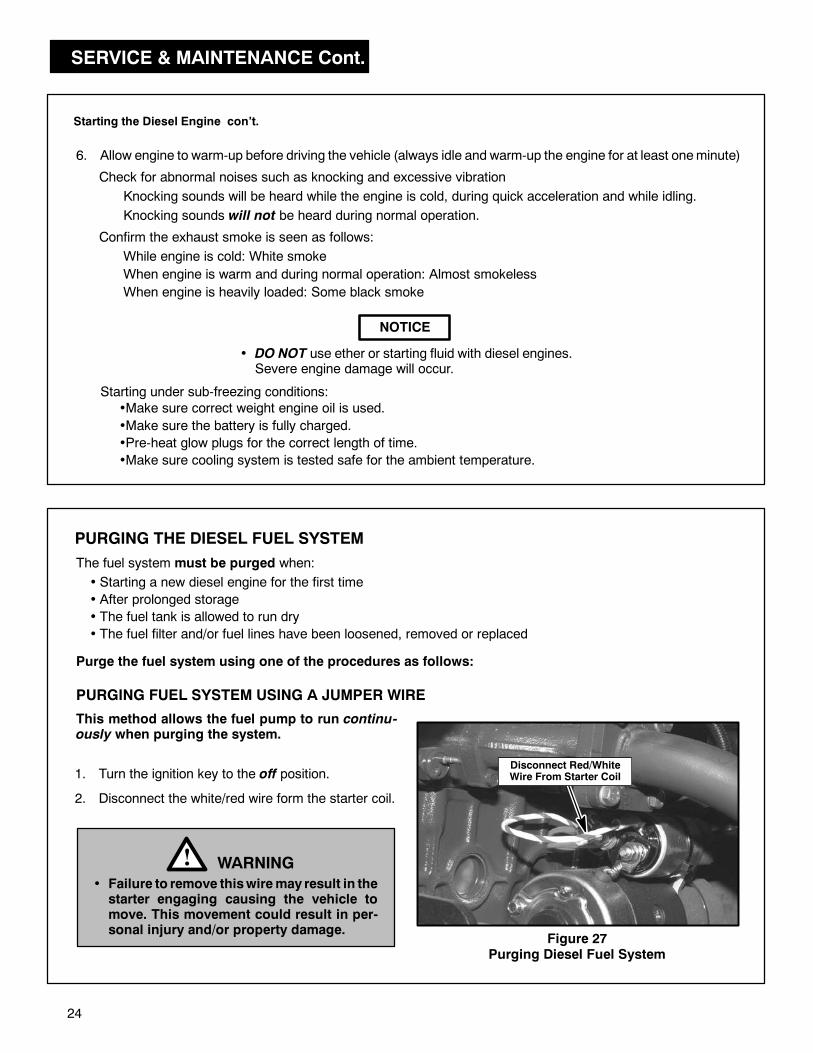
Disconnect Red/WhiteWire From Starter Coil
Figure 27Purging Diesel Fuel System
WARNING!• Failure to remove thiswiremay result in thestarter engaging causing the vehicle tomove. This movement could result in per-sonal injury and/or property damage.
1. Turn the ignition key to the off position.
2. Disconnect the white/red wire form the starter coil.
This method allows the fuel pump to run continu-ously when purging the system.
SERVICE & MAINTENANCE Cont.
25
Purging the Diesel Fuel System (con’t.)
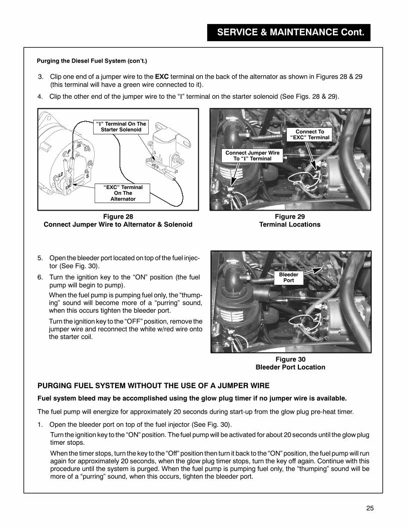
Figure 28Connect Jumper Wire to Alternator & Solenoid
3. Clip one end of a jumper wire to the EXC terminal on the back of the alternator as shown in Figures 28 & 29(this terminal will have a green wire connected to it).
Figure 29Terminal Locations
4. Clip the other end of the jumper wire to the “I” terminal on the starter solenoid (See Figs. 28 & 29).
Connect To“EXC” Terminal
“I” Terminal On TheStarter Solenoid
“EXC” TerminalOn The
Alternator
Connect Jumper WireTo “I” Terminal
5. Open thebleeder port located on top of the fuel injec-tor (See Fig. 30).
Figure 30Bleeder Port Location
BleederPort
6. Turn the ignition key to the “ON” position (the fuelpump will begin to pump).
When the fuel pump is pumping fuel only, the “thump-ing” sound will become more of a “purring” sound,when this occurs tighten the bleeder port.
Turn the ignition key to the “OFF” position, remove thejumper wire and reconnect the white w/red wire ontothe starter coil.
PURGING FUEL SYSTEM WITHOUT THE USE OF A JUMPER WIRE
Fuel system bleed may be accomplished using the glow plug timer if no jumper wire is available.
The fuel pump will energize for approximately 20 seconds during start-up from the glow plug pre-heat timer.
Turn the ignition key to the “ON” position. The fuel pumpwill be activated for about 20 seconds until the glowplugtimer stops.
1. Open the bleeder port on top of the fuel injector (See Fig. 30).
When the timer stops, turn the key to the “Off” position then turn it back to the “ON” position, the fuel pumpwill runagain for approximately 20 seconds, when the glow plug timer stops, turn the key off again. Continue with thisprocedure until the system is purged. When the fuel pump is pumping fuel only, the “thumping” sound will bemore of a “purring” sound, when this occurs, tighten the bleeder port.
SERVICE & MAINTENANCE
26
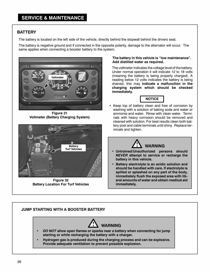
BATTERY
The battery in this vehicle is “low maintenance”.Add distilled water as required.
Figure 32Battery Location For Turf Vehicles
NOTICE
• Keep top of battery clean and free of corrosion bywashing with a solution of baking soda and water orammonia and water. Rinse with clean water. Termi-nals with heavy corrosion should be removed andcleaned with solution. For best results clean both bat-tery post and cable terminals until shiny. Replace ter-minals and tighten.
• Untrained/Unauthorized persons shouldNEVER attempt to service or recharge thebattery in this vehicle.
• Battery electrolyte is an acidic solution andshould be handled with care. If electrolyte isspilled or splashed on any part of the body,immediately flush the exposed area with lib-eral amounts ofwater andobtainmedical aidimmediately.
WARNING!
JUMP STARTING WITH A BOOSTER BATTERY
• DO NOT allow open flames or sparks near a battery when connecting for jumpstarting or while recharging the battery with a charger.
• Hydrogen gas is produced during the charging process and can be explosive.Provide adequate ventilation to prevent possible explosion.
WARNING!
The battery is located on the left side of the vehicle, directly behind the stopwall behind the drivers seat.
Figure 31Voltmeter (Battery Charging System)
The voltmeter indicates the voltage level of the battery.Under normal operation it will indicate 12 to 18 volts(meaning the battery is being properly charged). Areading below 12 volts indicates the battery is beingdrained, this may indicate a malfunction in thecharging system which should be checkedimmediately.
Voltmeter
The battery is negative ground and if connected in the opposite polarity, damage to the alternator will occur. Thesame applies when connecting a booster battery to the system.
BatteryTurf Vehicles
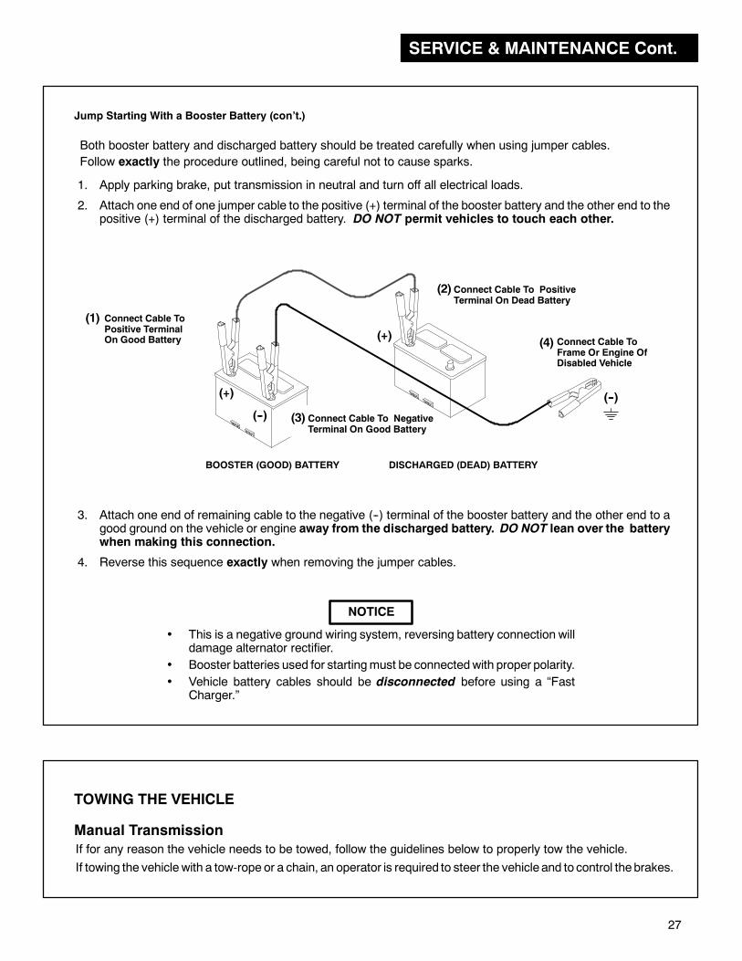
SERVICE & MAINTENANCE Cont.
27
• This is a negative ground wiring system, reversing battery connection willdamage alternator rectifier.
• Booster batteries used for startingmust be connectedwith proper polarity.
• Vehicle battery cables should be disconnected before using a “FastCharger.”
NOTICE
BOOSTER (GOOD) BATTERY DISCHARGED (DEAD) BATTERY
(+)
(--)
(+)
Connect Cable ToPositive TerminalOn Good Battery
(--)
(1)
Connect Cable To NegativeTerminal On Good Battery
(3)
Connect Cable To PositiveTerminal On Dead Battery
(2)
Connect Cable ToFrame Or Engine OfDisabled Vehicle
(4)
Jump Starting With a Booster Battery (con’t.)
1. Apply parking brake, put transmission in neutral and turn off all electrical loads.
2. Attach one end of one jumper cable to the positive (+) terminal of the booster battery and the other end to thepositive (+) terminal of the discharged battery. DO NOT permit vehicles to touch each other.
Both booster battery and discharged battery should be treated carefully when using jumper cables.
Follow exactly the procedure outlined, being careful not to cause sparks.
3. Attach one end of remaining cable to the negative (--) terminal of the booster battery and the other end to agood ground on the vehicle or engine away from the discharged battery. DO NOT lean over the batterywhen making this connection.
4. Reverse this sequence exactly when removing the jumper cables.
TOWING THE VEHICLE
Manual Transmission
If for any reason the vehicle needs to be towed, follow the guidelines below to properly tow the vehicle.
If towing the vehicle with a tow-rope or a chain, an operator is required to steer the vehicle and to control the brakes.
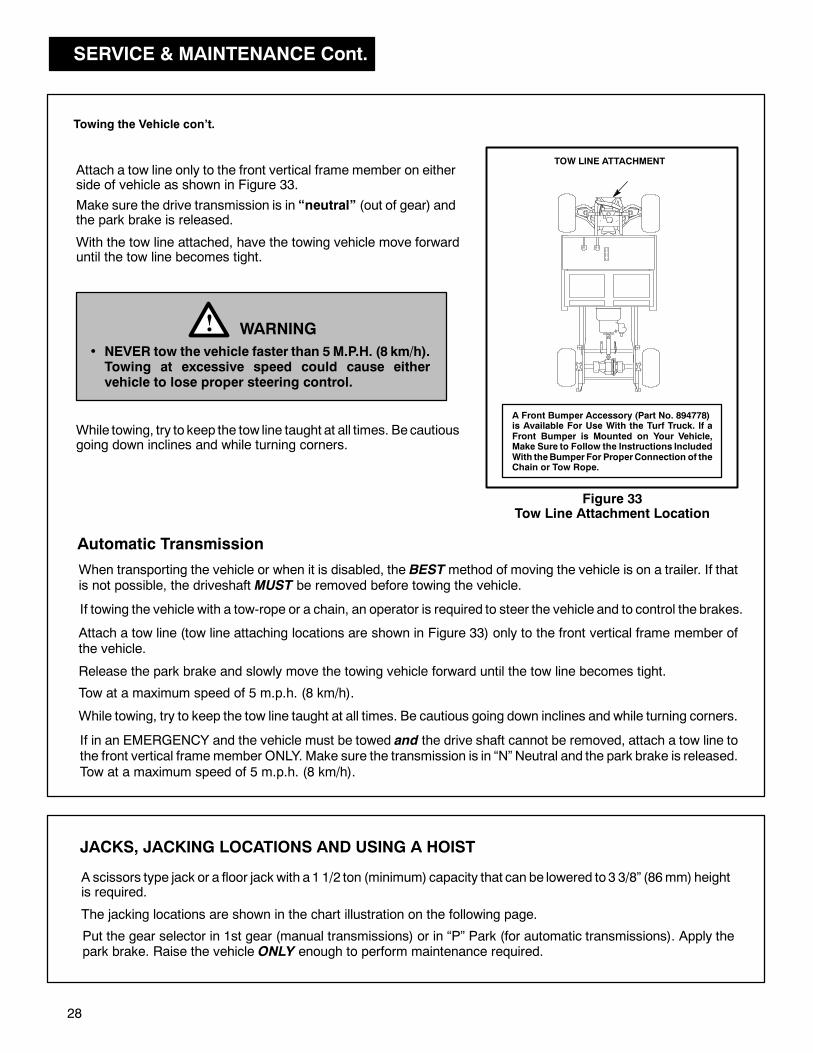
SERVICE & MAINTENANCE Cont.
28
Towing the Vehicle con’t.
Attach a tow line only to the front vertical frame member on eitherside of vehicle as shown in Figure 33.
Make sure the drive transmission is in “neutral” (out of gear) andthe park brake is released.
WARNING!• NEVER tow the vehicle faster than 5M.P.H. (8 km/h).Towing at excessive speed could cause eithervehicle to lose proper steering control.
Figure 33Tow Line Attachment Location
TOW LINE ATTACHMENT
While towing, try to keep the tow line taught at all times. Be cautiousgoing down inclines and while turning corners.
With the tow line attached, have the towing vehicle move forwarduntil the tow line becomes tight.
JACKS, JACKING LOCATIONS AND USING A HOIST
A scissors type jack or a floor jack with a1 1/2 ton (minimum) capacity that can be lowered to 3 3/8” (86mm) heightis required.
The jacking locations are shown in the chart illustration on the following page.
Put the gear selector in 1st gear (manual transmissions) or in “P” Park (for automatic transmissions). Apply thepark brake. Raise the vehicle ONLY enough to perform maintenance required.
A Front Bumper Accessory (Part No. 894778)is Available For Use With the Turf Truck. If aFront Bumper is Mounted on Your Vehicle,Make Sure to Follow the Instructions IncludedWith theBumperFor ProperConnection of theChain or Tow Rope.
Automatic Transmission
When transporting the vehicle or when it is disabled, the BESTmethod of moving the vehicle is on a trailer. If thatis not possible, the driveshaft MUST be removed before towing the vehicle.
If in an EMERGENCY and the vehicle must be towed and the drive shaft cannot be removed, attach a tow line tothe front vertical framemember ONLY. Make sure the transmission is in “N” Neutral and the park brake is released.Tow at a maximum speed of 5 m.p.h. (8 km/h).
Tow at a maximum speed of 5 m.p.h. (8 km/h).
Attach a tow line (tow line attaching locations are shown in Figure 33) only to the front vertical frame member ofthe vehicle.
Release the park brake and slowly move the towing vehicle forward until the tow line becomes tight.
If towing the vehicle with a tow-rope or a chain, an operator is required to steer the vehicle and to control the brakes.
While towing, try to keep the tow line taught at all times. Be cautious going down inclines and while turning corners.

SERVICE & MAINTENANCE Cont.
29
Make sure to block the tirediagonally oppositeof the sidewhich is being raised.
Raise the opposite side of the vehicle enough to allow the fronttire to clear the ground. Place supports under the frame andlower the jack to allow the vehicle to rest on the jack stands.
NOTICE
• When using a hoist to raise the vehicle, use thesame procedure for supporting the frame andblocking the tires as you would when using ajack.
Figure 35Jacking Locations
• DO NOT rely solely on hydraulic or mechanicaljacks for support. Use appropriate jack stands orequivalent for supporting the vehicle. If using ahoist, raise vehicle to appropriateheight and sup-port using jack stands or equivalent support.
• Never place feet, hands or any part of your bodyunder the vehicle when raising it with a hoist.
WARNING!
• To prevent damage to the vehicle or attachedaccessory, NEVER use a hoist to raise onlyone corner of the vehicle. ALWAYS raiseBOTH front or rear corners equally.
Jacks, Jacking Locations and Using a Hoist (con’t.)
Jack the vehicle to the appropriate height and place jackstands or equivalent support beneath the frame near thejack. Lower the jack and allow the vehicle to rest on the jackstands.
Place a jack in the appropriate location (See Fig. 35) andplaceablock behind (or in front) of the tire diagonallyoppo-site the side which is being raised (See Fig. 34).
NOTICE
• Raise the vehicle only enough to perform themaintenancerequired.
If Using Jack Here
Block Tire Here
If Using
Jack Here
Example:
Block Tire Here
The illustration shows the frame without the bodyin order to show the jacking locationsmoreclearly.
- Jacking Location
Figure 34Blocking Tires

SERVICE & MAINTENANCE Cont.
30
TIRE REMOVALFront & Rear
1. Remove the wheel retaining nuts (See Fig 36) andremove tire and wheel assembly from hub.
2. Install the tire and wheel by reversing the abovesequence. Make sure valve stem (See Fig 36) islocated toward the outside.
3. Tighten wheel retaining nuts to 70 to 100 ft. lbs.
(95 to 140 N·m) torque.
Figure 36
Wheel Retaining Nuts and Valve Stem
• DO NOT rely solely on hydraulic or mechanical jacks for support. Useappropriate jack stands or equivalent for supporting the vehicle. Neverplace feet, handsor anypart of yourbodyunder thevehiclewhen raising it.
WARNING!
With the vehicle on a flat level surface (if possible), putthe gear selector in first gear and apply the park brake.
Place a block in front of (or behind) the tire diagonallyopposite the side which is being raised (Refer to the“Jacks, Jacking Locations and Using a Hoist” sec-tion, Pages 26-27 in this manual).
Raise the vehicle only enough to perform the mainte-nance required.
WheelRetaining Nuts
ValveStem

SERVICE & MAINTENANCE
31
Figure 37Air Cleaner Assembly
AirCleaner
SERVICING THE VEHICLE
AIR CLEANER ELEMENT
This is a large capacity dry type air cleaner with a replace-able element.
We recommend the filter element be replaced beforeengine performance is effected. This may occur at 250hoursof service in very dirty operating conditionsor at500hours in normal operating conditions.
We DO NOT recommend cleaning the filter elementbecause of the possibility of damaging the element.
Check theelement for damage, pin holes, etc. by placingalight source such as a flashlight inside.
Clean dust from inside of housing with damp cloth, makingsure dust does NOT enter air intake.
Check all gaskets to be sure they are NOT damaged orloose.
Position the cover so that the collector is pointing down. Clamp cover into position with collector pointing down.
Checking and Installing the Element
To remove the air cleaner element release the latchessecuring the cover to the air cleaner assembly. Removethe filter element.
Replace the element if it is damaged or is excessivelyclogged with dirt and/or debris.
Tilt the engine cover forward and locate theair cleaner onthe right rear of the engine (See Fig. 37).
Figure 38Air Cleaner Element and Dust Cover(Shown Removed From the Housing)
A dirty, clogged or damaged air filter will cause theengine to start hard as well as run rough andsluggish. Don’t forgetto check the air cleaner element if the engine does not run smoothly and other problems cannot be found.
• The dust collector empties automatically when properly installed with collector down.
• DONOT use bent or dented air cleaner assemblies.
• DO NOT use bent or damaged air cleaner element.
Insert element in housing open end first.
WARNING!• Before servicing or doing any maintenancework around the engine area, make sure theengine has had time to cool. Serious burns canresult if the engine or surrounding area is hot.
Air Cleaner Complete Part No. 892679. . . . . . .
Air Cleaner Element Part No. 840352. . . . . . . .
Alternator
Element
Dust Cover
Dust Collector

SERVICE & MAINTENANCE Cont.
32
Front CowlRelease Lever
Figure 41Release Lever For Front Cowl
To open the front cowl, locate the release lever at theupper left corner near the left side headlight.
FRONT COWL ACCESS
The front cowl opens to gain access to the fuse panel,the horn, the master cylinder reservoir as well as vari-ous access panels which when removed, allowaccess to wiring for the dash panel, shifting lever link-age and the upper part of the front suspension.
Pull the lever to the right to release the front cowl latchand at the same time pull up on the front cowl.
Open the cowl allowing it to rest against the rops struc-ture (if equipped) or the steering wheel.
The front cowl will not “spring up” when the releaselever is pulled. The cowl will have to be raised whenthe latch is released.
Access Panel InCenter Of Floorboard
Figure 40Access Panel on Floorboard
ACCESS PANELS
There are two access panels located under the front hood and one located in the middle of the floorboard.
Remove the screws securing the panel to the fire wall to gain access to the shifter linkage and some of the electricalwiring for the instrument panel.
Figure 39Access Panels Under Front Cowl
Remove the screws securing the panel to the bottom of the front cowl to gain access to the front suspension.
Remove the screws securing the panel to the floorboard. This will give you access to the throttle cable, linkage, elec-trical wire harness, as well as the brake lines which run to the master cylinder.
It will be necessary to remove the accelerator pedal in order to completely remove the center floorboardpanel.
AccessPanels
Access PanelRemoved
Pull LeverTo ReleaseCowl Latch
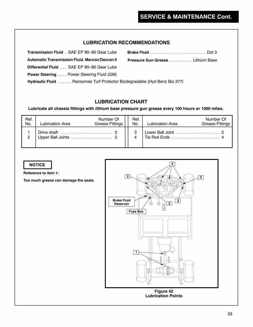
SERVICE & MAINTENANCE Cont.
33
NOTICE
Reference to item 1:
Too much grease can damage the seals.
Ref. Number OfNo. Lubrication Area Grease Fittings
LUBRICATION CHART
Ref. Number OfNo. Lubrication Area Grease Fittings
Lubricate all chassis fittings with lithium base pressure gun grease every 100 hours or 1000 miles.
1 Drive shaft 2. . . . . . . . . . . . . . . . . . . . . . . . .2 Upper Ball Joints 2. . . . . . . . . . . . . . . . . . . .
3 Lower Ball Joint 2. . . . . . . . . . . . . . . . . . . . .4 Tie Rod Ends 4. . . . . . . . . . . . . . . . . . . . . . .
Transmission Fluid SAE EP 80--90 Gear Lube.
Automatic Transmission Fluid. Mercon/Dexron II
Differential Fluid SAE EP 80--90 Gear Lube. . .
Power Steering Power Steering Fluid (GM). . . .
Brake Fluid Dot 3. . . . . . . . . . . . . . . . . . . . . . . . . . .
LUBRICATION RECOMMENDATIONS
Pressure Gun Grease Lithium Base. . . . . . . . . . .
Hydraulic Fluid Ransomes Turf Protector Biodegradable (Hyd Benz Bio 377). . . . . .
2 2
4
Brake FluidReservoir
Fuse Box
33
1
Figure 42Lubrication Points
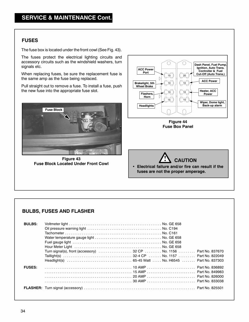
SERVICE & MAINTENANCE Cont.
34
Figure 43Fuse Block Located Under Front Cowl
The fuse box is located under the front cowl (See Fig. 43).
The fuses protect the electrical lighting circuits andaccessory circuits such as the windshield washers, turnsignals etc.
When replacing fuses, be sure the replacement fuse isthe same amp as the fuse being replaced.
Pull straight out to remove a fuse. To install a fuse, pushthe new fuse into the appropriate fuse slot.
FUSES
Fuse Block
Figure 44Fuse Box Panel
CAUTION!• Electrical failure and/or fire can result if thefuses are not the proper amperage.
Voltmeter light No. GE 658. . . . . . . . . . . . . . . . . . . . . . . . . . . . . . . . . . . . . . . . . . . . . . . . . .
Oil pressure warning light No. C194. . . . . . . . . . . . . . . . . . . . . . . . . . . . . . . . . . . . . . . .
Tachometer No. C161. . . . . . . . . . . . . . . . . . . . . . . . . . . . . . . . . . . . . . . . . . . . . . . . . . . .
Water temperature gauge light No. GE 658. . . . . . . . . . . . . . . . . . . . . . . . . . . . . . . . . . . .
Fuel gauge light No. GE 658. . . . . . . . . . . . . . . . . . . . . . . . . . . . . . . . . . . . . . . . . . . . . . . .
Hour Meter Light No. GE 658. . . . . . . . . . . . . . . . . . . . . . . . . . . . . . . . . . . . . . . . . . . . . . .
Turn signal(s), front (accessory) 32 CP No. 1156 Part No. 837670. . . . . . . . . . . . . . . . . . . . . . . . . . . . . . . . . . . .
Taillight(s) 32-4 CP No. 1157 Part No. 822049. . . . . . . . . . . . . . . . . . . . . . . . . . . . . . . . . . . . . . . . . . . . . . . . . . . . .
Headlight(s) 65-45 Watt No. H6545 Part No. 837303. . . . . . . . . . . . . . . . . . . . . . . . . . . . . . . . . . . . . . . . . . . . . . .
10 AMP Part No. 836892. . . . . . . . . . . . . . . . . . . . . . . . . . . . . . . . . . . . . . . . . . . . . . . . . . . . . . . . . . . . . . . . . . . . . . . . .
15 AMP Part No. 849983. . . . . . . . . . . . . . . . . . . . . . . . . . . . . . . . . . . . . . . . . . . . . . . . . . . . . . . . . . . . . . . . . . . . . . . . .
20 AMP Part No. 826000. . . . . . . . . . . . . . . . . . . . . . . . . . . . . . . . . . . . . . . . . . . . . . . . . . . . . . . . . . . . . . . . . . . . . . . . .
30 AMP Part No. 833038. . . . . . . . . . . . . . . . . . . . . . . . . . . . . . . . . . . . . . . . . . . . . . . . . . . . . . . . . . . . . . . . . . . . . . . . .
Turn signal (accessory) Part No. 825501. . . . . . . . . . . . . . . . . . . . . . . . . . . . . . . . . . . . . . . . . . . . . . . . . . . . . . . . . . . .
BULBS:
FUSES:
FLASHER:
BULBS, FUSES AND FLASHER
20
15 10
15
10
10
ACC PowerPort
Brakelight, 5thWheel Brake
Flashers,Horn
10
10
Wiper, Dome light,Back-up alarm
ACC Power
Heater, ACCPower
Dash Panel, Fuel Pump,Ignition, Auto Trans.Controller & Fuel
Cut-Off (Auto Trans.)
Headlights

SERVICE & MAINTENANCE Cont.
35
Check engine oil level
Check cooling system coolant level
Clean radiator intake screen
Check water separator, drain as required(diesel only)
Check fuel level
Check engine for loose parts, damage and leaks
Check exhaust color (diesel only)
Check for engine noise; vibration
Check tire pressure
Change engine oil filter (Perkins)
Check valve clearance(to be done by authorized dealer)
Check engine idle speed
Check power steering fluid
Change fuel filter
Lubricate chassis (see lube chart)
Maintenance Operation Daily
Every75 Hrs
or 2 monthsFirst50 Hrs
Every100 Hrs
or 3 months
Check governor oil level (Suzuki engines)
Check differential oil level
Check transmission fluid level
Check hydraulic tank fluid level
Check brake fluid (BF)
Check brake adjustment
Check clutch adjustment
Change engine oil and filter (Suzuki only)
Change differential oil After first100 hrs.
*
*
First35 Hrs
Change engine oil (Perkins Diesel)
*
MAINTENANCE GUIDE
The followingmaintenance charts have been compiled as a general guideline for service intervals, based on hours
of operation. Refer to the Engine Owner’s Manual for further service and maintenance schedules and intervals.
Depending on operating conditions, the engine oil and engine filter may need more frequent replacement.
If coolant level is low add a 50/50 mixture of water and anti-freeze, NEVER add straight anti-freeze to the coolant system*
OIL FILTER: FUEL FILTER:Suzuki K6A - Part No. 16510-82703
Perkins Diesel - Part No. 842553
Suzuki K6A - Part No. 15410-50F00
Perkins Diesel - Part No. 2208175
HYDRAULIC FLUID (Biodegradable):2 1/2 gal. (9.5 L) - Part No. 65363
5 gal. (19 L) - Part No. 65352
55 gal. (208 L) - Part No. 65354Suzuki 970 - Part No. 16510-82703
Suzuki 970 - Part No. 15410-50F00
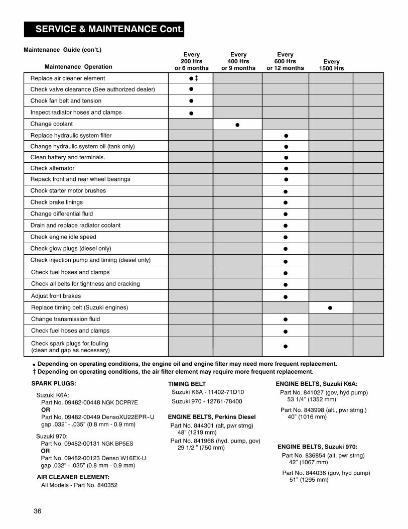
SERVICE & MAINTENANCE Cont.
36
TIMING BELT
ENGINE BELTS, Perkins Diesel
Part No. 844301 (alt, pwr strng)48” (1219 mm)
Suzuki K6A - 11402-71D10
Suzuki 970 - 12761-78400
Part No. 841966 (hyd. pump, gov)29 1/2 ” (750 mm)
Replace air cleaner element
Check valve clearance (See authorized dealer)
Check fan belt and tension
Inspect radiator hoses and clamps
Change coolant
Replace hydraulic system filter
Change hydraulic system oil (tank only)
Clean battery and terminals.
Repack front and rear wheel bearings
Change differential fluid
Drain and replace radiator coolant
Check engine idle speed
Check glow plugs (diesel only)
Check injection pump and timing (diesel only)
Maintenance OperationEvery
1500 Hrs
Check fuel hoses and clamps
Check all belts for tightness and cracking
Adjust front brakes
Replace timing belt (Suzuki engines)
Check starter motor brushes
Check brake linings
Maintenance Guide (con’t.)
Depending on operating conditions, the engine oil and engine filter may need more frequent replacement.*
Every200 Hrs
or 6 months
Every400 Hrs
or 9 months
Every600 Hrs
or 12 months
Check alternator
Change transmission fluid
Check fuel hoses and clamps
Check spark plugs for fouling(clean and gap as necessary)
AIR CLEANER ELEMENT:
SPARK PLUGS:
All Models - Part No. 840352
Depending on operating conditions, the air filter element may require more frequent replacement.
ENGINE BELTS, Suzuki 970:
Part No. 836854 (alt, pwr strng)42” (1067 mm)
Part No. 844036 (gov, hyd pump)51” (1295 mm)
Suzuki 970:
Part No. 09482-00131 NGK BP5ES
OR
Part No. 09482-00123 Denso W16EX-U
gap .032” - .035” (0.8 mm - 0.9 mm)
Suzuki K6A:
Part No. 09482-00448 NGK DCPR7E
OR
Part No. 09482-00449 DensoXU22EPR--U
gap .032” - .035” (0.8 mm - 0.9 mm)
ENGINE BELTS, Suzuki K6A:
Part No. 841027 (gov, hyd pump)53 1/4” (1352 mm)
Part No. 843998 (alt., pwr strng.)40” (1016 mm)
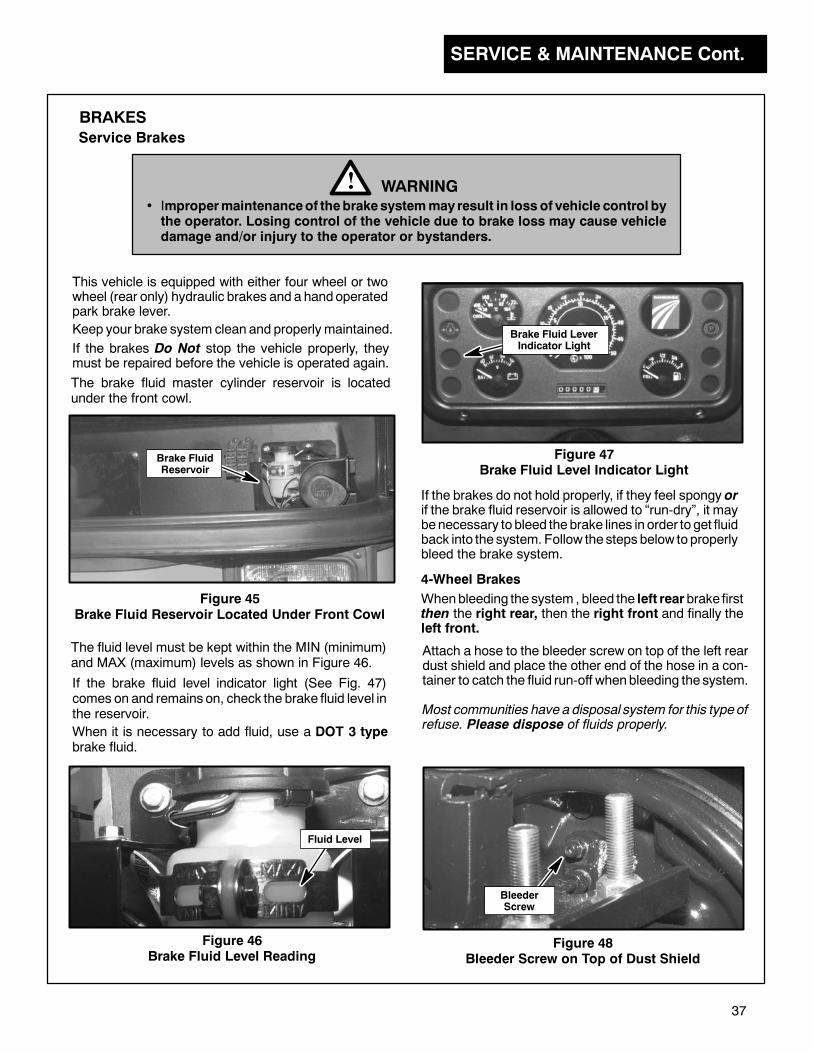
SERVICE & MAINTENANCE Cont.
37
If the brakes do not hold properly, if they feel spongy orif the brake fluid reservoir is allowed to “run-dry”, it maybenecessary to bleed thebrake lines in order to get fluidback into the system. Follow the steps below to properlybleed the brake system.
Fluid Level
BRAKES
This vehicle is equipped with either four wheel or twowheel (rear only) hydraulic brakes and a handoperatedpark brake lever.
Service Brakes
WARNING!• Impropermaintenanceof thebrakesystemmay result in loss of vehicle control bythe operator. Losing control of the vehicle due to brake loss may cause vehicledamage and/or injury to the operator or bystanders.
Keep your brake system clean and properly maintained. Brake Fluid LeverIndicator Light
Figure 45Brake Fluid Reservoir Located Under Front Cowl
The brake fluid master cylinder reservoir is locatedunder the front cowl.
If the brake fluid level indicator light (See Fig. 47)comes on and remains on, check the brake fluid level inthe reservoir.
The fluid level must be kept within the MIN (minimum)and MAX (maximum) levels as shown in Figure 46.
Figure 47Brake Fluid Level Indicator Light
Figure 46Brake Fluid Level Reading
When it is necessary to add fluid, use a DOT 3 typebrake fluid.
If the brakes Do Not stop the vehicle properly, theymust be repaired before the vehicle is operated again.
4-Wheel Brakes
Whenbleeding the system , bleed the left rearbrake firstthen the right rear, then the right front and finally theleft front.
Attach a hose to the bleeder screw on top of the left reardust shield and place the other end of the hose in a con-tainer to catch the fluid run-off whenbleeding the system.
Brake FluidReservoir
BleederScrew
Figure 48Bleeder Screw on Top of Dust Shield
Most communities have a disposal system for this typeofrefuse. Please dispose of fluids properly.
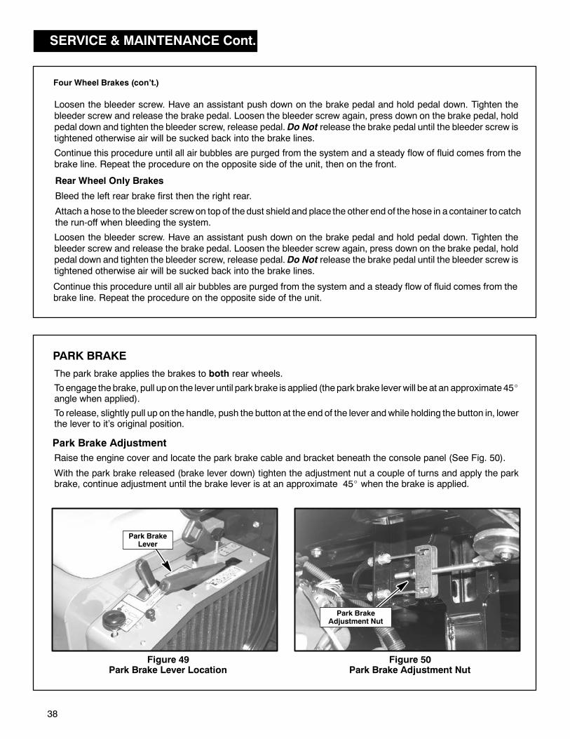
SERVICE & MAINTENANCE Cont.
38
Park BrakeLever
Park BrakeAdjustment Nut
Loosen the bleeder screw. Have an assistant push down on the brake pedal and hold pedal down. Tighten thebleeder screw and release the brake pedal. Loosen the bleeder screw again, press down on the brake pedal, holdpedal down and tighten the bleeder screw, release pedal. Do Not release the brake pedal until the bleeder screw istightened otherwise air will be sucked back into the brake lines.
Continue this procedure until all air bubbles are purged from the system and a steady flow of fluid comes from thebrake line. Repeat the procedure on the opposite side of the unit, then on the front.
Rear Wheel Only Brakes
Bleed the left rear brake first then the right rear.
Attach a hose to the bleeder screwon topof thedust shield and place the other end of the hose in a container to catchthe run-off when bleeding the system.
Continue this procedure until all air bubbles are purged from the system and a steady flow of fluid comes from thebrake line. Repeat the procedure on the opposite side of the unit.
Four Wheel Brakes (con’t.)
PARK BRAKE
Figure 49Park Brake Lever Location
To release, slightly pull up on the handle, push the button at the end of the lever andwhile holding the button in, lowerthe lever to it’s original position.
Toengage thebrake, pull up on the lever until park brake is applied (thepark brake leverwill be at an approximate 45angle when applied).
The park brake applies the brakes to both rear wheels.
Park Brake Adjustment
Raise the engine cover and locate the park brake cable and bracket beneath the console panel (See Fig. 50).
With the park brake released (brake lever down) tighten the adjustment nut a couple of turns and apply the parkbrake, continue adjustment until the brake lever is at an approximate 45 when the brake is applied.
Figure 50Park Brake Adjustment Nut
Loosen the bleeder screw. Have an assistant push down on the brake pedal and hold pedal down. Tighten thebleeder screw and release the brake pedal. Loosen the bleeder screw again, press down on the brake pedal, holdpedal down and tighten the bleeder screw, release pedal. Do Not release the brake pedal until the bleeder screw istightened otherwise air will be sucked back into the brake lines.
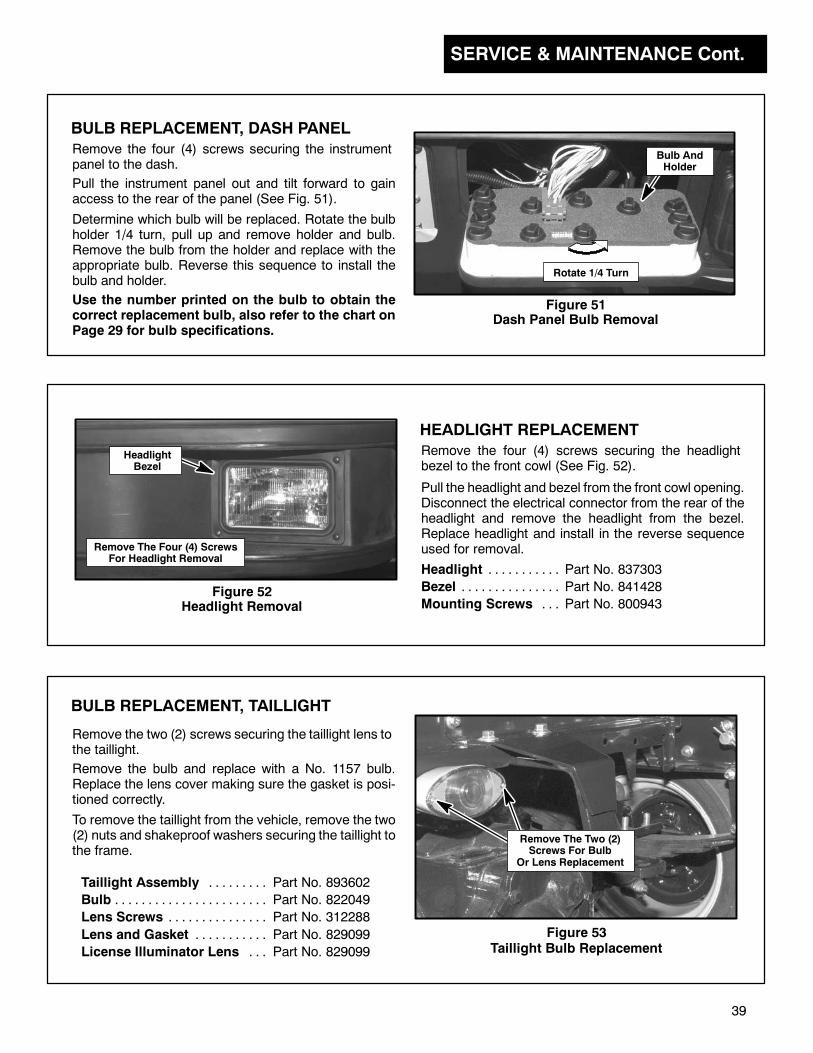
SERVICE & MAINTENANCE Cont.
39
HEADLIGHT REPLACEMENT
Remove the four (4) screws securing the headlightbezel to the front cowl (See Fig. 52).
Pull the headlight and bezel from the front cowl opening.Disconnect the electrical connector from the rear of theheadlight and remove the headlight from the bezel.Replace headlight and install in the reverse sequenceused for removal.Remove The Four (4) Screws
For Headlight Removal
HeadlightBezel
Figure 52Headlight Removal
BULB REPLACEMENT, DASH PANEL
Rotate 1/4 Turn
Remove the four (4) screws securing the instrumentpanel to the dash.
Pull the instrument panel out and tilt forward to gainaccess to the rear of the panel (See Fig. 51).
Determine which bulb will be replaced. Rotate the bulbholder 1/4 turn, pull up and remove holder and bulb.Remove the bulb from the holder and replace with theappropriate bulb. Reverse this sequence to install thebulb and holder.
Figure 51Dash Panel Bulb Removal
Bulb AndHolder
Use the number printed on the bulb to obtain thecorrect replacement bulb, also refer to the chart onPage 29 for bulb specifications.
Headlight Part No. 837303. . . . . . . . . . .
Bezel Part No. 841428. . . . . . . . . . . . . . .
Mounting Screws Part No. 800943. . .
Figure 53Taillight Bulb Replacement
Remove The Two (2)Screws For Bulb
Or Lens Replacement
BULB REPLACEMENT, TAILLIGHT
Remove the two (2) screws securing the taillight lens tothe taillight.
Remove the bulb and replace with a No. 1157 bulb.Replace the lens cover making sure the gasket is posi-tioned correctly.
Taillight Assembly Part No. 893602. . . . . . . . .
Bulb Part No. 822049. . . . . . . . . . . . . . . . . . . . . . .
Lens Screws Part No. 312288. . . . . . . . . . . . . . .
Lens and Gasket Part No. 829099. . . . . . . . . . .
License Illuminator Lens Part No. 829099. . .
To remove the taillight from the vehicle, remove the two(2) nuts and shakeproof washers securing the taillight tothe frame.
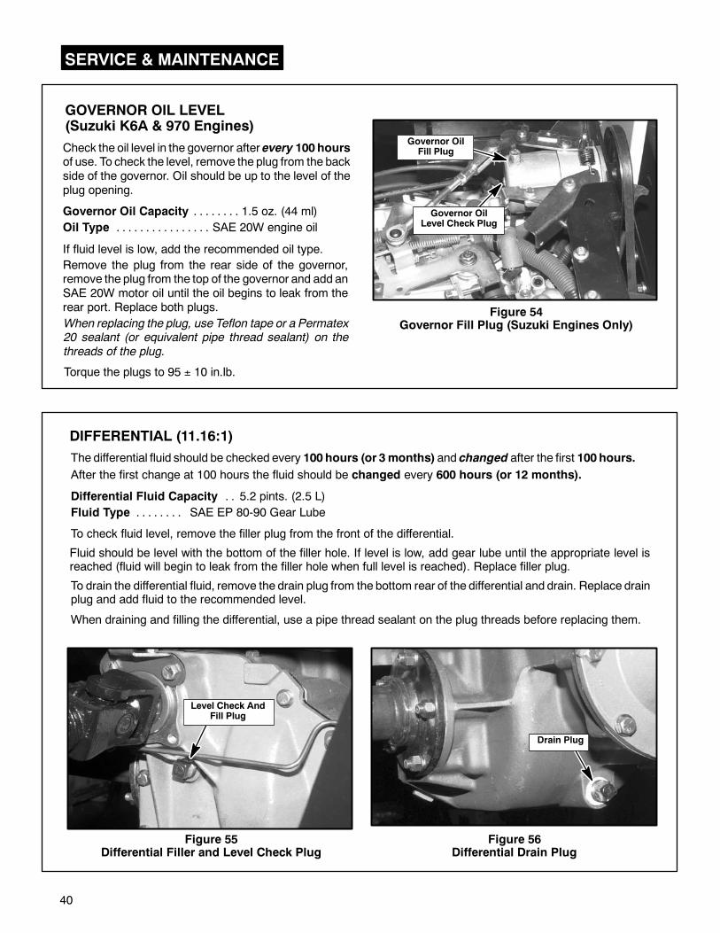
SERVICE & MAINTENANCE
40
GOVERNOR OIL LEVEL(Suzuki K6A & 970 Engines)
Check the oil level in the governor after every 100 hoursof use. To check the level, remove the plug from the backside of the governor. Oil should be up to the level of theplug opening.
Governor Oil Capacity 1.5 oz. (44 ml). . . . . . . .
Oil Type SAE 20W engine oil. . . . . . . . . . . . . . . .
If fluid level is low, add the recommended oil type.
Remove the plug from the rear side of the governor,remove the plug from the top of the governor and add anSAE 20W motor oil until the oil begins to leak from therear port. Replace both plugs. Figure 54
Governor Fill Plug (Suzuki Engines Only)
Governor OilLevel Check Plug
When replacing the plug, use Teflon tape or a Permatex20 sealant (or equivalent pipe thread sealant) on the
threads of the plug.
Torque the plugs to 95 ± 10 in.lb.
DIFFERENTIAL (11.16:1)
Differential Fluid Capacity 5.2 pints. (2.5 L). .
Fluid Type SAE EP 80-90 Gear Lube. . . . . . . .
To check fluid level, remove the filler plug from the front of the differential.
To drain the differential fluid, remove the drain plug from the bottom rear of the differential and drain. Replace drainplug and add fluid to the recommended level.
The differential fluid should be checked every 100 hours (or 3months) and changed after the first 100 hours.
Fluid should be level with the bottom of the filler hole. If level is low, add gear lube until the appropriate level isreached (fluid will begin to leak from the filler hole when full level is reached). Replace filler plug.
After the first change at 100 hours the fluid should be changed every 600 hours (or 12 months).
Figure 55Differential Filler and Level Check Plug
Level Check AndFill Plug
Figure 56Differential Drain Plug
Drain Plug
When draining and filling the differential, use a pipe thread sealant on the plug threads before replacing them.
Governor OilFill Plug
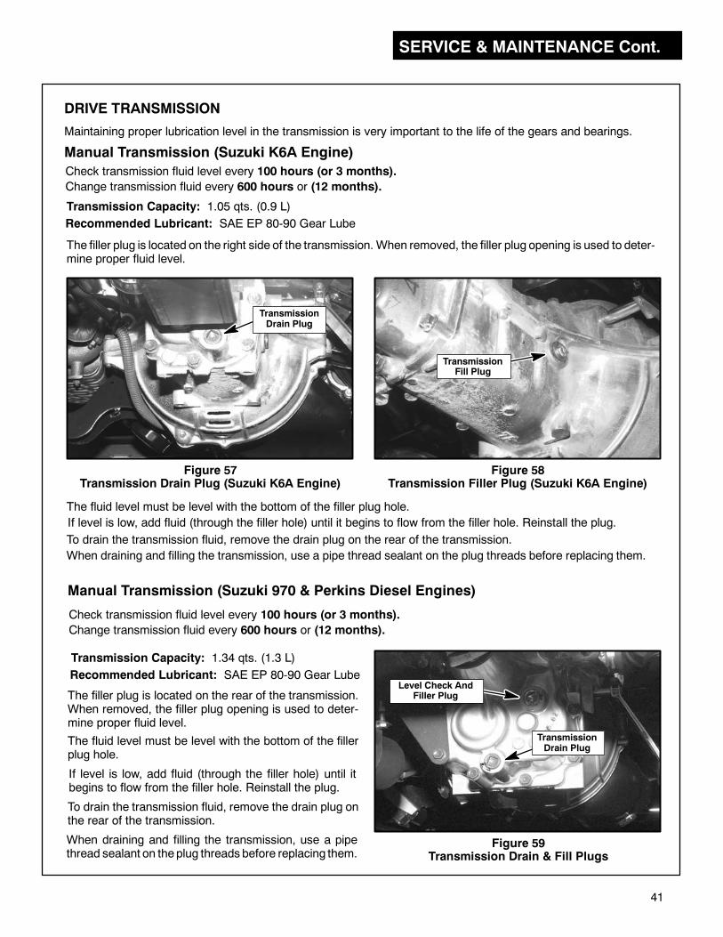
SERVICE & MAINTENANCE Cont.
41
DRIVE TRANSMISSION
Maintaining proper lubrication level in the transmission is very important to the life of the gears and bearings.
Check transmission fluid level every 100 hours (or 3 months).
Change transmission fluid every 600 hours or (12 months).
Transmission Capacity: 1.05 qts. (0.9 L)
Recommended Lubricant: SAE EP 80-90 Gear Lube
Figure 58Transmission Filler Plug (Suzuki K6A Engine)
The filler plug is located on the right side of the transmission. When removed, the filler plug opening is used to deter-mine proper fluid level.
The fluid level must be level with the bottom of the filler plug hole.
If level is low, add fluid (through the filler hole) until it begins to flow from the filler hole. Reinstall the plug.
Manual Transmission (Suzuki K6A Engine)
Figure 57Transmission Drain Plug (Suzuki K6A Engine)
TransmissionDrain Plug
TransmissionFill Plug
To drain the transmission fluid, remove the drain plug on the rear of the transmission.
Check transmission fluid level every 100 hours (or 3 months).
Change transmission fluid every 600 hours or (12 months).
Transmission Capacity: 1.34 qts. (1.3 L)
Recommended Lubricant: SAE EP 80-90 Gear Lube
Manual Transmission (Suzuki 970 & Perkins Diesel Engines)
The filler plug is located on the rear of the transmission.When removed, the filler plug opening is used to deter-mine proper fluid level.
The fluid level must be level with the bottom of the fillerplug hole.
If level is low, add fluid (through the filler hole) until itbegins to flow from the filler hole. Reinstall the plug.
To drain the transmission fluid, remove the drain plug onthe rear of the transmission.
When draining and filling the transmission, use a pipethread sealant on theplug threads before replacing them.
Level Check AndFiller Plug
Figure 59Transmission Drain & Fill Plugs
TransmissionDrain Plug
When draining and filling the transmission, use a pipe thread sealant on the plug threads before replacing them.
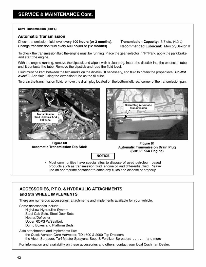
SERVICE & MAINTENANCE Cont.
42
Drive Transmission (con’t.)
Automatic Transmission
Check transmission fluid level every 100 hours (or 3 months).
Change transmission fluid every 600 hours or (12 months).
Transmission Capacity: 3.7 qts. (4.2 L)
Recommended Lubricant: Mercon/Dexron II
To drain the transmission fluid, remove the drain plug located on the bottom left, rear corner of the transmission pan.
Drain Plug AutomaticTransmission
Figure 61Automatic Transmission Drain Plug
(Suzuki K6A Engine)
To check the transmission fluid the engine must be running. Place the gear selector in “P” Park, apply the park brakeand start the engine.
With the engine running, remove the dipstick and wipe it with a clean rag. Insert the dipstick into the extension tubeuntil it contacts the tube. Remove the dipstick and read the fluid level.
Fluid must be kept between the twomarks on the dipstick. If necessary, add fluid to obtain the proper level. Do Notoverfill. Add fluid using the extension tube as the fill tube.
Figure 60Automatic Transmission Dip Stick
NOTICE
• Most communities have special sites to dispose of used petroleum basedproducts such as transmission fluid, engine oil and differential fluid. Pleaseuse an appropriate container to catch any fluids and dispose of properly.
TransmissionFluid Dipstick And
Fill Tube
ACCESSORIES, P.T.O. & HYDRAULIC ATTACHMENTS
and 5th WHEEL IMPLEMENTS
There are numerous accessories, attachments and implements available for your vehicle.
For information and availability on these accessories and others, contact your local Cushman Dealer.
Some accessories include:High/Low Hydraulics SystemSteel Cab Sets, Steel Door SetsHeater/DefrosterUpper ROPS W/SeatbeltDump Boxes and Platform Beds
Also attachments and implements like:the Quick Aerator, Core Harvester, TD 1500 & 2000 Top Dressersthe Vicon Spreader, Turf Master Sprayers, Seed & Fertilizer Spreaders and more. . . . . . .
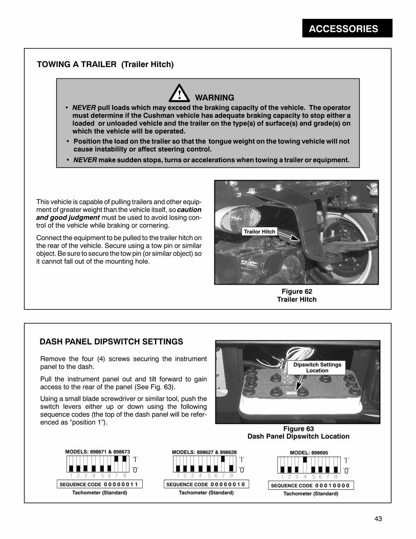
ACCESSORIES
43
Figure 62Trailer Hitch
This vehicle is capable of pulling trailers and other equip-ment of greater weight than the vehicle itself, so cautionand good judgmentmust be used to avoid losing con-trol of the vehicle while braking or cornering.
Connect the equipment to be pulled to the trailer hitch onthe rear of the vehicle. Secure using a tow pin or similarobject. Be sure to secure the towpin (or similar object) soit cannot fall out of the mounting hole.
Trailor Hitch
DASH PANEL DIPSWITCH SETTINGS
Remove the four (4) screws securing the instrumentpanel to the dash.
Pull the instrument panel out and tilt forward to gainaccess to the rear of the panel (See Fig. 63).
Using a small blade screwdriver or similar tool, push theswitch levers either up or down using the followingsequence codes (the top of the dash panel will be refer-enced as “position 1”).
Figure 63Dash Panel Dipswitch Location
Dipswitch SettingsLocation
SEQUENCE CODE 0 0 0 0 0 0 1 1
MODELS: 898671 & 898673
WARNING!NEVER pull loads which may exceed the braking capacity of the vehicle. The operatormust determine if the Cushman vehicle has adequate braking capacity to stop either aloaded or unloaded vehicle and the trailer on the type(s) of surface(s) and grade(s) onwhich the vehicle will be operated.
Position the load on the trailer so that the tongueweight on the towing vehicle will notcause instability or affect steering control.
NEVERmake sudden stops, turns or accelerations when towing a trailer or equipment.
TOWING A TRAILER (Trailer Hitch)
Tachometer (Standard)
SEQUENCE CODE 0 0 0 0 0 0 1 0
MODELS: 898627 & 898628
Tachometer (Standard)
SEQUENCE CODE 0 0 0 1 0 0 0 0
MODEL: 898695
Tachometer (Standard)
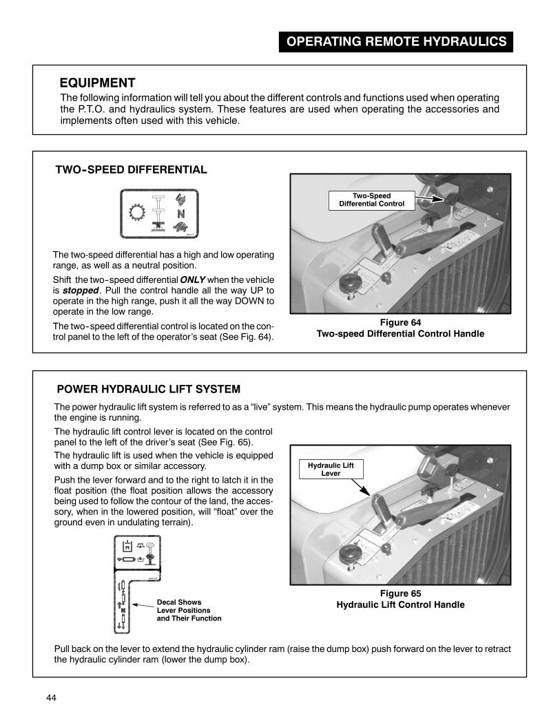
OPERATING REMOTE HYDRAULICS
44
EQUIPMENTThe following information will tell you about the different controls and functions used when operatingthe P.T.O. and hydraulics system. These features are used when operating the accessories andimplements often used with this vehicle.
TWO--SPEED DIFFERENTIAL
The two-speed differential has a high and low operatingrange, as well as a neutral position.
Shift the two--speed differentialONLYwhen the vehicleis stopped. Pull the control handle all the way UP tooperate in the high range, push it all the way DOWN tooperate in the low range.
The two--speed differential control is located on the con-trol panel to the left of the operator’s seat (See Fig. 64).
Figure 64
Two-speed Differential Control Handle
844177
POWER HYDRAULIC LIFT SYSTEM
The power hydraulic lift system is referred to as a “live” system. This means the hydraulic pump operates wheneverthe engine is running.
Figure 65
Hydraulic Lift Control Handle
Hydraulic LiftLever
Push the lever forward and to the right to latch it in thefloat position (the float position allows the accessorybeing used to follow the contour of the land, the acces-sory, when in the lowered position, will “float” over theground even in undulating terrain).
Pull back on the lever to extend the hydraulic cylinder ram (raise the dump box) push forward on the lever to retractthe hydraulic cylinder ram (lower the dump box).
The hydraulic lift is used when the vehicle is equippedwith a dump box or similar accessory.
844179
The hydraulic lift control lever is located on the controlpanel to the left of the driver’s seat (See Fig. 65).
Decal ShowsLever Positionsand Their Function
Two-SpeedDifferential Control

OPERATING REMOTE HYDRAULICS Cont.
45
The hydraulic system has a remote selector valve located at the front of the control panel, to operate accessoriessuch as the Core Harvester or Top Dresser.
REMOTE HYDRAULICS
NOTICE
• The “DOWN” position directs hydraulic oil to the stan-dard vehicle hydraulic lift system.
• The “UP” position directs hydraulic oil to the left side ofthe hydraulic panel for remote hydraulic system use.
• The vehicle is equipped with a hydraulic system to operate equipment. During operation,ALWAYS stay clear of moving parts to prevent injury.
WARNING!
844179
Decal ShowsRemote HydraulicFunctions
Figure 67
Remote Hydraulics Closed Loop Shown
When the remote hydraulics are not connected to equip-ment, themale and female quick connectorsmust be con-nected to form a closed loop (See Fig. 66).
It is extremely important that the hose nipple be insertedinto the quick connector to form a closed loop as shown.This will prevent dirt from entering the system and preventthe hydraulic system from over-heating, leading to systemfailure if the remote selector knob is accidentally pulled upwith the accessory removed.
Figure 66
Remote Hydraulics Control Handle
10
9
7
8
1 4
2
3
5
6
AccessoryCylinder
SelectorValve
LiftValve
Motor DrivenAccessory
HydraulicTank
HydraulicPump
PRESSURE
RETURN
SUCTION
PRESSURE OR RETURN
For Motor Driven Accessory AndTruckster Dump Box Operation:
Plug 1--4, 2--3, 8--9, 7--10.
For Motor Driven Accessory AndInoperable Truckster Cylinder:
Plug 1--2, 3--4, 8--9, 7--10.
For Truckster CylinderOperation:
Plug 1--4, 2--3, 7--8.
For Accessory CylinderOperation:
Plug 1--5, 2--6, 4--3, 7--8.
TrucksterCylinder
Filter
Make Sure Hose Is InsertedInto The Quick CouplerWhen An AccessoryIs Not Being Used.
Remote HydraulicsControl

OPERATING REMOTE HYDRAULICS Cont.
46
GOVERNOR CONTROL AND HAND THROTTLE
GOVERNORTHROTTLE
Amanually set, variable governor control is includedwiththe P.T.O. for regulation of P.T.O. or ground speed. Thecontrol lever is attached to the panel to the left of theinstrument panel. The hand throttle lever is attached tothe same panel.
Figure 68Governor and Hand Throttle Controls
GovernorControl
Hand ThrottleControl
The engine governor is preset to control engine (vehicle)ground speeds to design limits
The engine governor is preset to control engine ground (vehicle) speeds to design limits.
Normal mode:
• Hand throttle control lever in “DOWN” position.
• Variable governor control in “UP” position.
NOTICE
• (Diesel Only) In theNORMALMODE, the foot pedalthrottle retains full control of throttle lever position.An internal governor adjusts the injector pump tocompensate for variations in power requirements(maintains R.P.M. dictated by position of foot pedalthrottle).
WARNING!• To prevent speeds greater than design limits,NEVER alter the governor controls in anymanner to increase speedbeyond the recom-mended maximum R.P.M. Over--speedingmay result in engine failure and possibleinjury to operator and/or bystanders.
The P.T.O. transmits power from the transmission to asplined shaft at the rear of the vehicle for easy hook-up tooptional equipment.
Figure 69
P.T.O. Control Handle LocationPULL UP to engage. -- PUSH DOWN to disengage.
Thecontrol handle is locatedon the control panel to the leftof the operator’s seat.
POWER TAKE OFF (Mechanical P.T.O.)
There is also anoptional hydraulic poweredP.T.O. systemavailable. Refer to the section Power Take-Off (HydraulicP.T.O.) for proper operating instructions.
P.T.O.Control Handle
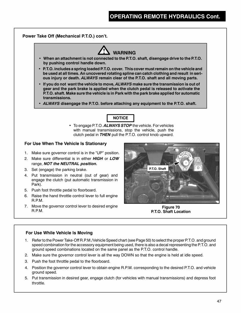
OPERATING REMOTE HYDRAULICS Cont.
47
• To engageP.T.O.ALWAYSSTOP the vehicle. For vehicleswith manual transmissions, stop the vehicle, push theclutch pedal in THEN pull the P.T.O. control knob upward.
For Use When The Vehicle Is Stationary
1. Make sure governor control is in the “UP” position.
NOTICE
2. Make sure differential is in either HIGH or LOW
range, NOT the NEUTRAL position.
• When an attachment is not connected to the P.T.O. shaft, disengage drive to the P.T.O.by pushing control handle down.
• P.T.O. includesaspring loadedP.T.O. cover. This covermust remain on the vehicle andbe used at all times. An uncovered rotating spline can catch clothing and result in seri-ous injury or death. ALWAYS remain clear of the P.T.O. shaft and all moving parts.
WARNING!
Power Take Off (Mechanical P.T.O.) con’t.
3. Set (engage) the parking brake.
4. Put transmission in neutral (out of gear) andengage the clutch (put automatic transmission inPark).
5. Push foot throttle pedal to floorboard.
6. Raise the hand throttle control lever to full engineR.P.M.
7. Move the governor control lever to desired engineR.P.M.
1. Refer to thePower Take-Off R.P.M./VehicleSpeedchart (seePage50) to select theproperP.T.O. andgroundspeedcombination for theaccessory equipment being used, there is also adecal representing the P.T.O. andground speed combinations located on the same panel as the P.T.O. control handle.
2. Make sure the governor control lever is all the way DOWN so that the engine is held at idle speed.
3. Push the foot throttle pedal to the floorboard.
4. Position the governor control lever to obtain engine R.P.M. corresponding to the desired P.T.O. and vehicleground speed.
5. Put transmission in desired gear, engage clutch (for vehicles with manual transmissions) and depress foot
throttle.
For Use While Vehicle Is Moving
P.T.O. Shaft
• If you do not want the vehicle tomove, ALWAYSmake sure the transmission is out ofgear and the park brake is applied when the clutch pedal is released to activate theP.T.O. shaft. Make sure the vehicle is in Parkwith the park brake applied for automatictransmissions.
• ALWAYS disengage the P.T.O. before attaching any equipment to the P.T.O. shaft.
Figure 70P.T.O. Shaft Location
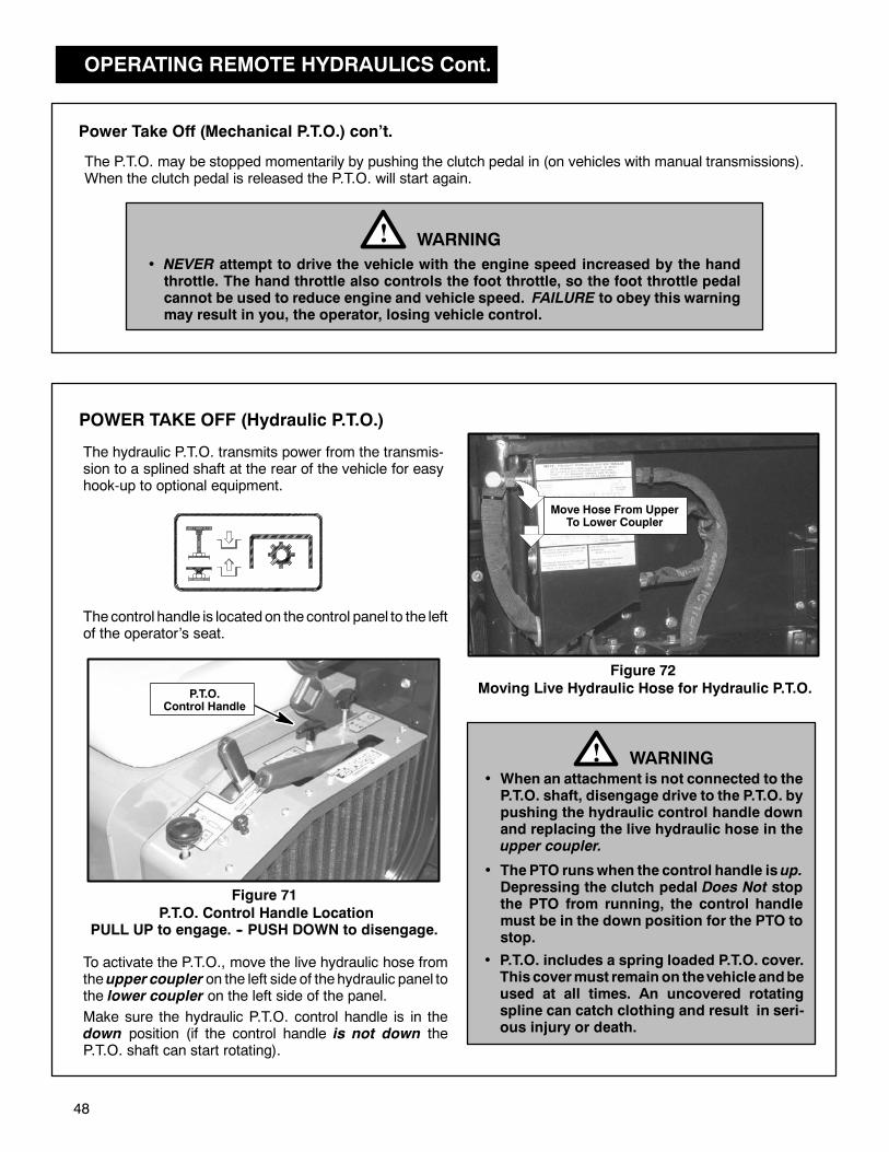
OPERATING REMOTE HYDRAULICS Cont.
48
P.T.O.Control Handle
Power Take Off (Mechanical P.T.O.) con’t.
WARNING!• NEVER attempt to drive the vehicle with the engine speed increased by the handthrottle. The hand throttle also controls the foot throttle, so the foot throttle pedalcannot be used to reduce engine and vehicle speed. FAILURE to obey this warningmay result in you, the operator, losing vehicle control.
The hydraulic P.T.O. transmits power from the transmis-sion to a splined shaft at the rear of the vehicle for easyhook-up to optional equipment.
Figure 71
P.T.O. Control Handle LocationPULL UP to engage. -- PUSH DOWN to disengage.
Thecontrol handle is locatedon the control panel to the leftof the operator’s seat.
POWER TAKE OFF (Hydraulic P.T.O.)
• When an attachment is not connected to theP.T.O. shaft, disengage drive to the P.T.O. bypushing the hydraulic control handle downand replacing the live hydraulic hose in theupper coupler.
WARNING!
To activate the P.T.O., move the live hydraulic hose fromtheupper coupler on the left side of thehydraulic panel tothe lower coupler on the left side of the panel.
Make sure the hydraulic P.T.O. control handle is in thedown position (if the control handle is not down theP.T.O. shaft can start rotating).
Move Hose From UpperTo Lower Coupler
• ThePTO runswhen the control handle isup.Depressing the clutch pedal Does Not stopthe PTO from running, the control handlemust be in the down position for the PTO tostop.
Figure 72
Moving Live Hydraulic Hose for Hydraulic P.T.O.
• P.T.O. includes a spring loaded P.T.O. cover.This covermust remain on thevehicle andbeused at all times. An uncovered rotatingspline can catch clothing and result in seri-ous injury or death.
The P.T.O. may be stopped momentarily by pushing the clutch pedal in (on vehicles with manual transmissions).When the clutch pedal is released the P.T.O. will start again.
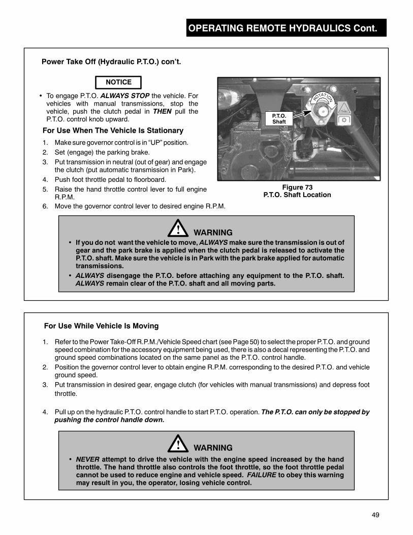
OPERATING REMOTE HYDRAULICS Cont.
49
• To engage P.T.O. ALWAYS STOP the vehicle. Forvehicles with manual transmissions, stop thevehicle, push the clutch pedal in THEN pull theP.T.O. control knob upward.
For Use While Vehicle Is Moving
For Use When The Vehicle Is Stationary
1. Make sure governor control is in “UP” position.
2. Set (engage) the parking brake.
3. Put transmission in neutral (out of gear) and engagethe clutch (put automatic transmission in Park).
4. Push foot throttle pedal to floorboard.
5. Raise the hand throttle control lever to full engineR.P.M.
NOTICE
Power Take Off (Hydraulic P.T.O.) con’t.
WARNING!• If you do not want the vehicle tomove, ALWAYSmake sure the transmission is out ofgear and the park brake is applied when the clutch pedal is released to activate theP.T.O. shaft. Make sure the vehicle is in Parkwith the park brake applied for automatictransmissions.
• ALWAYS disengage the P.T.O. before attaching any equipment to the P.T.O. shaft.ALWAYS remain clear of the P.T.O. shaft and all moving parts.
1. Refer to thePower Take-Off R.P.M./VehicleSpeedchart (seePage50) to select theproperP.T.O. andgroundspeedcombination for theaccessory equipment being used, there is also adecal representing the P.T.O. andground speed combinations located on the same panel as the P.T.O. control handle.
2. Position the governor control lever to obtain engine R.P.M. corresponding to the desired P.T.O. and vehicleground speed.
3. Put transmission in desired gear, engage clutch (for vehicles with manual transmissions) and depress foot
throttle.
4. Pull up on the hydraulic P.T.O. control handle to start P.T.O. operation. The P.T.O. can only be stopped bypushing the control handle down.
WARNING!• NEVER attempt to drive the vehicle with the engine speed increased by the handthrottle. The hand throttle also controls the foot throttle, so the foot throttle pedalcannot be used to reduce engine and vehicle speed. FAILURE to obey this warningmay result in you, the operator, losing vehicle control.
P.T.O.Shaft
Figure 73P.T.O. Shaft Location
6. Move the governor control lever to desired engine R.P.M.

OPERATING REMOTE HYDRAULICS Cont.
50
The following decal/charts show the vehicle’s ground speed in relation to the P.T.O.’s rpm. Select the properp.t.o. and ground speed combination for the accessory equipment being used.
GROUND SPEED CHARTS
The decals are applied to each of the appropriate turf models and are shown below with correct model identity.Please replace any decal which may become damaged and/or hard to read.
For use with Turf Model 898671
Suzuki 970 manual transmission
For use with Turf Models 898673 and
898695
Perkins Diesel with manual transmission
For use with Turf Model 898628
Suzuki K6A
with automatic transmission
For use with Turf Models 898627Suzuki K6Awith manual transmission

OPERATING REMOTE HYDRAULICS Cont.
51
Normally the hydraulic systemwill not need additional fluid. Sometimes a leakmay develop causing the systemto require repair and refilling. If you notice hydraulic fluid escaping when the system is being used or if a leakis suspected, turn off all hydraulic functions and stop the engine.
Periodically check the hydraulic fluid level (hydraulic level should be checked every 100 hours of operation).Loss of fluid can signal a small leak before it becomes worse.
To check the hydraulic fluid level:
1. Place vehicle on level surface. Fully lower any accessory attachment, including dump box. Stop thevehicle engine.
2. Remove the dipstick/breather plug from the top of the tank (See Figs. 74 and 75). Wipe the dipstick, thenplace in tankwith the threaded flange resting on the tank (donot screw in). Fluidshould showon theknurledportion of the dipstick (See Fig. 75). Add fluid as required.
3. Screw the dipstick/breather plug securely in place.
Do Not overfill the hydraulic system. Severe damage may result.Always reinstall the dipstick/breather plug.
If additional fluid is needed, add Ransomes Turf Protector Biodegradable hydraulic fluid.
NOTE:
Hydraulic System Capacity:Standard Hydraulics 4 gal. (15.0 L). . . . . .Hi-Lo Hydraulics 7.6 gal. (28.8 L). . . . . . . . .
Hydraulic Fluid (Biodegradable):2 1/2 gal. (9.5 L) Part No. 65363. . . . . . . . .5 gal. (19.0 L) Part No. 65352. . . . . . . . . . .55 gal. (208.0 L) Part No. 65354. . . . . . . . .
Check the hoses and fittings to determine where the fluid may be escaping from. If necessary, start the engineand using a piece of cardboard or similar material, check areas where the leak is suspected. Repair as needed.
WARNING!• Escaping hydraulic oil under pressure can have sufficient force to penetrate theskin, causing serious injury.
• After applying pressure to the system, use apiece of cardboard orwood,NOT yourhands, to check for leaks.
• If injured by escaping fluid, see doctor at once. Serious infection or reaction candevelop if proper medical treatment is not administered immediately.
Figure 75Hydraulic Tank Dipstick
Figure 74Hydraulic Reservoir Tank
HydraulicReservoir
Shown AsReference Only
HydraulicReservoir Dipstick
HYDRAULIC RESERVOIR
Knurled PortionOf Dipstick
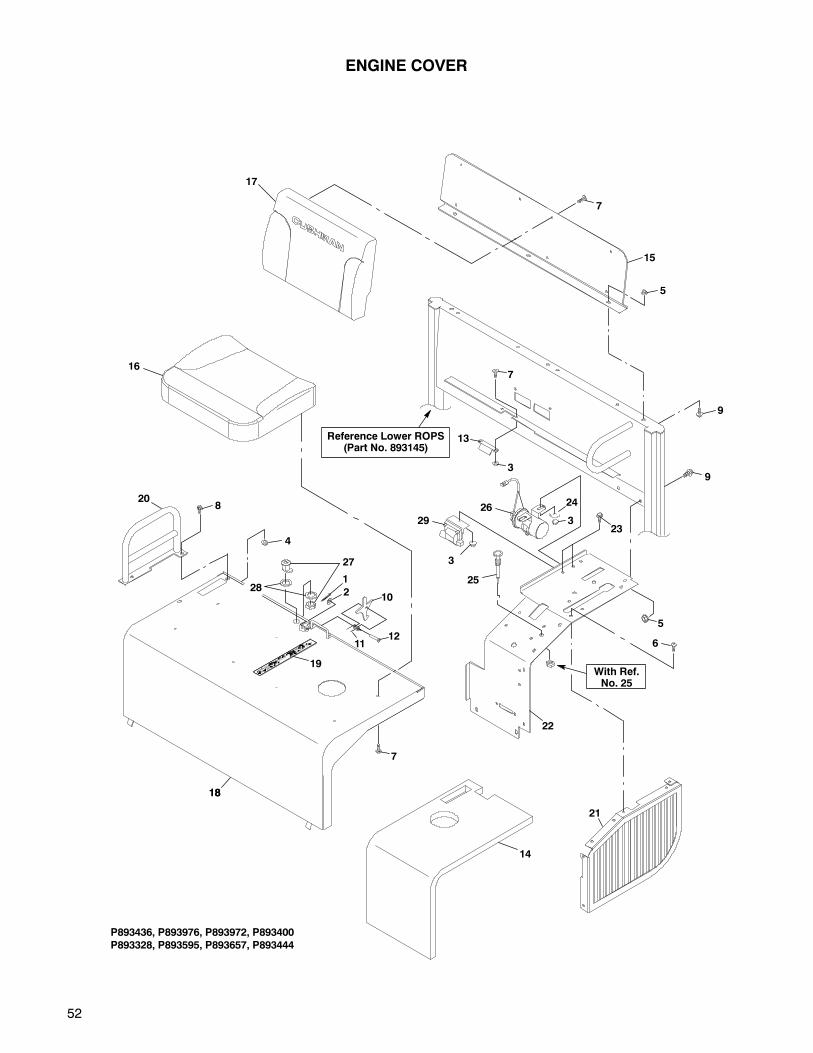
52
ENGINE COVER
16
5
7
15
17
14
P893436, P893976, P893972, P893400
P893328, P893595, P893657, P893444
3
9
7
13
9
29
Reference Lower ROPS(Part No. 893145)
21
6
5
22
233
25
2624
With Ref.No. 25
18
19
208
4
210
1211
1
18
7
27
28
3

53
ENGINE COVER
1 306328 Pin, cotter, .09 x .75 1. . . . . . . . . . .2 308090 Washer, 1/4 1. . . . . . . . . . . . . . . . . .3 450452 Nut, M6-1.00 (G10.9) 4. . . . . . . . . .4 450453 Nut, M8-1.25 (G10.9) 2. . . . . . . . . .5 450454 Nut, M10-1.50 (G10.9) 5. . . . . . . . .
6 800026 Screw, 1/4-20 x 3/4 7. . . . . . . . . . . .7 450541 Screw, M6-1.00 x 16 18. . . . . . . . . .8 452388 Screw, M8-1.25 x 20 (8.8) 2. . . . . .9 452398 Screw, M10-1.50 x 20 5. . . . . . . . .10 523085 Bracket 1. . . . . . . . . . . . . . . . . . . . . .
11 816401 Spring, torsion 1. . . . . . . . . . . . . . . .12 830784 Pin, clevis, .25 x 1.88 1. . . . . . . . . .13 841789 Catch, engine cover latch 1. . . . . .14 841804 Insulation, engine cover 3. . . . . . . .15 842030 Mount, backrest 2. . . . . . . . . . . . . . .16 893321 Seat, base assembly 2. . . . . . . . . .
17 894822 Seat, back assembly 2. . . . . . . . . .18 2700789 Cover, engine w/decal 1. . . . . . . .
19 845038 Decal, Operation 1. . . . . . . . . . . . .20 893541 Handhold (right side) 1. . . . . . . . . .21 894232 Cover, left 1. . . . . . . . . . . . . . . . . . . .22 2700796 Panel, console w/decals (turf) 1.
822819 Decal, Warning, Park Brake 1. . . .
844177 Decal, auxillary transmission 1. . .844179 Decal, hydraulic controls 1. . . . . .2700797 Panel, console (EC vehicles) 1. .845185 Decal, Warning, Park Brake (EC) 1844177 Decal, auxillary transmission 1. . .
844179 Decal, hydraulic controls 1. . . . . .23 800934 Screw, M6-1.00 x 16 (G10.9) 2. . .24 548175 Washer, 1/4 x 1 1/4 dia. 1. . . . . . . .25 841813 Cable, choke (Suzuki 970) 1. . . . .26 33410-85010 Coil, ignition (Suzuki 970) 1.27 840436 Lock, handle 1. . . . . . . . . . . . . . . . .
28 309488 Washer 2. . . . . . . . . . . . . . . . . . . . . .29 33410--50F20 Coil, ignition (Suzuki K6A). 1.
Ref.No.
PartNo. Description
No.Req’d
No.Req’dDescription
PartNo.
Ref.No.
Although Item No’s. 27 & 28 (handle lock and washers) are used on EC Models, they may be obtainedfor use on any of the models listed above.
*
**
• INDENTED PART NAMES INDICATE THESE PARTS ARE INCLUDED IN THE PRECEDING ASSEMBLY.
* Not Illustrated.
***
(22)
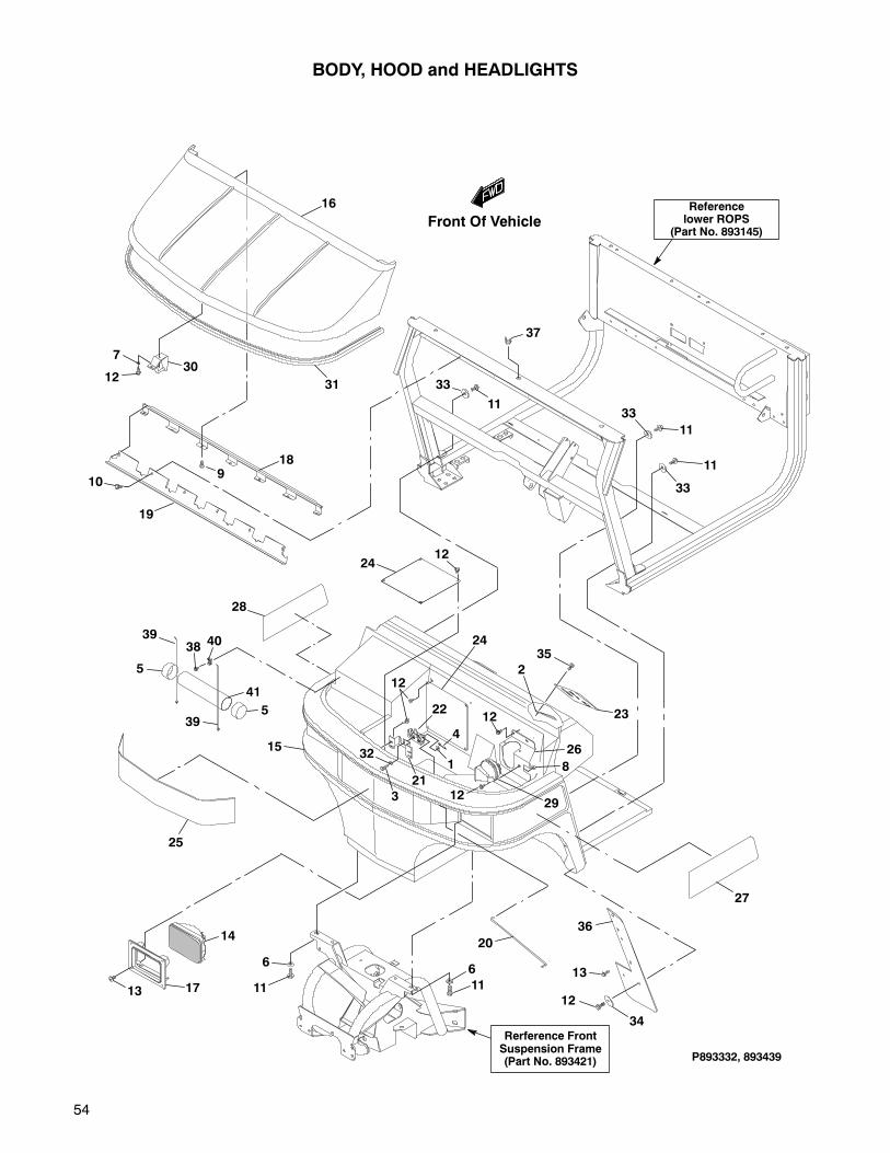
54
Rerference FrontSuspension Frame(Part No. 893421)
BODY, HOOD and HEADLIGHTS
24
12
22
1
4
2912
8
26
12
35
21
3
32
16
307
12
189
10
19
33
11
11
11
1224
28
25
15
13 17
14
11
6
20
11
6
27
P893332, 893439
37
31
33
33
36
13
12
34
23
2
Referencelower ROPS
(Part No. 893145)
38
39
3940
5
5
41
Front Of Vehicle
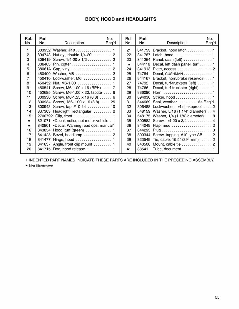
55
BODY, HOOD and HEADLIGHTS
1 303952 Washer, #10 1. . . . . . . . . . . . . . . . . .2 894743 Nut ay., double 1/4-20 2. . . . . . . . .3 306419 Screw, 1/4-20 x 1/2 2. . . . . . . . . . . .4 306463 Pin, cotter 1. . . . . . . . . . . . . . . . . . . .5 38061A Cap, vinyl 2. . . . . . . . . . . . . . . . . . . .
6 450400 Washer, M8 2. . . . . . . . . . . . . . . . . .7 450410 Lockwasher, M6 2. . . . . . . . . . . . . .8 450452 Nut, M6-1.00 1. . . . . . . . . . . . . . . . .9 450541 Screw, M6-1.00 x 16 (RPH) 7. . . .10 452695 Screw, M6-1.00 x 20, taptite 6. . . .
11 800930 Screw, M8-1.25 x 16 (8.8) 6. . . . . .12 800934 Screw, M6-1.00 x 16 (8.8) 25. . . .13 800943 Screw, tap, #10-14 10. . . . . . . . . . .14 837303 Headlight, rectangular 2. . . . . . . . .15 2700792 Clip, front 1. . . . . . . . . . . . . . . . . . .
821071 Decal, notice not motor vehicle 1.
840901 Decal, Warning read ops. manual116 843854 Hood, turf (green) 1. . . . . . . . . . . . .17 841428 Bezel, headlamp 2. . . . . . . . . . . . . .18 841477 Hinge, hood 1. . . . . . . . . . . . . . . . . .19 841637 Angle, front clip mount 1. . . . . . . . .
20 841715 Rod, hood release 1. . . . . . . . . . . . .
21 841753 Bracket, hood latch 1. . . . . . . . . . . .22 841787 Latch, hood 1. . . . . . . . . . . . . . . . . .23 841264 Panel, dash (left) 1. . . . . . . . . . . . . .
844116 Decal, left dash panel, turf 1. . . . . .24 841913 Plate, access 2. . . . . . . . . . . . . . . . .
25 74764 Decal, CUSHMAN 1. . . . . . . . . . . . . .26 844167 Bracket, horn/brake reservoir 1. . .27 74792 Decal, turf-truckster (left) 1. . . . . . .28 74766 Decal, turf-truckster (right) 1. . . . . .29 886090 Horn 1. . . . . . . . . . . . . . . . . . . . . . . .
30 894030 Striker, hood 1. . . . . . . . . . . . . . . . . .31 844669 Seal, weather As Req’d.. . . . . . . . . .32 306488 Lockwasher, 1/4 shakeproof 2. . . .33 548159 Washer, 5/16 (1 1/4” diameter) 4. .34 548175 Washer, 1/4 (1 1/4” diameter) 8. . .35 800582 Screw, 1/4-20 x 3/4 4. . . . . . . . . . . .
36 844049 Flap, mud 2. . . . . . . . . . . . . . . . . . . .37 844293 Plug 3. . . . . . . . . . . . . . . . . . . . . . . . .38 800344 Screw, tapping, #10 type AB 2. . . .39 823549 Tie, cable, 15.5” (394 mm) 2. . . . .40 840508 Mount, cable tie 2. . . . . . . . . . . . . . .
41 38541 Tube, document 1. . . . . . . . . . . . . .
Ref.No.
PartNo. Description
No.Req’d
No.Req’dDescription
PartNo.
Ref.No.
*
*
• INDENTED PART NAMES INDICATE THESE PARTS ARE INCLUDED IN THE PRECEDING ASSEMBLY.
* Not Illustrated.
*

56
FRAME
893326
10
6
6
6
3
17
3
3
4
29
ReferenceGround Wire
(Part No. 894602)
ReferenceMotor Mounts
32
5
1
4
1
Reference Battery& Hydraulic Tank
14
18
2
30
15
28
12
10
6
6
4
310
2510
3
6
6
21
22
5
20
2
6
31
3
32
9
11
3
5
3
6
32
26
29
9
19
23
Bolts ToRadiator Bracket
4
33
34
6
19
35
36
37
Front Of Vehicle
24
4
27
10 3
4
163
3
813
7

57
FRAME
1 309067 Lockwasher, 1/2 shakeproof 2. . . .2 450453 Nut, M8-1.25 (G10.9) 3. . . . . . . . . .3 450454 Nut, M10-1.50 (G10.9) 40. . . . . . . .4 450455 Nut, M12-1.75 (G10.9) 21. . . . . . . .5 452389 Screw, M8-1.25 x 25 (8.8) 3. . . . . .
6 452398 Screw, M10-1.50 x 20 (8.8) 27. . . .7 452402 Screw, M10-1.50 x 50 (8.8) 6. . . . .8 452403 Screw, M10-1.50 x 60 (8.8) 4. . . . .9 452405 Screw, M10-1.50 x 80 (8.8) 5. . . . .10 452410 Screw, M12-1.75 x 30 (8.8) 17. . . .
11 548911 Nut, 5/16-18 1. . . . . . . . . . . . . . . . . .12 800177 Screw, 5/16-18 x 3/4 1. . . . . . . . . . .13 800279 Nut, speed, 1/4-20 4. . . . . . . . . . . .14 800582 Screw, 1/4-20 x 3/4 4. . . . . . . . . . . .15 800930 Screw, M8-1.25 x 16 (8.8) 1. . . . . .16 841258 Bracket, drawbar 1. . . . . . . . . . . . . .
17 2700796 Panel, console, (turf) 1. . . . . . . . .822819 Decal, Warning Park Brake 1. . . .844177 Decal, auxillary transmission 1. . .844179 Decal, hydraulic controls 1. . . . . .2700797 Panel, console, (turf) 1. . . . . . . . .
845185 Decal, Warning Park Brake (EC) 1844177 Decal, auxillary transmission 1. . .844177 Decal, auxillary transmission 1. . .
18 841805 Panel, access 1. . . . . . . . . . . . . . . .
19 842870 Angle, support 2. . . . . . . . . . . . . . . .
20 844601 Bracket, battery clamp 1. . . . . . . . .
21 882971 Pin, disconnect 2. . . . . . . . . . . . . . .
22 809265 Pin, hair 25/32 x 2 11/16 1. . . . . .
23 893145 ROPS, lower 1. . . . . . . . . . . . . . . . .
24 893199.7 Platform, turf 1. . . . . . . . . . . . . . . .
also 893199G Platform, turf (galvanized) 1. . . .
25 893220 Drawbar, turf 1. . . . . . . . . . . . . . . . .
26 893235 Frame, main 1. . . . . . . . . . . . . . . . . .
also 893235G Frame, main (galv.) 1. . . . . . . . . .
27 893487 Fender (left) 1. . . . . . . . . . . . . . . . . .
28 893488 Fender (right) 1. . . . . . . . . . . . . . . . .
29 893525 Support, platform 2. . . . . . . . . . . . .
30 893527 Support, fuel tank 1. . . . . . . . . . . . .
31 894711 Guard, hydraulic tank 1. . . . . . . . . .
32 452406 Screw, M10-1.50 x 90 (8.8) 4. . . . .
33 452415 Screw, M12-1.75 x 80 (8.8) 8. . . . .
34 844729 Spacer, battery hold-down 1. . . . . .
35 844647 Angle, hold-down 1. . . . . . . . . . . . .
36 810437 Clamp, tube (Suzuki 970) 1. . . . . .
37 828382 Seal, foam As Req’d.. . . . . . . . . . . .
Ref.No.
PartNo. Description
No.Req’d
No.Req’dDescription
PartNo.
Ref.No.
Item No. 34 (Battery Hold-down Spacer, Part No. 844729) may not be used on all vehicles. If the batteryclamp cannot be adjusted to properly secure the battery, this spacer will be required.
• INDENTED PART NAMES INDICATE THESE PARTS ARE INCLUDED IN THE PRECEDING ASSEMBLY.
* Not Illustrated.
***
***
(17)
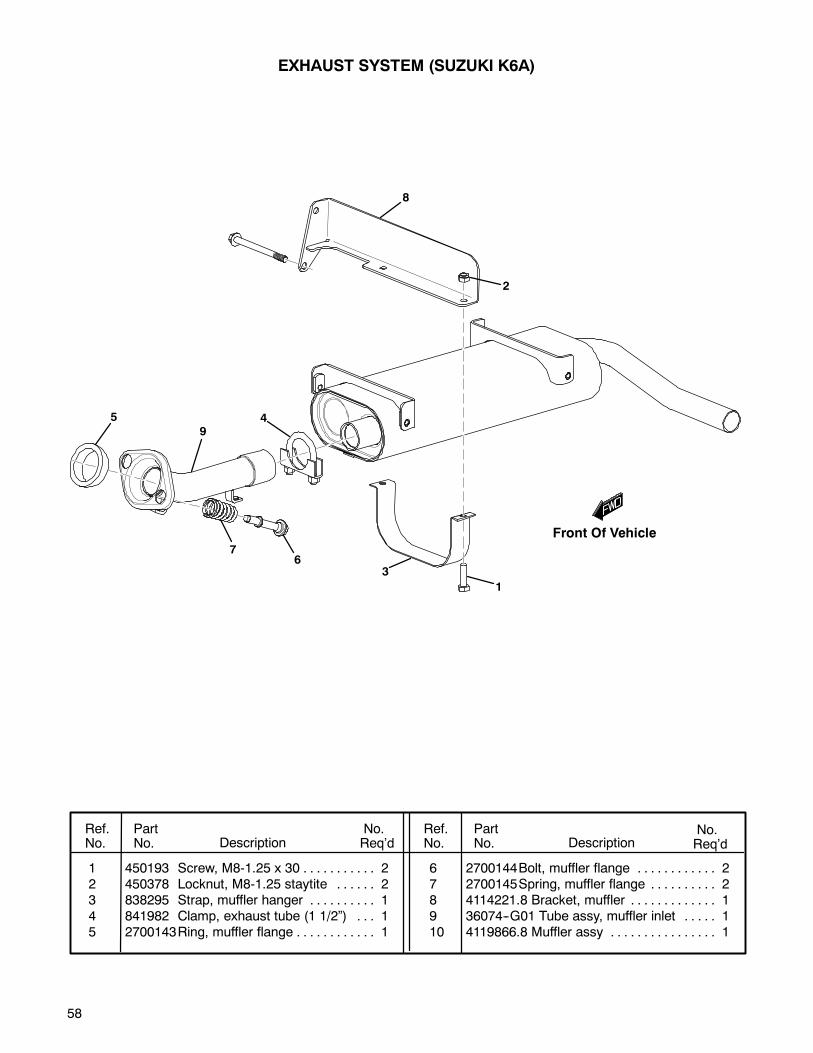
58
EXHAUST SYSTEM (SUZUKI K6A)
1 450193 Screw, M8-1.25 x 30 2. . . . . . . . . . .2 450378 Locknut, M8-1.25 staytite 2. . . . . .3 838295 Strap, muffler hanger 1. . . . . . . . . .4 841982 Clamp, exhaust tube (1 1/2”) 1. . .5 2700143Ring, muffler flange 1. . . . . . . . . . . .
6 2700144Bolt, muffler flange 2. . . . . . . . . . . .7 2700145Spring, muffler flange 2. . . . . . . . . .8 4114221.8 Bracket, muffler 1. . . . . . . . . . . . .9 36074--G01 Tube assy, muffler inlet 1. . . . .10 4119866.8 Muffler assy 1. . . . . . . . . . . . . . . .
Ref.No.
PartNo. Description
No.Req’d
No.Req’dDescription
PartNo.
Ref.No.
1
2
3
45
67
8
9
Front Of Vehicle

59
CALIFORNIA EXHAUST SYSTEM
(CATALYTIC CONVERTER) (SUZUKI K6A)
1 450193 Screw, M8-1.25 x 30 2. . . . . . . . . . .2 450378 Locknut, M8-1.25 staytite 2. . . . . .3 8388295.8 Strap, muffler hanger 1. . . . . . . .4 841982 Clamp, exhaust tube (1 1/2”) 1. . .5 270143 Ring, muffler flange 1. . . . . . . . . . . .
6 2700144Bolt, muffler flange 2. . . . . . . . . . . .7 2700145Spring, muffler flange0 1. . . . . . . .8 41124517.8 Bracket, muffler 1. . . . . . . . . . . .9 36072--G01 Converter AY, catalytic 1. . . . . .10 4116284.8 Muffler assembly 1. . . . . . . . . . .
11 841982 Decal, carb. Suzuki K6 1. . . . . . . . .12 412517.8 Shield, muffler 1. . . . . . . . . . . . . . .13 4121525.8 Shield, catalytic converter 1. . . .14 306450 Screw, 5/16 -- 18 X 3/4 4. . . . . . . . .15 306325 Lockwasher, 5/16 4. . . . . . . . . . . . .
16 103867 Washer, 5/16 4. . . . . . . . . . . . . . . . .17 306419 Screw, 1/4 2. . . . . . . . . . . . . . . . . . .18 306396 Lockwasher, 1/4 2. . . . . . . . . . . . . . .19 815680 Washer. special 2. . . . . . . . . . . . . . .
Ref.No.
PartNo. Description
No.Req’d
No.Req’dDescription
PartNo.
Ref.No.
Front Of Vehicle
2
1
34
5
67
9
10
12
13
1415
16
17
18
19
8
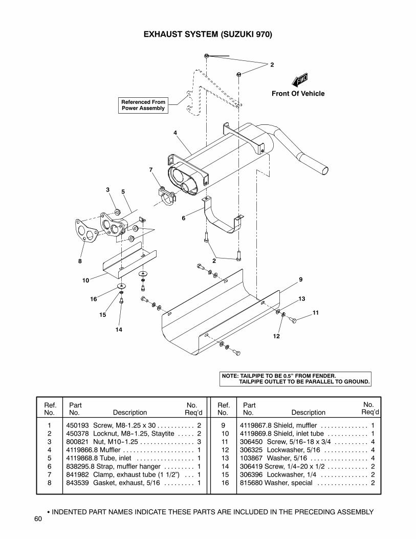
60
EXHAUST SYSTEM (SUZUKI 970)
1 450193 Screw, M8-1.25 x 30 2. . . . . . . . . . .2 450378 Locknut, M8--1.25, Staytite 2. . . . .3 800821 Nut, M10--1.25 3. . . . . . . . . . . . . . . .4 4119866.8 Muffler 1. . . . . . . . . . . . . . . . . . . . .5 4119868.8 Tube, inlet 1. . . . . . . . . . . . . . . . .
6 838295.8 Strap, muffler hanger 1. . . . . . . . .7 841982 Clamp, exhaust tube (1 1/2”) 1. . .8 843539 Gasket, exhaust, 5/16 1. . . . . . . . .
9 4119867.8 Shield, muffler 1. . . . . . . . . . . . . .10 4119869.8 Shield, inlet tube 1. . . . . . . . . . . .11 306450 Screw, 5/16--18 x 3/4 4. . . . . . . . . .12 306325 Lockwasher, 5/16 4. . . . . . . . . . . . .13 103867 Washer, 5/16 4. . . . . . . . . . . . . . . . .
14 306419 Screw, 1/4--20 x 1/2 2. . . . . . . . . . . .15 306396 Lockwasher, 1/4 2. . . . . . . . . . . . . .16 815680 Washer, special 2. . . . . . . . . . . . . . .
Ref.No.
PartNo. Description
No.Req’d
No.Req’dDescription
PartNo.
Ref.No.
INDENTED PART NAMES INDICATE THESE PARTS ARE INCLUDED IN THE PRECEDING ASSEMBLY
Referenced FromPower Assembly
2
4
7
53
8
10
16
15
1412
11
13
9
2
6
NOTE: TAILPIPE TO BE 0.5” FROM FENDER.TAILPIPE OUTLET TO BE PARALLEL TO GROUND.
Front Of Vehicle

61
EXHAUST SYSTEM (DIESEL)
1 103867 Washer, 5/16 2. . . . . . . . . . . . . . . . .2 450193 Screw, M8-1.25 staytite 2. . . . . . .3 450378 Locknut, M8--1.25, staytite 2. . . . .4 452389 Screw, M8--1.25 x 25 4. . . . . . . . . .5 4119866.8 Muffler ay 1. . . . . . . . . . . . . . . . . .
6 2703800.8 Tube, exhaust inlet 1. . . . . . . . . .7 841982 Clamp, tubing 2. . . . . . . . . . . . . . . .8 842234 Gasket, exhaust 1. . . . . . . . . . . . . .9 838295.8 Strap, muffler hanger 1. . . . . . . . .
Ref.No.
PartNo. Description
No.Req’d
No.Req’dDescription
PartNo.
Ref.No.
3
1
2
79
5
5
6
8
Referenced FromPower Assembly
NOTE: TAILPIPE TO BE 0.5” FROM FENDER.TAILPIPE OUTLET TO BE PARALLEL TO GROUND.
Front Of Vehicle

62
AIR CLEANER, BRACKET and FILTER
(SUZUKI K6A)
Ref.No.
PartNo. Description
INDENTED PART NAMES INDICATE THESE PARTS ARE INCLUDED IN THE PRECEDING ASSEMBLY
No.Req’dDescription
PartNo.
Ref.No.
No.Req’d
1 300646 Screw, 1/4-20 x 3/4 2. . . . . . . . . . . .2 306396 Lockwasher, 1/4 2. . . . . . . . . . . . . .3 308090 Washer, 1/4 2. . . . . . . . . . . . . . . . . .4 452389 Screw, M8-1.25 x 25 (8.8) 5. . . . . .5 450453 Nut, verbus rib M8 5. . . . . . . . . . . .
6 4115792.7 Bracket, air cleaner 1. . . . . . . . . .7 842915 Bracket, filter 1. . . . . . . . . . . . . . . . .8 4118027Filter assy, air 1. . . . . . . . . . . . . . . .9 840352 Element, air cleaner 1. . . . . . . . . .
10 825358 Clamp, worm drive 4. . . . . . . . . . . .11 4115401Hose, air cleaner 1. . . . . . . . . . . . . .12 4118423Elbow, street 1/4 1. . . . . . . . . . . . . .13 4118422Hose, barb--brass 1/4 1. . . . . . . . . .14 832033 Clamp, worm drive 2. . . . . . . . . . . .
15 825724 Hose, air cleaner 1. . . . . . . . . . . . . .16 841230 Connector, 3/8T x 1/8MP 1. . . . . . .17 832246 Hose, 3/8 heater As Req’d.. . . . . . .18 843666 Hose, air inake 1. . . . . . . . . . . . . . .
To RadiatorMounting Frame
16
321
10
15
10
Front Of Vehicle
4
5
9
8
18
10
1112
13
14
17

63
To RadiatorMounting Frame
5
1116
321
8
9
8
88
12
15
14
17
18
19
5
10
AIR CLEANER, BRACKET and FILTER
(SUZUKI 970 and DIESEL)
Ref.No.
PartNo. Description
INDENTED PART NAMES INDICATE THESE PARTS ARE INCLUDED IN THE PRECEDING ASSEMBLY
No.Req’dDescription
PartNo.
Ref.No.
No.Req’d
1 300646 Screw, 1/4-20 x 3/4 2. . . . . . . . . . . .2 306396 Lockwasher, 1/4 2. . . . . . . . . . . . . .3 308090 Washer, 1/4 2. . . . . . . . . . . . . . . . . .4 452388 Screw, M8-1.25 x 20 (8.8) 2. . . . . .5 452389 Screw, M8-1.25 x 25 (8.8) 2. . . . . .
6 450453 Nut, M8-1.25 (8.8) (Perkins) 2. . . .450453 Nut, M8-1.25 (8.8) (Suzuki 970) 4.
7 452390 Screw, M8-1.25 x 30 (8.8)(Perkins) 2. . . . . . . . . . . . . . . . . . . . .
8 825358 Clamp, worm-drive 4. . . . . . . . . . . .
9 825724 Hose, air cleaner 1. . . . . . . . . . . . . .10 817320 Clamp 1. . . . . . . . . . . . . . . . . . . . . . .11 842915 Bracket, air filter 1. . . . . . . . . . . . . .12 843666 Hose, air intake 1. . . . . . . . . . . . . . .13 843715 Bracket, air cleaner (Suzuki 970) 1
844311 Bracket, air cleaner (Perkins) 1. . .14 893182 Filter complete, air 1. . . . . . . . . . . .15 840352 Element, air cleaner 1. . . . . . . . . .16 888549 Connector, hose (air cleaner) 1. . .17 841230 Connector (Suzuki 970) 1. . . . . . . .
18 832246 Hose, 3/8” heater(Suzuki 970) As Req’d.. . . . . . . . . . .
19 843831 Connector, hose (Suzuki 970) 1. . .20 842997 Cap, 7/64 i.d. x 3/4 (Suzuki 970) 121 825884 Clamp, tube/wire (Suzuki 970) 1. .
22 844313 Hose, intake (Perkins) 1. . . . . . . . .23 841943 Inlet, air (Perkins) 1. . . . . . . . . . . . .24 842235 Gasket, air inlet (Perkins) 1. . . . . .25 452378 Screw, M6-1.00 x 20 (Perkins) 1. .26 800934 Screw, M6-1.00 x 16 (970) 1. . . . .
Items 11, 14 & 15Shown Assembled ToDepict Orientation OnThe Perkins Diesel.All components shown are used with both the
Suzuki 970 and the Perkins diesel unlessotherwise noted in the parts list shown below.
Right Side MotorMount (SUZUKI970) Shown ForReference Only
893444, 893594, 894197, 894198
207
6
21
4
8
13
6
5
25
23
24
8
22
6
13
WithPerkins Diesel
26Use
Loctite 592
(13)
(6)
Front Of Vehicle
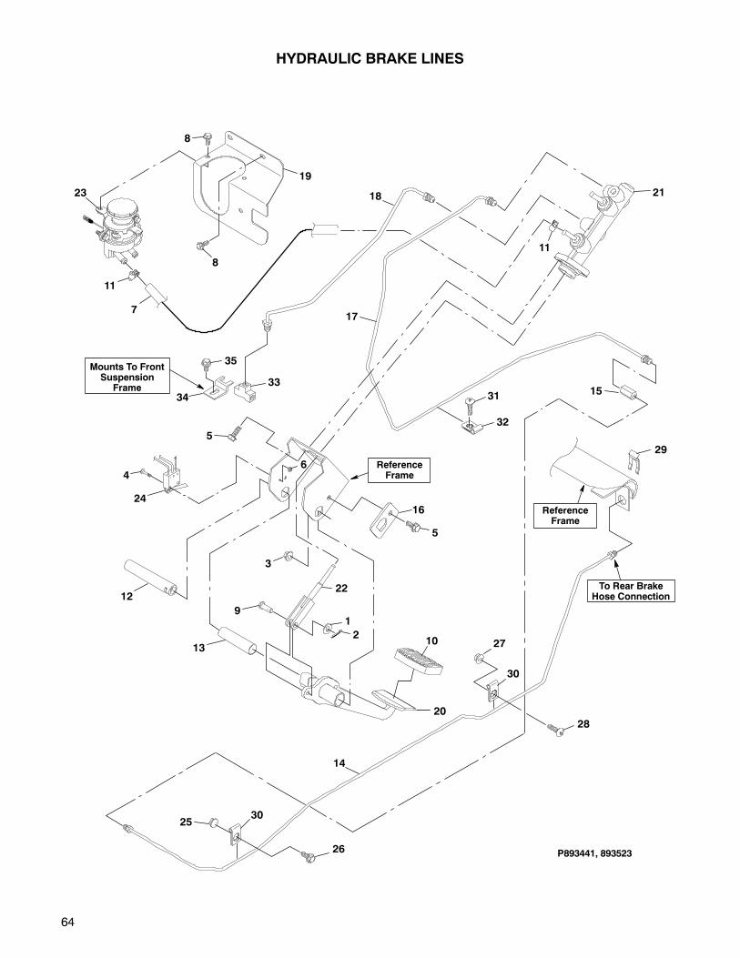
64
HYDRAULIC BRAKE LINES
P893441, 893523
8
8
19
23
11
717
11
21
14
15
ReferenceFrame
To Rear BrakeHose Connection
5
4
24
6
1
210
20
ReferenceFrame
12
13
3
9
22
16
5
2530
26
27
30
28
29
31
32
34
35Mounts To FrontSuspension
Frame
18
33
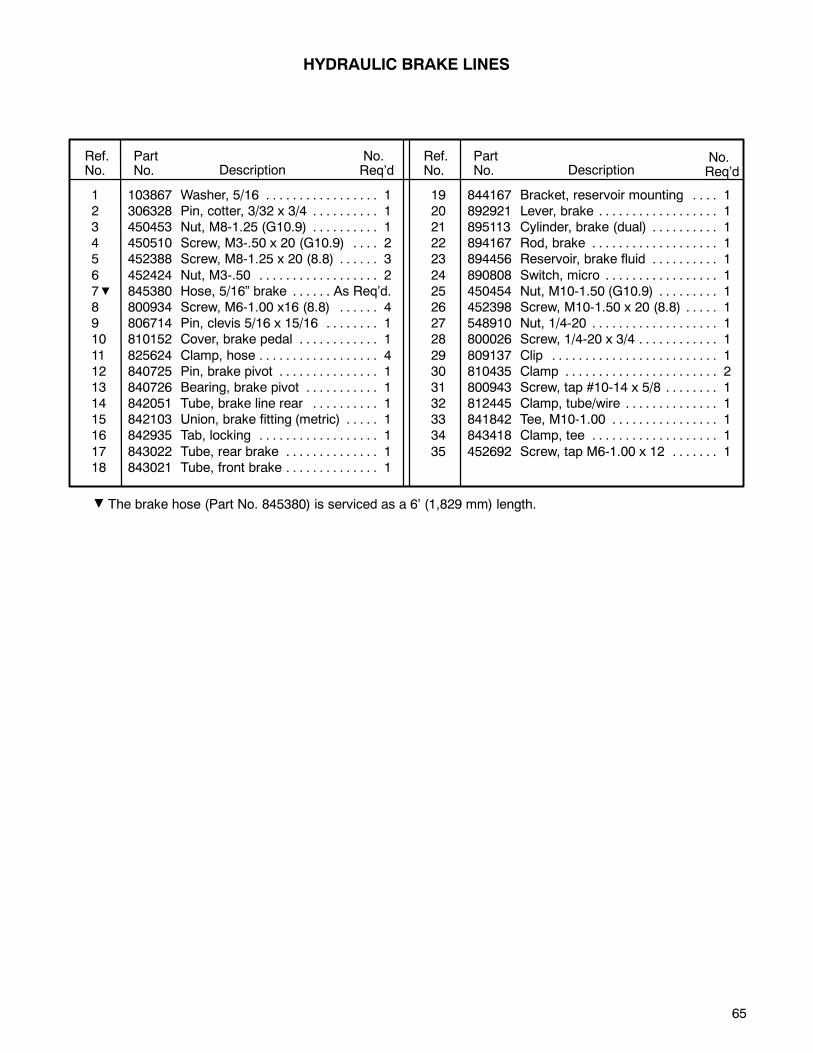
65
HYDRAULIC BRAKE LINES
1 103867 Washer, 5/16 1. . . . . . . . . . . . . . . . .2 306328 Pin, cotter, 3/32 x 3/4 1. . . . . . . . . .3 450453 Nut, M8-1.25 (G10.9) 1. . . . . . . . . .4 450510 Screw, M3-.50 x 20 (G10.9) 2. . . .5 452388 Screw, M8-1.25 x 20 (8.8) 3. . . . . .
6 452424 Nut, M3-.50 2. . . . . . . . . . . . . . . . . .7 845380 Hose, 5/16” brake As Req’d.. . . . . .8 800934 Screw, M6-1.00 x16 (8.8) 4. . . . . .9 806714 Pin, clevis 5/16 x 15/16 1. . . . . . . .10 810152 Cover, brake pedal 1. . . . . . . . . . . .
11 825624 Clamp, hose 4. . . . . . . . . . . . . . . . . .12 840725 Pin, brake pivot 1. . . . . . . . . . . . . . .13 840726 Bearing, brake pivot 1. . . . . . . . . . .14 842051 Tube, brake line rear 1. . . . . . . . . .15 842103 Union, brake fitting (metric) 1. . . . .16 842935 Tab, locking 1. . . . . . . . . . . . . . . . . .
17 843022 Tube, rear brake 1. . . . . . . . . . . . . .18 843021 Tube, front brake 1. . . . . . . . . . . . . .
19 844167 Bracket, reservoir mounting 1. . . .20 892921 Lever, brake 1. . . . . . . . . . . . . . . . . .21 895113 Cylinder, brake (dual) 1. . . . . . . . . .22 894167 Rod, brake 1. . . . . . . . . . . . . . . . . . .23 894456 Reservoir, brake fluid 1. . . . . . . . . .
24 890808 Switch, micro 1. . . . . . . . . . . . . . . . .25 450454 Nut, M10-1.50 (G10.9) 1. . . . . . . . .26 452398 Screw, M10-1.50 x 20 (8.8) 1. . . . .27 548910 Nut, 1/4-20 1. . . . . . . . . . . . . . . . . . .28 800026 Screw, 1/4-20 x 3/4 1. . . . . . . . . . . .
29 809137 Clip 1. . . . . . . . . . . . . . . . . . . . . . . . .30 810435 Clamp 2. . . . . . . . . . . . . . . . . . . . . . .31 800943 Screw, tap #10-14 x 5/8 1. . . . . . . .32 812445 Clamp, tube/wire 1. . . . . . . . . . . . . .33 841842 Tee, M10-1.00 1. . . . . . . . . . . . . . . .34 843418 Clamp, tee 1. . . . . . . . . . . . . . . . . . .
35 452692 Screw, tap M6-1.00 x 12 1. . . . . . .
Ref.No.
PartNo. Description
No.Req’d
No.Req’dDescription
PartNo.
Ref.No.
The brake hose (Part No. 845380) is serviced as a 6’ (1,829 mm) length.
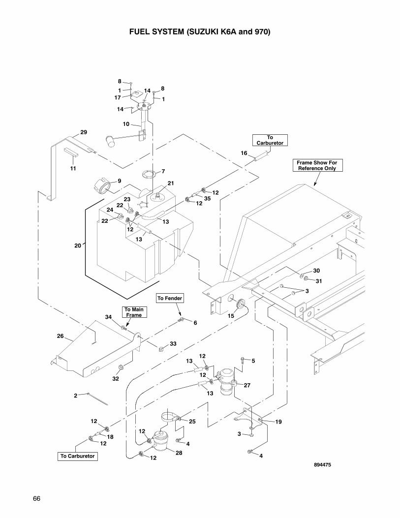
66
ToCarburetor
8
8
1
1
17
14
14
10
7
9
20
16
1235
12
21
23
22
24
12
13
22
13
1312
27
5
12
1228
4
25
3
4
19
2
12
13
12
1812
To Carburetor
FUEL SYSTEM (SUZUKI K6A and 970)
Frame Show ForReference Only
To MainFrame
To Fender
26
29
11
346
33
32
15
30
31
3
894475
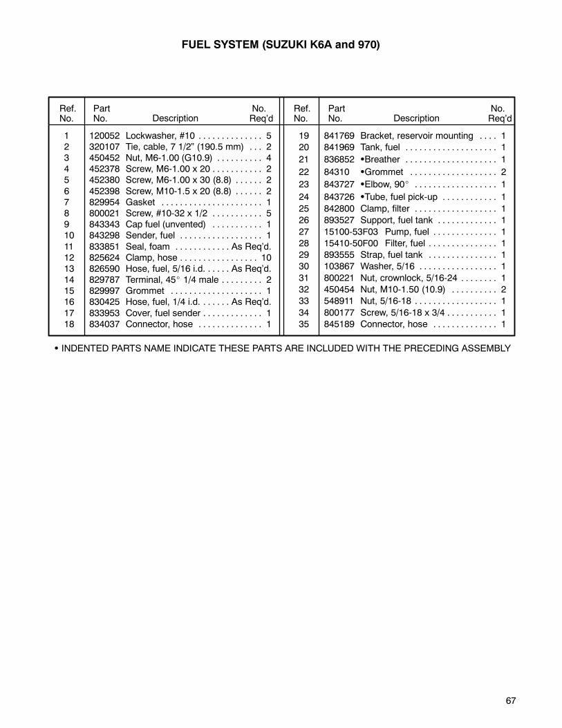
67
1 120052 Lockwasher, #10 5. . . . . . . . . . . . . .2 320107 Tie, cable, 7 1/2” (190.5 mm) 2. . .3 450452 Nut, M6-1.00 (G10.9) 4. . . . . . . . . .4 452378 Screw, M6-1.00 x 20 2. . . . . . . . . . .5 452380 Screw, M6-1.00 x 30 (8.8) 2. . . . . .
6 452398 Screw, M10-1.5 x 20 (8.8) 2. . . . . .7 829954 Gasket 1. . . . . . . . . . . . . . . . . . . . . .8 800021 Screw, #10-32 x 1/2 5. . . . . . . . . . .9 843343 Cap fuel (unvented) 1. . . . . . . . . . .10 843298 Sender, fuel 1. . . . . . . . . . . . . . . . . .
11 833851 Seal, foam As Req’d.. . . . . . . . . . . .12 825624 Clamp, hose 10. . . . . . . . . . . . . . . . .13 826590 Hose, fuel, 5/16 i.d. As Req’d.. . . . .14 829787 Terminal, 45 1/4 male 2. . . . . . . . .15 829997 Grommet 1. . . . . . . . . . . . . . . . . . . .16 830425 Hose, fuel, 1/4 i.d. As Req’d.. . . . . .
17 833953 Cover, fuel sender 1. . . . . . . . . . . . .18 834037 Connector, hose 1. . . . . . . . . . . . . .
19 841769 Bracket, reservoir mounting 1. . . .
20 841969 Tank, fuel 1. . . . . . . . . . . . . . . . . . . .
21 836852 Breather 1. . . . . . . . . . . . . . . . . . . .
22 84310 Grommet 2. . . . . . . . . . . . . . . . . . .
23 843727 Elbow, 90 1. . . . . . . . . . . . . . . . . .
24 843726 Tube, fuel pick-up 1. . . . . . . . . . . .
25 842800 Clamp, filter 1. . . . . . . . . . . . . . . . . .
26 893527 Support, fuel tank 1. . . . . . . . . . . . .
27 15100-53F03 Pump, fuel 1. . . . . . . . . . . . . .
28 15410-50F00 Filter, fuel 1. . . . . . . . . . . . . . .
29 893555 Strap, fuel tank 1. . . . . . . . . . . . . . .
30 103867 Washer, 5/16 1. . . . . . . . . . . . . . . . .
31 800221 Nut, crownlock, 5/16-24 1. . . . . . . .
32 450454 Nut, M10-1.50 (10.9) 2. . . . . . . . . .
33 548911 Nut, 5/16-18 1. . . . . . . . . . . . . . . . . .
34 800177 Screw, 5/16-18 x 3/4 1. . . . . . . . . . .
35 845189 Connector, hose 1. . . . . . . . . . . . . .
Ref.No.
PartNo. Description
No.Req’d
No.Req’dDescription
PartNo.
Ref.No.
INDENTED PARTS NAME INDICATE THESE PARTS ARE INCLUDED WITH THE PRECEDING ASSEMBLY
FUEL SYSTEM (SUZUKI K6A and 970)
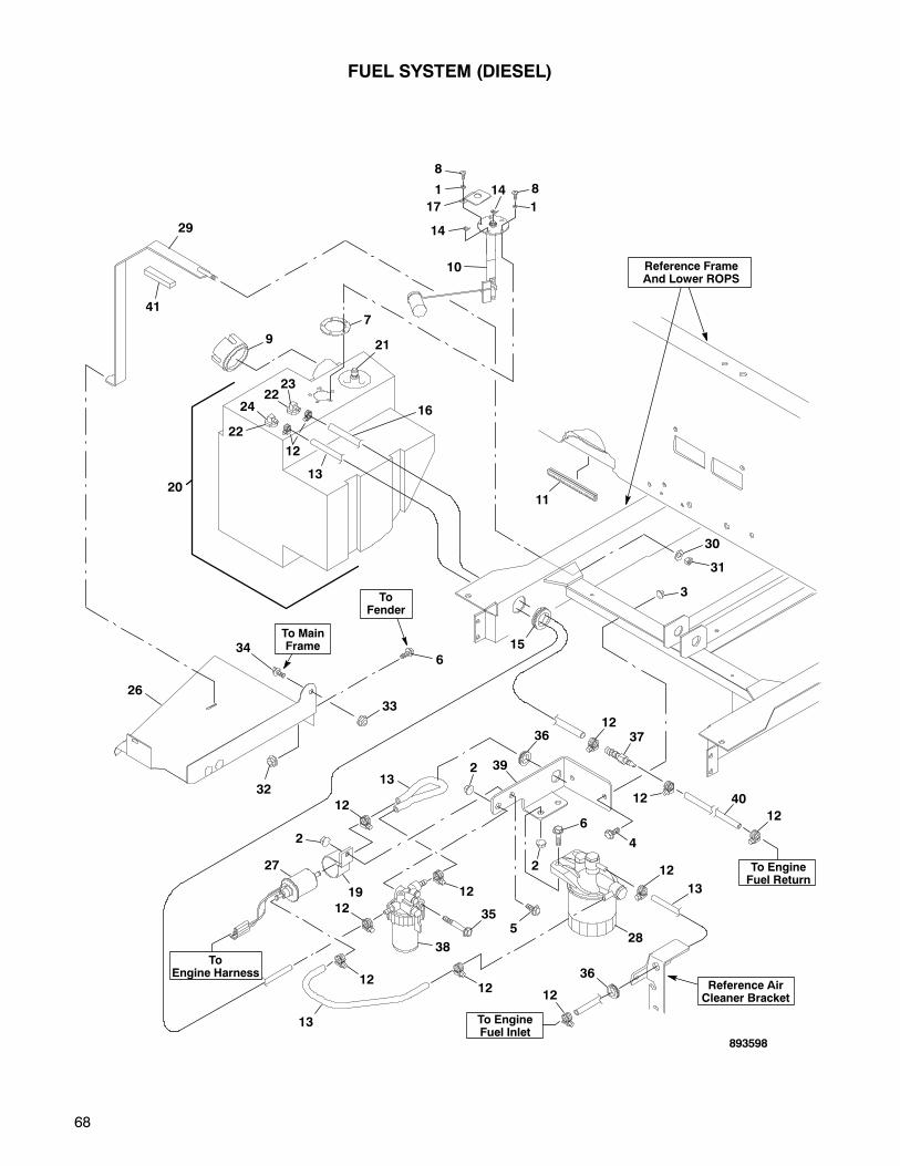
68
8
8
1
1
17
14
14
10
7
9
20
21
23
22
24
12
13
22
FUEL SYSTEM (DIESEL)
To MainFrame
ToFender
26
29
41
346
33
32
30
31
3
893598
ToEngine Harness
To EngineFuel Return
To EngineFuel Inlet
Reference FrameAnd Lower ROPS
Reference AirCleaner Bracket
16
11
1237
4
4012
12
12
36
13
36
1212
12
392
2
6
13
355
12
12
12
38
19
2
27
13
28
15
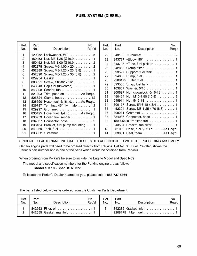
69
1 120052 Lockwasher, #10 5. . . . . . . . . . . . . .2 450453 Nut, M8-1.25 (G10.9) 4. . . . . . . . . .3 450452 Nut, M6-1.00 (G10.9) 2. . . . . . . . . .4 452378 Screw, M6-1.00 x 20 2. . . . . . . . . . .5 452389 Screw, M8-1.25 x 25 (8.8) 1. . . . . .
6 452390 Screw, M8-1.25 x 30 (8.8) 2. . . . . .7 829954 Gasket 1. . . . . . . . . . . . . . . . . . . . . .8 800021 Screw, #10-32 x 1/2 5. . . . . . . . . . .9 843343 Cap fuel (unvented) 1. . . . . . . . . . .10 843298 Sender, fuel 1. . . . . . . . . . . . . . . . . .
11 821893 Trim, push-on As Req’d.. . . . . . . . . .12 825624 Clamp, hose 12. . . . . . . . . . . . . . . . .13 826590 Hose, fuel, 5/16 i.d. As Req’d.. . . . .14 829787 Terminal, 45 1/4 male 2. . . . . . . . .15 829997 Grommet 1. . . . . . . . . . . . . . . . . . . .16 830425 Hose, fuel, 1/4 i.d. As Req’d.. . . . . .
17 833953 Cover, fuel sender 1. . . . . . . . . . . . .18 834037 Connector, hose 2. . . . . . . . . . . . . .19 838154 Bracket, fuel pump mounting 1. . .20 841969 Tank, fuel 1. . . . . . . . . . . . . . . . . . . .
21 836852 Breather 1. . . . . . . . . . . . . . . . . . . .
22 84310 Grommet 2. . . . . . . . . . . . . . . . . . .
23 843727 Elbow, 90 1. . . . . . . . . . . . . . . . . .
24 843726 Tube, fuel pick-up 1. . . . . . . . . . . .
25 842800 Clamp, filter 1. . . . . . . . . . . . . . . . . .
26 893527 Support, fuel tank 1. . . . . . . . . . . . .
27 894638 Pump, fuel 1. . . . . . . . . . . . . . . . . . .
28 2208175 Filter, fuel 1. . . . . . . . . . . . . . . . . . .
29 893555 Strap, fuel tank 1. . . . . . . . . . . . . . .
30 103867 Washer, 5/16 1. . . . . . . . . . . . . . . . .
31 800697 Nut, crownlock, 5/16-18 1. . . . . . . .
32 450454 Nut, M10-1.50 (10.9) 2. . . . . . . . . .
33 548911 Nut, 5/16-18 1. . . . . . . . . . . . . . . . . .
34 800177 Screw, 5/16-18 x 3/4 1. . . . . . . . . . .
35 452394 Screw, M8-1.25 x 70 (8.8) 1. . . . . .
36 809231 Grommet 2. . . . . . . . . . . . . . . . . . . .
37 834036 Connector, hose 1. . . . . . . . . . . . . .
38 130306180Pre-filter, fuel 1. . . . . . . . . . . . . . .
39 843534 Bracket, fuel filter 1. . . . . . . . . . . . .
40 831039 Hose, fuel 5/32 i.d. As Req’d.. . . . .
41 833851 Seal, foam As Req’d.. . . . . . . . . . . .
Ref.No.
PartNo. Description
No.Req’d
No.Req’dDescription
PartNo.
Ref.No.
INDENTED PARTS NAME INDICATE THESE PARTS ARE INCLUDED WITH THE PRECEDING ASSEMBLY
FUEL SYSTEM (DIESEL)
Certain engine parts will need to be ordered directly from Perkins. Ref No. 38, Fuel Pre-filter, shows thePerkin’s part number and is one of the parts which would be obtained from Perkin’s.
The model and specification numbers for the Perkins engine are as follows:
Model 103.10 - Spec. KD70377.
When ordering from Perkin’s be sure to include the Engine Model and Spec No’s.
The parts listed below can be ordered from the Cushman Parts Department.
To locate the Perkin’s Dealer nearest to you, please call: 1-888-737-5364
1 842553 Filter, oil 1. . . . . . . . . . . . . . . . . . . . .2 842555 Gasket, manifold 1. . . . . . . . . . . . . .
3 842235 Gasket, inlet 1. . . . . . . . . . . . . . . . . .4 2208175 Filter, fuel 1. . . . . . . . . . . . . . . . . . .
Ref.No.
PartNo. Description
No.Req’d
No.Req’dDescription
PartNo.
Ref.No.
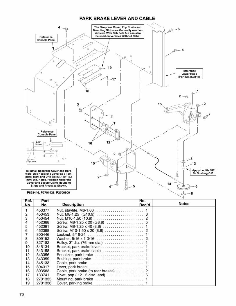
70
ReferenceLower Rops
(Part No. 893145)
ReferenceConsole Panel
P893446, P2701428, P2700600
4
64
2
2
1
15
11
3
7
12
10
2
4
2
149
8
8
13
5
PARK BRAKE LEVER AND CABLE
16
Apply Loctite 592To Bushing O.D.
The Neoprene Cover, Pop Rivets andMounting Strips are Generally used onVehicles With Cab Sets but can alsobe used on Vehicles Without Cabs.
19
18
17
To Install Neoprene Cover and Hard-ware, Use Neoprene Cover as a Tem-plate, Mark and Drill Six (6) .140” (3.5mm) Dia. Holes. Position NeopreneCover and Secure Using Mounting
Strips and Rivets as Shown.
2.85”(72.4 mm)
.44”(11.2 mm)
ReferenceConsole Panel
1 450377 Nut, staytite, M6-1.00 1. . . . . . . . . . . . . . . . . . . . . . . . .2 450453 Nut, M8-1.25 (G10.9) 6. . . . . . . . . . . . . . . . . . . . . . . .3 450454 Nut, M10-1.50 (10.9) 2. . . . . . . . . . . . . . . . . . . . . . . . . .4 452388 Screw, M8-1.25 x 20 (G8.8) 5. . . . . . . . . . . . . . . . . . .5 452391 Screw, M8-1.25 x 40 (8.8) 1. . . . . . . . . . . . . . . . . . . . .6 452398 Screw, M10-1.50 x 20 (8.8) 2. . . . . . . . . . . . . . . . . . . .7 800446 Locknut, 5/16-24 1. . . . . . . . . . . . . . . . . . . . . . . . . . . . .8 809152 Washer, 5/16 x 1 3/16 2. . . . . . . . . . . . . . . . . . . . . . . . .9 827182 Pulley, 3” dia. (76 mm dia.) 1. . . . . . . . . . . . . . . . . . . .10 845134 Bracket, park brake lever 1. . . . . . . . . . . . . . . . . . . . . .11 843158 Bracket, park brake cable 1. . . . . . . . . . . . . . . . . . . . .12 843356 Equalizer, park brake 1. . . . . . . . . . . . . . . . . . . . . . . . .13 843359 Bushing, park brake 1. . . . . . . . . . . . . . . . . . . . . . . . . .14 845133 Cable, park brake 1. . . . . . . . . . . . . . . . . . . . . . . . . . . .15 894317 Lever, park brake 1. . . . . . . . . . . . . . . . . . . . . . . . . . . . .16 893583 Cable, park brake (to rear brakes) 2. . . . . . . . . . . . . .17 133741 Rivet, pop (.12 .5 clsd. end) 6. . . . . . . . . . . . . . . . . . .18 2701335 Mounting, park brake 1. . . . . . . . . . . . . . . . . . . . . . . . .19 2701336 Cover, parking brake 1. . . . . . . . . . . . . . . . . . . . . . . . . .
Ref.No.
PartNo. Description Notes
No.Req’d

71
1 306328 Pin, cotter, 3/32 x 3/4 4. . . . . . . . . .2 844224 Pin, roll 3/16 x 1 3/4” 2. . . . . . . . . .3 450452 Nut, M6-1.00 (G10.9) 6. . . . . . . . . .4 452378 Screw, M6-1.00 x 20 6. . . . . . . . . . .5 452695 Screw, M6-1.00 x 20, taptite 1. . . .
6 515268 Bushing 2. . . . . . . . . . . . . . . . . . . . . .7 524633 Screw, shoulder 5/16-18 x 1 2. . . .8 524643 Bearing, split 2. . . . . . . . . . . . . . . . .9 548911 Nut, 5/16-18 2. . . . . . . . . . . . . . . . . .10 800943 Screw, tap, #10-14 x 5/8 10. . . . . .
11 806714 Pin, clevis, 5/16 x 3/4 3. . . . . . . . . .
12 844223 Spring, torsion 2. . . . . . . . . . . . . . . .13 830784 Pin, clevis, 1/4 x 1 7/8 1. . . . . . . . .14 841663 Panel, floor access 1. . . . . . . . . . . .15 843360 Channel, mount 1. . . . . . . . . . . . . . .16 843561 Link, throttle 1. . . . . . . . . . . . . . . . . .
17 843562 Mount, channel 1. . . . . . . . . . . . . . .18 843563 Plate, pivot 2. . . . . . . . . . . . . . . . . . .19 843997 Bracket, stop 1. . . . . . . . . . . . . . . . .20 894159 Pedal, throttle 1. . . . . . . . . . . . . . . .21 894540 Cable, throttle (Suzuki Models) 1. .
22 894618 Cable, throttle (Perkins) 1. . . . . . . .
Ref.No.
PartNo. Description
No.Req’d
No.Req’dDescription
PartNo.
Ref.No.
FOOT THROTTLE and LINKAGE
P893675, P893657, P893972, P893595, P894659
10
3
17
1
1
1
18
6
12
1318
2
19
11
11
3
7
15
9
54
4
20
1
811
16
14
12
ToEngine
2122
Pekins
Diesel
Suzuki 970Models
When attaching the throttlelink to the pedal, the pin (ItemNo. 11) will be inserted in thesecond hole from the top.
Front Of Vehicle
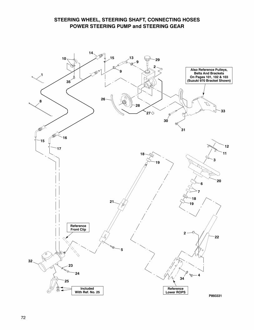
72
STEERING WHEEL, STEERING SHAFT, CONNECTING HOSES
POWER STEERING PUMP and STEERING GEAR
ReferenceLower ROPS
1
8
15
17
16
14
15
9
913
26
27
28
11
12
3
206
7
18
19
222
4
21
25
23
24
32
ReferenceFront Clip
P893331
33
31
30
IncludedWith Ref. No. 25
34
18
19
5
2
2910
35
Also Reference Pulleys,Belts And Brackets
On Pages 101, 102 & 103(Suzuki 970 Bracket Shown)

73
1 320107 Tie, cable, 7 1/2” (190 mm) 3. . . . .2 450453 Nut, M8-1.25 (G10.9) 4. . . . . . . . . .3 450457 Nut, M16-2.00 1. . . . . . . . . . . . . . . .4 800930 Screw, M8-1.25 x 16 (8.8) 2. . . . . .5 450739 Screw, socket head
M10-1.50 x 30 (8.8) 1. . . . . . . . . . .6 2700453 Cover 1. . . . . . . . . . . . . . . . . . . . . .7 819923 Collar, foam 2. . . . . . . . . . . . . . . . . .8 823549 Tie, cable, 15 1/2” (394 mm) 2. . . .9 830930 Clamp 2. . . . . . . . . . . . . . . . . . . . . . .
10 809092 Clamp, tube 2. . . . . . . . . . . . . . . . . .11 892486 Cover, steering wheel center 1. . . .12 839862 Decal, steering wheel 1. . . . . . . . .13 840222 Hose, 3/8 i.d. x 90 elbow 1. . . . . .14 843767 Hose, steering pressure 1. . . . . . . .15 111838 ‘O’-Ring 2. . . . . . . . . . . . . . . . . . . . .
16 843768 Hose, steering return 1. . . . . . . . . .17 111838 ‘O’-Ring 1. . . . . . . . . . . . . . . . . . . . .18 808060 Bearing, needle 2. . . . . . . . . . . . . . .19 828590 Housing, bearing 2. . . . . . . . . . . . . .20 892228 Wheel, steering (w/o horn) 1. . . . .
21 893344 Shaft, steering 1. . . . . . . . . . . . . . . .
22 893571 Tube, steering mount 1. . . . . . . . . .
23 303269 Lockwasher, 7/16 3. . . . . . . . . . . . .
24 311392 Screw, 7/16-14 x 2 3. . . . . . . . . . . .
25 841336 Arm, pitman 1. . . . . . . . . . . . . . . . . .
26 844301 V-belt, 48” (1219 mm) Perkins 1. .
(26) 836854 V-belt, 42” (1067 mm) Suzuki 970 1
27 892534 Pump, power steering 1. . . . . . . . .
28 839907 Pulley, steering pump 1. . . . . . . . .
29 2700573 Cap, steering pump reservoir 1.
30 452394 Screw, M8-1.25 x 70 (8.8) 2. . . . . .
31 452388 Screw, M8-1.25 x 20 (8.8) 4. . . . . .
32 841255 Gear, power steering 1. . . . . . . . . .
33 894362 Bracket, steering pump and
alt. mounting (Suzuki 970) 1. . . . . .
(33) 844268 Bracket, steering pump, rear
(Perkins Diesel) 1. . . . . . . . . . . . . . .
also 844272 Mount, engine, right
(Perkins Diesel) 1. . . . . . . . . . . . . . .
34 306799 Lockwasher,
5/16 external, shakeproof 2. . . . . .
35 800943 Screw, tap, #10-24 x 5/8 1. . . . . . .
Ref.No.
PartNo. Description
No.Req’d
No.Req’dDescription
PartNo.
Ref.No.
Service Parts for the pump are available at automotive centers. Refer to 1991-92 Buick Regalwith a 3.8L V6 engine (Saginaw Pump #26025515).
INDENTED PART NAMES INDICATE THESE PARTS ARE INCLUDED IN THE PRECEEDING ASSEMBLY.
STEERING WHEEL, STEERING SHAFT, CONNECTING HOSES
POWER STEERING PUMP and STEERING GEAR
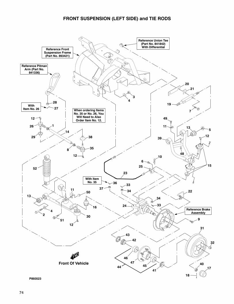
74
27
28
26
29
1
35
38
12
8
14
12
43
20
21
19
7
135
39
10
25
23
13
24
12
30
16
36
3733
34
33
34
24
22
15
12
31
32
P893523
Reference FrontSuspension Frame(Part No. 893421)
Reference PitmanArm (Part No.
841336)
Reference Union Tee(Part No. 841842)With Differential
Reference BrakeAssembly
18
40
17
46
47
44 45
41
43
42
9
6
5011
49
11
48
51
52
FRONT SUSPENSION (LEFT SIDE) and TIE RODS
When ordering ItemsNo. 35 or No. 26, YouWill Need to AlsoOrder Item No. 12.
With ItemNo. 35
WithItem No. 26
Front Of Vehicle
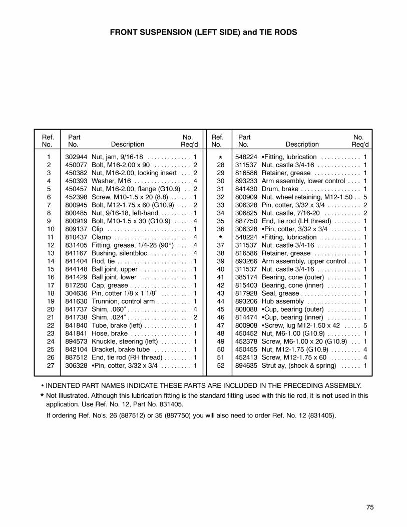
75
1 302944 Nut, jam, 9/16-18 1. . . . . . . . . . . . .2 450077 Bolt, M16-2.00 x 90 2. . . . . . . . . . .3 450382 Nut, M16-2.00, locking insert 2. . .4 450393 Washer, M16 4. . . . . . . . . . . . . . . . .5 450457 Nut, M16-2.00, flange (G10.9) 2. .
6 452398 Screw, M10-1.5 x 20 (8.8) 1. . . . . .7 800945 Bolt, M12-1.75 x 60 (G10.9) 2. . . .8 800485 Nut, 9/16-18, left-hand 1. . . . . . . . .9 800919 Bolt, M10-1.5 x 30 (G10.9) 4. . . . .10 809137 Clip 1. . . . . . . . . . . . . . . . . . . . . . . . .
11 810437 Clamp 4. . . . . . . . . . . . . . . . . . . . . . .12 831405 Fitting, grease, 1/4-28 (90 ) 4. . . .13 841167 Bushing, silentbloc 4. . . . . . . . . . . .14 841404 Rod, tie 1. . . . . . . . . . . . . . . . . . . . . .15 844148 Ball joint, upper 1. . . . . . . . . . . . . . .16 841429 Ball joint, lower 1. . . . . . . . . . . . . . .
17 817250 Cap, grease 1. . . . . . . . . . . . . . . . . .18 304636 Pin, cotter 1/8 x 1 1/8” 1. . . . . . . . .19 841630 Trunnion, control arm 1. . . . . . . . . .20 841737 Shim, .060” 4. . . . . . . . . . . . . . . . . . .21 841738 Shim, .024” 2. . . . . . . . . . . . . . . . . . .
22 841840 Tube, brake (left) 1. . . . . . . . . . . . . .23 841841 Hose, brake 1. . . . . . . . . . . . . . . . . .24 894573 Knuckle, steering (left) 1. . . . . . . . .25 842104 Bracket, brake tube 1. . . . . . . . . . .26 887512 End, tie rod (RH thread) 1. . . . . . . .
27 306328 Pin, cotter, 3/32 x 3/4 1. . . . . . . . .
548224 Fitting, lubrication 1. . . . . . . . . . . .28 311537 Nut, castle 3/4-16 1. . . . . . . . . . . . .29 816586 Retainer, grease 1. . . . . . . . . . . . . .30 893233 Arm assembly, lower control 1. . . .31 841430 Drum, brake 1. . . . . . . . . . . . . . . . . .
32 800909 Nut, wheel retaining, M12-1.50 5. .33 306328 Pin, cotter, 3/32 x 3/4 2. . . . . . . . . .34 306825 Nut, castle, 7/16-20 2. . . . . . . . . . .35 887750 End, tie rod (LH thread) 1. . . . . . . .36 306328 Pin, cotter, 3/32 x 3/4 1. . . . . . . . .
548224 Fitting, lubrication 1. . . . . . . . . . . .37 311537 Nut, castle 3/4-16 1. . . . . . . . . . . . .38 816586 Retainer, grease 1. . . . . . . . . . . . . .39 893266 Arm assembly, upper control 1. . . .40 311537 Nut, castle 3/4-16 1. . . . . . . . . . . . .41 385174 Bearing, cone (outer) 1. . . . . . . . . .
42 815403 Bearing, cone (inner) 1. . . . . . . . . .43 817928 Seal, grease 1. . . . . . . . . . . . . . . . . .44 893206 Hub assembly 1. . . . . . . . . . . . . . . .45 808088 Cup, bearing (outer) 1. . . . . . . . . .46 814474 Cup, bearing (inner) 1. . . . . . . . . .
47 800908 Screw, lug M12-1.50 x 42 5. . . . .48 450452 Nut, M6-1.00 (G10.9) 1. . . . . . . . . .49 452378 Screw, M6-1.00 x 20 (G10.9) 1. . .50 450455 Nut, M12-1.75 (G10.9) 4. . . . . . . . .51 452413 Screw, M12-1.75 x 60 4. . . . . . . . .
52 894635 Strut ay, (shock & spring) 1. . . . . .
Ref.No.
PartNo. Description
No.Req’d
No.Req’dDescription
PartNo.
Ref.No.
*
*
• INDENTED PART NAMES INDICATE THESE PARTS ARE INCLUDED IN THE PRECEDING ASSEMBLY.
* Not Illustrated. Although this lubrication fitting is the standard fitting used with this tie rod, it is not used in thisapplication. Use Ref. No. 12, Part No. 831405.
FRONT SUSPENSION (LEFT SIDE) and TIE RODS
If ordering Ref. No’s. 26 (887512) or 35 (887750) you will also need to order Ref. No. 12 (831405).

76
FRONT SUSPENSION (RIGHT SIDE) TIE RODS and SKID PLATE
41
40
13
28
21
177
10
25 26
27
18
2
3
30
31
9
39
19
15
12
47
3415
1
20
37
417
38
48
833
14
32
22
35
36
45
46
56
6
42
43
43
42
44
15
49
15
893523, 893329
5152
53
5456
55
24
57
23
29
11
16
Reference Brakesand Brake Shoes
5059
58
60
48
61
60
62
63
When ordering ItemsNo. 34 or No. 44,
You Will Need to AlsoOrder Item No. 15.
With ItemNo. 44
With ItemNo. 34
Front Of Vehicle

77
1 302944 Nut, jam, 9/16-18 1. . . . . . . . . . . . .2 303269 Lockwasher, 7/16 3. . . . . . . . . . . . .3 311392 Screw, 7/16-14 x 2 3. . . . . . . . . . . .4 450077 Bolt, M16-2.00 x 90 2. . . . . . . . . . .5 450382 Nut, locking insert M16-2.00 2. . . .
6 450393 Washer, M16 4. . . . . . . . . . . . . . . . .7 450457 Nut, M16-2.00, flange (G10.9) 2. .8 452398 Screw, M10-1.5 x 20 (8.8) 1. . . . . .9 452408 Screw, M10-1.75 x 20 (G10.9) 6. .10 800945 Bolt, M12-1.75 x 60 (G10.9) 2. . . .
11 452692 Screw, M6-1.00 x 12 1. . . . . . . . . . .12 800485 Nut, 9/16-18, left-hand 1. . . . . . . . .13 800919 Bolt, M10-1.5 x 30 4. . . . . . . . . . . . .14 809137 Clip 1. . . . . . . . . . . . . . . . . . . . . . . . .15 831405 Fitting, grease 1/4-28 (90 ) 4. . . . .16 843418 Clamp, tee 1. . . . . . . . . . . . . . . . . . .
17 841167 Bushing, silentbloc 4. . . . . . . . . . . .18 841255 Gear, power steering 1. . . . . . . . . .19 841336 Arm, pitman 1. . . . . . . . . . . . . . . . . .20 841404 Rod, tie 1. . . . . . . . . . . . . . . . . . . . . .21 844148 Ball joint, upper 1. . . . . . . . . . . . . . .
22 841429 Ball joint, lower 1. . . . . . . . . . . . . . .23 304636 Pin, cotter 1/8 x 1 1/8 1. . . . . . . . . .24 817250 Cap, grease 1. . . . . . . . . . . . . . . . . .25 841630 Trunnion, control arm 1. . . . . . . . . .26 841737 Shim, .060” 4. . . . . . . . . . . . . . . . . . .
27 841738 Shim, .024” 2. . . . . . . . . . . . . . . . . . .28 841839 Tube, brake (right) 1. . . . . . . . . . . .29 841841 Hose, brake 1. . . . . . . . . . . . . . . . . .30 841842 Tee, union, M10-1.00 flare 1. . . . . .31 842033 Plate, skid 1. . . . . . . . . . . . . . . . . . . .
32 894574 Knuckle, steering (right) 1. . . . . . . .33 842104 Bracket, brake tube 1. . . . . . . . . . .
34 887512 End, tie rod (RH thread) 1. . . . . . . .
35 306328 Pin, cotter, 3/32 x 3/4 1. . . . . . . . .
548224 Fitting, lubrication 1. . . . . . . . . . . .
36 306825 Nut, castle, 7/16-20 1. . . . . . . . . . .
37 816586 Retainer, grease 1. . . . . . . . . . . . . .
38 893234 Arm assembly, lower control 1. . . .
39 893421 Frame assembly, front 1. . . . . . . . .
40 841430 Drum, brake 1. . . . . . . . . . . . . . . . . .
41 800909 Nut, wheel retaining, M12-1.50 5. .
42 306328 Pin, cotter, 3/32 x 3/4 2. . . . . . . . . .
43 306825 Nut, castle, 7/16-20 2. . . . . . . . . . .
44 887750 End, tie rod (LH thread) 1. . . . . . . .
45 306328 Pin, cotter, 3/32 x 3/4 1. . . . . . . . .
548224 Fitting, lubrication 1. . . . . . . . . . . .
46 306825 Nut, castle, 7/16-20 1. . . . . . . . . . .
47 816586 Retainer, grease 1. . . . . . . . . . . . . .
48 810437 Clamp 4. . . . . . . . . . . . . . . . . . . . . . .
49 893266 Arm assembly, upper control 1. . . .
50 385174 Bearing, cone (outer) 1. . . . . . . . . .
51 815403 Bearing, cone (inner) 1. . . . . . . . . .
52 817928 Seal, grease 1. . . . . . . . . . . . . . . . . .
53 893206 Hub assembly 1. . . . . . . . . . . . . . . .
54 808088 Cup, bearing (outer) 1. . . . . . . . . .
55 814474 Cup, bearing (inner) 1. . . . . . . . . .
56 800908 Screw, lug M12-1.50 x 42 5. . . . .
57 311537 Nut, castle 3/4-16 1. . . . . . . . . . . . .
58 450452 Nut, M6-1.00, flange (G10.9) 1. . .
59 452378 Screw, M6-1.00 x 20 1. . . . . . . . . .
60 450455 Nut, M12-1.75 (G10.9) 12. . . . . . . .
61 452413 Screw, M12-1.75 x 60 4. . . . . . . . .
62 452415 Screw, M12-1.75 x 80 (8.8) 8. . . . .
63 894635 Strut ay. (shock & spring) 2. . . . . .
Ref.No.
PartNo. Description
No.Req’d
No.Req’dDescription
PartNo.
Ref.No.
*
*
FRONT SUSPENSION (RIGHT SIDE) TIE RODS and SKID PLATE
• INDENTED PART NAMES INDICATE THESE PARTS ARE INCLUDED IN THE PRECEDING ASSEMBLY.
* Not Illustrated. Although this lubrication fitting is the standard fitting used with this tie rod, it is not used in thisapplication. Use Ref. No. 15, Part No. 831405.
If ordering Ref. No’s. 34 (887512) or 44 (887750) you will also need to order Ref. No. 15 (831405).
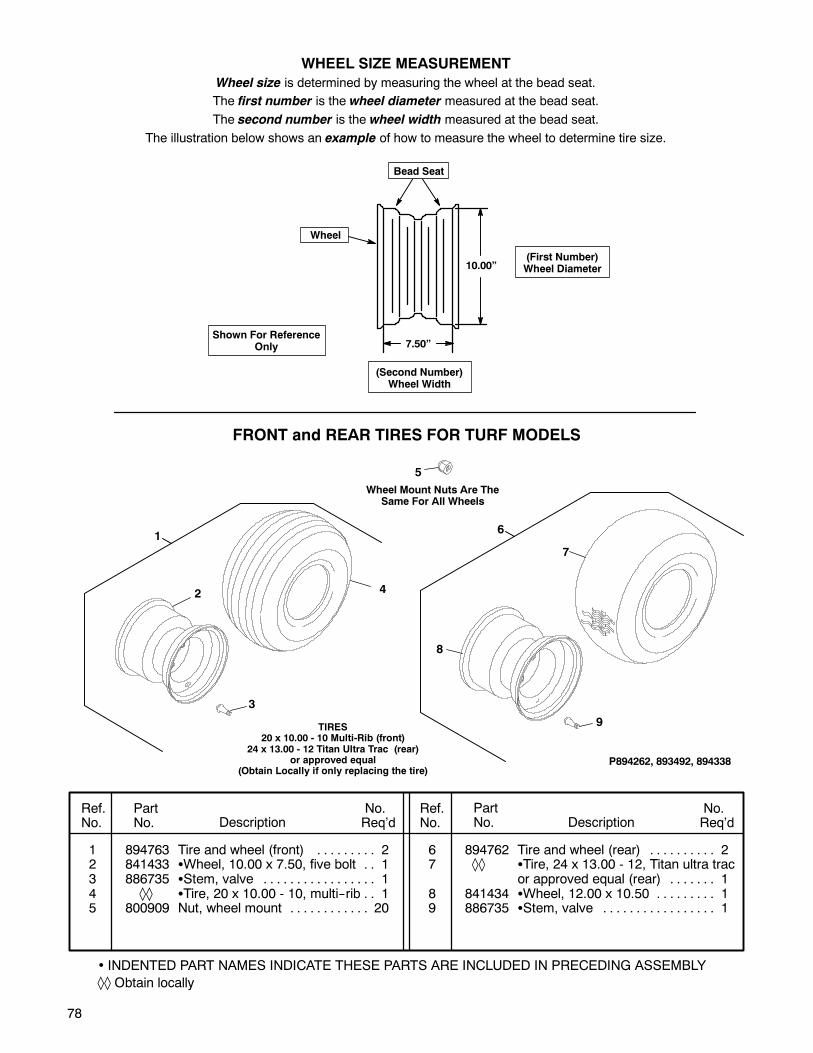
78
• INDENTED PART NAMES INDICATE THESE PARTS ARE INCLUDED IN PRECEDING ASSEMBLY
Obtain locally
Ref.No.
PartNo. Description
No.Req’d
No.Req’dDescription
PartNo.
Ref.No.
1 894763 Tire and wheel (front) 2. . . . . . . . .2 841433 Wheel, 10.00 x 7.50, five bolt 1. .3 886735 Stem, valve 1. . . . . . . . . . . . . . . . .4 Tire, 20 x 10.00 - 10, multi--rib 1. .5 800909 Nut, wheel mount 20. . . . . . . . . . . .
6 894762 Tire and wheel (rear) 2. . . . . . . . . .7 Tire, 24 x 13.00 - 12, Titan ultra trac
or approved equal (rear) 1. . . . . . .8 841434 Wheel, 12.00 x 10.50 1. . . . . . . . .9 886735 Stem, valve 1. . . . . . . . . . . . . . . . .
WHEEL SIZE MEASUREMENT
Wheel size is determined by measuring the wheel at the bead seat.
The first number is the wheel diameter measured at the bead seat.
The second number is the wheel width measured at the bead seat.
The illustration below shows an example of how to measure the wheel to determine tire size.
7.50”
10.00”
Bead Seat
(First Number)Wheel Diameter
(Second Number)Wheel Width
Wheel
Shown For ReferenceOnly
TIRES20 x 10.00 - 10 Multi-Rib (front)
24 x 13.00 - 12 Titan Ultra Trac (rear)or approved equal
(Obtain Locally if only replacing the tire)
FRONT and REAR TIRES FOR TURF MODELS
P894262, 893492, 894338
1
2 4
3
5
8
Wheel Mount Nuts Are TheSame For All Wheels
7
9
6
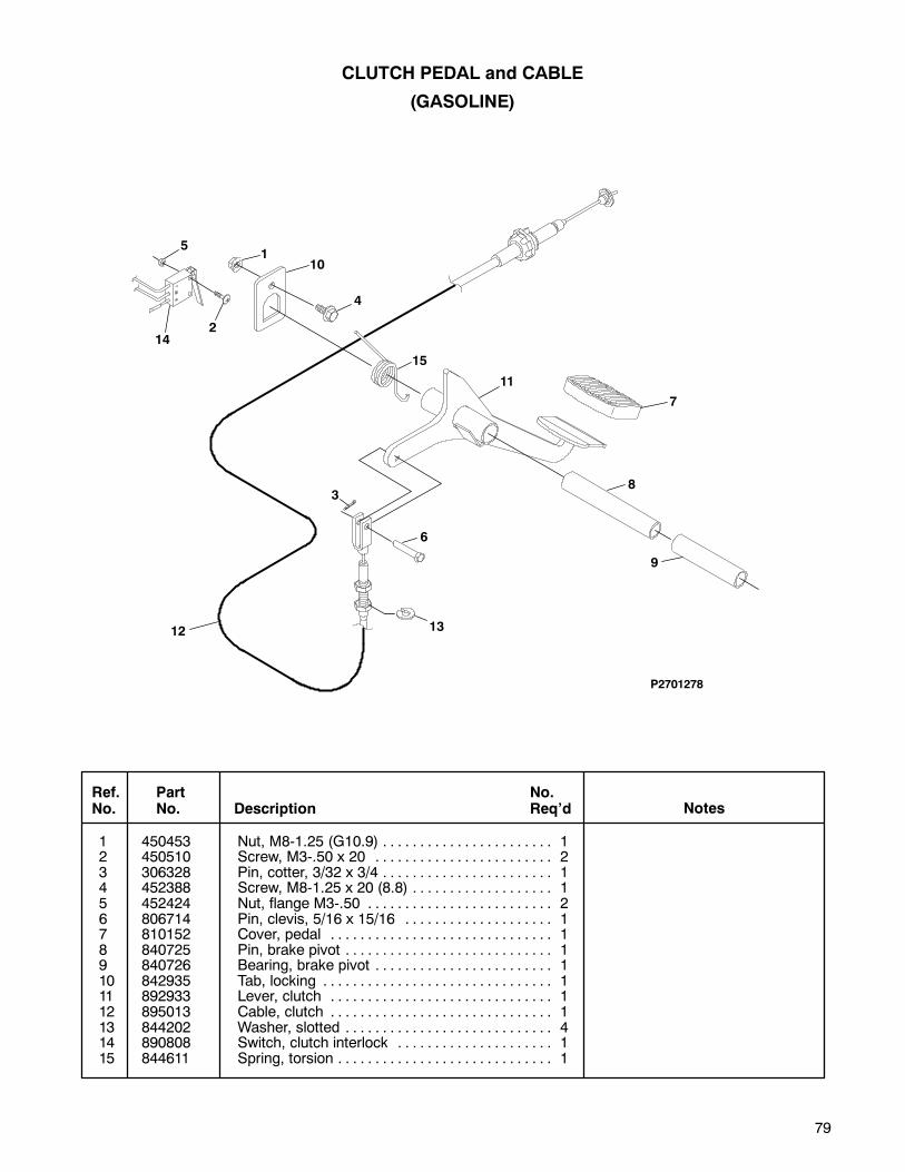
79
CLUTCH PEDAL and CABLE
(GASOLINE)
1 450453 Nut, M8-1.25 (G10.9) 1. . . . . . . . . . . . . . . . . . . . . . .2 450510 Screw, M3-.50 x 20 2. . . . . . . . . . . . . . . . . . . . . . . .3 306328 Pin, cotter, 3/32 x 3/4 1. . . . . . . . . . . . . . . . . . . . . . .4 452388 Screw, M8-1.25 x 20 (8.8) 1. . . . . . . . . . . . . . . . . . .5 452424 Nut, flange M3-.50 2. . . . . . . . . . . . . . . . . . . . . . . . .6 806714 Pin, clevis, 5/16 x 15/16 1. . . . . . . . . . . . . . . . . . . .7 810152 Cover, pedal 1. . . . . . . . . . . . . . . . . . . . . . . . . . . . . .8 840725 Pin, brake pivot 1. . . . . . . . . . . . . . . . . . . . . . . . . . . .9 840726 Bearing, brake pivot 1. . . . . . . . . . . . . . . . . . . . . . . .10 842935 Tab, locking 1. . . . . . . . . . . . . . . . . . . . . . . . . . . . . . .11 892933 Lever, clutch 1. . . . . . . . . . . . . . . . . . . . . . . . . . . . . .12 895013 Cable, clutch 1. . . . . . . . . . . . . . . . . . . . . . . . . . . . . .13 844202 Washer, slotted 4. . . . . . . . . . . . . . . . . . . . . . . . . . . .14 890808 Switch, clutch interlock 1. . . . . . . . . . . . . . . . . . . . .15 844611 Spring, torsion 1. . . . . . . . . . . . . . . . . . . . . . . . . . . . .
Ref.No.
PartNo. Description Notes
No.Req’d
P2701278
1
2
3
4
5
6
7
8
9
10
11
12 13
14
15
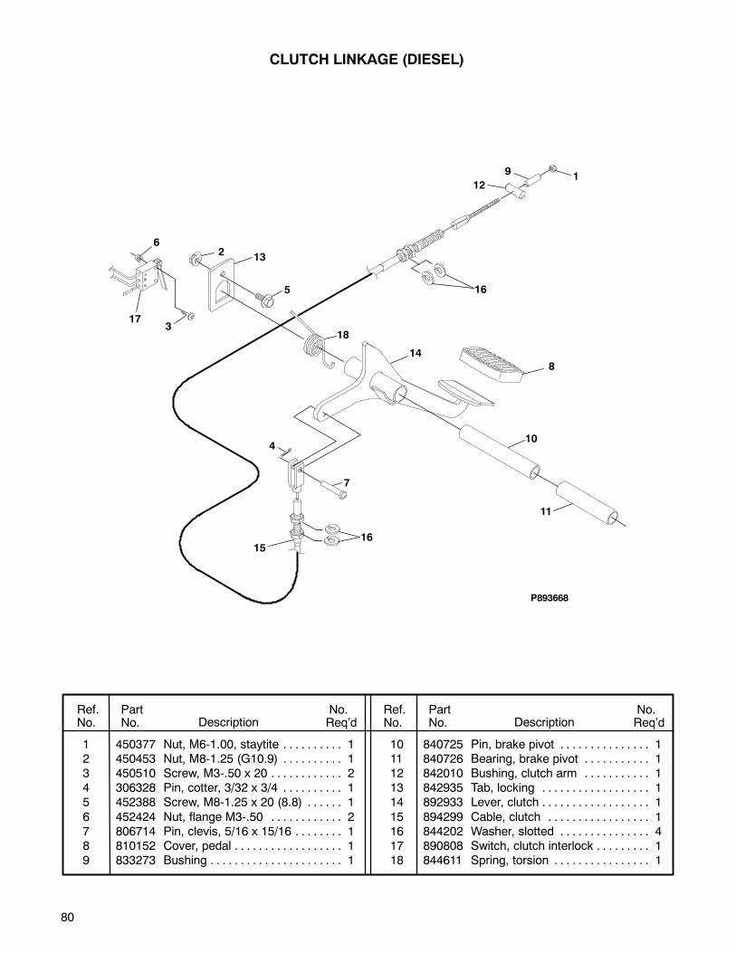
80
CLUTCH LINKAGE (DIESEL)
Ref.No.
PartNo. Description
No.Req’d
No.Req’dDescription
PartNo.
Ref.No.
1 450377 Nut, M6-1.00, staytite 1. . . . . . . . . .2 450453 Nut, M8-1.25 (G10.9) 1. . . . . . . . . .3 450510 Screw, M3-.50 x 20 2. . . . . . . . . . . .4 306328 Pin, cotter, 3/32 x 3/4 1. . . . . . . . . .5 452388 Screw, M8-1.25 x 20 (8.8) 1. . . . . .
6 452424 Nut, flange M3-.50 2. . . . . . . . . . . .7 806714 Pin, clevis, 5/16 x 15/16 1. . . . . . . .8 810152 Cover, pedal 1. . . . . . . . . . . . . . . . . .9 833273 Bushing 1. . . . . . . . . . . . . . . . . . . . . .
10 840725 Pin, brake pivot 1. . . . . . . . . . . . . . .11 840726 Bearing, brake pivot 1. . . . . . . . . . .12 842010 Bushing, clutch arm 1. . . . . . . . . . .13 842935 Tab, locking 1. . . . . . . . . . . . . . . . . .14 892933 Lever, clutch 1. . . . . . . . . . . . . . . . . .
15 894299 Cable, clutch 1. . . . . . . . . . . . . . . . .16 844202 Washer, slotted 4. . . . . . . . . . . . . . .17 890808 Switch, clutch interlock 1. . . . . . . . .18 844611 Spring, torsion 1. . . . . . . . . . . . . . . .
P893668
1
2
3
4
5
6
7
8
9
12
13
14
15
16
16
17
18
10
11
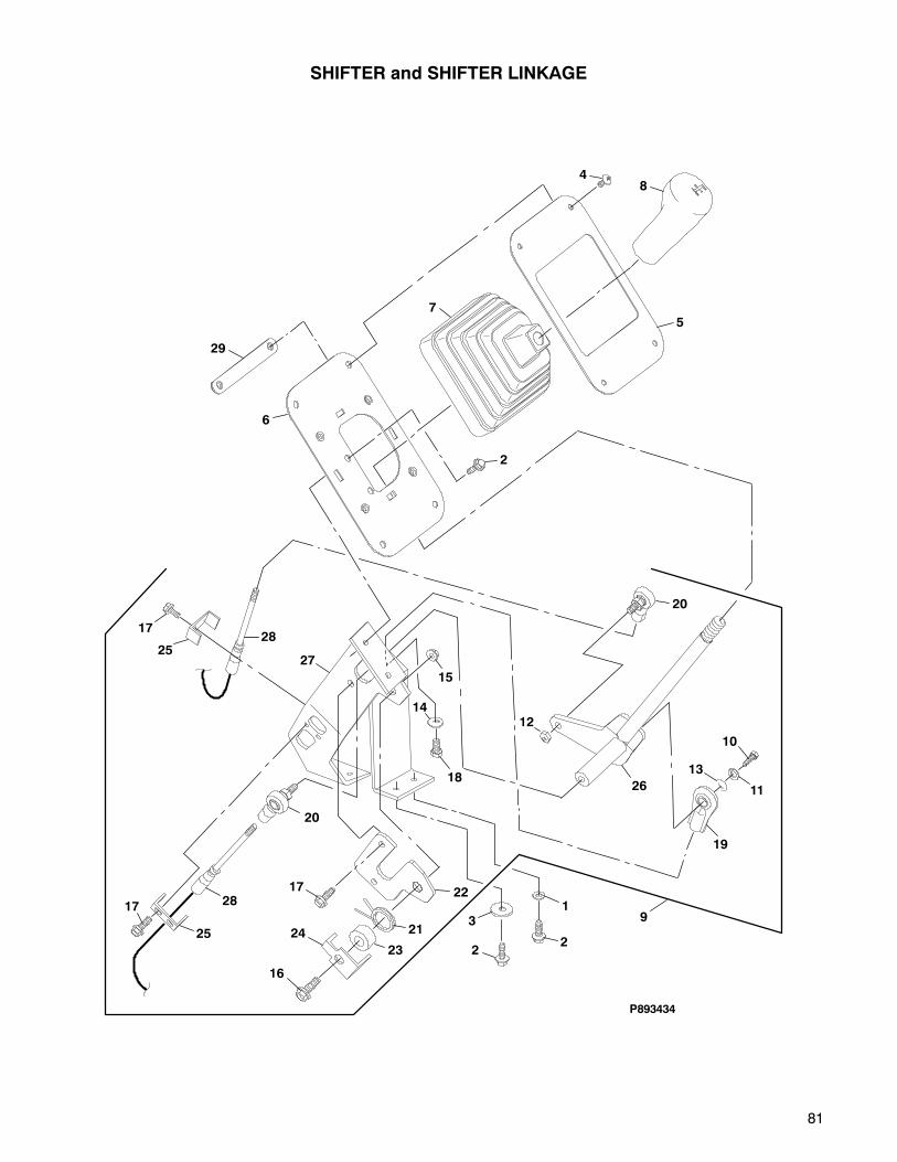
81
SHIFTER and SHIFTER LINKAGE
P893434
48
57
2
6
1
22
3 9
19
11
13
10
26
12
20
17
2528
27
15
14
18
20
28
25
17
17
16
24 21
22
23
29
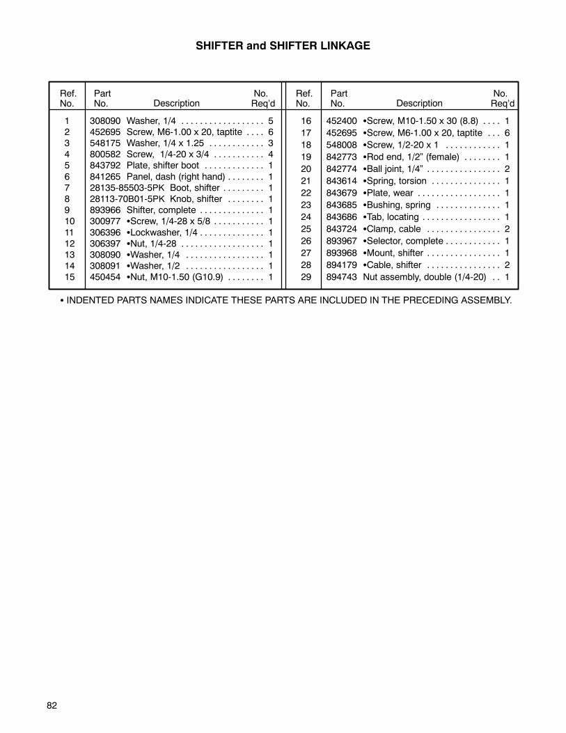
82
1 308090 Washer, 1/4 5. . . . . . . . . . . . . . . . . .2 452695 Screw, M6-1.00 x 20, taptite 6. . . .3 548175 Washer, 1/4 x 1.25 3. . . . . . . . . . . .4 800582 Screw, 1/4-20 x 3/4 4. . . . . . . . . . .5 843792 Plate, shifter boot 1. . . . . . . . . . . . .
6 841265 Panel, dash (right hand) 1. . . . . . . .7 28135-85503-5PK Boot, shifter 1. . . . . . . . .8 28113-70B01-5PK Knob, shifter 1. . . . . . . .9 893966 Shifter, complete 1. . . . . . . . . . . . . .10 300977 Screw, 1/4-28 x 5/8 1. . . . . . . . . . .
11 306396 Lockwasher, 1/4 1. . . . . . . . . . . . . .12 306397 Nut, 1/4-28 1. . . . . . . . . . . . . . . . . .13 308090 Washer, 1/4 1. . . . . . . . . . . . . . . . .14 308091 Washer, 1/2 1. . . . . . . . . . . . . . . . .15 450454 Nut, M10-1.50 (G10.9) 1. . . . . . . .
16 452400 Screw, M10-1.50 x 30 (8.8) 1. . . .
17 452695 Screw, M6-1.00 x 20, taptite 6. . .
18 548008 Screw, 1/2-20 x 1 1. . . . . . . . . . . .
19 842773 Rod end, 1/2” (female) 1. . . . . . . .
20 842774 Ball joint, 1/4” 2. . . . . . . . . . . . . . . .
21 843614 Spring, torsion 1. . . . . . . . . . . . . . .
22 843679 Plate, wear 1. . . . . . . . . . . . . . . . . .
23 843685 Bushing, spring 1. . . . . . . . . . . . . .
24 843686 Tab, locating 1. . . . . . . . . . . . . . . . .
25 843724 Clamp, cable 2. . . . . . . . . . . . . . . .
26 893967 Selector, complete 1. . . . . . . . . . . .
27 893968 Mount, shifter 1. . . . . . . . . . . . . . . .
28 894179 Cable, shifter 2. . . . . . . . . . . . . . . .
29 894743 Nut assembly, double (1/4-20) 1. .
Ref.No.
PartNo. Description
No.Req’d
No.Req’dDescription
PartNo.
Ref.No.
INDENTED PARTS NAMES INDICATE THESE PARTS ARE INCLUDED IN THE PRECEDING ASSEMBLY.
SHIFTER and SHIFTER LINKAGE
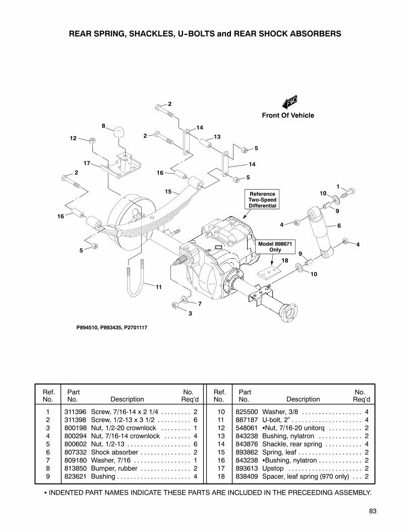
83
REAR SPRING, SHACKLES, U--BOLTS and REAR SHOCK ABSORBERS
1 311396 Screw, 7/16-14 x 2 1/4 2. . . . . . . . .2 311398 Screw, 1/2-13 x 3 1/2 6. . . . . . . . . .3 800198 Nut, 1/2-20 crownlock 1. . . . . . . . .4 800294 Nut, 7/16-14 crownlock 4. . . . . . . .5 800602 Nut, 1/2-13 6. . . . . . . . . . . . . . . . . . .
6 807332 Shock absorber 2. . . . . . . . . . . . . . .7 809180 Washer, 7/16 1. . . . . . . . . . . . . . . . .8 813850 Bumper, rubber 2. . . . . . . . . . . . . . .9 823621 Bushing 4. . . . . . . . . . . . . . . . . . . . . .
10 825500 Washer, 3/8 4. . . . . . . . . . . . . . . . . .11 887187 U-bolt, 2” 4. . . . . . . . . . . . . . . . . . . . .12 548061 Nut, 7/16-20 unitorq 2. . . . . . . . . .13 843238 Bushing, nylatron 2. . . . . . . . . . . . .14 843876 Shackle, rear spring 4. . . . . . . . . . .
15 893862 Spring, leaf 2. . . . . . . . . . . . . . . . . . .16 843238 Bushing, nylatron 2. . . . . . . . . . . . .17 893613 Upstop 2. . . . . . . . . . . . . . . . . . . . . .18 838409 Spacer, leaf spring (970 only) 2. . .
Ref.No.
PartNo. Description
No.Req’d
No.Req’dDescription
PartNo.
Ref.No.
INDENTED PART NAMES INDICATE THESE PARTS ARE INCLUDED IN THE PRECEEDING ASSEMBLY.
P894510, P893435, P2701117
2
2
12
8
17
14
13
14
5
110
7
3
11
5
16
16
15
6
4
4
9
10
5
ReferenceTwo-SpeedDifferential
2
9
18
Model 898671Only
Front Of Vehicle
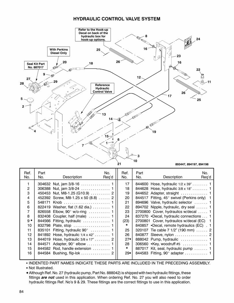
84
16
17
16
8
12
23
22
11
25
26
26
25
1 304632 Nut, jam 3/8-16 1. . . . . . . . . . . . . . .2 306388 Nut, jam 3/8-24 1. . . . . . . . . . . . . . .3 450453 Nut, M8-1.25 (G10.9) 2. . . . . . . . . .4 452392 Screw, M8-1.25 x 50 (8.8) 2. . . . . .5 548171 Knob 1. . . . . . . . . . . . . . . . . . . . . . . .
6 822419 Washer, flat (1.62 dia.) 1. . . . . . . . .7 826558 Elbow, 90 w/o-ring 1. . . . . . . . . . .8 832408 Coupler, half (male) 1. . . . . . . . . . .9 844566 Fitting, hydraulic 1. . . . . . . . . . . . . .10 832798 Plate, stop 1. . . . . . . . . . . . . . . . . . .
11 835101 Fitting, hydraulic 90 1. . . . . . . . . .12 841892 Hose, hydraulic 1/4 x 42” 1. . . . . . . .13 844019 Hose, hydraulic 3/8 x 17” 2. . . . . . . .14 844571 Adapter, 90 elbow 1. . . . . . . . . . . .15 844582 Rod, handle extension 1. . . . . . . . .16 844584 Bushing, flip-lok 2. . . . . . . . . . . . . . .
17 844600 Hose, hydraulic 1/2 x 39” 1. . . . . . . .18 844628 Hose, hydraulic 3/8 x 18” 1. . . . . . . .19 844652 Adapter, straight 1. . . . . . . . . . . . . .20 844517 Fitting, 45 swivel (Perkins only) 121 894696 Valve, hydraulic selector 1. . . . . . .
22 894702 Nipple, hydraulic, dry seal 1. . . . . .23 2700800 Cover, hydraulics w/decal 1. . . . .24 837270 Decal, hydraulic connections 1. . .
2700801 Cover, hydraulics w/decal (EC) 1840857 Decal, remote hydraulics (EC) 1.
25 320107 Tie cable 7 1/2” (190 mm) 2. . . . . .26 840877 Sleeve, nylon 2. . . . . . . . . . . . . . . . .27 888042 Pump, hydraulic 1. . . . . . . . . . . . . .28 306560 Key, woodruff #5 1. . . . . . . . . . . . .
887017 Kit, seal, hydraulic pump 1. . . . . . .29 844583 Fitting, 90 adapter 1. . . . . . . . . . . .
Ref.No.
PartNo. Description
No.Req’d
No.Req’dDescription
PartNo.
Ref.No.
HYDRAULIC CONTROL VALVE SYSTEM
ReferenceHydraulic
Control Valve
1
2
3
1021
4
7
27
9
18
615
13
5
14
19
Seal Kit PartNo. 887017
*
Refer to the Hook-upDecal on back of thehydraulic box forhook-up options. 24
893447, 894197, 894198
20
With PerkinsDiesel Only
INDENTED PART NAMES INDICATE THESE PARTS ARE INCLUDED IN THE PRECEDING ASSEMBLY.
Not Illustrated.*
2829
AlthoughRef. No. 27 (hydraulic pump, Part No. 888042) is shippedwith twohydraulic fittings, thesefittings are not used in this application. When ordering Ref. No. 27 you will also need to orderhydraulic fittings Ref. No’s 9 & 29. These fittings are the correct fittings to use in this application.
*(23)

85
HYDRAULIC LIFT SYSTEM
1 452378 Screw, M6-1.00 x 20 2. . . . . . . . . . .2 450452 Nut, M6-1.00 (G10.9) 2. . . . . . . . . .3 450453 Nut, M8-1.25 (G10.9) 4. . . . . . . . . .4 800930 Screw, M8-1.25 x 16 (8.8) 8. . . . . .5 823119 Adapter, 90 1. . . . . . . . . . . . . . . . .
6 882993 Cylinder, lift 1. . . . . . . . . . . . . . . . . .7 809265 Pin, hair 4. . . . . . . . . . . . . . . . . . . . .8 830810 Pin, clevis 2. . . . . . . . . . . . . . . . . . .
883236 Kit, seal 1. . . . . . . . . . . . . . . . . . . . .884574 Kit, seal 1. . . . . . . . . . . . . . . . . . . . .
886001 Kit, seal 1. . . . . . . . . . . . . . . . . . . . .
9 832408 Coupler half, male 1. . . . . . . . . . . . .10 832409 Coupler half, female 2. . . . . . . . . . .11 832414 Ring, retaining 4. . . . . . . . . . . . . . . .12 835101 Fitting, hydraulic 90 2. . . . . . . . . .13 832900 Hose, hydraulic, 1/4 x 38” 2. . . . . .
14 844051 Plate, float latch 1. . . . . . . . . . . . . . .15 821893 Trim, push-on As Req’d.. . . . . . . . . .16 844598 Hose, hydraulic, 1/4 x 30” 1. . . . . .17 817320 Clamp, hose 2. . . . . . . . . . . . . . . . . .18 320107 Tie, cable 7 1/2” (190 mm) 2. . . . .
19 840877 Sleeve, nylon 1. . . . . . . . . . . . . . . . .
Ref.No.
PartNo. Description
No.Req’d
No.Req’dDescription
PartNo.
Ref.No.
1
7
7
7
7
8
8 5
13
4
4
3
16
9
11
11
11
11
1010
12
12
6
2
2
14
17
ReferenceHydraulic Control
Valve
893447
1819
15
15
1
17
INDENTED PART NAMES INDICATE THESE PARTS ARE INCLUDED IN THE PRECEDING ASSEMBLY.
Not Illustrated.*
*
**
Seal Kits 883236,884574 & 886001

86
1 103867 Washer, 5/16 1. . . . . . . . . . . . . . . . .2 306328 Pin, cotter 3/32 x 3/4 1. . . . . . . . . .3 306375 Nut, 1/4-20 4. . . . . . . . . . . . . . . . . . .4 306396 Lockwasher, 1/4 4. . . . . . . . . . . . . .5 306463 Pin, cotter 1/16 x 1/2 1. . . . . . . . . .
6 308089 Washer, #10 1. . . . . . . . . . . . . . . . . .7 316907 Screw, 1/4-20 x 2 3/4 4. . . . . . . . . .8 450454 Nut, M10-1.50 (G10.9) 1. . . . . . . . .9 452404 Screw, M10-1.50 x 70 (8.8) 1. . . . .10 521144 Cover, handle 1. . . . . . . . . . . . . . . .
11 814079 Pin, clevis 5/16 x 1 1/8 1. . . . . . . . .
12 823118 Fitting, hydraulic straight 1. . . . . . .13 823225 Pin, clevis 3/16 x 1 1. . . . . . . . . . . .14 825538 Spring, compression 1. . . . . . . . . . .15 844454 Elbow, 90 w/o-ring 2. . . . . . . . . . .16 828056 Fitting 1. . . . . . . . . . . . . . . . . . . . . . .
17 828057 Fitting 1. . . . . . . . . . . . . . . . . . . . . . .18 839213 Connector, valve 1. . . . . . . . . . . . . .19 843355 Mount, control valve 1. . . . . . . . . . .20 843758 Handle, control valve 1. . . . . . . . . .21 843759 Bushing, control valve 1. . . . . . . . .
22 886270 Valve, hydraulic 1. . . . . . . . . . . . . . .
Ref.No.
PartNo. Description
No.Req’d
No.Req’dDescription
PartNo.
Ref.No.
HYDRAULIC CONTROL VALVE
894233
1
2
10
20
11
13
18
6
5
17
16
7
1522
15
9
19
4 3
814
21

87
HYDRAULIC FILTER and RESERVOIR
1 523768 Adapter, 90 elbow 1. . . . . . . . . . . .
2 548827 Screw, 1/4-20 x 1/2 2. . . . . . . . . . . .
3 844583 Fitting, 90 adapter 1. . . . . . . . . . . .
4 827486 Valve, pressure relief 1. . . . . . . . . .
5 832414 Ring, retaining 2. . . . . . . . . . . . . . . .
6 835101 Fitting, hydraulic 90 1. . . . . . . . . .
7 836206 Clamp, hose 4. . . . . . . . . . . . . . . . . .
8 844564 Hose, hydraulic, 1” x 26” 1. . . . . . .
9 844565 Hose, hydraulic, 3/4” x 16” 1. . . . .
10 844590 Adapter, straight 1. . . . . . . . . . . . . .
11 844600 Hose, hydraulic, 1/2” x 39” 1. . . . .
12 844627 Fitting, swivel tee 1. . . . . . . . . . . . .
13 844630 Hose, hydraulic, 3/8 x 21” 1. . . . . .
14 885249 Element, filter 1. . . . . . . . . . . . . . . . .
15 844973 Bushing 1. . . . . . . . . . . . . . . . . . . . . .
16 893539 Dipstick, hydraulic tank 1. . . . . . . .
17 2700800 Cover, hydraulics w/decal 1. . . . .837270 Decal, hydraulic connections 1. .2700801 Cover, hydraulics w/decal 1. . . . .840857 Decal, hydraulic connections 1. .
18 894675 Tank, hydraulic 1. . . . . . . . . . . . . . .
19 894691 Head, filter 1. . . . . . . . . . . . . . . . . . .20 894701 Coupler, hydraulic dryseal 1. . . . . .21 450453 Nut, M8-1.25 (G10.9) 2. . . . . . . . . .22 452388 Screw, M8-1.25 x 20 (G8.8) 2. . . .23 452399 Screw, M10-1.50 x 25 (8.8) 2. . . . .
24 800113 Plug 2. . . . . . . . . . . . . . . . . . . . . . . . .25 450452 Nut, M6-1.00 (10.9) 2. . . . . . . . . . . .26 452381 Screw, M6-1.00 x 40 (8.8) 2. . . . . .27 844937 Plate, coupler retainer 1. . . . . . . . .28 888042 Pump, hydraulic 1. . . . . . . . . . . . . .29 306560 Key, woodruff #5 1. . . . . . . . . . . . .
887017 Kit, seal, hydraulic pump 1. . . . . . .
Ref.No.
PartNo. Description
No.Req’d
No.Req’dDescription
PartNo.
Ref.No.
ReferenceHydraulic ControlValve And Control
Panel
893447, 894197, 894198
Seal Kit PartNo. 887017
*
283
7
8
13
12
10
14
2
19
1
7
9
7
7
11
6
5 20
5
17
4
16
18
23
22
24
24
21
25
262715
*
INDENTED PART NAMES INDICATE THESE PARTS ARE INCLUDED IN THE PRECEDING ASSEMBLY.
Not Illustrated.*
29
*
(17)

88
HAND CONTROLS, GOVERNOR and THROTTLE (GASOLINE)
ReferenceControl Panel
ReferenceFoot Throttle
Reference Differential(11.16:1 & 14.21:1)
Apply Loctite 242*
23
1 111898 Clamp, cable 2. . . . . . . . . . . . . . . . .2 120052 Lockwasher, #10 6. . . . . . . . . . . . . .3 132520 Nut, #10-32 2. . . . . . . . . . . . . . . . . .4 306328 Pin, cotter 29/32 x 3/4 1. . . . . . . . .5 306514 Screw, #10-32 x 1/2 2. . . . . . . . . . .
6 306531 Nut, #10-24 5. . . . . . . . . . . . . . . . . .7 320107 Tie, cable 7 1/2 ” (190.5 mm) 1. . .8 450452 Nut, M6-1.00 (G10.9) 1. . . . . . . . . .9 452378 Screw, M6-1.00 x 20 1. . . . . . . . . . .10 800271 Screw, #10-24 x 1/2 (G5) 4. . . . . . .
11 800582 Screw, 1/4-20 x 3/4 4. . . . . . . . . . . .12 806703 Pin, clevis 5/16 x 31/32 1. . . . . . . .
13 817104 Stop, wire 2. . . . . . . . . . . . . . . . . . . .14 827821 Knob 2. . . . . . . . . . . . . . . . . . . . . . . .15 828049 Cable, control (hand throttle) 1. . . .16 837043 Bracket (cable to differential) 1. . . .17 841264 Panel, left hand (turf) 1. . . . . . . . . .
18 843607 Bushing, throttle cable 1. . . . . . . . .19 844116 Decal, left hand dash (turf) 1. . . . .20 844130 Cable, governor control 1. . . . . . . .21 893067 Cable, control (hi-lo shift) 1. . . . . . .22 894743 Nut, double 2. . . . . . . . . . . . . . . . . . .
23 307776 Screw, 3/8-16 x 2 3/4 2. . . . . . . . . .24 836841 Bracket, hi-lo shift cable mount 1.
Ref.No.
PartNo. Description
No.Req’d
No.Req’dDescription
PartNo.
Ref.No.
11 10
14
19
17
20
222
6
15
12
16
8
21
4
9
7
62
1
5
1318
Must Attach Control Cable ToPark Brake Cable w/Cable TieTo Avoid Coming In Contact
With The Muffler
893439
24
ReferenceGovernor
3*
13
1
25
3*

89
1
HAND CONTROLS, GOVERNOR and THROTTLE (DIESEL)
ReferenceControl Panel
ReferenceFoot Throttle
Reference Differential(11.16:1 & 14.21:1)
APPLY LOCTITE 242*
26
1 111898 Clamp, cable 3. . . . . . . . . . . . . . . . .2 120052 Lockwasher, #10 6. . . . . . . . . . . . . .3 132520 Nut, #10-32 3. . . . . . . . . . . . . . . . . .4 306328 Pin, cotter 29/32 x 3/4 1. . . . . . . . .5 306514 Screw, #10-32 x 1/2 3. . . . . . . . . . .6 306531 Nut, #10-24 6. . . . . . . . . . . . . . . . . .7 320107 Tie, cable 7 1/2 ” (190.5 mm) 1. . .8 450452 Nut, M6-1.00 (G10.9) 1. . . . . . . . . .9 452378 Screw, M6-1.00 x 20 1. . . . . . . . . . .10 800271 Screw, #10-24 x 1/2 (G5) 4. . . . . . .11 800582 Screw, 1/4-20 x 3/4 4. . . . . . . . . . . .12 806703 Pin, clevis 5/16 x 31/32 1. . . . . . . .13 817104 Stop, wire 2. . . . . . . . . . . . . . . . . . . .14 827821 Knob 2. . . . . . . . . . . . . . . . . . . . . . . .15 828049 Cable, control (hand throttle) 1. . . .16 831888 Swivel 1. . . . . . . . . . . . . . . . . . . . . . .17 831889 Washer, swivel 1. . . . . . . . . . . . . . . .18 831890 Screw, swivel throttle cable 1. . . . .19 837043 Bracket 1. . . . . . . . . . . . . . . . . . . . . .
20 841264 Panel, left hand, turf 1. . . . . . . . . . .21 843607 Bushing, throttle cable 1. . . . . . . . .22 844116 Decal, left hand dash, turf 1. . . . . .23 844130 Cable, governor control 1. . . . . . . .24 893067 Cable, control (hi-lo shift) 1. . . . . . .25 894743 Nut, double 2. . . . . . . . . . . . . . . . . . .26 307776 Screw, 3/8-16 x 2 3/4 2. . . . . . . . . .27 836841 Bracket, hi-lo shift cable mount 1.28 103867 Washer, 5/16 1. . . . . . . . . . . . . . . . .29 130728 Nut, 1/4-20 jam 1. . . . . . . . . . . . . . .30 450453 Nut, M8-1.25 (G10.9) 2. . . . . . . . . .31 452394 Screw, M8-1.25 x 70 (G8.8) 2. . . .32 812444 Pin, clevis 5/16 x 3/4 1. . . . . . . . . .33 821164 Pin, hair 1. . . . . . . . . . . . . . . . . . . . .34 835271 Nut 1. . . . . . . . . . . . . . . . . . . . . . . . . .35 840473 Spring, extension 1. . . . . . . . . . . . .36 842785 Spring, idle return 1. . . . . . . . . . . . .37 844274 Lever, governor 1. . . . . . . . . . . . . . .38 894591 Bracket, throttle 1. . . . . . . . . . . . . . .
Ref.No.
PartNo. Description
No.Req’d
No.Req’dDescription
PartNo.
Ref.No.
11 10
14
22
20
23
25 15
12
19
3
8
24
4
9
7
62
5
13
21
*
Must Attach Control CableTo Park Brake Cable w/
Cable Tie To Avoid ComingIn Contact With The Muffler
894198, P894647, 893594, 893533
27
3 *
ReferenceFrom Engine
52
1
38
30
28
34
1617
1837
35
2
6 29
32
36
33
31
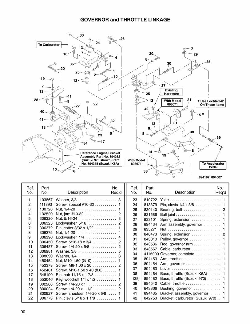
90
GOVERNOR and THROTTLE LINKAGE
1 103867 Washer, 3/8 3. . . . . . . . . . . . . . . . . . . .2 111893 Screw, special #10-32 1. . . . . . . . . . .
3 130728 Nut, 1/4-20 1. . . . . . . . . . . . . . . . . . . .
4 132520 Nut, jam #10-32 2. . . . . . . . . . . . . . . .5 306320 Nut, 5/16-24 3. . . . . . . . . . . . . . . . . . .
6 306325 Lockwasher, 5/16 2. . . . . . . . . . . . . . .
7 306372 Pin, cotter 3/32 x 1/2” 1. . . . . . . . . . .8 306375 Nut, 1/4-20 4. . . . . . . . . . . . . . . . . . . .
9 306396 Lockwasher, 1/4 4. . . . . . . . . . . . . . . .
10 306450 Screw, 5/16-18 x 3/4 2. . . . . . . . . . . .11 306487 Screw, 1/4-20 x 5/8 2. . . . . . . . . . . . .
12 306981 Washer, 3/8 5. . . . . . . . . . . . . . . . . . . .
13 308090 Washer, 1/4 3. . . . . . . . . . . . . . . . . . . .14 450454 Nut, M10-1.50 (G10) 1. . . . . . . . . . . .
15 452378 Screw, M6-1.00 x 20 2. . . . . . . . . . . .
16 452401 Screw, M10-1.50 x 40 (8.8) 1. . . . . .17 548190 Pin, hair 11/16 x 1 7/8 1. . . . . . . . . . .
18 553046 Key, woodruff 1/4 x 1/2 1. . . . . . . . . .
19 302288 Screw, 1/4-20 x 1 2. . . . . . . . . . . . . . .
20 800024 Screw, 1/4-20 x 1 1/2 2. . . . . . . . . . .21 800927 Screw, shoulder, 1/4-20 x 5/8 1. . . .
22 806773 Pin, clevis 5/16 x 1 1/8 1. . . . . . . . . .
23 810722 Yoke 1. . . . . . . . . . . . . . . . . . . . . . . . . .
24 813379 Pin, clevis 1/4 x 3/8 1. . . . . . . . . . . . .
25 830140 Bearing, ball 2. . . . . . . . . . . . . . . . . . .
26 831586 Ball joint 1. . . . . . . . . . . . . . . . . . . . . . .
27 833101 Spring, extension 1. . . . . . . . . . . . . . .
28 894434 Arm assembly, governor 1. . . . . . . . .
29 835271 Nut 1. . . . . . . . . . . . . . . . . . . . . . . . . . .
30 840473 Spring, extension 2. . . . . . . . . . . . . . .
31 843013 Pulley, governor 1. . . . . . . . . . . . . . . .
32 843536 Rod, governor arm 1. . . . . . . . . . . . . .
33 843567 Cable, carburetor 1. . . . . . . . . . . . . . .
34 4115000 Governor, complete 1. . . . . . . . . . . . .
35 894453 Arm, throttle 1. . . . . . . . . . . . . . . . . . .
36 894454 Arm, governor 1. . . . . . . . . . . . . . . . . .
37 894463 Lever 1. . . . . . . . . . . . . . . . . . . . . . . . .
38 894464 Base, throttle (Suzuki K6A) 1. . . . . .
(38) 894482 Base, throttle (Suzuki 970) 1. . . . . . .
39 894540 Cable, throttle 1. . . . . . . . . . . . . . . . . .
40 843866 Bushing, governor 1. . . . . . . . . . . . . .
41 894435 Bracket assembly, governor 1. . . . . .
42 842753 Bracket, carburetor (Suzuki 970) 1. .
Ref.No.
PartNo. Description
No.Req’d
No.Req’dDescription
PartNo.
Ref.No.
Reference Engine BracketAssembly Part No. 894362(Suzuki 970 shown) PartNo. 894375 (Suzuki K6A)
894197, 894507
To Carburetor
Use Loctite 242On These Items*
33
2426
4
4
16
13
7
36
25
12
5
2 30
11
9
18
2722
532
51
1734
10 16
20
8
3
29
3530
28
23
19
9
13
40
41
With Model898671
ExistingHardware
To AcceleratorPedal
8
20
25
12
37
21
15
42
13
9
8
31
*
38
39
81419
38
With Model898671
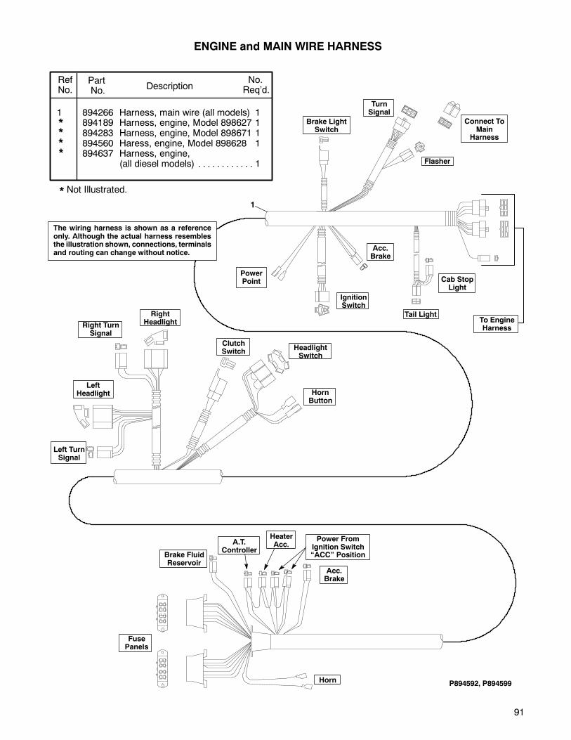
91
15
15
15
15
10
10
30
10
1 894266 Harness, main wire (all models) 1894189 Harness, engine, Model 898627 1894283 Harness, engine, Model 898671 1894560 Haress, engine, Model 898628 1894637 Harness, engine,
(all diesel models) 1. . . . . . . . . . . .
RefNo.
PartNo. Description
No.Req’d.
ENGINE and MAIN WIRE HARNESS
TurnSignal
Brake LightSwitch
Flasher
Connect ToMain
Harness
PowerPoint
IgnitionSwitch
Acc.Brake
Tail Light
Cab StopLight
RightHeadlightRight Turn
Signal
Left TurnSignal
LeftHeadlight
ClutchSwitch
HeadlightSwitch
HornButton
Horn
Acc.Brake
Brake FluidReservoir
FusePanels
P894592, P894599
A.T.Controller
HeaterAcc.
Power FromIgnition Switch“ACC” Position
To EngineHarness
1
*
**
* Not Illustrated.
The wiring harness is shown as a referenceonly. Although the actual harness resemblesthe illustration shown, connections, terminalsand routing can change without notice.
*
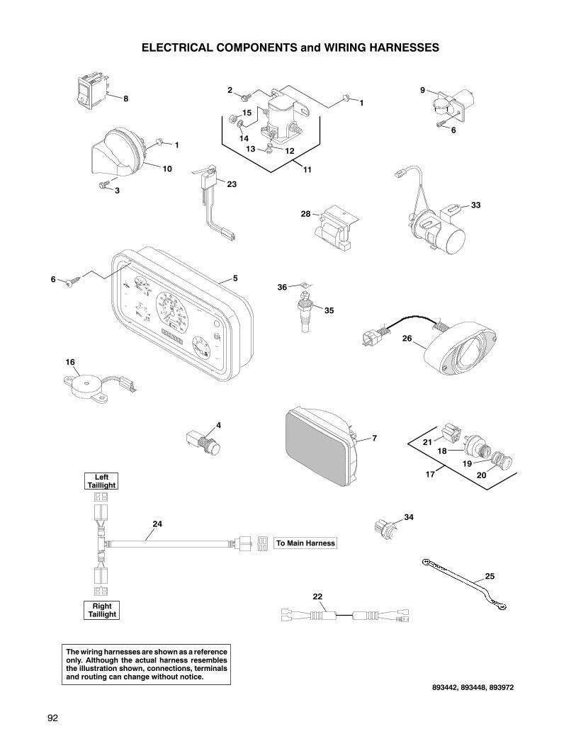
92
ELECTRICAL COMPONENTS and WIRING HARNESSES
LeftTaillight
To Main Harness
RightTaillight
Thewiring harnesses are shownas a referenceonly. Although the actual harness resemblesthe illustration shown, connections, terminalsand routing can change without notice.
1
11
2
14
15
1213
9
6
8
23
10
3
1
4
16
7
17
18
19
20
21
22
24
893442, 893448, 893972
33
34
35
36
25
6 5
28
26

93
1 450452 Nut, M6-1.00 (G10) 3. . . . . . . . . . .2 452378 Screw, M6-1.00 x 20 2. . . . . . . . . .3 800934 Screw, M6-1.00 x 16 (G10) 1. . . . .4 830366 Switch, push (horn button) 1. . . . .5 841636 Panel, instrument w/tach 1. . . . . . .6 800943 Screw, #10-14 x 5/8 4. . . . . . . . . . .7 837303 Headlight, rectangular 2. . . . . . . . .8 843581 Switch, headlight 1. . . . . . . . . . . . .9 843942 Socket, 12V acc. plug 1. . . . . . . . .10 886090 Horn 1. . . . . . . . . . . . . . . . . . . . . . . .11 889673 Solenoid 1. . . . . . . . . . . . . . . . . . . . .12 120052 SLockwasher, #10 2. . . . . . . . . . . . .13 132520 SNut, #10-32 2. . . . . . . . . . . . . . . . .14 306325 SLockwasher, 5/16 2. . . . . . . . . . . .15 306932 SNut, 5/16-18 2. . . . . . . . . . . . . . . . .16 890000 Buzzer assembly 1. . . . . . . . . . . . .17 890154 Switch, ignition, complete 1. . . . . .18 837295 SSwitch, ignition 1. . . . . . . . . . . . . .
837296 SConnector 1. . . . . . . . . . . . . . . . . .19 837299 SSpacer 1. . . . . . . . . . . . . . . . . . . . .
20 837300 SSpacer 1. . . . . . . . . . . . . . . . . . . . .21 890158 SConnector and wire 1. . . . . . . . . .22 894201 Harness, wire, fuel tank 1. . . . . . . .23 894308 Switch (normally open) 1. . . . . . . .24 894313 Harness, wire, taillight 1. . . . . . . . .25 39312-50F01 Wire, noise suppressor
(Suzuki Models Only) 1. . . . .26 893602 Taillight 1. . . . . . . . . . . . . . . . . . . . . .27 894531 Harness, ATM controller
(Model 898628) 1. . . . . . . . . . . . . . .28 33410-50F20 Coil, ignition (Suzuki K6A) 129 18570-84000 Switch set, vacuum 1. . . . . .30 38850-51F10 Controller, idle up 1. . . . . . . .31 38850-50F41 Controller, fuel 1. . . . . . . . . . .32 38880-51F13 Controller, auto. trans. 1. . . .33 33410-85010 Coil, ignition (Suzuki 970) 1.34 17680-50F70 Switch, fan 1. . . . . . . . . . . . . .35 843857 Sender, water temperature 1. . . . .36 829787 Terminal, 45_ 1/4” male 1. . . . . . . .
Ref. Part No.No. No. Description Req’d.
Ref. Part No.No. No. Description Req’d.
S INDENTED PARTS NAMES INDICATE THESE PARTS ARE INCLUDED IN THE PRECEDING ASSEMBLY.
ELECTRICAL COMPONENTS and WIRING HARNESSES
Not Illustrated*
*
ToController
To Main HarnessPower Ground
To ShifterLight
To Accessory(Idle Up)
ToEngine Harness
27
The itemsshownon this page areusedwith the auromatic transmission onvehicle Model 898628.
The convoluted tubing used on the wiring harnesses can be ordered in bulk length only. Cut off therequired amount for your particular application. Order the tubing as follows:
Part No. 826190 .350 i.d. sold in 50’ (15.2 m) lengths
Part No. 826191 .500 i.d. sold in 25’ (7.6 m) lengths
31
30
29
32
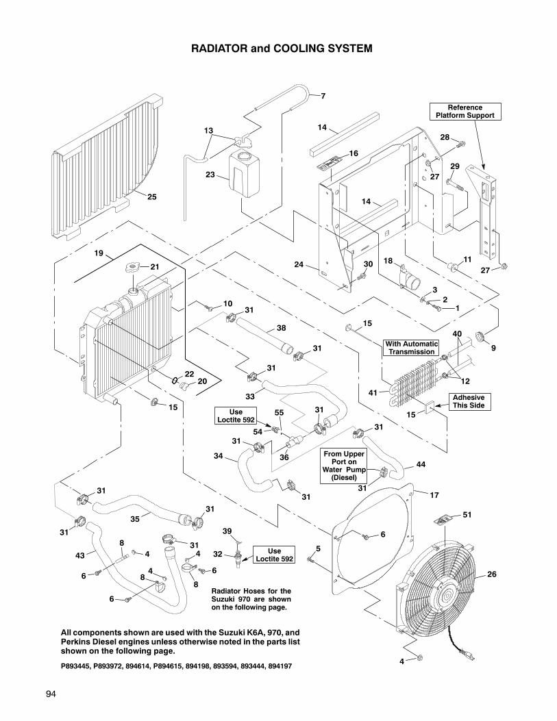
94
ReferencePlatform Support
25
7
13
23
14
16
24
14
28
27
29
27
11
12
3
1830
19
2022
21
5
6
17
51
4P893445, P893972, 894614, P894615, 894198, 893594, 893444, 894197
10
RADIATOR and COOLING SYSTEM
31
35
31
31
31
31
34
31
33
54
32 UseLoctite 592
39
AdhesiveThis Side
With AutomaticTransmission
15
15
40
12
15
9
41
26
All components shown are used with the Suzuki K6A, 970, andPerkins Diesel engines unless otherwise noted in the parts listshown on the following page.
From UpperPort on
Water Pump(Diesel)
55
31
31
31
31
31
31
Radiator Hoses for theSuzuki 970 are shownon the following page.
38
43
4436
UseLoctite 592
44
4
6
66
8
88

95
1 300646 Screw, 1/4-20 x 3/4 2. . . . . . . . . . . .2 306396 Lockwasher, 1/4 2. . . . . . . . . . . . . .3 308090 Washer, 1/4 2. . . . . . . . . . . . . . . . . .4 450452 Nut, M6-1.00 7. . . . . . . . . . . . . . . . .5 450541 Screw, M6-1.00 x 16 4. . . . . . . . . . .
6 452378 Screw, M6-1.00 x 20 7. . . . . . . . . . .7 835805 Hose, radiator overflow As Req’d..8 825884 Clamp, tube 3. . . . . . . . . . . . . . . . . .9 809231 Grommet (Model 898671) 2. . . . . . .10 800177 Screw, 5/16-18 x 3/4 4. . . . . . . . . . .
11 831846 Nut, isolation 4. . . . . . . . . . . . . . . . .12 825624 Clamp, hose (Model 898671) 4. . .13 889051 Cap, coolant reservoir 1. . . . . . . . .14 833512 Foam 2. . . . . . . . . . . . . . . . . . . . . . . .15 800789 Kit, oil cooler mounting, automatic
transmission (Model 898671) 1. . .
16 840754 Decal, Warning Pressure 1. . . . . . .17 843040 Bracket, fan mounting 1. . . . . . . . .18 888549 Connector, hose (air cleaner) 1. . .19 894590 Radiator 1. . . . . . . . . . . . . . . . . . . . .20 833443 Plug 1. . . . . . . . . . . . . . . . . . . . . . . .
21 889049 Cap, radiator 1. . . . . . . . . . . . . . . .22 833442 O-ring 1. . . . . . . . . . . . . . . . . . . . . .23 889050 Reservoir, coolant 1. . . . . . . . . . . . .24 893388 Mount, radiator 1. . . . . . . . . . . . . . .25 893554 Screen 1. . . . . . . . . . . . . . . . . . . . . .
26 2700799 Fan, radiator, cooling 1. . . . . . . . .27 450453 Nut, M8-1.25 (G10.9) 2. . . . . . . . . .28 452388 Screw, M8-1.25 x 20 (8.8) 1. . . . . .29 452395 Screw, M10-1.50 x 80 (8.8) 1. . . . .
30 452398 Screw, M10-1.50 x 20 (8.8) 2. . . . .
31 820889 Clamp, tubing 6. . . . . . . . . . . . . . . .
32 843857 Sender, water temperature 1. . . . .
33 843638 Hose, radiator upper (K6A) 1. . . . .
34 843639 Hose, radiator (K6A) 1. . . . . . . . . . .
35 843646 Hose, radiator lower (K6A & 970) 1
36 894348 Tube, fan switch (K6A & Perkins) 1
37 844034 Hose, radiator upper (970) 1. . . . .
38 842746 Hose, radiator upper (Perkins) 1. .
39 829787 Terminal, 45 1/4” male 1. . . . . . . .
40 826590 Hose, 5/16 i.d.
(Model 898671) As Req’d.. . . . . . . .
41 838340 Cooler, oil
(automatic transmission) 1. . . . . . .
42 821893 Trim, push-on
(Model 898671) As Req’d.. . . . . . . .
43 844391 Hose, radiator lower (Perkins) 1. .
44 844390 Hose, radiator (Perkins) 1. . . . . . . .
45 452393 Screw, M8-1.25 x 60 (8.8) 2. . . . . .
46 832033 Clamp (970) 1. . . . . . . . . . . . . . . . . .
47 833715 Plug (970) 1. . . . . . . . . . . . . . . . . . . .
48 833858 Fitting, hose (970) 1. . . . . . . . . . . . .
49 843738 Housing, fan sender (970) 1. . . . . .
50 843856 Gasket, fan switch housing (970) 2
51 009034880 Decal, fan 1. . . . . . . . . . . . . . . .
52 17561-73000 Cap, water (970) 1. . . . . . . . .
53 17600-85831 Thermostat (970) 1. . . . . . . .
54 17680-50F70 Switch, fan 1. . . . . . . . . . . . . .
55 17689-50F00 O-ring 1. . . . . . . . . . . . . . . . .
Ref.No.
PartNo. Description
No.Req’d
No.Req’dDescription
PartNo.
Ref.No.
INDENTED PART NAMES INDICATE THESE PARTS ARE INCLUDED IN THE PRECEDING ASSEMBLY
The parts illustration only shows two (2) of Item 12 (825624HoseClamps). The other two are usedto secure the cooler hoses to the transmission lines.
Not Illustrated. Item 42 (821893 Push-on Trim) is used on Model 898671 to protect the automatictransmission hoses and is used on the right side motor mount and the frame rail.
RADIATOR and COOLING SYSTEM
3731
3531
31
31
52
50
50
55
54
47
46
4853
49
WithSuzuki 970
(Model 898671)
ReferenceRadiator
45
Use Loctite592
Use Loctite242
Use Loctite592

96
ReferenceAlternator
Part No. 893633
Use Loctite 242On These Items
ReferencePower Steering Pump
Part No. 892534
ReferenceGovernor
Part No. 894080
ReferenceFan Switch TubePart No. 894348(With Radiator)
ToEngine
ToEngine
ALTERNATOR, ENGINE BELTS, PULLEYS and BRACKETS(SUZUKI K6A)
1 103867 Washer, 3/8 3. . . . . . . . . . . . . . . . . .2 120177 Lockwasher, 3/8 2. . . . . . . . . . . . . .3 306835 Screw, 3/8-16 x 1 3/4 1. . . . . . . . . .4 306325 Lockwasher, 5/16 3. . . . . . . . . . . . .5 306375 Nut, 1/4-20 1. . . . . . . . . . . . . . . . . . .
6 306396 Lockwasher, 1/4 1. . . . . . . . . . . . . .7 306416 Screw, 5/16-18 x 1 1. . . . . . . . . . . .8 306450 Screw, 5/16-18 x 3/4 2. . . . . . . . . . .9 306562 Nut, 3/8-16 2. . . . . . . . . . . . . . . . . . .10 306981 Washer, 3/8 3. . . . . . . . . . . . . . . . . .
11 311213 Screw, 3/8-16 x 3 1. . . . . . . . . . . . .12 450453 Nut, M8-1.25 (G10.9) 5. . . . . . . . . .13 452388 Screw, M8-1.25 x 20 (8.8) 8. . . . . .14 452394 Screw, M8-1.25 x 70 (8.8) 2. . . . . .
15 844035 Pulley, 4.75” (governor) 1. . . . . . . .16 841027 V-belt, 53 1/4” (1352 mm) 1. . . . . .17 839907 Pulley, 5.50” (steering pump) 1. . .18 2703818.7 Bracket, alternator mounting 1.19 843998 V-belt, 40” (1016 mm) 1. . . . . . . . .
20 894375 Bracket, governor mounting 1. . . .21 800073 Bolt, carriage, 3/8-16 x 1 1/4 1. . . .22 828100 Pulley, 5.50” (hydraulic pump) 1. .23 548804 Nut, 3/8-16 1. . . . . . . . . . . . . . . . . . .24 12619-60B00 Bolt 1. . . . . . . . . . . . . . . . . . . .
25 95131-51F60 Pulley, crankshaft(manual transmission) 1. . . .
95131-51F50 Pulley, crankshaft(automatic transmission) 1. .
Ref.No.
PartNo. Description
No.Req’d
No.Req’dDescription
PartNo.
Ref.No.
12
17
14
13
41
2425
18
136
5
894588, 894507
P
E
EXC
BS
R
G
B
W/R
R
RB
P
E
EXC
BS
R
G
B
W/R
R
R
MODEL 898628MODEL 898627
3
2
21
23
ReferenceHydraulicPump PartNo. 888042
10
9
22
19
16
Engine Belt DiagramModels 898627 & 898628
ALTERNATOR WIRINGALT
PWRSTRNG
CRNKSHFT
GOVHYDRPUMP
ExistingHardware
From Engine
*
Front Of Vehicle
12
12
11
10
1313* 14
8
15
20
7
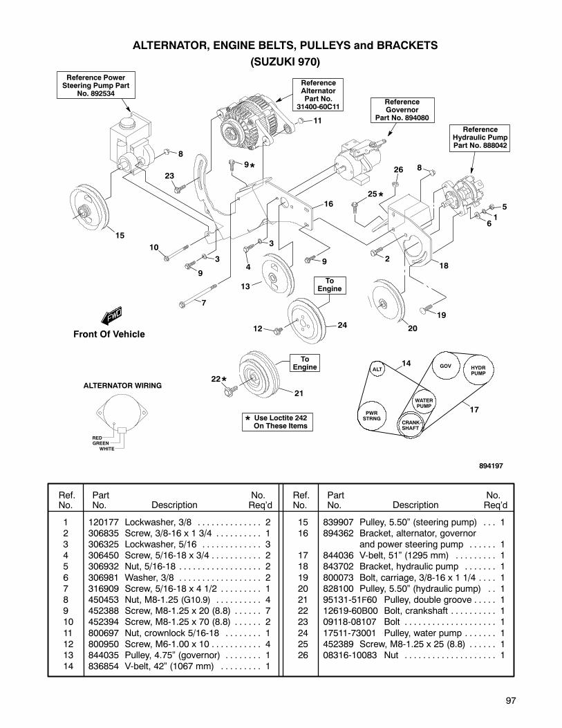
97
ReferenceAlternatorPart No.
31400-60C11
Use Loctite 242On These Items
*
Reference PowerSteering Pump Part
No. 892534ReferenceGovernor
Part No. 894080
ToEngine
ALTERNATOR, ENGINE BELTS, PULLEYS and BRACKETS
(SUZUKI 970)
1 120177 Lockwasher, 3/8 2. . . . . . . . . . . . . .2 306835 Screw, 3/8-16 x 1 3/4 1. . . . . . . . . .3 306325 Lockwasher, 5/16 3. . . . . . . . . . . . .4 306450 Screw, 5/16-18 x 3/4 2. . . . . . . . . . .5 306932 Nut, 5/16-18 2. . . . . . . . . . . . . . . . . .
6 306981 Washer, 3/8 2. . . . . . . . . . . . . . . . . .7 316909 Screw, 5/16-18 x 4 1/2 1. . . . . . . . .8 450453 Nut, M8-1.25 (G10.9) 4. . . . . . . . . .9 452388 Screw, M8-1.25 x 20 (8.8) 7. . . . . .10 452394 Screw, M8-1.25 x 70 (8.8) 2. . . . . .
11 800697 Nut, crownlock 5/16-18 1. . . . . . . .12 800950 Screw, M6-1.00 x 10 4. . . . . . . . . . .13 844035 Pulley, 4.75” (governor) 1. . . . . . . .14 836854 V-belt, 42” (1067 mm) 1. . . . . . . . .
15 839907 Pulley, 5.50” (steering pump) 1. . .16 894362 Bracket, alternator, governor
and power steering pump 1. . . . . .17 844036 V-belt, 51” (1295 mm) 1. . . . . . . . .18 843702 Bracket, hydraulic pump 1. . . . . . .
19 800073 Bolt, carriage, 3/8-16 x 1 1/4 1. . . .20 828100 Pulley, 5.50” (hydraulic pump) 1. .21 95131-51F60 Pulley, double groove 1. . . . .22 12619-60B00 Bolt, crankshaft 1. . . . . . . . . .23 09118-08107 Bolt 1. . . . . . . . . . . . . . . . . . . .
24 17511-73001 Pulley, water pump 1. . . . . . .25 452389 Screw, M8-1.25 x 25 (8.8) 1. . . . . .26 08316-10083 Nut 1. . . . . . . . . . . . . . . . . . . .
Ref.No.
PartNo. Description
No.Req’d
No.Req’dDescription
PartNo.
Ref.No.
894197
ReferenceHydraulic PumpPart No. 888042
ALTERNATOR WIRING
ALT
PWRSTRNG
CRANK-SHAFT
GOV HYDRPUMP
ToEngine
WATERPUMP
REDGREEN
WHITE
8
23
15
10
9
34
3
7
9 *
11
13
12 24
21
22
9
5
16
218
20
19
14
17
8
*
16
25 *
26
Front Of Vehicle
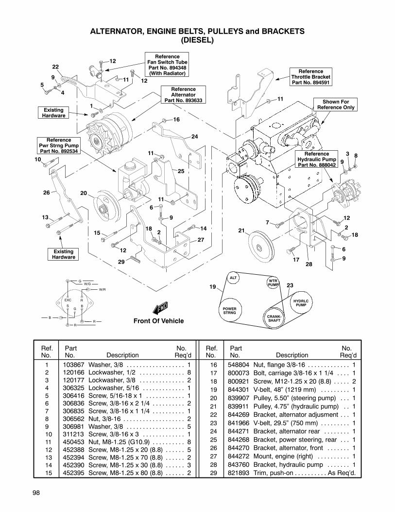
98
1 103867 Washer, 3/8 1. . . . . . . . . . . . . . . . . .2 120166 Lockwasher, 1/2 8. . . . . . . . . . . . . .3 120177 Lockwasher, 3/8 2. . . . . . . . . . . . . .4 306325 Lockwasher, 5/16 1. . . . . . . . . . . . .5 306416 Screw, 5/16-18 x 1 1. . . . . . . . . . . .6 306836 Screw, 3/8-16 x 2 1/4 2. . . . . . . . . .7 306835 Screw, 3/8-16 x 1 1/4 1. . . . . . . . . .8 306562 Nut, 3/8-16 2. . . . . . . . . . . . . . . . . . .9 306981 Washer, 3/8 5. . . . . . . . . . . . . . . . . .10 311213 Screw, 3/8-16 x 3 1. . . . . . . . . . . . .11 450453 Nut, M8-1.25 (G10.9) 8. . . . . . . . . .12 452388 Screw, M8-1.25 x 20 (8.8) 5. . . . . .13 452394 Screw, M8-1.25 x 70 (8.8) 2. . . . . .14 452390 Screw, M8-1.25 x 30 (8.8) 3. . . . . .15 452395 Screw, M8-1.25 x 80 (8.8) 2. . . . . .
16 548804 Nut, flange 3/8-16 1. . . . . . . . . . . . .
17 800073 Bolt, carriage 3/8-16 x 1 1/4 1. . . .
18 800921 Screw, M12-1.25 x 20 (8.8) 2. . . . .
19 844301 V-belt, 48” (1219 mm) 1. . . . . . . . .
20 839907 Pulley, 5.50” (steering pump) 1. . .
21 839911 Pulley, 4.75” (hydraulic pump) 1. .
22 844269 Bracket, alternator adjusment 1. . .
23 841966 V-belt, 29.5” (750 mm) 1. . . . . . . . .
24 844271 Bracket, alternator rear 1. . . . . . . .
25 844268 Bracket, power steering, rear 1. . .
26 844270 Bracket, alternator, front 1. . . . . . .
27 844272 Mount, engine (right) 1. . . . . . . . . .
28 843760 Bracket, hydraulic pump 1. . . . . . .
29 821893 Trim, push-on As Req’d.. . . . . . . . . .
Ref.No.
PartNo. Description
No.Req’d
No.Req’dDescription
PartNo.
Ref.No.
EXC
BS
R
G
B
W/R
R
W/G
G
R
ALTERNATOR, ENGINE BELTS, PULLEYS and BRACKETS(DIESEL)
ReferenceAlternator
Part No. 893633
ReferencePwr Strng PumpPart No. 892534
ReferenceHydraulic PumpPart No. 888042
POWERSTRNG
ALTWTRPUMP
HYDRLCPUMP
CRANK-SHAFT
ExistingHardware
ReferenceThrottle BracketPart No. 894591
Shown ForReference Only
ReferenceFan Switch TubePart No. 894348(With Radiator)
ExistingHardware
12
12119
4
5
1
22
10
26
13
20
15
12
29
6
9
182
14
27
11
25
11
16
24
21
7
17
6
9
2
18
12
9
3 8
28
11
19 23
Front Of Vehicle
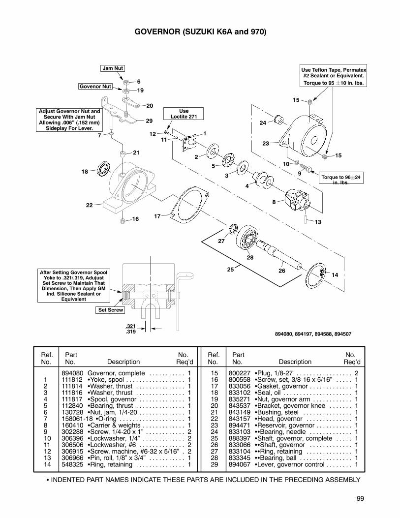
99
UseLoctite 271
Use Teflon Tape, Permatex#2 Sealant or Equivalent.
Torque to 95¦10 in. lbs.
Adjust Governor Nut andSecure With Jam Nut
Allowing .006” (.152 mm)Sideplay For Lever.
Govenor Nut
Jam Nut
GOVERNOR (SUZUKI K6A and 970)
.321
.319
Set Screw
After Setting Governor SpoolYoke to .321/.319, AdujustSet Screw to Maintain ThatDimension, Then Apply GMInd. Silicone Sealant or
Equivalent
Ref.No.
PartNo. Description
No.Req’d
No.Req’dDescription
PartNo.
Ref.No.
894080 Governor, complete 1. . . . . . . . . . .1 111812 Yoke, spool 1. . . . . . . . . . . . . . . . . .2 111814 Washer, thrust 1. . . . . . . . . . . . . . .3 111816 Washer, thrust 1. . . . . . . . . . . . . . .4 111817 Spool, governor 1. . . . . . . . . . . . . .5 112840 Bearing, thrust 1. . . . . . . . . . . . . . .6 130728 Nut, jam, 1/4-20 1. . . . . . . . . . . . . .7 158061-18 O-ring 1. . . . . . . . . . . . . . . . . . . .8 160410 Carrier & weights 1. . . . . . . . . . . . .9 302288 Screw, 1/4-20 x 1” 2. . . . . . . . . . . .10 306396 Lockwasher, 1/4” 2. . . . . . . . . . . . .11 306506 Lockwasher, #6 2. . . . . . . . . . . . . .12 306915 Screw, machine, #6-32 x 5/16” 2.13 306966 Pin, roll, 1/8” x 3/4” 1. . . . . . . . . . .14 548325 Ring, retaining 1. . . . . . . . . . . . . . .
15 800227 Plug, 1/8-27 2. . . . . . . . . . . . . . . . .16 800558 Screw, set, 3/8-16 x 5/16” 1. . . . .17 833056 Gasket, governor 1. . . . . . . . . . . . .18 833102 Seal, oil 1. . . . . . . . . . . . . . . . . . . . .19 835271 Nut, governor arm 1. . . . . . . . . . . .20 843537 Bracket, governor knee 1. . . . . . .21 843149 Bushing, steel 1. . . . . . . . . . . . . . .22 843157 Head, governor 1. . . . . . . . . . . . . .23 894471 Reservoir, governor 1. . . . . . . . . . .24 833103 Bearing, needle 1. . . . . . . . . . . . .25 888397 Shaft, governor, complete 1. . . . .26 833066 Shaft, governor 1. . . . . . . . . . . . .27 833104 Ring, retaining 1. . . . . . . . . . . . . .28 833345 Bearing, ball 1. . . . . . . . . . . . . . . .29 894067 Lever, governor control 1. . . . . . . .
INDENTED PART NAMES INDICATE THESE PARTS ARE INCLUDED IN THE PRECEDING ASSEMBLY
894080, 894197, 894588, 894507
6
19
20
29
7
21
18
22
16 17
25
27
26
28
14
13
8
4
3
5
2
11211
24
15
15
23
10
9Torque to 96¦24
in. lbs.
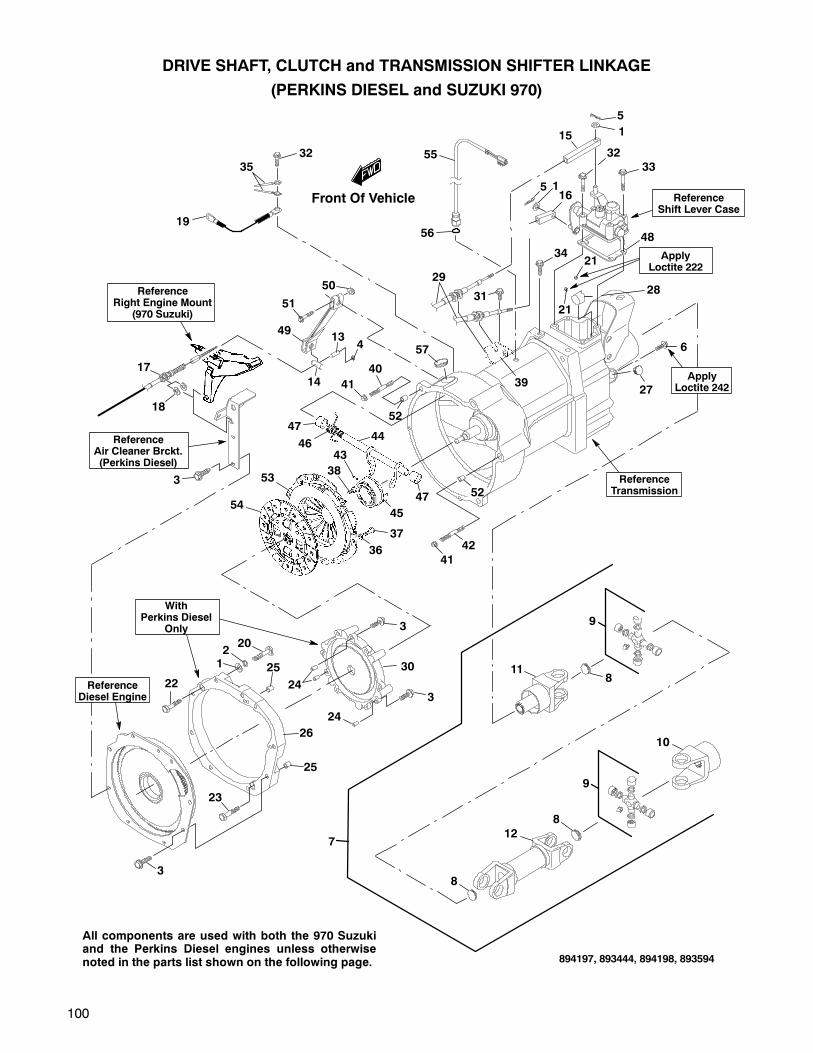
100
9
9
DRIVE SHAFT, CLUTCH and TRANSMISSION SHIFTER LINKAGE
(PERKINS DIESEL and SUZUKI 970)
WithPerkins Diesel
Only
ApplyLoctite 222
3235
19
55
56
5 116
31
34
39
57
47
47
46
53
54
43
45
44
38
36
37
41
42
52
40
41
52
49
50
51
17
18
14
134
28
27
21
21
811
12
8
8
10
3
23
25
25
26
24
24
3
3
30
2021
22
7
ReferenceShift Lever Case
ReferenceRight Engine Mount
(970 Suzuki)
ReferenceAir Cleaner Brckt.(Perkins Diesel)
ReferenceTransmission
All components are used with both the 970 Suzukiand the Perkins Diesel engines unless otherwisenoted in the parts list shown on the following page.
3
ReferenceDiesel Engine
6
ApplyLoctite 242
29
894197, 893444, 894198, 893594
48
15
5
1
3233
Front Of Vehicle

101
1 103867 Washer, 5/16 4. . . . . . . . . . . . . . . . .2 306325 Lockwasher, 5/16 2. . . . . . . . . . . . .3 452389 Screw, M8-1.25 x 25 (8.8) 11. . . . .4 450377 Nut, nylock M6-1.00 (8.8) 1. . . . . .5 548190 Hairpin 2. . . . . . . . . . . . . . . . . . . . . .
6 800934 Screw, M6-1.00 x 16 (8.8) 1. . . . . .7 894272 Driveshaft, complete 1. . . . . . . . . . .8 548482 Plug, expansion 3. . . . . . . . . . . . . .9 826284 Cross, u-joint 2. . . . . . . . . . . . . . . .10 826285 Yoke, universal 1. . . . . . . . . . . . . . .
11 894432 Yoke, front 1. . . . . . . . . . . . . . . . . .12 894433 Shaft, drive 1. . . . . . . . . . . . . . . . . .13 833273 Bushing 1. . . . . . . . . . . . . . . . . . . . . .14 842010 Bushing, clutch arm 1. . . . . . . . . . .15 843830 Connector, shift cable 1. . . . . . . . . .16 843778 Connector, shift cable 1. . . . . . . . . .
17 894299 Cable, clutch 1. . . . . . . . . . . . . . . . .18 844202 Washer, slotted 4. . . . . . . . . . . . . . .19 892811 Wire, ground, black 24” (610 mm) 120 452392 Screw, M8-1.25 x 50 (8.8) 2. . . . . .21 548222 Set screw, #8-32 2. . . . . . . . . . . . . .
22 800948 Screw, M10-1.25 x 35 (12.9) 1. . . .23 800949 Screw, M10-1.25 x 50 (12.9) 1. . . .24 839752 Pin, dowel, 8 mm x 18 mm 3. . . . .25 842961 Sleeve, alignment 2. . . . . . . . . . . . .26 843323 Adapter, transmission (Perkins) 1.
27 843754 Plug 1. . . . . . . . . . . . . . . . . . . . . . . . .28 844228 Stop, 5th gear lockout 1. . . . . . . . .29 894179 Cable, shifter 2. . . . . . . . . . . . . . . . .
30 894645 Ring, pressure plate (Perkins) 1. .31 01550-08803 Screw 1. . . . . . . . . . . . . . . . . . .32 01550-08403 Screw 4. . . . . . . . . . . . . . . . . . .33 01550-08553 Screw 1. . . . . . . . . . . . . . . . . . .34 09103-08131 Screw 1. . . . . . . . . . . . . . . . . . .
35 39312-50F01 Wire, noise suppressor 2. . . .36 08321-01083 Lockwasher 2. . . . . . . . . . . . . .37 09111-08035 Screw 2. . . . . . . . . . . . . . . . . . .38 09117-08096 Screw 4. . . . . . . . . . . . . . . . . . .39 28391-85202 Bracket, shift cables 1. . . . . .
40 01421-10403 Stud 1. . . . . . . . . . . . . . . . . . . .41 08316-10103 Nut 2. . . . . . . . . . . . . . . . . . . . .42 01421-10503 Stud 1. . . . . . . . . . . . . . . . . . . .43 09205-03019 Pin, roll 1. . . . . . . . . . . . . . . . . .44 23260-85203 Shaft, clutch release 1. . . . . .45 23265-85200 Bearing, clutch release 1. . . .
46 09448-20007 Spring, clutch release 1. . . . .47 09300-14017 Bushing, clutch release 2. . . .48 845223 Gasket, shifter case 1. . . . . . . . . . .49 23266-85002 Arm, clutch release 1. . . . . . .50 08316-10083 Nut 1. . . . . . . . . . . . . . . . . . . . .
51 01550-08353 Screw 1. . . . . . . . . . . . . . . . . . .52 04211-13149 Sleeve, alignment 2. . . . . . . .53 22100-85200 Cover assembly, clutch 1. . . .54 22400-85141 Disc, compression clutch 1. .55 37610-80023 Switch, backup lamp 1. . . . . .
56 09280-11002 O-ring 1. . . . . . . . . . . . . . . . . .57 09250-30003 Plug, transmission
inspection timing 1. . . . . . . . .
Ref.No.
PartNo. Description
No.Req’d
No.Req’dDescription
PartNo.
Ref.No.
INDENTED PART NAMES INDICATE THESE PARTS ARE INCLUDED IN THE PRECEDING ASSEMBLY
DRIVE SHAFT, CLUTCH and TRANSMISSION SHIFTER LINKAGE
(PERKINS DIESEL and SUZUKI 970)
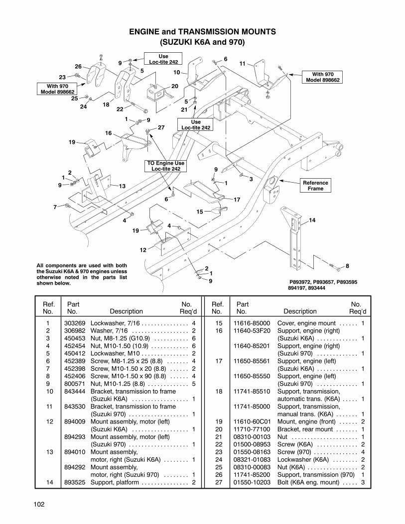
102
ReferenceFrame
P893972, P893657, P893595894197, 893444
1 303269 Lockwasher, 7/16 4. . . . . . . . . . . . . . .2 306982 Washer, 7/16 2. . . . . . . . . . . . . . . . . .
3 450453 Nut, M8-1.25 (G10.9) 6. . . . . . . . . . .
4 452454 Nut, M10-1.50 (10.9) 6. . . . . . . . . . . .5 450412 Lockwasher, M10 2. . . . . . . . . . . . . . .
6 452389 Screw, M8-1.25 x 25 (8.8) 4. . . . . . .
7 452398 Screw, M10-1.50 x 20 (8.8) 2. . . . . .8 452406 Screw, M10-1.50 x 90 (8.8) 4. . . . . .
9 800571 Nut, M10-1.25 (8.8) 5. . . . . . . . . . . . .
10 843444 Bracket, transmission to frame(Suzuki K6A) 1. . . . . . . . . . . . . . . . . .
11 843530 Bracket, transmission to frame
(Suzuki 970) 1. . . . . . . . . . . . . . . . . . .12 894009 Mount assembly, motor (left)
(Suzuki K6A) 1. . . . . . . . . . . . . . . . . .
894293 Mount assembly, motor (left)(Suzuki 970) 1. . . . . . . . . . . . . . . . . . .
13 894010 Mount assembly,
motor, right (Suzuki K6A) 1. . . . . . . .
894292 Mount assembly,motor, right (Suzuki 970) 1. . . . . . . .
14 893525 Support, platform 2. . . . . . . . . . . . . . .
15 11616-85000 Cover, engine mount 1. . . . . .16 11640-53F20 Support, engine (right)
(Suzuki K6A) 1. . . . . . . . . . . . .
11640-85201 Support, engine (right)(Suzuki 970) 1. . . . . . . . . . . . .
17 11650-85561 Support, engine (left)
(Suzuki K6A) 1. . . . . . . . . . . . .11650-85550 Support, engine (left)
(Suzuki 970) 1. . . . . . . . . . . . .
18 11741-85510 Support, transmission,automatic trans. (K6A) 1. . . . .
11741-85000 Support, transmission,
manual trans. (K6A) 1. . . . . . .19 11610-60C01 Mount, engine (front) 2. . . . . .
20 11710-77100 Bracket, rear mount 1. . . . . . .
21 08310-00103 Nut 1. . . . . . . . . . . . . . . . . . . . .22 01500-08953 Screw (K6A) 2. . . . . . . . . . . . .
23 01550-08163 Screw (970) 4. . . . . . . . . . . . . .
24 08321-01083 Lockwasher (K6A) 2. . . . . . . .
25 08310-00083 Nut (K6A) 2. . . . . . . . . . . . . . . .26 11741-85200 Support, transmission (970) 1
27 01550-10203 Bolt (K6A eng. mount) 3. . . . .
Ref.No.
PartNo. Description
No.Req’d
No.Req’dDescription
PartNo.
Ref.No.
ENGINE and TRANSMISSION MOUNTS
(SUZUKI K6A and 970)
TO Engine UseLoc-tite 242
1
1
5
1
1
2
2
44
6
27
7
8
9
9
9
10
19
16
20
17
21
12
13
14
19
15
18
UseLoc-tite 242
26
23
22
25
24
With 970Model 898662
With 970Model 898662
All components are used with boththe Suzuki K6A & 970 engines unlessotherwise noted in the parts listshown below.
UseLoc-tite 242
611
9
3
5
9
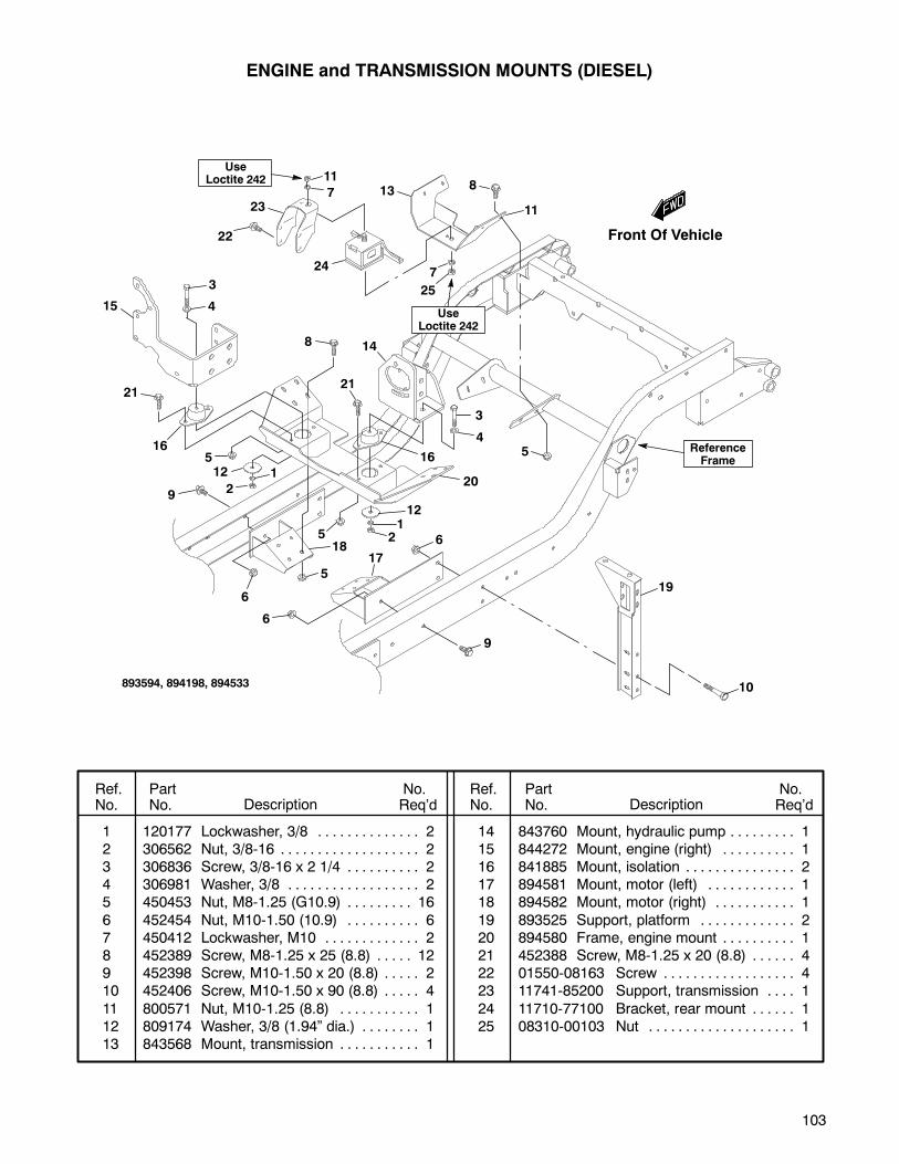
103
ReferenceFrame
893594, 894198, 894533
1 120177 Lockwasher, 3/8 2. . . . . . . . . . . . . .2 306562 Nut, 3/8-16 2. . . . . . . . . . . . . . . . . . .3 306836 Screw, 3/8-16 x 2 1/4 2. . . . . . . . . .4 306981 Washer, 3/8 2. . . . . . . . . . . . . . . . . .5 450453 Nut, M8-1.25 (G10.9) 16. . . . . . . . .
6 452454 Nut, M10-1.50 (10.9) 6. . . . . . . . . .7 450412 Lockwasher, M10 2. . . . . . . . . . . . .8 452389 Screw, M8-1.25 x 25 (8.8) 12. . . . .9 452398 Screw, M10-1.50 x 20 (8.8) 2. . . . .10 452406 Screw, M10-1.50 x 90 (8.8) 4. . . . .
11 800571 Nut, M10-1.25 (8.8) 1. . . . . . . . . . .12 809174 Washer, 3/8 (1.94” dia.) 1. . . . . . . .13 843568 Mount, transmission 1. . . . . . . . . . .
14 843760 Mount, hydraulic pump 1. . . . . . . . .15 844272 Mount, engine (right) 1. . . . . . . . . .16 841885 Mount, isolation 2. . . . . . . . . . . . . . .17 894581 Mount, motor (left) 1. . . . . . . . . . . .18 894582 Mount, motor (right) 1. . . . . . . . . . .
19 893525 Support, platform 2. . . . . . . . . . . . .20 894580 Frame, engine mount 1. . . . . . . . . .21 452388 Screw, M8-1.25 x 20 (8.8) 4. . . . . .22 01550-08163 Screw 4. . . . . . . . . . . . . . . . . .23 11741-85200 Support, transmission 1. . . .
24 11710-77100 Bracket, rear mount 1. . . . . .25 08310-00103 Nut 1. . . . . . . . . . . . . . . . . . . .
Ref.No.
PartNo. Description
No.Req’d
No.Req’dDescription
PartNo.
Ref.No.
ENGINE and TRANSMISSION MOUNTS (DIESEL)
7
8
10
13
24
25
19
7
11
11
UseLoctite 242
23
22
3
415
21
16
8
21
512 1
29
6
6
5
185
121
2
17
6
3
45
14
20
9
16
UseLoctite 242
Front Of Vehicle
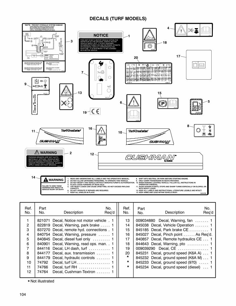
104
844177
844179
840845
840901
840748
WARNINGPARKING BRAKES ARE NOT AUTO-MATICALLY APPLIED. VEHICLE MAYMOVE CAUSING PERSONAL INJURYAND/OR PROPERTY DAMAGE. ALWAYSAPPLY HAND OR FOOT BRAKES.
822819
NOTICE
821071
THIS UNIT IS NOT A MOTOR VEHICLE WITHIN THEDEFINITION OF THE NATIONAL TRAFFIC MOTORVEHICLE SAFETY ACT. IT IS NOT DESIGNEDOR MANUFACTURED FOR USE ON ROADS, STREETSOR HIGHWAYS, NOR IS IT APPROPRIATE FORSUCH USE. IT IS NOR MEANT TO BE LICENSEDAS A MOTOR VEHICLE.
10
9
7
8
1 4
2
3
5
6
ACCESSORYCYLINDER
SELECTORVALVE
LIFTVALVE
MOTORDRIVEN
ACCESSORY
HYDRAULICTANK
HYDPUMP
PRESSURE
RETURN
SUCTION
PRESSUREOR RETURN
FOR MOTOR DRIVEN ACCESSORY AND
TRUCKSTER DUMP BOX OPERATION:PLUG 1--4, 2 --3, 8 --9, 7 --10.
FOR MOTOR DRIVEN ACCESSORY AND
INOPERABLE TRUCKSTER CYLINDER:PLUG 1--2, 3 --4, 8 --9, 7 --10.
FOR TRUCKSTER CYLINDER
OPERATION:PLUG 1--4, 2 --3, 7 --8.
FOR ACCESSORY CYLINDER
OPERATION:PLUG 1--5, 2 --6, 4 --3, 7 --8.
TRUCKSTERCYLINDER
FILTER
837270
HOSE REMOVED FROM ACCESSORY 8 MUSTBE CLEANED AND PLUGGED INTO RETURNPORT 7 TO PREVENT DAMAGE DUE TO ACC--IDENTAL ENGAGEMENT OF SELECTOR VALVE.
PREVENT HYDRAULIC SYSTEM DAMAGE
844116
DECALS (TURF MODELS)
Ref.No.
PartNo. Description
No.Req’d
No.Req’dDescription
PartNo.
Ref.No.
1 821071 Decal, Notice not motor vehicle 1.2 822819 Decal, Warning, park brake 1. . . . .3 837270 Decal, remote hyd. connections 1.4 840754 Decal, Warning, pressure 1. . . . . .5 840845 Decal, diesel fuel only 1. . . . . . . . .
6 840901 Decal, Warning, read ops. man. 1.7 844116 Decal, LH dash, turf 1. . . . . . . . . . .8 844177 Decal, aux. transmission 1. . . . . . .9 844179 Decal, hydraulic controls 1. . . . . . .10 74792 Decal, turf LH 1. . . . . . . . . . . . . . . . .
11 74766 Decal, turf RH 1. . . . . . . . . . . . . . . .12 74764 Decal, Cushman-Textron 1. . . . . . .
13 009034880 Decal, Warning, fan 1. . . . . . .14 845038 Decal, Vehicle Operation 1. . . . . . .15 845185 Decal, Park brake CE 1. . . . . . . . . .16 845027 Decal, Pinch point As Req’d.. . . . . .17 840857 Decal, Remote hydraulics CE 1. . .
18 844643 Decal, Warning, pto 1. . . . . . . . . . .19 009039290 Decal, CE 1. . . . . . . . . . . . . . . .20 845231 Decal, ground speed (K6A A) 1. . .
845232 Decal, ground speed (K6A M) 1. . .845233 Decal, ground speed (970) 1. . . . .
845234 Decal, ground speed (diesel) 1. . .
1
2
9
4
56
7
8
3
1011
12
13
845038
WARNING
FAILURE TO HEED THESEWARNINGS MAY RESULT INSERIOUS INJURY OR DEATH
1. READ AND UNDERSTAND ALL LABELS AND THE OPERATOR’S MANUAL.
2. DO NOT ALLOW UNTRAINED PERSONNEL TO OPERATE THIS VEHICLE.3. DO NOT MODIFY THIS VEHICLE WITHOUT MANUFACTURER’S AUTHORIZATION.4. PLACE LOADS FORWARD OF REAR AXLE.5. TOP HEAVY LOADS CAN CAUSE UPSETTING. DO NOT EXCEED PAYLOAD
CAPACITY.
6. DO NOT OPERATE IF REPAIRS ARE REQUIRED.7. KEEP ALL SHIELDS IN PLACE.
8. SHIFT INTO NEUTRAL OR PARK BEFORE STARTING ENGINE.
9. ONLY CARRY PASSENGERS IN SEATS PROVIDED.10. WHEN PARKING (LEAVING) VEHICLE, FOLLOW ALL INSTRUCTIONS IN
OPERATOR’S MANUAL.
11. AVOID SUDDEN STARTS, STOPS AND SHARP TURNS ESPECIALLY ON SLOPES, ORWITH HEAVY LOADS
12. KEEP ALL LABELS AND INSTRUCTIONAL LITERATURE LEGIBLE AND INTACT.13. KEEP ARMS AND LEGS WITHIN VEHICLE BODY.
14
845185
844643
*
19
15
16
17
18
20
* Not illustrated
74764G01
74792G0174792G01
*
*

105
1
2
3
4
5
6
7
8
9
10
11
11
10
7
7
6
5
9
8
CAMSHAFT and COMPONENTS (SUZUKI K6A)
7
Front Of Vehicle

106
1 4120030 Camshaft, intake 1. . . . . . . . . . . . . . . . . . . . . . . . . . . .2 4120031 Camshaft, exhaust 1. . . . . . . . . . . . . . . . . . . . . . . . . .3 4120032 Valve, intake 6. . . . . . . . . . . . . . . . . . . . . . . . . . . . . . . .4 4120033 Valve, exhaust 6. . . . . . . . . . . . . . . . . . . . . . . . . . . . . .5 4120034 Spring, valve 12. . . . . . . . . . . . . . . . . . . . . . . . . . . . . .6 4120035 Retainer, spring 12. . . . . . . . . . . . . . . . . . . . . . . . . . . .7 2701970 Cotter, valve 24. . . . . . . . . . . . . . . . . . . . . . . . . . . . . . .8 2701972 Seal, valve stem oil 12. . . . . . . . . . . . . . . . . . . . . . . . .9 2701971 Seat, spring 12. . . . . . . . . . . . . . . . . . . . . . . . . . . . . . .10 4119911 Tappet 12. . . . . . . . . . . . . . . . . . . . . . . . . . . . . . . . . . . .11 4119912 Shim, tappet As Req’d T:2.18. . . . . . . . . . . . . . . . . . . . . . . . .
4119913 Shim, tappet As Req’d T:2.20. . . . . . . . . . . . . . . . . . . . . . . . .4119914 Shim, tappet As Req’d T:2.22. . . . . . . . . . . . . . . . . . . . . . . . .4119915 Shim, tappet As Req’d T:2.24. . . . . . . . . . . . . . . . . . . . . . . . .4119916 Shim, tappet As Req’d T:2.26. . . . . . . . . . . . . . . . . . . . . . . . .4119917 Shim, tappet As Req’d T:2.28. . . . . . . . . . . . . . . . . . . . . . . . .4119918 Shim, tappet As Req’d T:2.30. . . . . . . . . . . . . . . . . . . . . . . . .4119919 Shim, tappet As Req’d T:2.32. . . . . . . . . . . . . . . . . . . . . . . . .4119920 Shim, tappet As Req’d T:2.34. . . . . . . . . . . . . . . . . . . . . . . . .4119921 Shim, tappet As Req’d T:2.36. . . . . . . . . . . . . . . . . . . . . . . . .4119922 Shim, tappet As Req’d T:2.38. . . . . . . . . . . . . . . . . . . . . . . . .4119923 Shim, tappet As Req’d T:2.40. . . . . . . . . . . . . . . . . . . . . . . . .4119924 Shim, tappet As Req’d T:2.42. . . . . . . . . . . . . . . . . . . . . . . . .4119925 Shim, tappet As Req’d T:2.44. . . . . . . . . . . . . . . . . . . . . . . . .4119926 Shim, tappet As Req’d T:2.46. . . . . . . . . . . . . . . . . . . . . . . . .4119927 Shim, tappet As Req’d T:2.48. . . . . . . . . . . . . . . . . . . . . . . . .4119928 Shim, tappet As Req’d T:2.50. . . . . . . . . . . . . . . . . . . . . . . . .4119929 Shim, tappet As Req’d T:2.52. . . . . . . . . . . . . . . . . . . . . . . . .4119930 Shim, tappet As Req’d T:2.46. . . . . . . . . . . . . . . . . . . . . . . . .4119931 Shim, tappet As Req’d T:2.46. . . . . . . . . . . . . . . . . . . . . . . . .4119932 Shim, tappet As Req’d T:2.46. . . . . . . . . . . . . . . . . . . . . . . . .4119933 Shim, tappet As Req’d T:2.46. . . . . . . . . . . . . . . . . . . . . . . . .4119934 Shim, tappet As Req’d T:2.46. . . . . . . . . . . . . . . . . . . . . . . . .4119935 Shim, tappet As Req’d T:2.46. . . . . . . . . . . . . . . . . . . . . . . . .4119936 Shim, tappet As Req’d T:2.46. . . . . . . . . . . . . . . . . . . . . . . . .4119937 Shim, tappet As Req’d T:2.46. . . . . . . . . . . . . . . . . . . . . . . . .4119938 Shim, tappet As Req’d T:2.46. . . . . . . . . . . . . . . . . . . . . . . . .4119939 Shim, tappet As Req’d T:2.46. . . . . . . . . . . . . . . . . . . . . . . . .4119940 Shim, tappet As Req’d T:2.46. . . . . . . . . . . . . . . . . . . . . . . . .4119941 Shim, tappet As Req’d T:2.46. . . . . . . . . . . . . . . . . . . . . . . . .4119942 Shim, tappet As Req’d T:2.46. . . . . . . . . . . . . . . . . . . . . . . . .4119943 Shim, tappet As Req’d T:2.46. . . . . . . . . . . . . . . . . . . . . . . . .4119944 Shim, tappet As Req’d T:2.46. . . . . . . . . . . . . . . . . . . . . . . . .4119945 Shim, tappet As Req’d T:2.46. . . . . . . . . . . . . . . . . . . . . . . . .4119946 Shim, tappet As Req’d T:2.46. . . . . . . . . . . . . . . . . . . . . . . . .4119947 Shim, tappet As Req’d T:2.46. . . . . . . . . . . . . . . . . . . . . . . . .4119948 Shim, tappet As Req’d T:2.46. . . . . . . . . . . . . . . . . . . . . . . . .4119949 Shim, tappet As Req’d T:2.46. . . . . . . . . . . . . . . . . . . . . . . . .4119950 Shim, tappet As Req’d T:2.46. . . . . . . . . . . . . . . . . . . . . . . . .4119951 Shim, tappet As Req’d T:2.46. . . . . . . . . . . . . . . . . . . . . . . . .4119952 Shim, tappet As Req’d T:2.46. . . . . . . . . . . . . . . . . . . . . . . . .4119953 Shim, tappet As Req’d T:2.46. . . . . . . . . . . . . . . . . . . . . . . . .
Ref.No.
PartNo.
Description NotesNo.Req’d
CAMSHAFT and COMPONENTS (SUZUKI K6A)
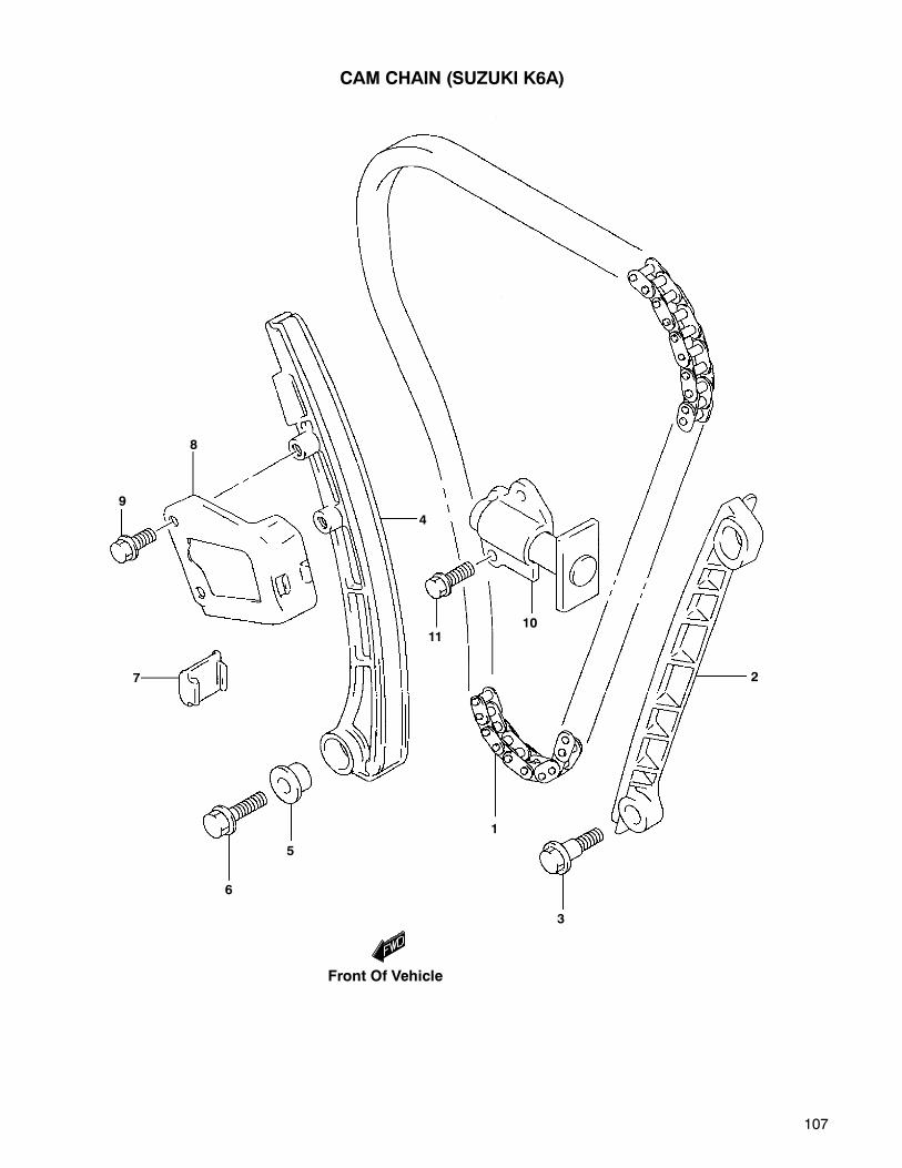
107
1
2
3
4
5
6
7
8
9
1011
CAM CHAIN (SUZUKI K6A)
Front Of Vehicle
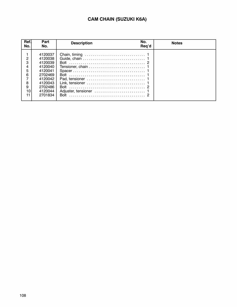
108
1 4120037 Chain, timing 1. . . . . . . . . . . . . . . . . . . . . . . . . . . . . . .2 4120038 Guide, chain 1. . . . . . . . . . . . . . . . . . . . . . . . . . . . . . . .3 4120039 Bolt 2. . . . . . . . . . . . . . . . . . . . . . . . . . . . . . . . . . . . . . .4 4120040 Tensioner, chain 1. . . . . . . . . . . . . . . . . . . . . . . . . . . . .5 4120041 Spacer 1. . . . . . . . . . . . . . . . . . . . . . . . . . . . . . . . . . . . .6 2702469 Bolt 1. . . . . . . . . . . . . . . . . . . . . . . . . . . . . . . . . . . . . . .7 4120042 Pad, tensioner 1. . . . . . . . . . . . . . . . . . . . . . . . . . . . . .8 4120043 Link, tensioner 1. . . . . . . . . . . . . . . . . . . . . . . . . . . . . .9 2702486 Bolt 2. . . . . . . . . . . . . . . . . . . . . . . . . . . . . . . . . . . . . . .10 4120044 Adjuster, tensioner 1. . . . . . . . . . . . . . . . . . . . . . . . . .11 2701834 Bolt 2. . . . . . . . . . . . . . . . . . . . . . . . . . . . . . . . . . . . . . .
Ref.No.
PartNo.
Description NotesNo.Req’d
CAM CHAIN (SUZUKI K6A)
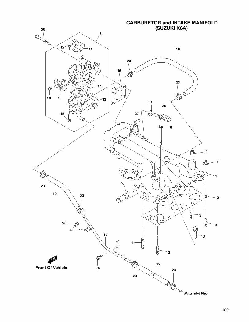
109
CARBURETOR and INTAKE MANIFOLD(SUZUKI K6A)
11
8
12
25
10 9
15
13
14
16
23
18
23
2021
27
6
7
7
1
2
3
3
3
3
4
23
22
23
24
17
26
2319
23
Water Inlet Pipe
Front Of Vehicle

110
1 4120045 Manifold, intake 1. . . . . . . . . . . . . . . . . . . . . . . . . . . . .2 4119959 Gasket 1. . . . . . . . . . . . . . . . . . . . . . . . . . . . . . . . . . . . .3 2702523 Stud bolt 3. . . . . . . . . . . . . . . . . . . . . . . . . . . . . . . . . . .4 4120047 Stud bolt 1. . . . . . . . . . . . . . . . . . . . . . . . . . . . . . . . . . .5 2701834 Bolt 6. . . . . . . . . . . . . . . . . . . . . . . . . . . . . . . . . . . . . . .6 4120048 Bolt 2. . . . . . . . . . . . . . . . . . . . . . . . . . . . . . . . . . . . . . .7 2701914 Nut 4. . . . . . . . . . . . . . . . . . . . . . . . . . . . . . . . . . . . . . . .8 4120049 Body, throttle 1. . . . . . . . . . . . . . . . . . . . . . . . . . . . . . .9 2701995 •Sensor, throttle position 1. . . . . . . . . . . . . . . . . . . . .10 2701996 •Screw 2. . . . . . . . . . . . . . . . . . . . . . . . . . . . . . . . . . . .11 2702477 •Sensor, pressure 1. . . . . . . . . . . . . . . . . . . . . . . . . . .12 2701998 •Screw 6. . . . . . . . . . . . . . . . . . . . . . . . . . . . . . . . . . . .13 2701999 •Valve, ISC 1. . . . . . . . . . . . . . . . . . . . . . . . . . . . . . . . .14 2702000 •Gasket 1. . . . . . . . . . . . . . . . . . . . . . . . . . . . . . . . . . . .15 2701998 •Screw 4. . . . . . . . . . . . . . . . . . . . . . . . . . . . . . . . . . . .16 2701803 Gasket 1. . . . . . . . . . . . . . . . . . . . . . . . . . . . . . . . . . . . .17 4120025 Hose, water 1. . . . . . . . . . . . . . . . . . . . . . . . . . . . . . . .18 4120050 Hose, water throttle inlet 1. . . . . . . . . . . . . . . . . . . . .19 4116846 Hose, water 1. . . . . . . . . . . . . . . . . . . . . . . . . . . . . . . .20 4120051 Sensor, inlet air temperature 1. . . . . . . . . . . . . . . . . .21 4120052 Gasket 1. . . . . . . . . . . . . . . . . . . . . . . . . . . . . . . . . . . . .22 4120100 Hose, water 1. . . . . . . . . . . . . . . . . . . . . . . . . . . . . . . .23 2702429 Clip 2. . . . . . . . . . . . . . . . . . . . . . . . . . . . . . . . . . . . . . .24 2702486 Bolt 1. . . . . . . . . . . . . . . . . . . . . . . . . . . . . . . . . . . . . . .25 2702001 Bolt, throttle body 4. . . . . . . . . . . . . . . . . . . . . . . . . . .26 2702475 Bolt 1. . . . . . . . . . . . . . . . . . . . . . . . . . . . . . . . . . . . . . .27 2702431 Plug 1. . . . . . . . . . . . . . . . . . . . . . . . . . . . . . . . . . . . . . .
Ref.No.
PartNo.
Description NotesNo.Req’d
•INDENTED PART NAMES INDICATE THESE PARTS ARE INCLUDED IN PRECEDING ASSEMBLY.
CARBURETOR and INTAKE MANIFOLD(SUZUKI K6A)

111
1 4120054 Hose, breather 1. . . . . . . . . . . . . . . . . . . . . . . . . . . . . .2 2702484 Clip 2. . . . . . . . . . . . . . . . . . . . . . . . . . . . . . . . . . . . . . .3 2702485 Clamp 1. . . . . . . . . . . . . . . . . . . . . . . . . . . . . . . . . . . . .4 2702486 Bolt 1. . . . . . . . . . . . . . . . . . . . . . . . . . . . . . . . . . . . . . .5 4120055 Hose, PCV 1. . . . . . . . . . . . . . . . . . . . . . . . . . . . . . . . .6 2702489 Seal, PCV valve 1. . . . . . . . . . . . . . . . . . . . . . . . . . . .7 4120056 Valve, PCV 1. . . . . . . . . . . . . . . . . . . . . . . . . . . . . . . . .8 2702491 Clip 2. . . . . . . . . . . . . . . . . . . . . . . . . . . . . . . . . . . . . . .9 4120057 Clamp 1. . . . . . . . . . . . . . . . . . . . . . . . . . . . . . . . . . . . .10 2702486 Bolt 1. . . . . . . . . . . . . . . . . . . . . . . . . . . . . . . . . . . . . . .
Ref.No.
PartNo.
Description NotesNo.Req’d
BREATHER HOSE (SUZUKI K6A)
2
1
43
2
67
8
5
9
10
8
Intake Manifold
Front Of Vehicle
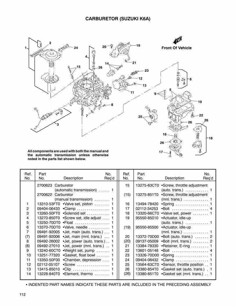
112
2700623 Carburetor(automatic transmission) 1. . . . . .
2700622 Carburetor(manual transmission) 1. . . . . . . .
1 13310-53FT0 Valve set, piston 1. . . . . . . .
2 09404-06433 Clamp 1. . . . . . . . . . . . . . . . .3 13260-50FT0 Solenoid set 1. . . . . . . . . . . .4 13270-850T0 Screw set, idle adjust 1. . . .5 13250-70DT0 Float 1. . . . . . . . . . . . . . . . . .6 13370-70DT0 Valve, needle 1. . . . . . . . . . .
7 09491-92005 Jet, main (auto. trans.) 1. . .09491-92006 Jet, main (mnl. trans.) 1. . .
8 09492-26002 Jet, power (auto. trans.) 1. .09492-27010 Jet, power (mnl. trans.) 1. .
9 13240-60CT0 Weight set, pump 1. . . . . . .10 13251-77320 Gasket, float bowl 1. . . . . . .
11 13350-50F00 Chamber, depression 1. . . .12 02112-05107 Screw 1. . . . . . . . . . . . . . . . .13 13415-85010 Clip 1. . . . . . . . . . . . . . . . . . .14 13228-840T0 Element, thermo 1. . . . . . . .
15 13275-63CT0 Screw, throttle adjustment(auto. trans.) 1. . . . . . . . . . . .
13275-851T0 Screw, throttle adjustment(mnl. trans.) 1. . . . . . . . . . . . .
16 13494-78420 Spring 1. . . . . . . . . . . . . . . . .
17 02112-34253 Bolt 4. . . . . . . . . . . . . . . . . . .18 13320-66CT0 Valve set, power 1. . . . . . . .19 95550-85010 Actuator, idle-up
(auto. trans.) 1. . . . . . . . . . . .95550-85500 Actuator, idle-up
(mnl. trans.) 1. . . . . . . . . . . . .20 13372-70D00 Bolt (auto. trans.) 2. . . . . . .
09137-05009 Bolt (mnl. trans.) 2. . . . . . . .21 13384-78330 Retainer, E-ring 1. . . . . . . . .22 13601-05148 Bolt 4. . . . . . . . . . . . . . . . . . .23 13326-70D00 Spring 1. . . . . . . . . . . . . . . . .
24 09404-06432 Clamp 1. . . . . . . . . . . . . . . . .25 13564-63CT0 Sensor, throttle position 1. .26 13380-854T0 Gasket set (auto. trans.) 1.
13380-851T0 Gasket set (mnl. trans.) 1. .
Ref.No.
PartNo. Description
No.Req’d
No.Req’dDescription
PartNo.
Ref.No.
CARBURETOR (SUZUKI K6A)
1
2
24
15
3
26
4
20 19
2114
23
12
13
11
8
7
6
25
17
16
26
18
22
10
59
26
26
INDENTED PART NAMES INDICATE THESE PARTS ARE INCLUDED IN THE PRECEDING ASSEMBLY
All components are usedwith both themanual andthe automatic transmission unless otherwisenoted in the parts list shown below.
(7)
(8)
(15)
(19)
(20)
(26)
Front Of Vehicle
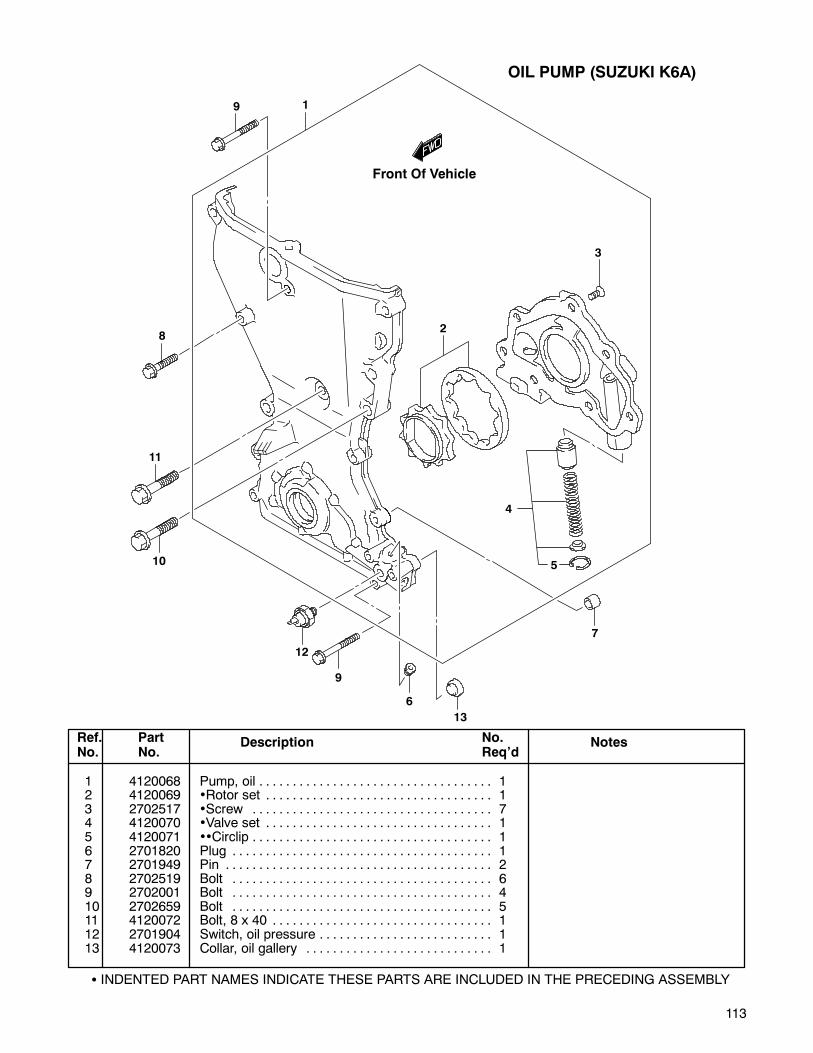
113
1 4120068 Pump, oil 1. . . . . . . . . . . . . . . . . . . . . . . . . . . . . . . . . . .2 4120069 •Rotor set 1. . . . . . . . . . . . . . . . . . . . . . . . . . . . . . . . . .3 2702517 •Screw 7. . . . . . . . . . . . . . . . . . . . . . . . . . . . . . . . . . . .4 4120070 •Valve set 1. . . . . . . . . . . . . . . . . . . . . . . . . . . . . . . . . .5 4120071 ••Circlip 1. . . . . . . . . . . . . . . . . . . . . . . . . . . . . . . . . . . .6 2701820 Plug 1. . . . . . . . . . . . . . . . . . . . . . . . . . . . . . . . . . . . . . .7 2701949 Pin 2. . . . . . . . . . . . . . . . . . . . . . . . . . . . . . . . . . . . . . . .8 2702519 Bolt 6. . . . . . . . . . . . . . . . . . . . . . . . . . . . . . . . . . . . . . .9 2702001 Bolt 4. . . . . . . . . . . . . . . . . . . . . . . . . . . . . . . . . . . . . . .10 2702659 Bolt 5. . . . . . . . . . . . . . . . . . . . . . . . . . . . . . . . . . . . . . .11 4120072 Bolt, 8 x 40 1. . . . . . . . . . . . . . . . . . . . . . . . . . . . . . . . .12 2701904 Switch, oil pressure 1. . . . . . . . . . . . . . . . . . . . . . . . . .13 4120073 Collar, oil gallery 1. . . . . . . . . . . . . . . . . . . . . . . . . . . .
Ref.No.
PartNo.
Description NotesNo.Req’d
OIL PUMP (SUZUKI K6A)
INDENTED PART NAMES INDICATE THESE PARTS ARE INCLUDED IN THE PRECEDING ASSEMBLY
8
1
2
3
4
5
6
7
9
10
11
12
9
13
Front Of Vehicle

114
GEAR SHIFT FORK (MANUAL TRANSMISSION) (SUZUKI K6A)
35
3719 13
12
35
17
18363114
21
20
3229
3330
34
27
22
25
38
39
18
15
4910
111
8
5
10
119
2
11
10
6
9
3
7
26
24
15
16
23
Front Of Vehicle
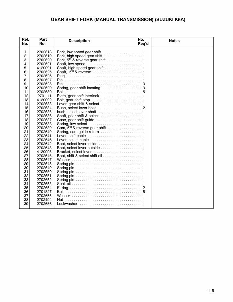
115
1 2702618 Fork, low speed gear shift 1. . . . . . . . . . . . . . . . . . . .2 2702619 Fork, high speed gear shift 1. . . . . . . . . . . . . . . . . . .3 2702620 Fork, 5th & reverse gear shift 1. . . . . . . . . . . . . . . . . .4 2702621 Shaft, low speed 1. . . . . . . . . . . . . . . . . . . . . . . . . . . .5 4120091 Shaft, high speed gear shift 1. . . . . . . . . . . . . . . . . . .6 2702625 Shaft, 5th & reverse 1. . . . . . . . . . . . . . . . . . . . . . . . .7 2702626 Plug 1. . . . . . . . . . . . . . . . . . . . . . . . . . . . . . . . . . . . . . .8 2702627 Pin 1. . . . . . . . . . . . . . . . . . . . . . . . . . . . . . . . . . . . . . . .9 2702628 Pin 3. . . . . . . . . . . . . . . . . . . . . . . . . . . . . . . . . . . . . . . .10 2702629 Spring, gear shift locating 3. . . . . . . . . . . . . . . . . . . .11 2702630 Ball 5. . . . . . . . . . . . . . . . . . . . . . . . . . . . . . . . . . . . . . . .12 2701111 Plate, gear shift interlock 1. . . . . . . . . . . . . . . . . . . . .13 4120092 Bolt, gear shift stop 1. . . . . . . . . . . . . . . . . . . . . . . . . .14 2702633 Lever, gear shift & select 1. . . . . . . . . . . . . . . . . . . . .15 2702634 Bush, select lever boss 2. . . . . . . . . . . . . . . . . . . . . .16 2702635 bush, select lever shaft 1. . . . . . . . . . . . . . . . . . . . . .17 2702636 Shaft, gear shift & select 1. . . . . . . . . . . . . . . . . . . . .18 2702637 Case, gear shift guide 1. . . . . . . . . . . . . . . . . . . . . . . .19 2702638 Spring, low select 1. . . . . . . . . . . . . . . . . . . . . . . . . . .20 2702639 Cam, 5th & reverse gear shift 1. . . . . . . . . . . . . . . . .21 2702640 Spring, cam guide return 1. . . . . . . . . . . . . . . . . . . . .22 2702641 Lever, shift cable 1. . . . . . . . . . . . . . . . . . . . . . . . . . . .23 2702646 Lever, select cable 1. . . . . . . . . . . . . . . . . . . . . . . . . .24 2702642 Boot, select lever inside 1. . . . . . . . . . . . . . . . . . . . . .25 2702643 Boot, select lever outside 1. . . . . . . . . . . . . . . . . . . . .26 4120093 Bracket, select lever 1. . . . . . . . . . . . . . . . . . . . . . . . .27 2702645 Boot, shift & select shift oil 1. . . . . . . . . . . . . . . . . . . .28 2702647 Washer 1. . . . . . . . . . . . . . . . . . . . . . . . . . . . . . . . . . . .29 2702648 Spring pin 1. . . . . . . . . . . . . . . . . . . . . . . . . . . . . . . . . .30 2702649 Spring pin 1. . . . . . . . . . . . . . . . . . . . . . . . . . . . . . . . . .31 2702650 Spring pin 1. . . . . . . . . . . . . . . . . . . . . . . . . . . . . . . . . .32 2702651 Spring pin 1. . . . . . . . . . . . . . . . . . . . . . . . . . . . . . . . . .33 2702652 Spring pin 1. . . . . . . . . . . . . . . . . . . . . . . . . . . . . . . . . .34 2702653 Seal, oil 1. . . . . . . . . . . . . . . . . . . . . . . . . . . . . . . . . . . .35 2702654 E--ring 2. . . . . . . . . . . . . . . . . . . . . . . . . . . . . . . . . . . . .36 2701827 Bolt 5. . . . . . . . . . . . . . . . . . . . . . . . . . . . . . . . . . . . . . .37 2702655 Washer 1. . . . . . . . . . . . . . . . . . . . . . . . . . . . . . . . . . . .38 2702494 Nut 1. . . . . . . . . . . . . . . . . . . . . . . . . . . . . . . . . . . . . . . .39 2702656 Lockwasher 1. . . . . . . . . . . . . . . . . . . . . . . . . . . . . . . .
Ref.No.
PartNo.
Description NotesNo.Req’d
GEAR SHIFT FORK (MANUAL TRANSMISSION) (SUZUKI K6A)
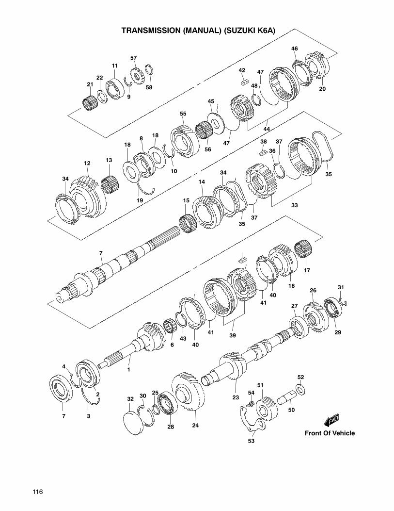
116
TRANSMISSION (MANUAL) (SUZUKI K6A)
2122
11
9
57
58
34
1213
188
18
10
55
56
45
47
48
42 47
46
20
44
38 37
36
35
33
3735
34
14
15
7
7
4
2
3
1
643
40
4139
41
40
16
17
31
29
26
27
23
24
25
28
3032
53
54
51
50
52
19
Front Of Vehicle
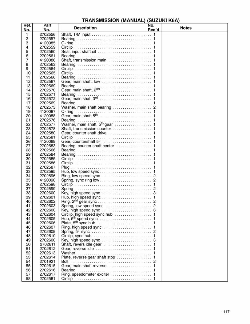
117
1 2702556 Shaft, T/M input 1. . . . . . . . . . . . . . . . . . . . . . . . . . . . .2 2702557 Bearing 1. . . . . . . . . . . . . . . . . . . . . . . . . . . . . . . . . . . .3 4120085 C--ring 1. . . . . . . . . . . . . . . . . . . . . . . . . . . . . . . . . . . . .4 2702559 Circlip 1. . . . . . . . . . . . . . . . . . . . . . . . . . . . . . . . . . . . .5 2702560 Seal, input shaft oil 1. . . . . . . . . . . . . . . . . . . . . . . . . .6 2702561 Bearing 1. . . . . . . . . . . . . . . . . . . . . . . . . . . . . . . . . . . .7 4120086 Shaft, transmission main 1. . . . . . . . . . . . . . . . . . . . .8 2702563 Bearing 1. . . . . . . . . . . . . . . . . . . . . . . . . . . . . . . . . . . .9 2702564 Circlip 1. . . . . . . . . . . . . . . . . . . . . . . . . . . . . . . . . . . . .10 2702565 Circlip 1. . . . . . . . . . . . . . . . . . . . . . . . . . . . . . . . . . . . .11 2702566 Bearing 1. . . . . . . . . . . . . . . . . . . . . . . . . . . . . . . . . . . .12 2702567 Gear, main shaft, low 1. . . . . . . . . . . . . . . . . . . . . . . .13 2702569 Bearing 1. . . . . . . . . . . . . . . . . . . . . . . . . . . . . . . . . . . .14 2702570 Gear, main shaft, 2nd 1. . . . . . . . . . . . . . . . . . . . . . . .15 2702571 Bearing 1. . . . . . . . . . . . . . . . . . . . . . . . . . . . . . . . . . . .16 2702572 Gear, main shaft 3rd 1. . . . . . . . . . . . . . . . . . . . . . . . .17 2702569 Bearing 1. . . . . . . . . . . . . . . . . . . . . . . . . . . . . . . . . . . .18 2702573 Washer, main shaft bearing 2. . . . . . . . . . . . . . . . . . .19 4120087 C--ring 1. . . . . . . . . . . . . . . . . . . . . . . . . . . . . . . . . . . . .20 4120088 Gear, main shaft 5th 1. . . . . . . . . . . . . . . . . . . . . . . . .21 2702576 Bearing 1. . . . . . . . . . . . . . . . . . . . . . . . . . . . . . . . . . . .22 2702577 Washer, main shaft, 5th gear 1. . . . . . . . . . . . . . . . . .23 2702578 Shaft, transmission counter 1. . . . . . . . . . . . . . . . . . .24 2702580 Gear, counter shaft drive 1. . . . . . . . . . . . . . . . . . . . .25 2702581 Circlip 1. . . . . . . . . . . . . . . . . . . . . . . . . . . . . . . . . . . . .26 4120089 Gear, countershaft 5th 1. . . . . . . . . . . . . . . . . . . . . . .27 2702583 Bearing, counter shaft center 1. . . . . . . . . . . . . . . . .28 2702566 Bearing 1. . . . . . . . . . . . . . . . . . . . . . . . . . . . . . . . . . . .29 2702584 Bearing 1. . . . . . . . . . . . . . . . . . . . . . . . . . . . . . . . . . . .30 2702585 Circlip 1. . . . . . . . . . . . . . . . . . . . . . . . . . . . . . . . . . . . .31 2702586 Circlip 1. . . . . . . . . . . . . . . . . . . . . . . . . . . . . . . . . . . . .32 2702587 Plug 1. . . . . . . . . . . . . . . . . . . . . . . . . . . . . . . . . . . . . . .33 2702595 Hub, low speed sync 1. . . . . . . . . . . . . . . . . . . . . . . . .34 2702596 Ring, low speed sync 2. . . . . . . . . . . . . . . . . . . . . . . .35 4120090 Spring, sync ring low 2. . . . . . . . . . . . . . . . . . . . . . . . .36 2702598 Circlip 1. . . . . . . . . . . . . . . . . . . . . . . . . . . . . . . . . . . . .37 2702599 Spring 2. . . . . . . . . . . . . . . . . . . . . . . . . . . . . . . . . . . . .38 2702600 Key, high speed sync 3. . . . . . . . . . . . . . . . . . . . . . . .39 2702601 Hub, high speed sync 1. . . . . . . . . . . . . . . . . . . . . . . .40 2702602 Ring, 2nd gear sync 2. . . . . . . . . . . . . . . . . . . . . . . . . .41 2702603 Spring, low speed sync 2. . . . . . . . . . . . . . . . . . . . . .42 2702600 Key, high speed sync 3. . . . . . . . . . . . . . . . . . . . . . . .43 2702604 Circlip, high speed sync hub 1. . . . . . . . . . . . . . . . . .44 2702605 Hub, 5th speed sync 1. . . . . . . . . . . . . . . . . . . . . . . . .45 2702606 Plate, 5th sync hub 1. . . . . . . . . . . . . . . . . . . . . . . . . .46 2702607 Ring, high speed sync 1. . . . . . . . . . . . . . . . . . . . . . .47 2702609 Spring, 5th sync 2. . . . . . . . . . . . . . . . . . . . . . . . . . . . .48 2702610 Circlip, sync hub 1. . . . . . . . . . . . . . . . . . . . . . . . . . . .49 2702600 Key, high speed sync 3. . . . . . . . . . . . . . . . . . . . . . . .50 2702611 Shaft, revers idle gear 1. . . . . . . . . . . . . . . . . . . . . . .51 2702612 Gear, reverse idle 1. . . . . . . . . . . . . . . . . . . . . . . . . . .52 2702613 Washer 1. . . . . . . . . . . . . . . . . . . . . . . . . . . . . . . . . . . .53 2702614 Plate, reverse gear shaft stop 1. . . . . . . . . . . . . . . . .54 2701921 Bolt 2. . . . . . . . . . . . . . . . . . . . . . . . . . . . . . . . . . . . . . .55 2702615 Gear, main shaft reverse 1. . . . . . . . . . . . . . . . . . . . .56 2702616 Bearing 1. . . . . . . . . . . . . . . . . . . . . . . . . . . . . . . . . . . .57 2702617 Ring, speedometer exciter 1. . . . . . . . . . . . . . . . . . . .58 2702581 Circlip 1. . . . . . . . . . . . . . . . . . . . . . . . . . . . . . . . . . . . .
Ref.No.
PartNo. Description Notes
No.Req’d
TRANSMISSION (MANUAL) (SUZUKI K6A)
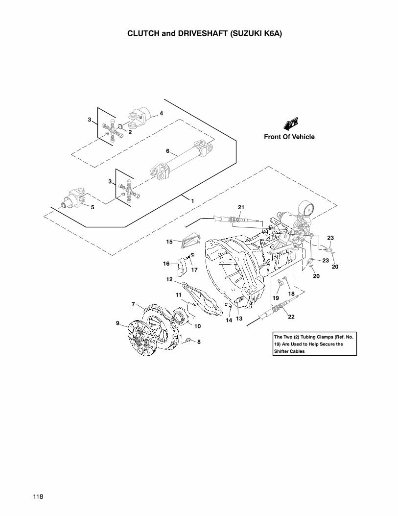
118
CLUTCH and DRIVESHAFT (SUZUKI K6A)
The Two (2) Tubing Clamps (Ref. No.
19) Are Used to Help Secure the
Shifter Cables
4
2
3
6
3
51
21
15
1617
12
11
7
9
8
1014 13 22
1918
20
2320
23
Front Of Vehicle

119
1 2701321.7 Driveshaft, complete 1. . . . . . . . . . . . . . . . . . . . . . . . .2 548482 • Plug, expansion 3. . . . . . . . . . . . . . . . . . . . . . . . . . .3 826284 • Cross, u--joint 2. . . . . . . . . . . . . . . . . . . . . . . . . . . . .4 826285 • Yoke, universal 1. . . . . . . . . . . . . . . . . . . . . . . . . . .5 894192 • Yoke, front 1. . . . . . . . . . . . . . . . . . . . . . . . . . . . . . .6 895126 • Shaft, drive 1. . . . . . . . . . . . . . . . . . . . . . . . . . . . . . .7 4117900 Cover, clutch 1. . . . . . . . . . . . . . . . . . . . . . . . . . . . . . .8 2702547 Bolt, 8 x 16 6. . . . . . . . . . . . . . . . . . . . . . . . . . . . . . . . .9 2702548 Disc, clutch 1. . . . . . . . . . . . . . . . . . . . . . . . . . . . . . . . .10 2702549 Bearing, clutch release 1. . . . . . . . . . . . . . . . . . . . . . .11 2702550 Clip, clutch release bearing 1. . . . . . . . . . . . . . . . . . .12 2702551 Fork, clutch release 1. . . . . . . . . . . . . . . . . . . . . . . . .13 2702552 Support, clutch release fork 1. . . . . . . . . . . . . . . . . . .14 2702553 Clip, clutch release fork 1. . . . . . . . . . . . . . . . . . . . . .15 2702554 Cap, transmission case 1. . . . . . . . . . . . . . . . . . . . . .16 2702555 Bracket, clutch cable 1. . . . . . . . . . . . . . . . . . . . . . . .17 2702470 Bolt 1. . . . . . . . . . . . . . . . . . . . . . . . . . . . . . . . . . . . . . .18 800843 Screw, #10--14 taptite (plastic) 2. . . . . . . . . . . . . . . .19 809092 Clamp, tube/wire 2. . . . . . . . . . . . . . . . . . . . . . . . . . . .20 821164 Pin, hair .25 x 1.12 x .06 2. . . . . . . . . . . . . . . . . . . . .21 2701273 Cable, shifter 97” (2464 mm) 1. . . . . . . . . . . . . . . . . .22 2701273 Cable, shifter 97” (2464 mm) 1. . . . . . . . . . . . . . . . . .23 2701371 Connector, shifter lever 2. . . . . . . . . . . . . . . . . . . . . .
Ref.No.
PartNo.
Description NotesNo.Req’d
CLUTCH and DRIVESHAFT (SUZUKI K6A)
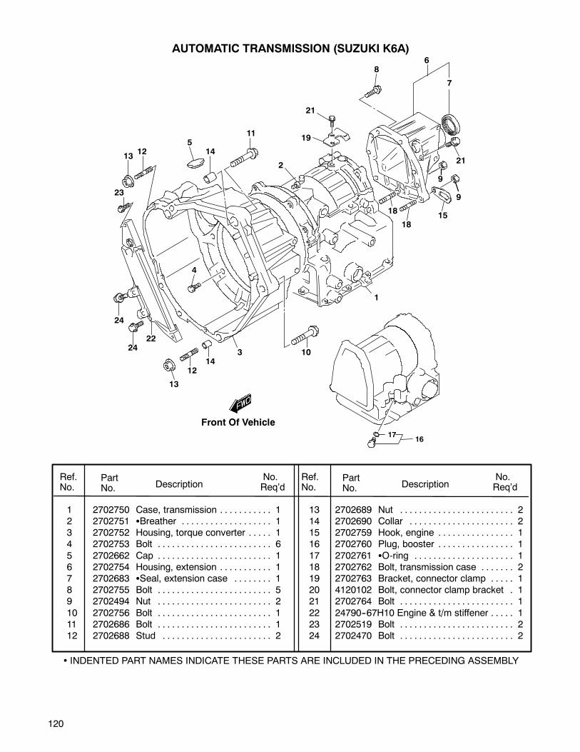
120
AUTOMATIC TRANSMISSION (SUZUKI K6A)
1 2702750 Case, transmission 1. . . . . . . . . . .2 2702751 Breather 1. . . . . . . . . . . . . . . . . . .3 2702752 Housing, torque converter 1. . . . .4 2702753 Bolt 6. . . . . . . . . . . . . . . . . . . . . . . .
5 2702662 Cap 1. . . . . . . . . . . . . . . . . . . . . . . .6 2702754 Housing, extension 1. . . . . . . . . . .7 2702683 Seal, extension case 1. . . . . . . .8 2702755 Bolt 5. . . . . . . . . . . . . . . . . . . . . . . .9 2702494 Nut 2. . . . . . . . . . . . . . . . . . . . . . . .
10 2702756 Bolt 1. . . . . . . . . . . . . . . . . . . . . . . .11 2702686 Bolt 1. . . . . . . . . . . . . . . . . . . . . . . .12 2702688 Stud 2. . . . . . . . . . . . . . . . . . . . . . .
13 2702689 Nut 2. . . . . . . . . . . . . . . . . . . . . . . .14 2702690 Collar 2. . . . . . . . . . . . . . . . . . . . . .15 2702759 Hook, engine 1. . . . . . . . . . . . . . . .16 2702760 Plug, booster 1. . . . . . . . . . . . . . . .
17 2702761 O-ring 1. . . . . . . . . . . . . . . . . . . . .18 2702762 Bolt, transmission case 2. . . . . . .19 2702763 Bracket, connector clamp 1. . . . .20 4120102 Bolt, connector clamp bracket 1.21 2702764 Bolt 1. . . . . . . . . . . . . . . . . . . . . . . .
22 24790--67H10 Engine & t/m stiffener 1. . . . .23 2702519 Bolt 2. . . . . . . . . . . . . . . . . . . . . . . .24 2702470 Bolt 2. . . . . . . . . . . . . . . . . . . . . . . .
Ref.No.
PartNo. Description
No.Req’d
No.Req’dDescription
PartNo.
Ref.No.
• INDENTED PART NAMES INDICATE THESE PARTS ARE INCLUDED IN THE PRECEDING ASSEMBLY
Front Of Vehicle
21
19
2
86
7
21
9
9
1518
18
1
10314
12
13
2422
24
4
23
1312
514
11
1716
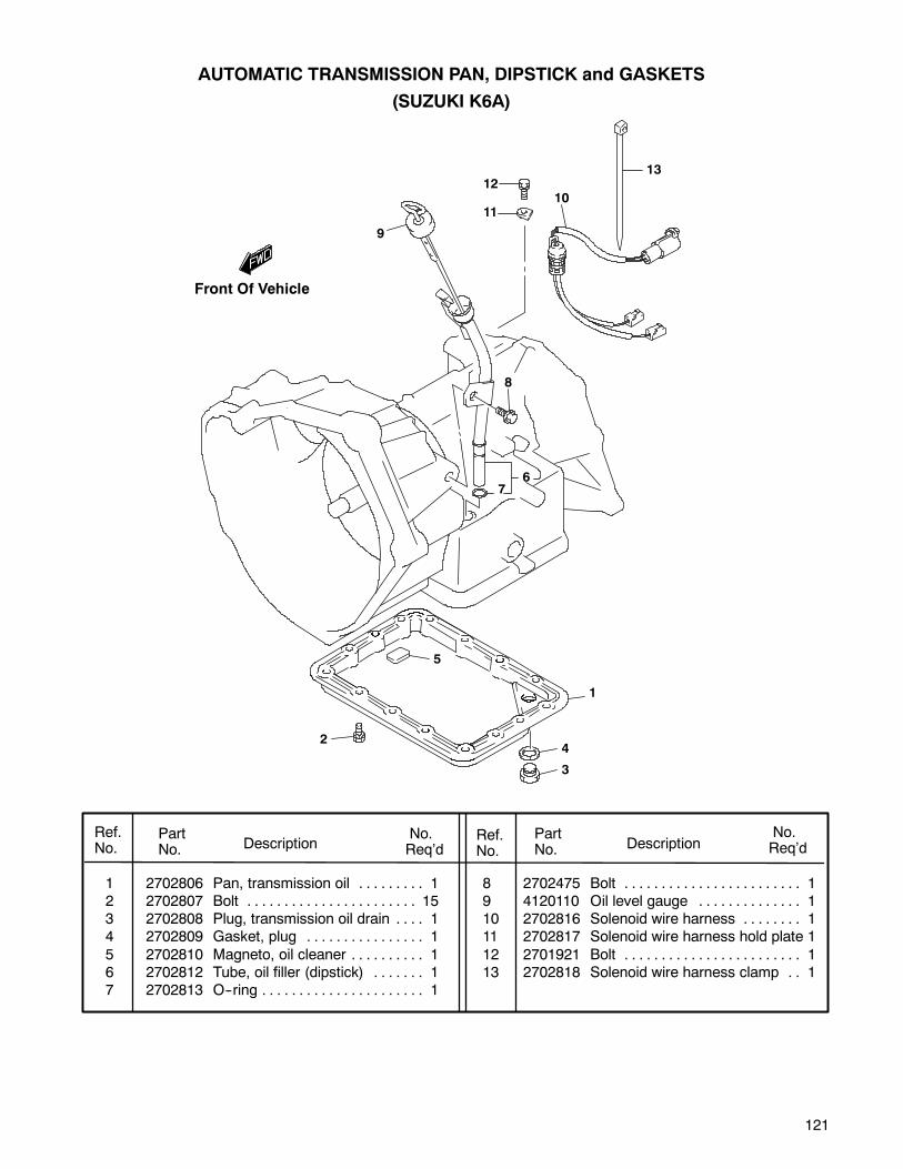
121
AUTOMATIC TRANSMISSION PAN, DIPSTICK and GASKETS
(SUZUKI K6A)
1 2702806 Pan, transmission oil 1. . . . . . . . .2 2702807 Bolt 15. . . . . . . . . . . . . . . . . . . . . . .3 2702808 Plug, transmission oil drain 1. . . .4 2702809 Gasket, plug 1. . . . . . . . . . . . . . . .
5 2702810 Magneto, oil cleaner 1. . . . . . . . . .6 2702812 Tube, oil filler (dipstick) 1. . . . . . .7 2702813 O--ring 1. . . . . . . . . . . . . . . . . . . . . .
8 2702475 Bolt 1. . . . . . . . . . . . . . . . . . . . . . . .9 4120110 Oil level gauge 1. . . . . . . . . . . . . .10 2702816 Solenoid wire harness 1. . . . . . . .11 2702817 Solenoid wire harness hold plate 1
12 2701921 Bolt 1. . . . . . . . . . . . . . . . . . . . . . . .13 2702818 Solenoid wire harness clamp 1. .
Ref.No.
PartNo. Description
No.Req’d
No.Req’dDescription
PartNo.
Ref.No.
1213
1011
9
8
76
5
1
4
3
2
Front Of Vehicle

122
TRANSMISSION TUBES, OIL PUMP, SOLENOIDS and SHIFT SWITCH
(AUTOMATIC TRANSMISSION) (SUZUKI K6A)
Ref.No.
PartNo. Description
No.Req’d
No.Req’dDescription
PartNo.
Ref.No.
• INDENTED PART NAMES INDICATE THESE PARTS ARE INCLUDED IN THE PRECEDING ASSEMBLY
7
6
5
8
1 2702843 Pipe assembly, oil 1. . . . . . . . . . . .2 2702849 Bolt 1. . . . . . . . . . . . . . . . . . . . . . . .3 2702847 Union bolt 2. . . . . . . . . . . . . . . . . . .4 2702845 Gasket 4. . . . . . . . . . . . . . . . . . . . .
5 2702765 Pump, oil 1. . . . . . . . . . . . . . . . . . .6 2702766 Seal, oil pump 1. . . . . . . . . . . . . .7 2702767 Bolt, oil pump 8. . . . . . . . . . . . . . . .8 2702768 Ring set, oil pump seal 1. . . . . . .9 2702822 Solenoid, direct clutch 1. . . . . . . .
10 2702823 O-ring 1. . . . . . . . . . . . . . . . . . . . .11 2702824 Solenoid, 2nd brake 1. . . . . . . . . .
12 2702823 O-ring 1. . . . . . . . . . . . . . . . . . . . .13 2702764 Bolt 2. . . . . . . . . . . . . . . . . . . . . . . .14 2702885 Switch, shift 1. . . . . . . . . . . . . . . . .15 2702886 Bolt 1. . . . . . . . . . . . . . . . . . . . . . . .
16 2702881 Joint, transmission shifter 2. . . . .17 2702882 Bushing 1. . . . . . . . . . . . . . . . . . . .18 2702883 Washer 1. . . . . . . . . . . . . . . . . . . . .19 2702884 E-ring 1. . . . . . . . . . . . . . . . . . . . . .20 842740 Lever, shifter 1. . . . . . . . . . . . . . . . .
21 825624 Clamp, hose 2. . . . . . . . . . . . . . . . . .22 826590 Hose, 5/16 i.d. As Req’d.. . . . . . . . .
9
14 15
10
11
12
13
13
2
1
3
4
4
21
22
ToOil Cooler
20
16
17
18
19
Front Of Vehicle

123
1 12710-77314 Camshaft 1. . . . . . . . . . . . . . .2 09283-32040 Seal, camshaft 1. . . . . . . . . .3 12749-73002 Plate, cam shaft thrust 1. . . .4 02122-06123 Screw 2. . . . . . . . . . . . . . . . . .5 12860-73004 Shaft, valve rocker 2. . . . . . .
6 02122-06163 Screw 10. . . . . . . . . . . . . . . . .7 12841-77300 Arm, valve rocker 8. . . . . . . .8 12891-51G00 Spring, rocker arm 8. . . . . . .9 12848-73010 Screw, valve adjusting 8. . . .
10 09159-07002 Nut 8. . . . . . . . . . . . . . . . . . . .11 12911-78101 Valve, inlet 4. . . . . . . . . . . . . .12 12915-84010 Valve, exhaust 4. . . . . . . . . . .13 12921-73002 Spring, valve 8. . . . . . . . . . . .14 12900-82810 Retainer, valve spring 8. . . .
15 12932-82000 Cotter, valve 16. . . . . . . . . . .16 12933-73000 Seat, valve spring 8. . . . . . . .17 09289-07007 Seal, oil 8. . . . . . . . . . . . . . . .
Ref.No.
PartNo. Description
No.Req’d
No.Req’dDescription
PartNo.
Ref.No.
CAMSHAFT & COMPONENTS
(SUZUKI 970)
4
5
11
10
8
5
3
16
1514
17
12
13
17
9
10
7
16
6
2
1
13
1514
7
8
9
6
INDENTED PART NAMES INDICATE THESE PARTS ARE INCLUDED IN THE PRECEDING ASSEMBLY
Front Of Vehicle
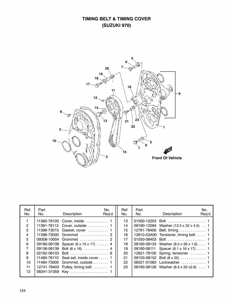
124
1 11360-78100 Cover, inside 1. . . . . . . . . . . .2 11391-78113 Cover, outside 1. . . . . . . . . . .3 11399-73010 Gasket, cover 1. . . . . . . . . . .4 11398-73000 Grommet 2. . . . . . . . . . . . . . .5 09308-10004 Grommet 2. . . . . . . . . . . . . . .
6 09180-06106 Spacer (6 x 10 x 17) 4. . . . . .7 09136-06139 Bolt (6 x 16) 4. . . . . . . . . . . . .8 02162-06103 Bolt 6. . . . . . . . . . . . . . . . . . . .9 11480-78110 Seal set, inside cover 1. . . . .10 11484-73000 Grommet, outside 1. . . . . . . .
11 12741-78403 Pulley, timing belt 1. . . . . . . .12 08341-31059 Key 1. . . . . . . . . . . . . . . . . . . .
13 01500-12253 Bolt 1. . . . . . . . . . . . . . . . . . . .14 09160-12094 Washer (12.5 x 32 x 4.5) 1. .15 12761-78400 Belt, timing 1. . . . . . . . . . . . . .16 12810-53A00 Tensioner, timing belt 1. . . . .17 01550-08403 Bolt 1. . . . . . . . . . . . . . . . . . . .
18 09160-08133 Washer (8.5 x 26 x 1.6) 1. . . .19 09180-08111 Spacer (8.1 x 16 x 17) 1. . . . .20 12821-78100 Spring, tensioner 1. . . . . . . .21 09103-08152 Bolt (8 x 25) 1. . . . . . . . . . . . .22 08321-01083 Lockwasher 1. . . . . . . . . . . . .
23 09160-08126 Washer (8.5 x 20 x2.6) 1. . . .
Ref.No.
PartNo. Description
No.Req’d
No.Req’dDescription
PartNo.
Ref.No.
TIMING BELT & TIMING COVER
(SUZUKI 970)
1
13
4
5
6
21
11
23
22
12
20
17
18
16
15
19
2
7
7
14
10
9
8
3
6
Front Of Vehicle
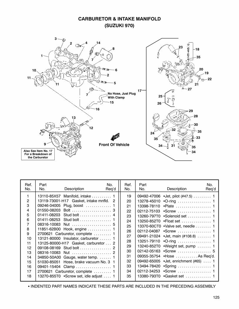
125
1 13110-85X57 Manifold, intake 1. . . . . . . . . .2 13119-73001-H17 Gasket, intake mnfld. 23 09246-04005 Plug, boost 1. . . . . . . . . . . . .4 01550-08203 Bolt 3. . . . . . . . . . . . . . . . . . . .5 01411-08203 Stud bolt 4. . . . . . . . . . . . . . . .
6 01411-08253 Stud bolt 1. . . . . . . . . . . . . . . .7 08316-10083 Nut 5. . . . . . . . . . . . . . . . . . . .8 11851-62B00 Hook, engine 1. . . . . . . . . . . .9 2700621 Carburetor, complete 1. . . . . . . . .10 13121-80000 Insulator, carburetor 1. . . . . .
11 13125-80000-H17 Gasket, carburetor 2. . .12 09108-08169 Stud bolt 2. . . . . . . . . . . . . . . .13 08316-10083 Nut 2. . . . . . . . . . . . . . . . . . . .14 34850-50A00 Gauge, water temp. 1. . . . . .15 51030-85051 Hose, brake vacuum No. 3 116 09401-15404 Clamp 1. . . . . . . . . . . . . . . . . .
17 2700621 Carburetor, complete 1. . . . . . . . .18 13270-855T0 Screw set, idle adjust 1. . . .
19 09492-47006 Jet, pilot (#47.5) 1. . . . . . . . .
20 13278-45010 O-ring 1. . . . . . . . . . . . . . . . .
21 13398-78110 Plate 1. . . . . . . . . . . . . . . . . .
22 02112-75103 Screw 1. . . . . . . . . . . . . . . . .
23 13260-797T0 Solenoid set 1. . . . . . . . . . . .
24 13250-852T0 Float set 1. . . . . . . . . . . . . . .
25 13370-60CT0 Valve set, needle 1. . . . . . . .
26 02112-04087 Screw 1. . . . . . . . . . . . . . . . .
27 09491-21024 Jet, main (#108.8) 1. . . . . . .
28 13251-79110 O-ring 1. . . . . . . . . . . . . . . . .
29 13240-852T0 Weight set, pump 1. . . . . . .
30 02142-05163 Screw 5. . . . . . . . . . . . . . . . .
31 09355-35754 Hose As Req’d.. . . . . . . . . . .
32 09492-65005 Jet, enrichment (#65) 1. . . .
33 13494-78420 Spring 1. . . . . . . . . . . . . . . . .
34 02112-34253 Screw 1. . . . . . . . . . . . . . . . .
35 13380-793T0 Gasket set 1. . . . . . . . . . . . .
Ref.No.
PartNo. Description
No.Req’d
No.Req’dDescription
PartNo.
Ref.No.
CARBURETOR & INTAKE MANIFOLD
(SUZUKI 970)
11
10
8
21
9
15
4
20
3
13
25
14
19
17
16
5
6
12
7
18
22
23
24
7
11
2
1
2
INDENTED PART NAMES INDICATE THESE PARTS ARE INCLUDED IN THE PRECEDING ASSEMBLY
35
26
27
28
29
30
35
33
35
34
34 31
35
32
Also See Item No. 17For a Breakdown ofthe Carburetor
Front Of Vehicle
No Hose, Just Plug
With Clamp
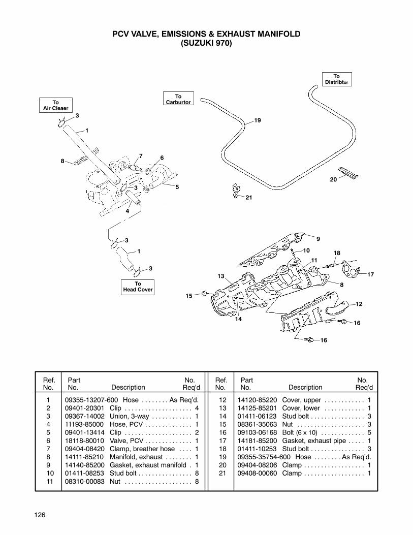
126
1 09355-13207-600 Hose As Req’d.. . . . . . . .2 09401-20301 Clip 4. . . . . . . . . . . . . . . . . . . .3 09367-14002 Union, 3-way 1. . . . . . . . . . . .4 11193-85000 Hose, PCV 1. . . . . . . . . . . . . .5 09401-13414 Clip 2. . . . . . . . . . . . . . . . . . . .
6 18118-80010 Valve, PCV 1. . . . . . . . . . . . . .7 09404-08420 Clamp, breather hose 1. . . .8 14111-85210 Manifold, exhaust 1. . . . . . . .9 14140-85200 Gasket, exhaust manifold 1.10 01411-08253 Stud bolt 8. . . . . . . . . . . . . . . .
11 08310-00083 Nut 8. . . . . . . . . . . . . . . . . . . .
12 14120-85220 Cover, upper 1. . . . . . . . . . . .13 14125-85201 Cover, lower 1. . . . . . . . . . . .14 01411-06123 Stud bolt 3. . . . . . . . . . . . . . . .15 08361-35063 Nut 3. . . . . . . . . . . . . . . . . . . .16 09103-06168 Bolt (6 x 10) 5. . . . . . . . . . . . .
17 14181-85200 Gasket, exhaust pipe 1. . . . .18 01411-10253 Stud bolt 3. . . . . . . . . . . . . . . .19 09355-35754-600 Hose As Req’d.. . . . . . . .20 09404-08206 Clamp 1. . . . . . . . . . . . . . . . . .21 09408-00060 Clamp 1. . . . . . . . . . . . . . . . . .
Ref.No.
PartNo. Description
No.Req’d
No.Req’dDescription
PartNo.
Ref.No.
PCV VALVE, EMISSIONS & EXHAUST MANIFOLD(SUZUKI 970)
1
7 6
5
4
3
1
8
3
3
3
8
9
10
11
18
17
16
16
12
14
15
13
ToAir Cleaer
ToHead Cover
19
20
21
ToDistribtor
ToCarburtor
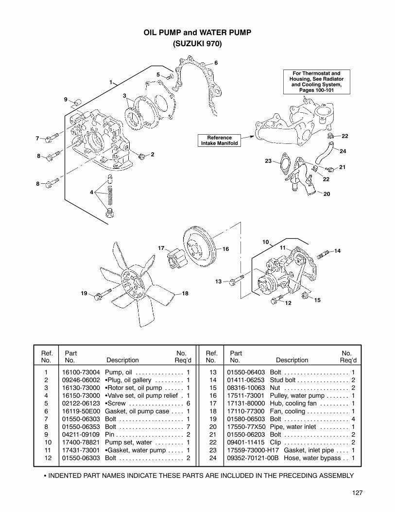
127
1 16100-73004 Pump, oil 1. . . . . . . . . . . . . . .2 09246-06002 Plug, oil gallery 1. . . . . . . . .3 16130-73000 Rotor set, oil pump 1. . . . . .4 16150-73000 Valve set, oil pump relief 1.5 02122-06123 Screw 6. . . . . . . . . . . . . . . . .
6 16119-50E00 Gasket, oil pump case 1. . . .7 01550-06303 Bolt 1. . . . . . . . . . . . . . . . . . . .8 01550-06353 Bolt 7. . . . . . . . . . . . . . . . . . . .9 04211-09109 Pin 2. . . . . . . . . . . . . . . . . . . . .10 17400-78821 Pump set, water 1. . . . . . . . .
11 17431-73001 Gasket, water pump 1. . . . .12 01550-06303 Bolt 2. . . . . . . . . . . . . . . . . . . .
13 01550-06403 Bolt 1. . . . . . . . . . . . . . . . . . . .14 01411-06253 Stud bolt 2. . . . . . . . . . . . . . . .15 08316-10063 Nut 2. . . . . . . . . . . . . . . . . . . .16 17511-73001 Pulley, water pump 1. . . . . . .17 17131-80000 Hub, cooling fan 1. . . . . . . . .
18 17110-77300 Fan, cooling 1. . . . . . . . . . . . .19 01580-06503 Bolt 4. . . . . . . . . . . . . . . . . . . .20 17550-77X50 Pipe, water inlet 1. . . . . . . . .21 01550-06203 Bolt 2. . . . . . . . . . . . . . . . . . . .22 09401-11415 Clip 2. . . . . . . . . . . . . . . . . . . .
23 17559-73000-H17 Gasket, inlet pipe 1. . . .24 09352-70121-00B Hose, water bypass 1. .
Ref.No.
PartNo. Description
No.Req’d
No.Req’dDescription
PartNo.
Ref.No.
OIL PUMP and WATER PUMP
(SUZUKI 970)
INDENTED PART NAMES INDICATE THESE PARTS ARE INCLUDED IN THE PRECEDING ASSEMBLY
4
3
2
6
7
8
9
5
1
8
1011
12
13
14
15
1617
1819
22
24
21
22
20
23
ReferenceIntake Manifold
For Thermostat andHousing, See Radiatorand Cooling System,
Pages 100-101
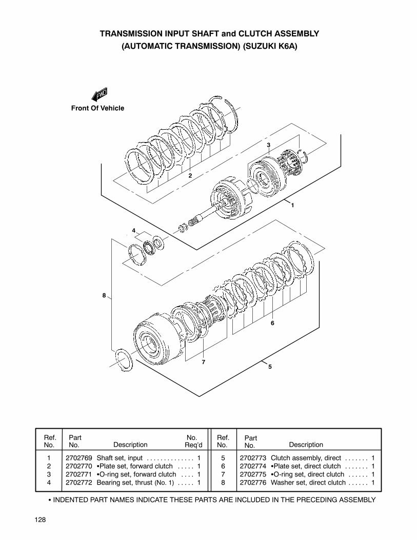
128
TRANSMISSION INPUT SHAFT and CLUTCH ASSEMBLY
(AUTOMATIC TRANSMISSION) (SUZUKI K6A)
7
6
5
8
1
2
4
3
Front Of Vehicle
Ref.No.
PartNo. Description
No.Req’d Description
PartNo.
Ref.No.
1 2702769 Shaft set, input 1. . . . . . . . . . . . . .2 2702770 Plate set, forward clutch 1. . . . .3 2702771 O-ring set, forward clutch 1. . . .4 2702772 Bearing set, thrust (No. 1) 1. . . . .
5 2702773 Clutch assembly, direct 1. . . . . . .6 2702774 Plate set, direct clutch 1. . . . . . .7 2702775 O-ring set, direct clutch 1. . . . . .8 2702776 Washer set, direct clutch 1. . . . . .
INDENTED PART NAMES INDICATE THESE PARTS ARE INCLUDED IN THE PRECEDING ASSEMBLY
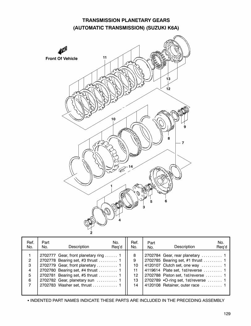
129
TRANSMISSION PLANETARY GEARS
(AUTOMATIC TRANSMISSION) (SUZUKI K6A)
Ref.No.
PartNo. Description
No.Req’d
No.Req’dDescription
PartNo.
Ref.No.
INDENTED PART NAMES INDICATE THESE PARTS ARE INCLUDED IN THE PRECEDING ASSEMBLY
1 2702777 Gear, front planetary ring 1. . . . . .2 2702778 Bearing set, #3 thrust 1. . . . . . . . .3 2702779 Gear, front planetary 1. . . . . . . . . .4 2702780 Bearing set, #4 thrust 1. . . . . . . . .
5 2702781 Bearing set, #5 thrust 1. . . . . . . . .6 2702782 Gear, planetary sun 1. . . . . . . . . .7 2702783 Washer set, thrust 1. . . . . . . . . . . .
8 2702784 Gear, rear planetary 1. . . . . . . . . .9 2702785 Bearing set, #1 thrust 1. . . . . . . . .10 4120107 Clutch set, one way 1. . . . . . . . . .11 4119614 Plate set, 1st/reverse 1. . . . . . . . .
12 2702788 Piston set, 1st/reverse 1. . . . . . . .13 2702789 O-ring set, 1st/reverse 1. . . . . . .14 4120108 Retainer, outer race 1. . . . . . . . . .
Front Of Vehicle 11
13
12
10
14
8
9
7
1
2
4
3
5 6
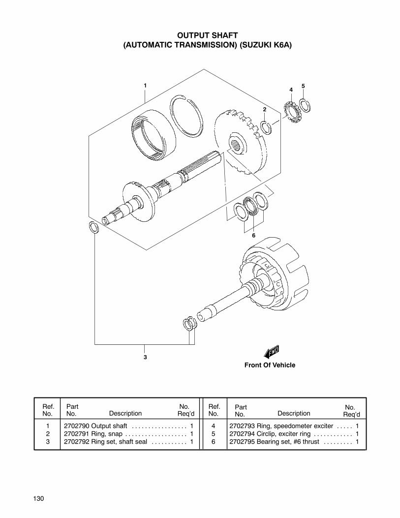
130
OUTPUT SHAFT
(AUTOMATIC TRANSMISSION) (SUZUKI K6A)
Ref.No.
PartNo. Description
No.Req’d
No.Req’dDescription
PartNo.
Ref.No.
1 2702790 Output shaft 1. . . . . . . . . . . . . . . . .2 2702791 Ring, snap 1. . . . . . . . . . . . . . . . . . .3 2702792 Ring set, shaft seal 1. . . . . . . . . . .
4 2702793 Ring, speedometer exciter 1. . . . .5 2702794 Circlip, exciter ring 1. . . . . . . . . . . .6 2702795 Bearing set, #6 thrust 1. . . . . . . . .
Front Of Vehicle
14
5
2
6
3
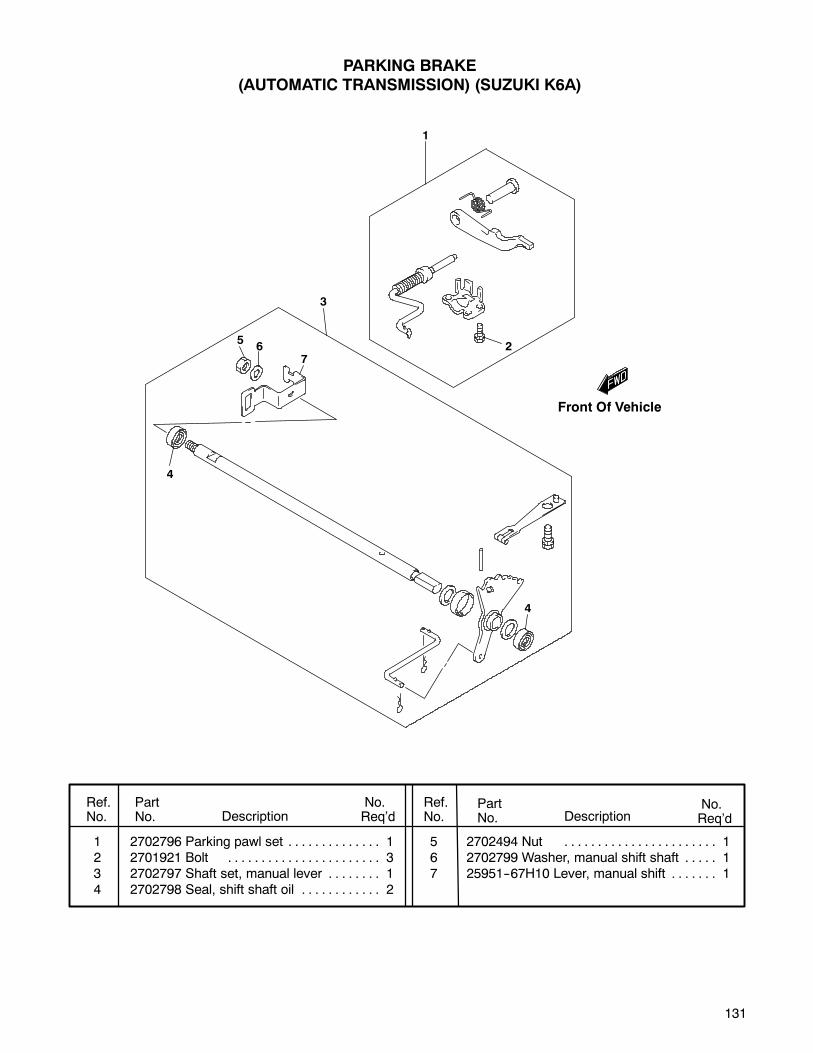
131
Front Of Vehicle
PARKING BRAKE
(AUTOMATIC TRANSMISSION) (SUZUKI K6A)
Ref.No.
PartNo. Description
No.Req’d
No.Req’dDescription
PartNo.
Ref.No.
1 2702796 Parking pawl set 1. . . . . . . . . . . . . .2 2701921 Bolt 3. . . . . . . . . . . . . . . . . . . . . . .3 2702797 Shaft set, manual lever 1. . . . . . . .4 2702798 Seal, shift shaft oil 2. . . . . . . . . . . .
5 2702494 Nut 1. . . . . . . . . . . . . . . . . . . . . . .6 2702799 Washer, manual shift shaft 1. . . . .7 25951--67H10 Lever, manual shift 1. . . . . . .
1
3
65
4
7
4
2

132
BRAKE BAND
(AUTOMATIC TRANSMISSION) (SUZUKI K6A)
Ref.No.
PartNo. Description
No.Req’d
No.Req’dDescription
PartNo.
Ref.No.
1 2702800 Band set, 2nd brake 1. . . . . . . . . . .2 4120109 Piston AY, 2nd brake 1. . . . . . . . . .3 2702803 Sealing set, 2nd brake 1. . . . . . . . .
4 2702804 Cover set, 2nd brake piston 1. . . .5 2702805 Spring, 2nd brake piston 1. . . . . . .
Front Of Vehicle
5
3
4
2
1
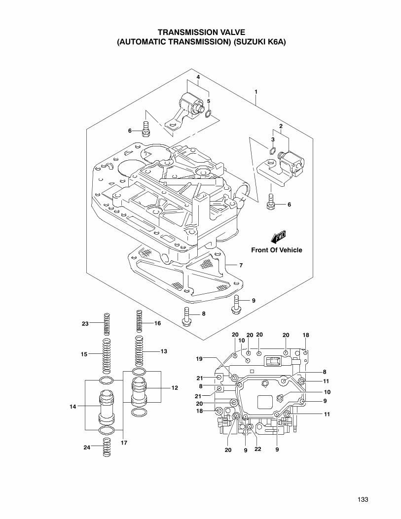
133
TRANSMISSION VALVE
(AUTOMATIC TRANSMISSION) (SUZUKI K6A)
Front Of Vehicle
1
4
6
5
2
3
6
7
9
8
23
15
16
13
12
2417
14
2010
20 20 20 18
8
11
10
9
11
922920
18
20
21
8
21
19
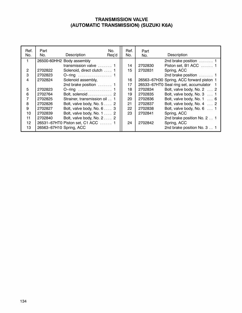
134
Ref.No.
PartNo. Description
No.Req’d Description
PartNo.
Ref.No.
1 26500-60HH2 Body assemblytransmission valve 1. . . . . . .
2 2702822 Solenoid, direct clutch 1. . . .3 2702823 O--ring 1. . . . . . . . . . . . . . . . .
4 2702824 Solenoid assembly,2nd brake position 1. . . . . . .
5 2702823 O--ring 1. . . . . . . . . . . . . . . . .6 2702764 Bolt, solenoid 2. . . . . . . . . . . .7 2702825 Strainer, transmission oil 1. .
8 2702826 Bolt, valve body, No. 5 2. . . .9 2702827 Bolt, valve body, No. 6 3. . . .10 2702839 Bolt, valve body, No. 1 2. . . .11 2702840 Bolt, valve body, No. 2 2. . . .
12 26531--67HT0 Piston set, C1 ACC 1. . . . . .13 26563--67H10 Spring, ACC
2nd brake position 1. . . . . . .14 2702830 Piston set, B1 ACC 1. . . . . .15 2702831 Spring, ACC
2nd brake position 1. . . . . . .
16 26563--67H30 Spring, ACC forward piston 117 26533--67HT0 Seal ring set, accumulator 118 2702834 Bolt, valve body, No. 2 2. . .19 2702835 Bolt, valve body, No. 3 1. . .20 2702836 Bolt, valve body, No. 1 6. . .
21 2702837 Bolt, valve body, No. 4 2. . .22 2702838 Bolt, valve body, No. 6 1. . .23 2702841 Spring, ACC
2nd brake position No. 2 1. .
24 2702842 Spring, ACC2nd brake position No. 3 1. .
TRANSMISSION VALVE
(AUTOMATIC TRANSMISSION) (SUZUKI K6A)
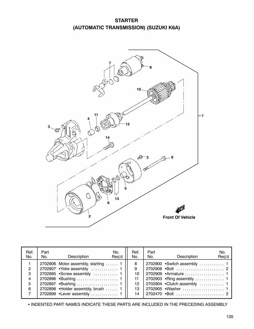
135
Ref.No.
PartNo. Description
No.Req’d
No.Req’dDescription
PartNo.
Ref.No.
STARTER
(AUTOMATIC TRANSMISSION) (SUZUKI K6A)
INDENTED PART NAMES INDICATE THESE PARTS ARE INCLUDED IN THE PRECEDING ASSEMBLY
1 2702906 Motor assembly, starting 1. . . . . .2 2702907 Yoke assembly 1. . . . . . . . . . . . .3 2702895 Screw assembly 1. . . . . . . . . . . .4 2702896 Bushing 1. . . . . . . . . . . . . . . . . . . .
5 2702897 Bushing 1. . . . . . . . . . . . . . . . . . . .6 2702898 Holder assembly, brush 1. . . . . .7 2702899 Lever assembly 1. . . . . . . . . . . . .
8 2702900 Switch assembly 1. . . . . . . . . . . .9 2702908 Bolt 2. . . . . . . . . . . . . . . . . . . . . . .10 2702909 Armature 1. . . . . . . . . . . . . . . . . . .11 2702903 Ring assembly 1. . . . . . . . . . . . . .
12 2702904 Clutch assembly 1. . . . . . . . . . . .13 2702905 Washer 1. . . . . . . . . . . . . . . . . . . .14 2702470 Bolt 2. . . . . . . . . . . . . . . . . . . . . . .
1
87
10
12
114
3
14
2
613
5
3 9
Front Of Vehicle

136
Ref.No.
PartNo. Description
No.Req’d
No.Req’dDescription
PartNo.
Ref.No.
DISTRIBUTOR (SUZUKI K6A)
INDENTED PART NAMES INDICATE THESE PARTS ARE INCLUDED IN THE PRECEDING ASSEMBLY
1 33100-51F11 Distributor, complete 1. . . . .2 33321-50F50 Cap, distributor 1. . . . . . . . .3 33278-85060 O-ring 1. . . . . . . . . . . . . . . . .4 33310-51F10 Rotor 1. . . . . . . . . . . . . . . . . .5 33326-51F10 Shield, dust 1. . . . . . . . . . . .6 33140-64B70 Coil, pick-up 1. . . . . . . . . . . .7 33151-86240 Screw 2. . . . . . . . . . . . . . . . .8 33152-64B70 Screw 2. . . . . . . . . . . . . . . . .9 33375-62D10 Connector 1. . . . . . . . . . . . .10 33152-64B70 Screw 2. . . . . . . . . . . . . . . . .11 33370-76D20 Igniter assembly 1. . . . . . . .12 02112-34103 Screw 2. . . . . . . . . . . . . . . .13 33187-50F10 Screw 2. . . . . . . . . . . . . . . .
14 33180-62D10 Breaker assembly 1. . . . . . .15 33230-51F10 Controller, vacuum 1. . . . . .16 08332-11033 E-ring 1. . . . . . . . . . . . . . . . .17 33151-60B40 Screw 2. . . . . . . . . . . . . . . .18 09138-08003 Screw 1. . . . . . . . . . . . . . . . . .19 33410-50F20 Coil, ignition 1. . . . . . . . . . . . .20 33710-60C21 Cord, high tension (No. 1) 1.21 33705-60C11 Cord set, high tension 1. . . .22 33884-86510 Clamp 1. . . . . . . . . . . . . . . . . .23 33881-60C11 Bracket 1. . . . . . . . . . . . . . . . .24 02112-06083 Screw 1. . . . . . . . . . . . . . . . . .25 33460-50F30 Hose, distributor cap 1. . . . .26 09408-00013 Clip 1. . . . . . . . . . . . . . . . . . . .
22
23
24
21
26
19
25
4
5
10
9
786
1211
14
13
16 17
15
18
3
1
2
Front Of Vehicle
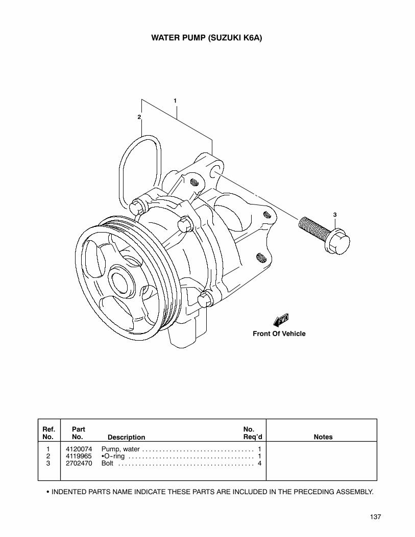
137
Ref.No.
PartNo. Description Notes
No.Req’d
1 4120074 Pump, water 1. . . . . . . . . . . . . . . . . . . . . . . . . . . . . . . . .2 4119965 O--ring 1. . . . . . . . . . . . . . . . . . . . . . . . . . . . . . . . . . . . .3 2702470 Bolt 4. . . . . . . . . . . . . . . . . . . . . . . . . . . . . . . . . . . . . . . .
INDENTED PARTS NAME INDICATE THESE PARTS ARE INCLUDED IN THE PRECEDING ASSEMBLY.
WATER PUMP (SUZUKI K6A)
2
1
3
Front Of Vehicle

138
1 4120076 Cap, water thermostat 1. . . . . . . . . . . . . . . . . . . . . . .2 2702540 Union, air vent 1. . . . . . . . . . . . . . . . . . . . . . . . . . . . . .3 4120077 Cap, water outlet 1. . . . . . . . . . . . . . . . . . . . . . . . . . . .4 4120078 Hose, water engine outlet 1. . . . . . . . . . . . . . . . . . . .5 4120079 Thermostat, water 1. . . . . . . . . . . . . . . . . . . . . . . . . . .6 4119967 Gasket, thermo case 1. . . . . . . . . . . . . . . . . . . . . . . .7 4119609 O--ring, water inlet pipe 1. . . . . . . . . . . . . . . . . . . . . .8 4120081 Pipe, water inlet 1. . . . . . . . . . . . . . . . . . . . . . . . . . . . .9 2702541 Gasket, air vent union 1. . . . . . . . . . . . . . . . . . . . . . .10 4120082 Clip, water hose 2. . . . . . . . . . . . . . . . . . . . . . . . . . . . .11 4120083 Stud bolt, outlet cap 2. . . . . . . . . . . . . . . . . . . . . . . . .12 2702486 Bolt, water inlet pipe 2. . . . . . . . . . . . . . . . . . . . . . . . .13 2702469 Bolt, thermostat cap 2. . . . . . . . . . . . . . . . . . . . . . . . .14 4120084 Bolt, water outlet cap 1. . . . . . . . . . . . . . . . . . . . . . . .15 2703002 Nut, water outlet cap 2. . . . . . . . . . . . . . . . . . . . . . . . .16 2702481 Sensor, water temperature 1. . . . . . . . . . . . . . . . . . .
Ref.No.
PartNo. Description Notes
No.Req’d
1
2
3
4
5
6
7
8
9
10
11
12
13
14
15
16
10
12
WATER HOSE (SUZUKI K6A)
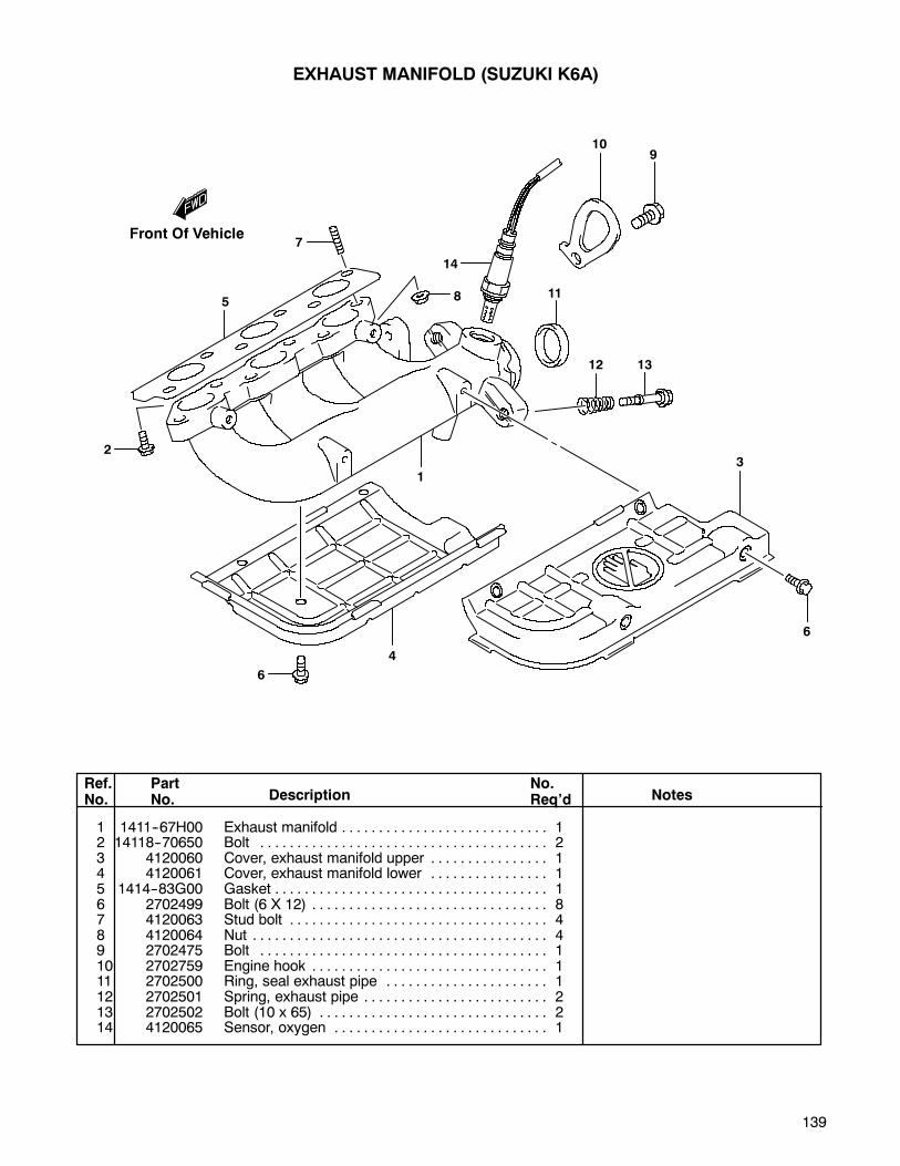
139
1 1411--67H00 Exhaust manifold 1. . . . . . . . . . . . . . . . . . . . . . . . . . . .2 14118--70650 Bolt 2. . . . . . . . . . . . . . . . . . . . . . . . . . . . . . . . . . . . . . .3 4120060 Cover, exhaust manifold upper 1. . . . . . . . . . . . . . . .4 4120061 Cover, exhaust manifold lower 1. . . . . . . . . . . . . . . .5 1414--83G00 Gasket 1. . . . . . . . . . . . . . . . . . . . . . . . . . . . . . . . . . . . .6 2702499 Bolt (6 X 12) 8. . . . . . . . . . . . . . . . . . . . . . . . . . . . . . . .7 4120063 Stud bolt 4. . . . . . . . . . . . . . . . . . . . . . . . . . . . . . . . . . .8 4120064 Nut 4. . . . . . . . . . . . . . . . . . . . . . . . . . . . . . . . . . . . . . . .9 2702475 Bolt 1. . . . . . . . . . . . . . . . . . . . . . . . . . . . . . . . . . . . . . .10 2702759 Engine hook 1. . . . . . . . . . . . . . . . . . . . . . . . . . . . . . . .11 2702500 Ring, seal exhaust pipe 1. . . . . . . . . . . . . . . . . . . . . .12 2702501 Spring, exhaust pipe 2. . . . . . . . . . . . . . . . . . . . . . . . .13 2702502 Bolt (10 x 65) 2. . . . . . . . . . . . . . . . . . . . . . . . . . . . . . .14 4120065 Sensor, oxygen 1. . . . . . . . . . . . . . . . . . . . . . . . . . . . .
Ref.No.
PartNo. Description Notes
No.Req’d
EXHAUST MANIFOLD (SUZUKI K6A)
10
Front Of Vehicle
9
7
5
2
1
14
8 11
1312
3
6
4
6
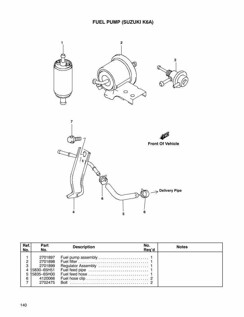
140
1 2701897 Fuel pump assembly 1. . . . . . . . . . . . . . . . . . . . . . . . .2 2701898 Fuel filter 1. . . . . . . . . . . . . . . . . . . . . . . . . . . . . . . . . . .3 2701899 Regulator Assembly 1. . . . . . . . . . . . . . . . . . . . . . . . .4 15830--65H51 Fuel feed pipe 1. . . . . . . . . . . . . . . . . . . . . . . . . . . . . .5 15835--65H00 Fuel feed hose 1. . . . . . . . . . . . . . . . . . . . . . . . . . . . . .6 4120066 Fuel hose clip 2. . . . . . . . . . . . . . . . . . . . . . . . . . . . . . .7 2702475 Bolt 2. . . . . . . . . . . . . . . . . . . . . . . . . . . . . . . . . . . . . . .
Ref.No.
PartNo.
Description NotesNo.Req’d
FUEL PUMP (SUZUKI K6A)
Front Of Vehicle
1 2
3
7
4
6
56
Delivery Pipe

141
DELIVERY PIPE (SUZUKI K6A)
Front Of Vehicle
1 4120067 Delivery pipe 1. . . . . . . . . . . . . . . . . . . . . . . . . . . . . . .2 2702486 Bolt 1. . . . . . . . . . . . . . . . . . . . . . . . . . . . . . . . . . . . . . .3 2701978 Bolt 2. . . . . . . . . . . . . . . . . . . . . . . . . . . . . . . . . . . . . . .4 15710--65H00 Injector assembly, fuel 3. . . . . . . . . . . . . . . . . . . . . . .5 2702512 Grommet set 3. . . . . . . . . . . . . . . . . . . . . . . . . . . .6 2702513 Cushion 3. . . . . . . . . . . . . . . . . . . . . . . . . . . . . . . . . . . .7 2702514 Clamp 1. . . . . . . . . . . . . . . . . . . . . . . . . . . . . . . . . . . . .
Ref.No.
PartNo.
Description NotesNo.Req’d
1
3
2
7
5
4
6
• INDENTED PART NAMES INDICATE THESE PARTS ARE INCLUDED IN THE PRECEDING ASSEMBLY.
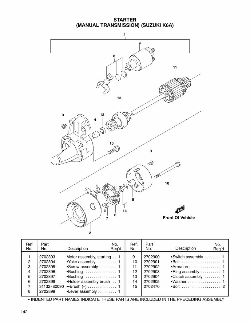
142
1 2702893 Motor assembly, starting 1. .2 2702894 Yoke assembly 1. . . . . . . . .3 2702895 Screw assembly 1. . . . . . . .4 2702896 Bushing 1. . . . . . . . . . . . . . .5 2702897 Bushing 1. . . . . . . . . . . . . . .
6 2702898 Holder assembly brush 1. .7 31132--80090 Brush (--) 1. . . . . . . . . . . . . .8 2702899 Lever assembly 1. . . . . . . . .
9 2702900 Switch assembly 1. . . . . . . .10 2702901 Bolt 1. . . . . . . . . . . . . . . . . . .11 2702902 Armature 1. . . . . . . . . . . . . .12 2702903 Ring assembly 1. . . . . . . . . .13 2702904 Clutch assembly 1. . . . . . . .
14 2702905 Washer 1. . . . . . . . . . . . . . . .15 2702470 Bolt 2. . . . . . . . . . . . . . . . . . .
Ref.No.
PartNo. Description
No.Req’d
No.Req’dDescription
PartNo.
Ref.No.
STARTER(MANUAL TRANSMISSION) (SUZUKI K6A)
INDENTED PART NAMES INDICATE THESE PARTS ARE INCLUDED IN THE PRECEDING ASSEMBLY
1
Front Of Vehicle
8
9
11
13
12
4
3
15
3
10
5
146
7
2
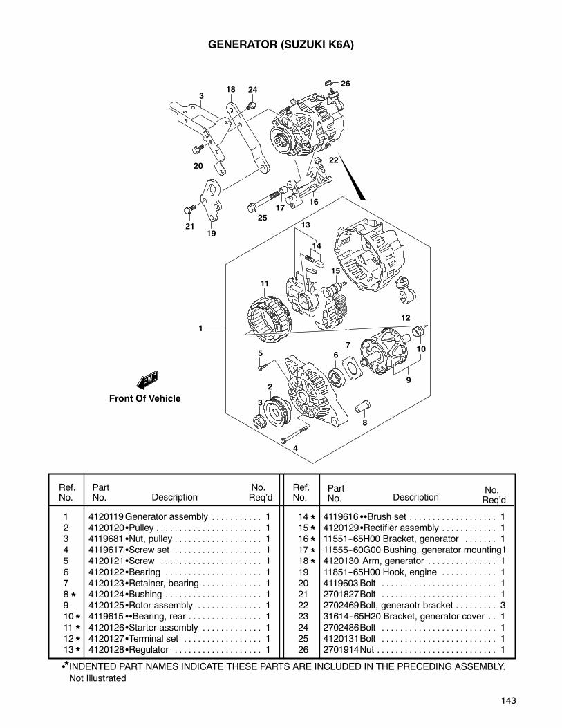
143
Ref.No.
PartNo. Description
No.Req’d
No.Req’dDescription
PartNo.
Ref.No.
1 4120119Generator assembly 1. . . . . . . . . . .2 4120120 Pulley 1. . . . . . . . . . . . . . . . . . . . . . .3 4119681 Nut, pulley 1. . . . . . . . . . . . . . . . . . .4 4119617 Screw set 1. . . . . . . . . . . . . . . . . . .5 4120121 Screw 1. . . . . . . . . . . . . . . . . . . . . .
6 4120122 Bearing 1. . . . . . . . . . . . . . . . . . . . .7 4120123 Retainer, bearing 1. . . . . . . . . . . . .8 4120124 Bushing 1. . . . . . . . . . . . . . . . . . . . .9 4120125 Rotor assembly 1. . . . . . . . . . . . . .10 4119615 Bearing, rear 1. . . . . . . . . . . . . . . .
11 4120126 Starter assembly 1. . . . . . . . . . . . .12 4120127 Terminal set 1. . . . . . . . . . . . . . . . .13 4120128 Regulator 1. . . . . . . . . . . . . . . . . . .
14 4119616 Brush set 1. . . . . . . . . . . . . . . . . . .15 4120129 Rectifier assembly 1. . . . . . . . . . . .16 11551--65H00 Bracket, generator 1. . . . . . .17 11555--60G00 Bushing, generator mounting118 4120130 Arm, generator 1. . . . . . . . . . . . . . .
19 11851--65H00 Hook, engine 1. . . . . . . . . . . .20 4119603Bolt 1. . . . . . . . . . . . . . . . . . . . . . . . .21 2701827Bolt 1. . . . . . . . . . . . . . . . . . . . . . . . .22 2702469Bolt, generaotr bracket 3. . . . . . . . .23 31614--65H20 Bracket, generator cover 1. .
24 2702486Bolt 1. . . . . . . . . . . . . . . . . . . . . . . . .25 4120131Bolt 1. . . . . . . . . . . . . . . . . . . . . . . . .26 2701914Nut 1. . . . . . . . . . . . . . . . . . . . . . . . . .
Not Illustrated
INDENTED PART NAMES INDICATE THESE PARTS ARE INCLUDED IN THE PRECEDING ASSEMBLY.
GENERATOR (SUZUKI K6A)
*
****
*****
*
Front Of Vehicle
318 24
20
2119
25
1716
22
26
13
15
14
11
1
5
2
3
4
8
6
7
9
10
12
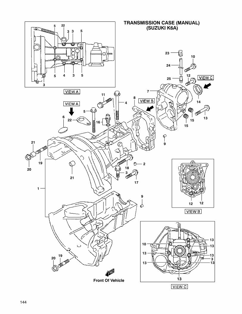
144
1
2
3
45
6
7
8
9
10
11
12
13
14
1516
17
18
19
20
21
22
23
24
25
5
33
3 5
21
22
5
4
15
3
9
2019
12 12
10
3
13
13
13
13
13
13
13
TRANSMISSION CASE (MANUAL)(SUZUKI K6A)
5
Front Of Vehicle
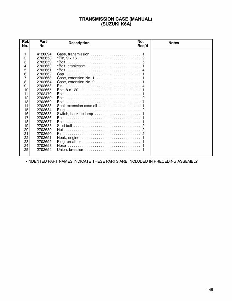
145
1 4120094 Case, transmission 1. . . . . . . . . . . . . . . . . . . . . . . . . .2 2702658 •Pin, 9 x 16 2. . . . . . . . . . . . . . . . . . . . . . . . . . . . . . . . .3 2702659 •Bolt 5. . . . . . . . . . . . . . . . . . . . . . . . . . . . . . . . . . . . . . .4 2702660 •Bolt, crankcase 1. . . . . . . . . . . . . . . . . . . . . . . . . . . .5 2702661 •Bolt 4. . . . . . . . . . . . . . . . . . . . . . . . . . . . . . . . . . . . . . .6 2702662 Cap 1. . . . . . . . . . . . . . . . . . . . . . . . . . . . . . . . . . . . . . .7 2702663 Case, extension No. 1 1. . . . . . . . . . . . . . . . . . . . . . .8 2702664 Case, extension No. 2 1. . . . . . . . . . . . . . . . . . . . . . .9 2702658 Pin 4. . . . . . . . . . . . . . . . . . . . . . . . . . . . . . . . . . . . . . . .10 2702665 Bolt, 8 x 120 1. . . . . . . . . . . . . . . . . . . . . . . . . . . . . . . .11 2702470 Bolt 1. . . . . . . . . . . . . . . . . . . . . . . . . . . . . . . . . . . . . . .12 2702659 Bolt 2. . . . . . . . . . . . . . . . . . . . . . . . . . . . . . . . . . . . . . .13 2702660 Bolt 7. . . . . . . . . . . . . . . . . . . . . . . . . . . . . . . . . . . . . . .14 2702683 Seal, extension case oil 1. . . . . . . . . . . . . . . . . . . . . .15 2702684 Plug 2. . . . . . . . . . . . . . . . . . . . . . . . . . . . . . . . . . . . . . .16 2702685 Switch, back up lamp 1. . . . . . . . . . . . . . . . . . . . . . . .17 2702686 Bolt 1. . . . . . . . . . . . . . . . . . . . . . . . . . . . . . . . . . . . . . .18 2702687 Bolt 1. . . . . . . . . . . . . . . . . . . . . . . . . . . . . . . . . . . . . . .19 2702688 Stud bolt 2. . . . . . . . . . . . . . . . . . . . . . . . . . . . . . . . . . .20 2702689 Nut 2. . . . . . . . . . . . . . . . . . . . . . . . . . . . . . . . . . . . . . . .21 2702690 Pin 2. . . . . . . . . . . . . . . . . . . . . . . . . . . . . . . . . . . . . . . .22 2702691 Hook, engine 1. . . . . . . . . . . . . . . . . . . . . . . . . . . . . . .23 2702692 Plug, breather 1. . . . . . . . . . . . . . . . . . . . . . . . . . . . . .24 2702693 Hose 1. . . . . . . . . . . . . . . . . . . . . . . . . . . . . . . . . . . . . .25 2702694 Union, breather 1. . . . . . . . . . . . . . . . . . . . . . . . . . . . .
Ref.No.
PartNo.
Description NotesNo.Req’d
•INDENTED PART NAMES INDICATE THESE PARTS ARE INCLUDED IN PRECEDING ASSEMBLY.
TRANSMISSION CASE (MANUAL)(SUZUKI K6A)

146
1
2
3
4
5
6
7
8
ENGINE GASKETS (SUZUKI K6A)
Front Of Vehicle
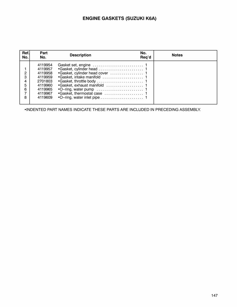
147
4119954 Gasket set, engine 1. . . . . . . . . . . . . . . . . . . . . . . . . .1 4119957 •Gasket, cylinder head 1. . . . . . . . . . . . . . . . . . . . . . .2 4119958 •Gasket, cylinder head cover 1. . . . . . . . . . . . . . . . .3 4119959 •Gasket, intake manifold 1. . . . . . . . . . . . . . . . . . . . .4 2701803 •Gasket, throttle body 1. . . . . . . . . . . . . . . . . . . . . . . .5 4119960 •Gasket, exhaust manifold 1. . . . . . . . . . . . . . . . . . .6 4119965 •O--ring, water pump 1. . . . . . . . . . . . . . . . . . . . . . . .7 4119967 •Gasket, thermostat case 1. . . . . . . . . . . . . . . . . . . .8 4119609 •O--ring, water inlet pipe 1. . . . . . . . . . . . . . . . . . . . . .
•INDENTED PART NAMES INDICATE THESE PARTS ARE INCLUDED IN PRECEDING ASSEMBLY.
Ref.No.
PartNo.
Description NotesNo.Req’d
ENGINE GASKETS (SUZUKI K6A)

148
1
2
3
4
5
6
7
8
9
10
11
12
13
14
15
1617
CYLINDER HEAD and COMPONENTS (SUZUKI K6A)
Front Of Vehicle

149
1 4119962 Head, cylinder 1. . . . . . . . . . . . . . . . . . . . . . . . . . . . . .2 4119963 •Guide, valve 12. . . . . . . . . . . . . . . . . . . . . . . . . . . . . .3 2701816 •Plug 2. . . . . . . . . . . . . . . . . . . . . . . . . . . . . . . . . . . . . .4 4119964 •Bolt 17. . . . . . . . . . . . . . . . . . . . . . . . . . . . . . . . . . . . . .5 2701821 •Pin 14. . . . . . . . . . . . . . . . . . . . . . . . . . . . . . . . . . . . . .6 4119956 Bolt, cylinder head 8. . . . . . . . . . . . . . . . . . . . . . . . . . .7 4119966 Pin 2. . . . . . . . . . . . . . . . . . . . . . . . . . . . . . . . . . . . . . . .8 4119957 Gasket, cylinder head 1. . . . . . . . . . . . . . . . . . . . . . . .9 4119968 Cover, cylinder head 1. . . . . . . . . . . . . . . . . . . . . . . . .10 4119958 Gasket, head upper cover 1. . . . . . . . . . . . . . . . . . . .11 4119970 Bolt 5. . . . . . . . . . . . . . . . . . . . . . . . . . . . . . . . . . . . . . .12 4119971 Bolt 1. . . . . . . . . . . . . . . . . . . . . . . . . . . . . . . . . . . . . . .13 4119972 Gasket, spark plug hole 3. . . . . . . . . . . . . . . . . . . . . .14 4119973 Cap, oil filler 1. . . . . . . . . . . . . . . . . . . . . . . . . . . . . . . .15 4119606 Spark plug 3 NGK, 3932. . . . . . . . . . . . . . . . . . . . . . . . . . . . . . . . .16 4117894 Cover, cylinder head, upper 1. . . . . . . . . . . . . . . . . . .17 4117892 Bolt 4. . . . . . . . . . . . . . . . . . . . . . . . . . . . . . . . . . . . . . .
•INDENTED PART NAMES INDICATE THESE PARTS ARE INCLUDED IN PRECEDING ASSEMBLY.
Ref.No.
PartNo.
Description NotesNo.Req’d
CYLINDER HEAD and COMPONENTS (SUZUKI K6A)
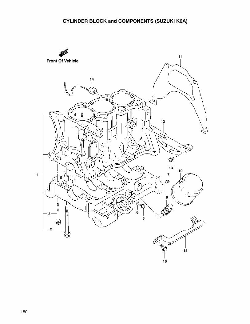
150
1
2
3
4
5
6
78
9
10
11
12
13
14
15
16
CYLINDER BLOCK and COMPONENTS (SUZUKI K6A)
Front Of Vehicle
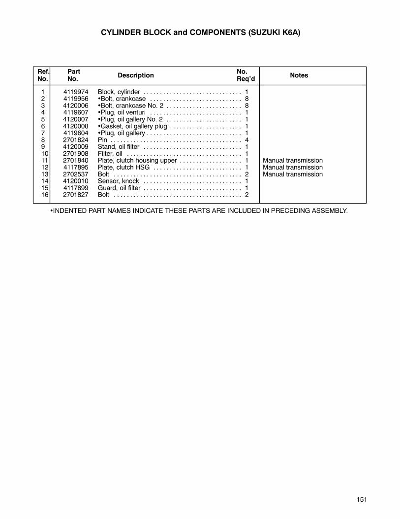
151
1 4119974 Block, cylinder 1. . . . . . . . . . . . . . . . . . . . . . . . . . . . . .2 4119956 •Bolt, crankcase 8. . . . . . . . . . . . . . . . . . . . . . . . . . . .3 4120006 •Bolt, crankcase No. 2 8. . . . . . . . . . . . . . . . . . . . . . .4 4119607 •Plug, oil venturi 1. . . . . . . . . . . . . . . . . . . . . . . . . . . .5 4120007 •Plug, oil gallery No. 2 1. . . . . . . . . . . . . . . . . . . . . . .6 4120008 •Gasket, oil gallery plug 1. . . . . . . . . . . . . . . . . . . . . .7 4119604 •Plug, oil gallery 1. . . . . . . . . . . . . . . . . . . . . . . . . . . . .8 2701824 Pin 4. . . . . . . . . . . . . . . . . . . . . . . . . . . . . . . . . . . . . . . .9 4120009 Stand, oil filter 1. . . . . . . . . . . . . . . . . . . . . . . . . . . . . .10 2701908 Filter, oil 1. . . . . . . . . . . . . . . . . . . . . . . . . . . . . . . . . . .11 2701840 Plate, clutch housing upper 1 Manual transmission. . . . . . . . . . . . . . . . . . .12 4117895 Plate, clutch HSG 1 Manual transmission. . . . . . . . . . . . . . . . . . . . . . . . . . .13 2702537 Bolt 2 Manual transmission. . . . . . . . . . . . . . . . . . . . . . . . . . . . . . . . . . . . . . .14 4120010 Sensor, knock 1. . . . . . . . . . . . . . . . . . . . . . . . . . . . . .15 4117899 Guard, oil filter 1. . . . . . . . . . . . . . . . . . . . . . . . . . . . . .16 2701827 Bolt 2. . . . . . . . . . . . . . . . . . . . . . . . . . . . . . . . . . . . . . .
•INDENTED PART NAMES INDICATE THESE PARTS ARE INCLUDED IN PRECEDING ASSEMBLY.
Ref.No.
PartNo.
Description NotesNo.Req’d
CYLINDER BLOCK and COMPONENTS (SUZUKI K6A)
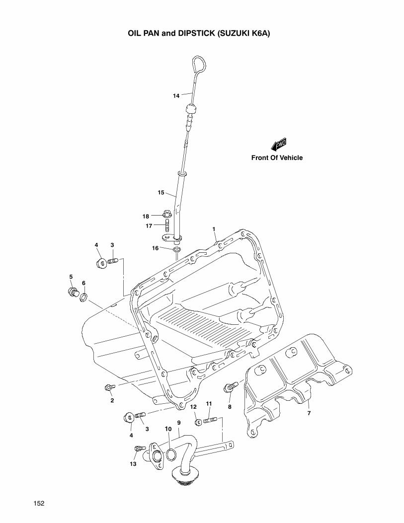
152
OIL PAN and DIPSTICK (SUZUKI K6A)
14
15
18
17
1634
65
1
2
43
13
109
1211
87
Front Of Vehicle
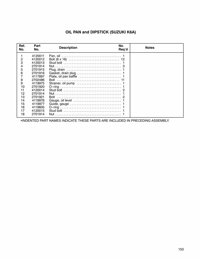
153
1 4120011 Pan, oil 1. . . . . . . . . . . . . . . . . . . . . . . . . . . . . . . . . . . .2 4120012 Bolt (6 x 16) 12. . . . . . . . . . . . . . . . . . . . . . . . . . . . . . .3 4120013 Stud bolt 1. . . . . . . . . . . . . . . . . . . . . . . . . . . . . . . . . . .4 2701914 Nut 3. . . . . . . . . . . . . . . . . . . . . . . . . . . . . . . . . . . . . . . .5 2701915 Plug, drain 1. . . . . . . . . . . . . . . . . . . . . . . . . . . . . . . . .6 2701916 Gasket, drain plug 1. . . . . . . . . . . . . . . . . . . . . . . . . . .7 4117897 Plate, oil pan baffle 1. . . . . . . . . . . . . . . . . . . . . . . . . .8 2702486 Bolt 11. . . . . . . . . . . . . . . . . . . . . . . . . . . . . . . . . . . . . .9 4119975 Strainer, oil pump 1. . . . . . . . . . . . . . . . . . . . . . . . . . .10 2701920 O--ring 1. . . . . . . . . . . . . . . . . . . . . . . . . . . . . . . . . . . . .11 4120014 Stud bolt 2. . . . . . . . . . . . . . . . . . . . . . . . . . . . . . . . . . .12 2701914 Nut 1. . . . . . . . . . . . . . . . . . . . . . . . . . . . . . . . . . . . . . . .13 2701921 Bolt 2. . . . . . . . . . . . . . . . . . . . . . . . . . . . . . . . . . . . . . .14 4119976 Gauge, oil level 1. . . . . . . . . . . . . . . . . . . . . . . . . . . . .15 4119977 Guide, gauge 1. . . . . . . . . . . . . . . . . . . . . . . . . . . . . . .16 4119605 O--ring 1. . . . . . . . . . . . . . . . . . . . . . . . . . . . . . . . . . . . .17 4120015 Stud bolt 1. . . . . . . . . . . . . . . . . . . . . . . . . . . . . . . . . . .18 2701914 Nut 1. . . . . . . . . . . . . . . . . . . . . . . . . . . . . . . . . . . . . . . .
•INDENTED PART NAMES INDICATE THESE PARTS ARE INCLUDED IN PRECEDING ASSEMBLY.
Ref.No.
PartNo.
Description NotesNo.Req’d
OIL PAN and DIPSTICK (SUZUKI K6A)
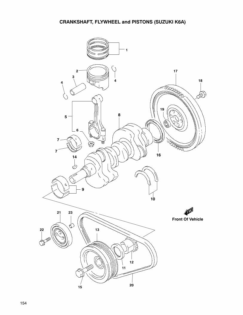
154
CRANKSHAFT, FLYWHEEL and PISTONS (SUZUKI K6A)
1
2
3
4
5
6
7
7
14
9
10
16
8
17
18
19
21
22
23
13
1520
12
11
4
Front Of Vehicle

155
1 4119978 Ring set, piston 3 Standard. . . . . . . . . . . . . . . . . . . . . . . . . . . . .4119979 Ring set, piston 3 OS:0.50. . . . . . . . . . . . . . . . . . . . . . . . . . . . .
2 4119980 Piston 3 Standard, Mark 1. . . . . . . . . . . . . . . . . . . . . . . . . . . . . . . . . . . . .4119981 Piston 3 Standard, Mark 2. . . . . . . . . . . . . . . . . . . . . . . . . . . . . . . . . . . . .4119982 Piston 3 OS:0.50. . . . . . . . . . . . . . . . . . . . . . . . . . . . . . . . . . . . .
3 4119983 Pin, piston 3. . . . . . . . . . . . . . . . . . . . . . . . . . . . . . . . . .4 4119984 Circlip 6. . . . . . . . . . . . . . . . . . . . . . . . . . . . . . . . . . . . .5 4119985 Rod, connecting 3. . . . . . . . . . . . . . . . . . . . . . . . . . . . .6 2701931 •Nut 2. . . . . . . . . . . . . . . . . . . . . . . . . . . . . . . . . . . . . . .7 4119608 Bearing set, connecting rod 6. . . . . . . . . . . . . . . . . . .8 4119986 Crankshaft 1. . . . . . . . . . . . . . . . . . . . . . . . . . . . . . . . .9 4119987 Bearing set, crankshaft 4 Green. . . . . . . . . . . . . . . . . . . . . .
4119988 Bearing set, crankshaft 4 Black. . . . . . . . . . . . . . . . . . . . . .4119989 Bearing set, crankshaft 4 Non color. . . . . . . . . . . . . . . . . . . . . .4119990 Bearing set, crankshaft 4 Yellow. . . . . . . . . . . . . . . . . . . . . .4119991 Bearing set, crankshaft 4 Brown. . . . . . . . . . . . . . . . . . . . . .
10 2701937 Bearing set, crank thrust 1 Standard. . . . . . . . . . . . . . . . . . . . .2701938 Bearing set, crank thrust 1 OS, T:2.563. . . . . . . . . . . . . . . . . . . . .
11 2701955 Seal, crankshaft front oil 1. . . . . . . . . . . . . . . . . . . . .12 4120019 Sprocket, crank timing 1. . . . . . . . . . . . . . . . . . . . . . .13 4120020 Pulley, crankshaft 1. . . . . . . . . . . . . . . . . . . . . . . . . . .14 4120021 Key 1. . . . . . . . . . . . . . . . . . . . . . . . . . . . . . . . . . . . . . .15 4120022 Bolt 1. . . . . . . . . . . . . . . . . . . . . . . . . . . . . . . . . . . . . . .16 4120023 Seal, oil 1. . . . . . . . . . . . . . . . . . . . . . . . . . . . . . . . . . . .17 4120024 Flywheel 1 Manual transmission. . . . . . . . . . . . . . . . . . . . . . . . . . . . . . . . . . .18 4119955 Bolt, 10 x 18.5 6 Manual transmission. . . . . . . . . . . . . . . . . . . . . . . . . . . . . .19 2701952 Bearing, input shaft 1 Manual transmission. . . . . . . . . . . . . . . . . . . . . . . . . .20 4120026 Water pump belt 1. . . . . . . . . . . . . . . . . . . . . . . . . . . .21 4120027 Tensioner 1. . . . . . . . . . . . . . . . . . . . . . . . . . . . . . . . . .22 4120028 Bolt 2. . . . . . . . . . . . . . . . . . . . . . . . . . . . . . . . . . . . . . .23 4120029 Pin 1. . . . . . . . . . . . . . . . . . . . . . . . . . . . . . . . . . . . . . . .
•INDENTED PART NAMES INDICATE THESE PARTS ARE INCLUDED IN PRECEDING ASSEMBLY.
Ref.No.
PartNo.
Description NotesNo.Req’d
CRANKSHAFT, FLYWHEEL and PISTONS (SUZUKI K6A)

156
11401-85893 Gasket set, complete 1. . . . .1 11141-75120 Gasket, head 1. . . . . . . . . . .2 11189-73004 Gasket, valve cover 1. . . . .3 11173-73001 Gasket, breather plate 1. . .4 11169-70D00 Gasket, distributor case 1. .
5 17431-73001 Gasket, water pump 1. . . . .6 14140-85200 Gasket, exhaust man. 1. . .
7 11229-73000 Gasket, cylndr. block plate 18 11399-73010 Gasket, timing belt cover 1.9 17569-60A10 Gasket, thermostat cap 1. .10 16119-76G00 Gasket, oil pump case 1. . .11 13119-73001-H17 Gasket, intake man. 2.
12 13125-80000-H17 Gasket, carburetor 2. .13 17559-73000-H17 Gasket, water inlet 1. .
Ref.No.
PartNo. Description
No.Req’d
No.Req’dDescription
PartNo.
Ref.No.
INDENTED PART NAMES INDICATE THESE PARTS ARE INCLUDED IN THE PRECEDING ASSEMBLY
ENGINE GASKETS (SUZUKI 970)
1
2
7
3
611
8
4
12
10
5
13
9
12 11
Front Of Vehicle

157
1 11110-80002 Head, cylinder 1. . . . . . . . . . .2 11115-82000-001 Guide, valve 8. . . . . . . .3 11112-73002 Plug, oil venturi 1. . . . . . . . .4 09241-20006 Plug 5. . . . . . . . . . . . . . . . . . .5 11141-75120 Gasket, cylinder head 1. . . .
6 04211-13189 Pin 2. . . . . . . . . . . . . . . . . . . . .7 09116-10116 Bolt (10 x 87) 10. . . . . . . . . . .8 11170-79203 Cover, cylinder head 2. . . . .9 11172-73000 Plate, breather 1. . . . . . . . . .10 11173-73001 Gasket, breather plate 1. . . .
11 02162-06103 Bolt 8. . . . . . . . . . . . . . . . . . . .12 11189-73004 Gasket, head cover 1. . . . . .
13 11180-82010 Grommet, head cover 4. . . .14 09103-06134 Bolt (6 x 65) 4. . . . . . . . . . . . .15 16920-86502 Cap, oil filler 1. . . . . . . . . . . . .16 09482-00123 Plug, spark
W16EX-U, Denso 4. . . . . . . .
or 09482-00131 Plug, sparkBP5ES, NGK 4. . . . . . . . . . . .
17 11161-79120 Case, distributor 1. . . . . . . . .18 11169-70D00 Gasket, case 1. . . . . . . . . . . .19 04221-06129 Pin 2. . . . . . . . . . . . . . . . . . . . .
20 09103-08153 Bolt, No. 2 (8 x 30) 3. . . . . . .
Ref.No.
PartNo. Description
No.Req’d
No.Req’dDescription
PartNo.
Ref.No.
INDENTED PART NAMES INDICATE THESE PARTS ARE INCLUDED IN THE PRECEDING ASSEMBLY
CYLINDER HEAD and COMPONENTS (SUZUKI 970)
20
19
17
16
4
3
15
8
7
12
13
11
9
10
6
5
14
1
218
6
Front Of Vehicle

158
1 11200-80001 Block, cylinder 1. . . . . . . . . . .2 09241-30009 Plug (OD:30) 3. . . . . . . . . . .3 09246-20006 Plug (OD:20) 2. . . . . . . . . . .4 09246-05006 Plug, oil gallery 1. . . . . . . . .5 09246-06002 Plug, oil gallery 3. . . . . . . . .
6 01550-10603 Bolt 10. . . . . . . . . . . . . . . . . .7 11219-85200 Guide, oil level gauge 1. . . .8 09103-10063 Bolt (10 x 115) 2. . . . . . . . . . .9 01421-10403 Stud bolt 1. . . . . . . . . . . . . . . .10 01421-10503 Stud bolt 1. . . . . . . . . . . . . . . .
11 08316-10103 Nut 2. . . . . . . . . . . . . . . . . . . .12 04211-13149 Pin 2. . . . . . . . . . . . . . . . . . . . .13 11221-73000 Plate, cylinder block 1. . . . . .14 11229-73000 Gasket 1. . . . . . . . . . . . . . . . .15 02162-06103 Bolt 6. . . . . . . . . . . . . . . . . . . .
16 11311-79100 Plate, clutch hsng. upper 1. .17 11320-77201 Plate, clutch hsng. lower 1. .18 16910-85550 Gauge, oil level 1. . . . . . . . . .19 37820-82001 Switch, oil pressure 1. . . . . .20 16510-82703 Filter, oil 1. . . . . . . . . . . . . . . .
21 11241-73003 Stand, oil filter 1. . . . . . . . . . .22 11510-85201 Pan, oil 1. . . . . . . . . . . . . . . . .23 09117-06059 Bolt (6 x 16) 16. . . . . . . . . . . .24 01411-06163 Stud bolt 2. . . . . . . . . . . . . . . .25 08316-10063 Nut 2. . . . . . . . . . . . . . . . . . . .
26 09247-12101 Plug, oil drain 1. . . . . . . . . . .27 09168-12018 Gasket 1. . . . . . . . . . . . . . . . .28 16520-79101 Strainer, oil pump 1. . . . . . . .29 09280-16005 O-ring 1. . . . . . . . . . . . . . . . . .30 01570-06163 Bolt 2. . . . . . . . . . . . . . . . . . . .
Ref.No.
PartNo. Description
No.Req’d
No.Req’dDescription
PartNo.
Ref.No.
INDENTED PART NAMES INDICATE THESE PARTS ARE INCLUDED IN THE PRECEDING ASSEMBLY
CYLINDER BLOCK, OIL PAN and GASKET
(SUZUKI 970)
3
18
5
4
1211
8
8
9
10
5
6
7
1
13
14
15
2
12
5
15
17
1119
21 20
16
29
2830
22
23
24 25
27
26
Front Of Vehicle

159
1 12140-75112 Ring, piston (standard) 4. . .
12140-75112-025 Ring, piston 4. . . . . . . . .
12140-75112-050 Ring, piston 4. . . . . . . . .
2 12111-85201-0B0 Piston (standard) 4. . . .
12111-85201-025 Piston (OS:0.25) 4. . . . .
12111-85201-050 Piston (OS:0.50) 4. . . . .
3 12151-29001 Pin, piston 4. . . . . . . . . . . . . .
4 09381-16001 Circlip 8. . . . . . . . . . . . . . . . . .
5 12160-73010 Rod, connecting 4. . . . . . . . .
6 09159-08033 Nut, connecting rod 8. . . . .
7 12181-81051-0A0 Bearing (standard) 8. . .
12181-81051-025 Bearing, cnctng. rod 8. .
12181-81051-050 Bearing, cnctng. rod 8. .
12181-81051-075 Bearing, cnctng. rod 8. .
12181-81051-100 Bearing, cnctng. rod 8. .
8 12221-75104 Crankshaft 1. . . . . . . . . . . . . .
9 12300-73812-0A0 Bearing set, crnkshft. 1.
12300-73812-025 Bearing set, crnkshft. 1.
12300-73812-050 Bearing set, crnkshft. 1.
12300-73812-075 Bearing set, crnkshft. 1.12300-73812-100 Bearing set, crnkshft. 1.
10 12300-73830 Bearing set, crank thrust 1. .12300-73830-012 Bearing set, thrust 1. . .12300-73830-025 Bearing set, thrust 1. . .
11 09283-32040 Seal, front 1. . . . . . . . . . . . . .12 12635-78401 Guide, timing belt 1. . . . . . . .13 12631-78401 Pulley, timing belt 1. . . . . . . .14 08341-31059 Key 1. . . . . . . . . . . . . . . . . . . .15 12611-66C00 Pulley, crank 1. . . . . . . . . . . .
16 12619-60B00 Bolt 1. . . . . . . . . . . . . . . . . . . .17 09283-60005 Seal, rear main 1. . . . . . . . . .18 11341-70B01 Housing, oil seal 1. . . . . . . . .19 01550-06203 Bolt 4. . . . . . . . . . . . . . . . . . . .20 02122-06253 Bolt 2. . . . . . . . . . . . . . . . . . . .21 04211-09109 Pin 2. . . . . . . . . . . . . . . . . . . . .
22 12620-85301 Flywheel 1. . . . . . . . . . . . . . . .23 09103-10097 Bolt (10 x 17) 6. . . . . . . . . . . .24 04421-06129 Pin 1. . . . . . . . . . . . . . . . . . . . .25 12623-70B00 Bearing, input shaft 1. . . . . .
Ref.No.
PartNo. Description
No.Req’d
No.Req’dDescription
PartNo.
Ref.No.
INDENTED PART NAMES INDICATE THESE PARTS ARE INCLUDED IN THE PRECEDING ASSEMBLY
CRANKSHAFT, FLYWHEEL and PISTONS (SUZUKI 970)
1
4
4
3
2
5
6
7
9
14
8
10
1513
12
11
18
22
21
23
19
16
17
20
24
25
(1)
(1)
(2)
(2)
(7)
(7)
(7)
(7)
(9)
(9)
(9)(9)
(10)(10)
Front Of Vehicle
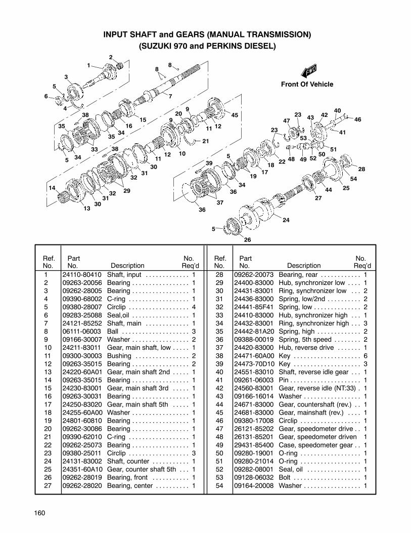
160
1 24110-80410 Shaft, input 1. . . . . . . . . . . . .2 09263-20056 Bearing 1. . . . . . . . . . . . . . . . .3 09262-28005 Bearing 1. . . . . . . . . . . . . . . . .4 09390-68002 C-ring 1. . . . . . . . . . . . . . . . . .5 09380-28007 Circlip 4. . . . . . . . . . . . . . . . . .
6 09283-25088 Seal,oil 1. . . . . . . . . . . . . . . . .7 24121-85252 Shaft, main 1. . . . . . . . . . . . .8 06111-06003 Ball 3. . . . . . . . . . . . . . . . . . . .9 09166-30007 Washer 2. . . . . . . . . . . . . . . . .10 24211-83011 Gear, main shaft, low 1. . . . .
11 09300-30003 Bushing 2. . . . . . . . . . . . . . . .12 09263-35015 Bearing 2. . . . . . . . . . . . . . . . .13 24220-60A01 Gear, main shaft 2nd 1. . . . .14 09263-35015 Bearing 1. . . . . . . . . . . . . . . . .15 24230-83001 Gear, main shaft 3rd 1. . . . .16 09263-30031 Bearing 1. . . . . . . . . . . . . . . . .
17 24250-83020 Gear, main shaft 5th 1. . . . .18 24255-60A00 Washer 1. . . . . . . . . . . . . . . . .19 24801-60810 Bearing 1. . . . . . . . . . . . . . . . .20 09262-30086 Bearing 1. . . . . . . . . . . . . . . . .21 09390-62010 C-ring 1. . . . . . . . . . . . . . . . . .
22 09262-25073 Bearing 1. . . . . . . . . . . . . . . . .23 09380-25011 Circlip 3. . . . . . . . . . . . . . . . . .24 24131-83002 Shaft, counter 1. . . . . . . . . . .25 24351-60A10 Gear, counter shaft 5th 1. . .26 09262-28019 Bearing, front 1. . . . . . . . . . .
27 09262-28020 Bearing, center 1. . . . . . . . . .
28 09262-20073 Bearing, rear 1. . . . . . . . . . . .29 24400-83000 Hub, synchronizer low 1. . . .30 24431-83001 Ring, synchronizer low 2. . .31 24436-83000 Spring, low/2nd 2. . . . . . . . . .32 24441-85F41 Spring, low 2. . . . . . . . . . . . . .
33 24410-83000 Hub, synchronizer high 1. . .34 24432-83001 Ring, synchronizer high 3. . .35 24442-81A20 Spring, high 2. . . . . . . . . . . . .36 09388-00019 Spring, 5th speed 2. . . . . . . .37 24420-83000 Hub, reverse drive 1. . . . . . .
38 24471-60A00 Key 6. . . . . . . . . . . . . . . . . . . .39 24473-70D10 Key 3. . . . . . . . . . . . . . . . . . . .40 24551-83010 Shaft, reverse idle gear 1. . .41 09261-06003 Pin 1. . . . . . . . . . . . . . . . . . . . .42 24560-83001 Gear, reverse idle (NT:33) 1.43 09166-16014 Washer 1. . . . . . . . . . . . . . . . .
44 24671-83000 Gear, countershaft (rev.) 1. .45 24681-83000 Gear, mainshaft (rev.) 1. . . .46 09380-17008 Circlip 1. . . . . . . . . . . . . . . . . .47 26121-85202 Gear, speedometer drive 1. .48 26131-85201 Gear, speedometer driven 1
49 29431-85400 Case, speedometer gear 1. .50 09280-19001 O-ring 1. . . . . . . . . . . . . . . . . .51 09280-21014 O-ring 1. . . . . . . . . . . . . . . . . .52 09282-08001 Seal, oil 1. . . . . . . . . . . . . . . .53 09128-06032 Bolt 1. . . . . . . . . . . . . . . . . . . .
54 09164-20008 Washer 1. . . . . . . . . . . . . . . . .
Ref.No.
PartNo. Description
No.Req’d
No.Req’dDescription
PartNo.
Ref.No.
INPUT SHAFT and GEARS (MANUAL TRANSMISSION)
(SUZUKI 970 and PERKINS DIESEL)
11
13
12
9
8
36
10
37
39
38
19
23
14
7
16
5
4
2
3
1
6
30
29
17
22
21
18
20
3534
33
3132
1535
345
38
3231
30
11
9
12
45
3634
5
2347
48 4950
51
52
53
43 4240
46
41
28
54
2544
27
24
26
5
8
Front Of Vehicle

161
1 24700-85200 Case, transmission 1. . . . . . .2 04211-13149 Pin 2. . . . . . . . . . . . . . . . . . . .3 09103-08131 Bolt, No. 1 (8 x 120) 4. . . . .4 01550-08303 Bolt, No. 2 3. . . . . . . . . . . . .5 01550-08403 Bolt, No. 3 1. . . . . . . . . . . . .
6 01550-08803 Bolt, No. 4 2. . . . . . . . . . . . .7 24741-83001 Retainer, input shaft brng. 1.8 09103-08152 Bolt (8 x 25) 8. . . . . . . . . . . . .9 09250-30003 Cap, inspection timing 1. . . .10 37610-80023 Switch, back-up lamp 1. . . . .
11 09280-11002 O-ring 1. . . . . . . . . . . . . . . . .
12 09250-10006 Plug, locating 1. . . . . . . . . . . .13 24770-85252 Case, extension 1. . . . . . . . .14 04211-13149 Pin 2. . . . . . . . . . . . . . . . . . . . .15 09103-08132 Bolt, No. 1 (8 x 100) 3. . . . . .16 01550-08403 Bolt, No. 2 1. . . . . . . . . . . . . .
17 01550-08353 Bolt, No. 3 5. . . . . . . . . . . . . .18 01421-08303 Stud bolt 1. . . . . . . . . . . . . . . .19 08316-10083 Nut 1. . . . . . . . . . . . . . . . . . . .20 24780-83010 Seal, extension case 1. . . . .21 09246-16010 Plug, oil filler 2. . . . . . . . . . . .
Ref.No.
PartNo. Description
No.Req’d
No.Req’dDescription
PartNo.
Ref.No.
14
• INDENTED PART NAMES INDICATE THESE PARTS ARE INCLUDED IN THE PRECEDING ASSEMBLY
53
4 6
3
3
443
6
10
11
18 19
20
16
17
21
15
13
12
2
9
1
8
7
TRANSMISSION CASE
(SUZUKI 970 and PERKINS DIESEL)
Front Of Vehicle
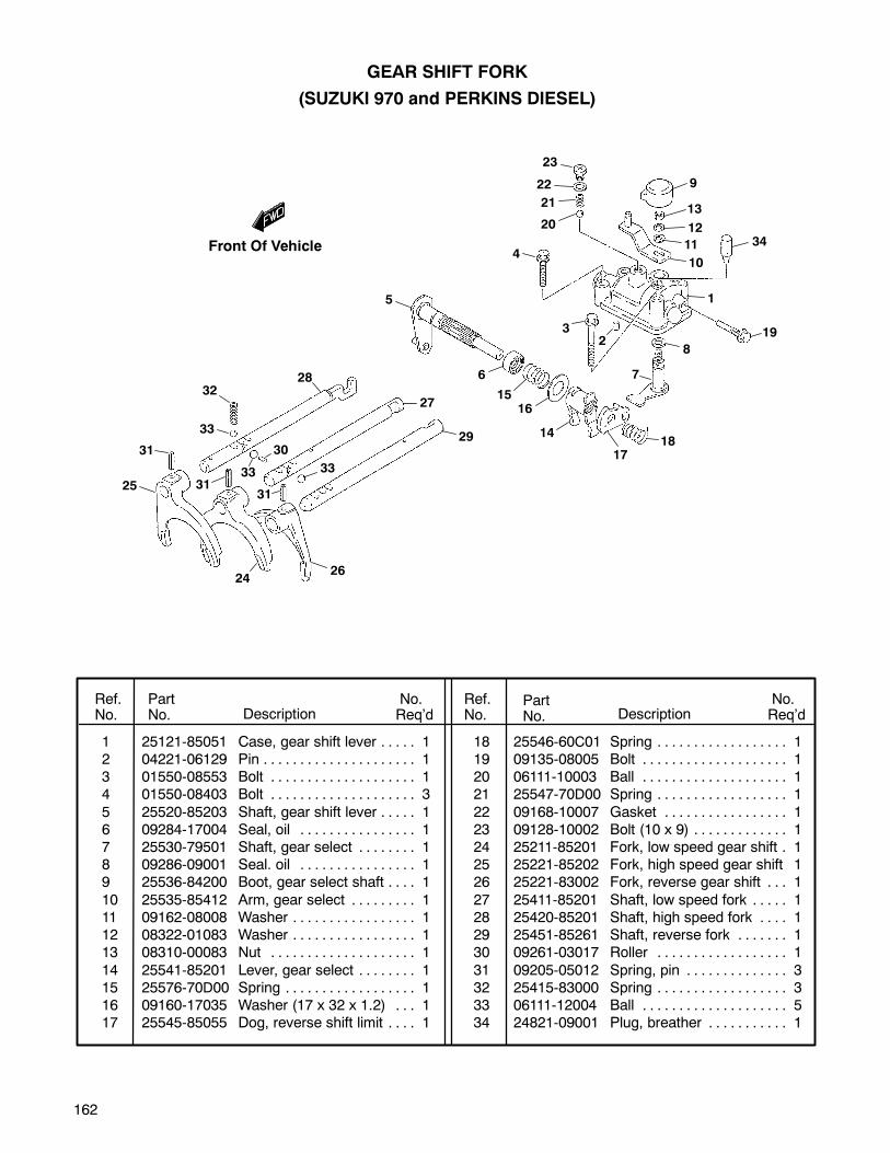
162
GEAR SHIFT FORK
(SUZUKI 970 and PERKINS DIESEL)
1 25121-85051 Case, gear shift lever 1. . . . .2 04221-06129 Pin 1. . . . . . . . . . . . . . . . . . . . .3 01550-08553 Bolt 1. . . . . . . . . . . . . . . . . . . .4 01550-08403 Bolt 3. . . . . . . . . . . . . . . . . . . .
5 25520-85203 Shaft, gear shift lever 1. . . . .6 09284-17004 Seal, oil 1. . . . . . . . . . . . . . . .7 25530-79501 Shaft, gear select 1. . . . . . . .8 09286-09001 Seal. oil 1. . . . . . . . . . . . . . . .9 25536-84200 Boot, gear select shaft 1. . . .
10 25535-85412 Arm, gear select 1. . . . . . . . .11 09162-08008 Washer 1. . . . . . . . . . . . . . . . .12 08322-01083 Washer 1. . . . . . . . . . . . . . . . .13 08310-00083 Nut 1. . . . . . . . . . . . . . . . . . . .
14 25541-85201 Lever, gear select 1. . . . . . . .15 25576-70D00 Spring 1. . . . . . . . . . . . . . . . . .16 09160-17035 Washer (17 x 32 x 1.2) 1. . .17 25545-85055 Dog, reverse shift limit 1. . . .
18 25546-60C01 Spring 1. . . . . . . . . . . . . . . . . .19 09135-08005 Bolt 1. . . . . . . . . . . . . . . . . . . .20 06111-10003 Ball 1. . . . . . . . . . . . . . . . . . . .21 25547-70D00 Spring 1. . . . . . . . . . . . . . . . . .
22 09168-10007 Gasket 1. . . . . . . . . . . . . . . . .23 09128-10002 Bolt (10 x 9) 1. . . . . . . . . . . . .24 25211-85201 Fork, low speed gear shift 1.25 25221-85202 Fork, high speed gear shift 126 25221-83002 Fork, reverse gear shift 1. . .
27 25411-85201 Shaft, low speed fork 1. . . . .28 25420-85201 Shaft, high speed fork 1. . . .29 25451-85261 Shaft, reverse fork 1. . . . . . .30 09261-03017 Roller 1. . . . . . . . . . . . . . . . . .
31 09205-05012 Spring, pin 3. . . . . . . . . . . . . .32 25415-83000 Spring 3. . . . . . . . . . . . . . . . . .33 06111-12004 Ball 5. . . . . . . . . . . . . . . . . . . .34 24821-09001 Plug, breather 1. . . . . . . . . . .
Ref.No.
PartNo. Description
No.Req’d
No.Req’dDescription
PartNo.
Ref.No.
22
23
21
20
9
13
12
11
10
34
19
4
1
23
8
7
1817
14
1615
6
5
28
27
29
32
33
31
25
2426
33
3131
33
30
Front Of Vehicle

163
STARTER MOTOR (SUZUKI 970)
Ref.No.
PartNo. Description
No.Req’d
No.Req’dDescription
PartNo.
Ref.No.
9
1 31100-79X50 Motor, starting 1. . . . . . . . . . .2 31152-51A10 Bushing 1. . . . . . . . . . . . . . .3 31220-51A10 Switch assembly 1. . . . . . . .4 08316-10063 Nut 2. . . . . . . . . . . . . . . . . . . .
5 31191-85020 Lever, pinion drive 1. . . . . . .6 08316-10083 Nut, switch 2. . . . . . . . . . . . .7 31153-51A10 Washer 1. . . . . . . . . . . . . . . .8 31312-51A10 Ring, snap 1. . . . . . . . . . . . .9 31310-51A10 Nut, pinion stop 2. . . . . . . . .
10 31320-51A10 Clutch assembly 1. . . . . . . .
11 31311-51A10 Armature 1. . . . . . . . . . . . . .12 31110-52A50 Yoke assembly 1. . . . . . . . .13 31131-51A10 Brush 4. . . . . . . . . . . . . . . . .14 31135-51A10 Spring, brush 4. . . . . . . . . . .
15 31173-51A10 Holder, brush 1. . . . . . . . . . .16 31175-51A10 Insulator 1. . . . . . . . . . . . . . .17 31172-51A10 Bushing 1. . . . . . . . . . . . . . .18 31281-51A10 Bolt 2. . . . . . . . . . . . . . . . . . .19 08316-10083 Nut 1. . . . . . . . . . . . . . . . . . . .
INDENTED PART NAMES INDICATE THESE PARTS ARE INCLUDED IN THE PRECEDING ASSEMBLY
728
45
3
19
6
11
10
14
12
1516
1718
13
14
1
Front Of Vehicle
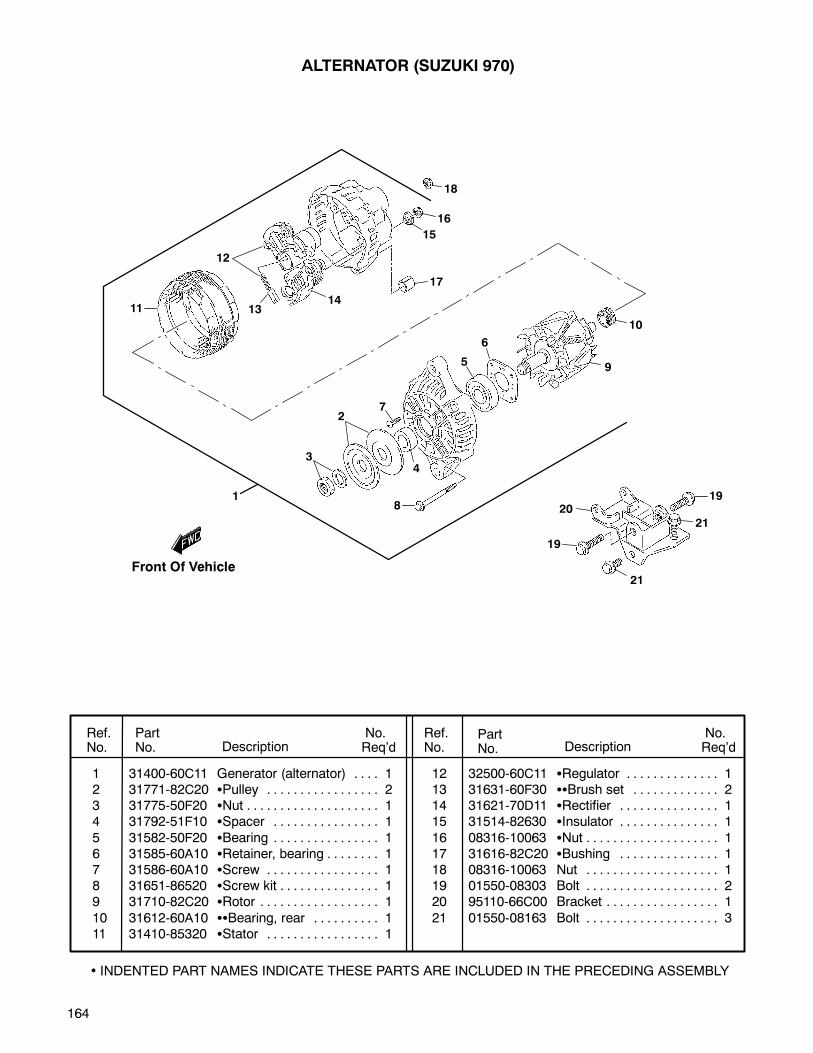
164
ALTERNATOR (SUZUKI 970)
Ref.No.
PartNo. Description
No.Req’d
No.Req’dDescription
PartNo.
Ref.No.
• INDENTED PART NAMES INDICATE THESE PARTS ARE INCLUDED IN THE PRECEDING ASSEMBLY
1 31400-60C11 Generator (alternator) 1. . . .2 31771-82C20 Pulley 2. . . . . . . . . . . . . . . . .3 31775-50F20 Nut 1. . . . . . . . . . . . . . . . . . . .4 31792-51F10 Spacer 1. . . . . . . . . . . . . . . .
5 31582-50F20 Bearing 1. . . . . . . . . . . . . . . .6 31585-60A10 Retainer, bearing 1. . . . . . . .7 31586-60A10 Screw 1. . . . . . . . . . . . . . . . .8 31651-86520 Screw kit 1. . . . . . . . . . . . . . .9 31710-82C20 Rotor 1. . . . . . . . . . . . . . . . . .
10 31612-60A10 Bearing, rear 1. . . . . . . . . .11 31410-85320 Stator 1. . . . . . . . . . . . . . . . .
12 32500-60C11 Regulator 1. . . . . . . . . . . . . .13 31631-60F30 Brush set 2. . . . . . . . . . . . .14 31621-70D11 Rectifier 1. . . . . . . . . . . . . . .15 31514-82630 Insulator 1. . . . . . . . . . . . . . .
16 08316-10063 Nut 1. . . . . . . . . . . . . . . . . . . .17 31616-82C20 Bushing 1. . . . . . . . . . . . . . .18 08316-10063 Nut 1. . . . . . . . . . . . . . . . . . . .19 01550-08303 Bolt 2. . . . . . . . . . . . . . . . . . . .20 95110-66C00 Bracket 1. . . . . . . . . . . . . . . . .
21 01550-08163 Bolt 3. . . . . . . . . . . . . . . . . . . .
10
11
12
1314
17
15
16
18
9
6
5
72
3
8
19
21
2019
21
4
1
Front Of Vehicle
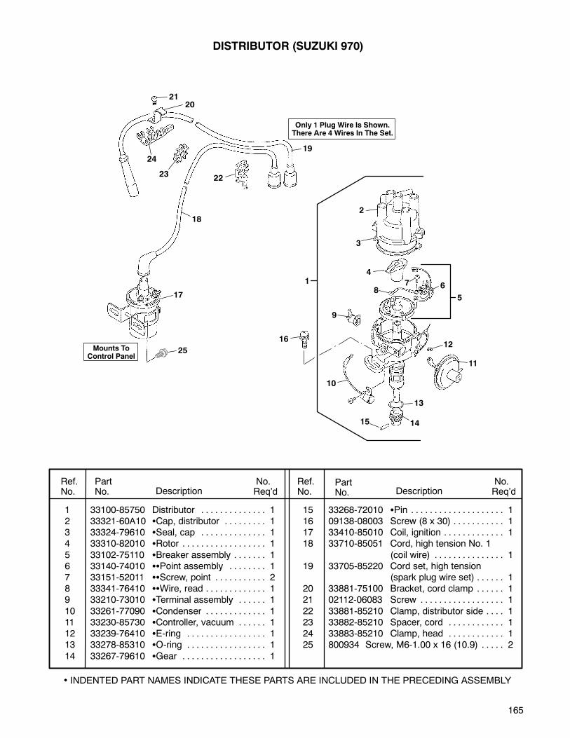
165
DISTRIBUTOR (SUZUKI 970)
Ref.No.
PartNo. Description
No.Req’d
No.Req’dDescription
PartNo.
Ref.No.
• INDENTED PART NAMES INDICATE THESE PARTS ARE INCLUDED IN THE PRECEDING ASSEMBLY
1 33100-85750 Distributor 1. . . . . . . . . . . . . .2 33321-60A10 Cap, distributor 1. . . . . . . . .3 33324-79610 Seal, cap 1. . . . . . . . . . . . . .4 33310-82010 Rotor 1. . . . . . . . . . . . . . . . . .
5 33102-75110 Breaker assembly 1. . . . . . .6 33140-74010 Point assembly 1. . . . . . . .7 33151-52011 Screw, point 2. . . . . . . . . . .8 33341-76410 Wire, read 1. . . . . . . . . . . . .9 33210-73010 Terminal assembly 1. . . . . .
10 33261-77090 Condenser 1. . . . . . . . . . . . .11 33230-85730 Controller, vacuum 1. . . . . .12 33239-76410 E-ring 1. . . . . . . . . . . . . . . . .13 33278-85310 O-ring 1. . . . . . . . . . . . . . . . .
14 33267-79610 Gear 1. . . . . . . . . . . . . . . . . .
15 33268-72010 Pin 1. . . . . . . . . . . . . . . . . . . .16 09138-08003 Screw (8 x 30) 1. . . . . . . . . . .17 33410-85010 Coil, ignition 1. . . . . . . . . . . . .18 33710-85051 Cord, high tension No. 1
(coil wire) 1. . . . . . . . . . . . . . .19 33705-85220 Cord set, high tension
(spark plug wire set) 1. . . . . .20 33881-75100 Bracket, cord clamp 1. . . . . .21 02112-06083 Screw 1. . . . . . . . . . . . . . . . . .
22 33881-85210 Clamp, distributor side 1. . . .23 33882-85210 Spacer, cord 1. . . . . . . . . . . .24 33883-85210 Clamp, head 1. . . . . . . . . . . .25 800934 Screw, M6-1.00 x 16 (10.9) 2. . . . .
1
2120
24
2322
17
25
19
2
3
4
87 6
5
9
10
15 14
13
11
12
18
16
Only 1 Plug Wire Is Shown.There Are 4 Wires In The Set.
Mounts ToControl Panel

166
MECHANICAL PTO
(SUZUKI 970 and PERKINS DIESEL)
The parts breakdown illustration was notavailable at the time of this printing.
The isometric view of the transmission shownat the right references the location of the PTOhousing. Please use the illustrations shownbelow for individual PTO parts.
Transmission fluid capacity is 2.6 pints(80W-90 gear oil). Fill to bottom of threads ofoil fill plug hole, located on right side of PTOhousing.
26
20
1
3
22
3031
28
132
7
23
33
21
19
25 24
6
125
Some of the parts shownabove are also referenced inthe illustrations shown below.
10
27
27
29
34
35
32
In reference to items 30, 31 & 32,make sure oil holes in gear alignwith oil holes in the bushings.
OilHoles
OilHoles
Bushings
38
38
84
927
11
20
1
3
10
16
1718
9
15
14
99
9
9
9
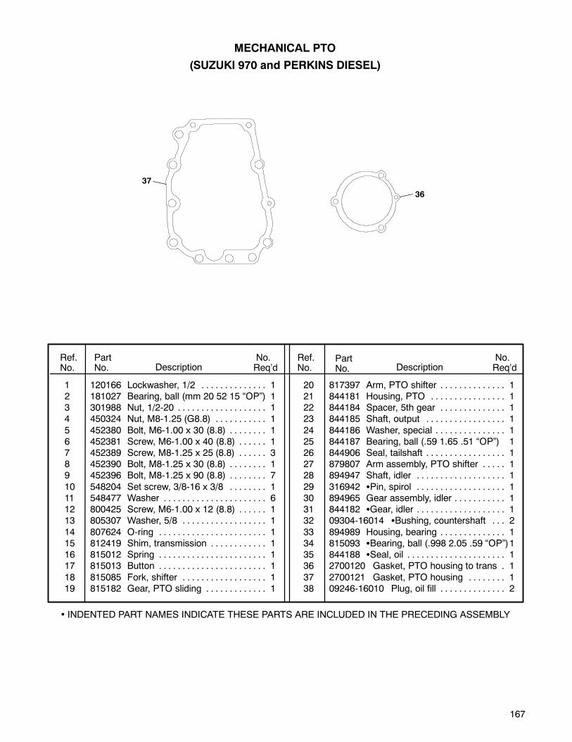
167
1 120166 Lockwasher, 1/2 1. . . . . . . . . . . . . .2 181027 Bearing, ball (mm 20 52 15 “OP”) 13 301988 Nut, 1/2-20 1. . . . . . . . . . . . . . . . . . .4 450324 Nut, M8-1.25 (G8.8) 1. . . . . . . . . . .
5 452380 Bolt, M6-1.00 x 30 (8.8) 1. . . . . . . .6 452381 Screw, M6-1.00 x 40 (8.8) 1. . . . . .7 452389 Screw, M8-1.25 x 25 (8.8) 3. . . . . .8 452390 Bolt, M8-1.25 x 30 (8.8) 1. . . . . . . .9 452396 Bolt, M8-1.25 x 90 (8.8) 7. . . . . . . .
10 548204 Set screw, 3/8-16 x 3/8 1. . . . . . . .11 548477 Washer 6. . . . . . . . . . . . . . . . . . . . . .12 800425 Screw, M6-1.00 x 12 (8.8) 1. . . . . .13 805307 Washer, 5/8 1. . . . . . . . . . . . . . . . . .
14 807624 O-ring 1. . . . . . . . . . . . . . . . . . . . . . .15 812419 Shim, transmission 1. . . . . . . . . . . .16 815012 Spring 1. . . . . . . . . . . . . . . . . . . . . . .17 815013 Button 1. . . . . . . . . . . . . . . . . . . . . . .
18 815085 Fork, shifter 1. . . . . . . . . . . . . . . . . .19 815182 Gear, PTO sliding 1. . . . . . . . . . . . .
20 817397 Arm, PTO shifter 1. . . . . . . . . . . . . .21 844181 Housing, PTO 1. . . . . . . . . . . . . . . .22 844184 Spacer, 5th gear 1. . . . . . . . . . . . . .23 844185 Shaft, output 1. . . . . . . . . . . . . . . . .
24 844186 Washer, special 1. . . . . . . . . . . . . . .25 844187 Bearing, ball (.59 1.65 .51 “OP”) 126 844906 Seal, tailshaft 1. . . . . . . . . . . . . . . . .27 879807 Arm assembly, PTO shifter 1. . . . .28 894947 Shaft, idler 1. . . . . . . . . . . . . . . . . . .
29 316942 Pin, spirol 1. . . . . . . . . . . . . . . . . . .30 894965 Gear assembly, idler 1. . . . . . . . . . .31 844182 Gear, idler 1. . . . . . . . . . . . . . . . . . .32 09304-16014 Bushing, countershaft 2. . .
33 894989 Housing, bearing 1. . . . . . . . . . . . . .34 815093 Bearing, ball (.998 2.05 .59 “OP”)135 844188 Seal, oil 1. . . . . . . . . . . . . . . . . . . . .36 2700120 Gasket, PTO housing to trans 1.
37 2700121 Gasket, PTO housing 1. . . . . . . .38 09246-16010 Plug, oil fill 2. . . . . . . . . . . . . .
Ref.No.
PartNo. Description
No.Req’d
No.Req’dDescription
PartNo.
Ref.No.
MECHANICAL PTO
(SUZUKI 970 and PERKINS DIESEL)
• INDENTED PART NAMES INDICATE THESE PARTS ARE INCLUDED IN THE PRECEDING ASSEMBLY
37
36
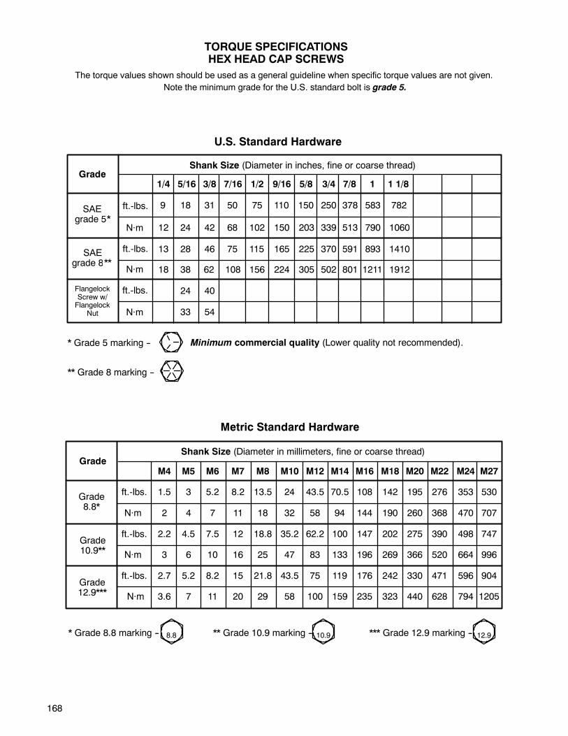
168
M4 M5 M6 M7 M8 M10 M12 M14 M16 M18 M20 M22 M24 M27
ft.-lbs. 1.5 3 5.2 8.2 13.5 24 43.5 70.5 108 142 195 276 353 530
N·m 2 4 7 11 18 32 58 94 144 190 260 368 470 707
ft.-lbs. 2.2 4.5 7.5 12 18.8 35.2 62.2 100 147 202 275 390 498 747
N·m 3 6 10 16 25 47 83 133 196 269 366 520 664 996
ft.-lbs. 2.7 5.2 8.2 15 21.8 43.5 75 119 176 242 330 471 596 904
N·m 3.6 7 11 20 29 58 100 159 235 323 440 628 794 1205
TORQUE SPECIFICATIONSHEX HEAD CAP SCREWS
* Grade 5 marking --
U.S. Standard Hardware
The torque values shown should be used as a general guideline when specific torque values are not given.
** Grade 8 marking --
GradeShank Size (Diameter in millimeters, fine or coarse thread)
Grade8.8*
Grade10.9**
Grade12.9***
Metric Standard Hardware
* Grade 8.8 marking -- ** Grade 10.9 marking -- *** Grade 12.9 marking --8.8 10.9 12.9
SAEgrade 8 **
GradeShank Size (Diameter in inches, fine or coarse thread)
SAEgrade 5 *
FlangelockScrew w/Flangelock
Nut
1/4 5/16 3/8 7/16 1/2 9/16 5/8 3/4 7/8 1 1 1/8
18 38 62 108 156 224 305 502 801 1211 1912
9 18 31 50 75 110 150 250 378 583 782
12 24 42 68 102 150 203 339 513 790 1060
13 28 46 75 115 165 225 370 591 893 1410
24 40
33 54
ft.-lbs.
N·m
ft.-lbs.
ft.-lbs.
N·m
N·m
*
**
Minimum commercial quality (Lower quality not recommended).
Note the minimum grade for the U.S. standard bolt is grade 5.
169
SERVICE
DATE SERVICE DONE INITIAL
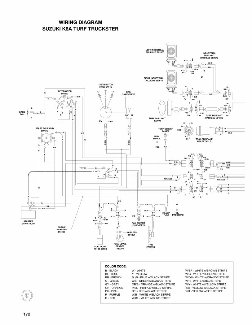
170
G
R
RB
B
OR
W/Y
P/BLW/BR
W/R
W/B
R/B
G
B
W
G
OR
OR
W/B Y
YB
BR
BL/B
R/B
B
W
R
B
W/R
B
B/W BR
BR/B W/BR
B/W
GB
B
R10 GAUGE
W/BOR
ORBB
B
R/B
R
B
R
W
BL
B
OR/B
BR
R R
BR
B
OR
BL/B
B
BR
R/B
BRBR
B
BL/B
BR
BB
R/B
BR
BL/B
R/B
B
B 10 GAUGE
R
B
B
W/R
W/BR
P/BL
W/Y
W/BR/B
R
P/BL
P
B
G
P
W
W/Y
BB
B
W/R
BS
EXC P
W/R
B
BG
G
B
R
R
RR
R
R
R
OILPRESSURE
W
BRB/W
W/BR
G
G
G
G
OR
B
B
B
B
BB
PB
Y
OR
OR
W/Y
W/Y
R
B
R
BBL/B
R/B
BB
RP
G
W
B
B
P/BL
P/BL
B
R
W/B
R
-+
R/B
G
20 AMPFUSE
R
P
R
W/R
R/B
R
B
B
B
B
BR
BR
OR/BBR
BBL
R
W/R
B
W/BR
B
B
W/R
W/BR
LEFT INDUSTRIALTAILLIGHT 892676 INDUSTRIAL
TAILLIGHTHARNESS 892676
RIGHT INDUSTRIALTAILLIGHT 892676
TURF TAILLIGHTHARNESS 894313
TRAILER BRAKERECEPTACLE
FAN2700799
FAN SWITCH17680-50F70
HARNESS894201
FUEL LEVELSENDER843298
FUEL PUMP15100-53F03
ENGINEHARNESS894189
STARTER31100-70D50
PARKBRAKE
TEMP SENDER843857
COIL33410-50F20
DISTRIBUTOR33100-51F10
TURF TAILLIGHT893602
ALTERNATOR893633
START SOLENOID889673
CARBSOL
WIRING DIAGRAM
SUZUKI K6A TURF TRUCKSTER
COLOR CODE:
B - BLACK W - WHITE W/BR - WHITE w/BROWN STRIPE
BL - BLUE Y - YELLOW W/G - WHITE w/GREEN STRIPE
BR - BROWN BL/B - BLUE w/BLACK STRIPE W/OR - WHITE w/ORANGE STRIPE
G - GREEN G/B - GREEN w/BLACK STRIPE W/R - WHITE w/RED STRIPE
GY - GREY OR/B - ORANGE w/BLACK STRIPE W/Y - WHITE w/YELLOW STRIPE
OR - ORANGE P/BL - PURPLE w/BLUE STRIPE Y/B - YELLOW w/BLACK STRIPE
PK - PINK R/B - RED w/BLACK STRIPE Y/R - YELLOW w/RED STRIPE
P - PURPLE W/B - WHITE w/BLACK STRIPE
R - RED W/BL - WHITE w/BLUE STRIPE
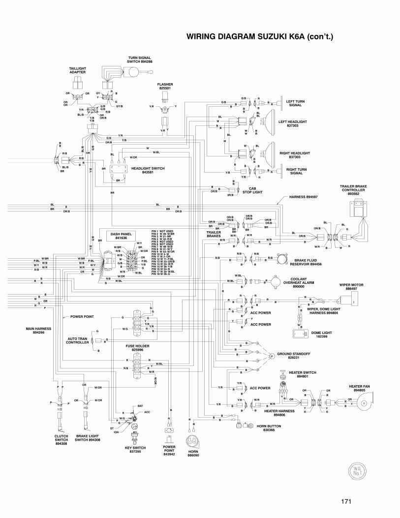
171
W/G
HEATER HARNESS894806
Y
R/B
R R
B
W/R
BR
Y
R
Y
B
OR OR
B
OR
OROR
OR
R/B
B
BB
0R/B
R
B
Y/R
B
Y/R
B
Y/B
B
G/B
B
Y
B
W/BL
B
R/B
Y/R Y
ST
IGN
BAT
ACC
W/R B
OR/B
BLBL
WR
G
BLW
BB
BLBL
WW
BB
R
R
BB
BB
B
OR/BOR/B
BB
W/R
RB
G
GY/B
Y
GY
Y/R
BL/BY/BY/B
OROR/B
OR/BOR/B
BRBR
BR
OR
P/BL
W/Y
BR
Y/BB
W/BL
R/B
W/BR
W
G/B
G
W/R
W/B
W/OR
G/BG/B
R/B
BL/B
BR
BB
R/B
B
G
ORP
W/OR
P
WB
B
RB
RRB
RB
R OR
CRML
ORR
YB
W/RB
B
Y/R
BR/B
B
BB
B
B
B
B
BB
R
OR/B
R
Y/R
Y/R
B
B
Y/R
W
B
B
R
R
BR
BL
BL
RB
BL
BB
B
G/B
G/B
Y/R
BR
B
BR
R/B
B
BL/B
B
Y/R
B
W/BL
B
B
B
G
B
W/OR
Y
R
R
RR
R
Y
B
W/OR
W/OR
OR
G
B
W/RB
BB
R
G
G
G
ORW
R/B
PIN 1 NOT USEDPIN 2 W 49-W/BRPIN 3 W 21- BRPIN 4 W 42- R/BPIN 5 NOT USEDPIN 6 NOT USEDPIN 7 W 48-W/BPIN 8 W 31-W/YPIN 9 W 53-W/ORPIN 10 W 4-WPIN 11 W 2- ORPIN 12 W 11- P/BLPIN 13 W 33- GR/BPIN 14 W 34-W/RPIN 15 W 36- Y/BPIN 16 W 54- BPIN 17 W 30-W/BLPIN 18 W 28- G
W/BR
W/RW/Y
W/BP/BL
BR
BR
B
G/B
W/R
P
G
P
OR/BOR/B
OR/B
Y/B
Y/B
Y/B
G/B
OR
Y/B
OR/B
B
B
B
BL
BL
W
W
W/OR
Y
W/BL
BR
B
BR
B
B
W/G
Y
P
W/R
B
B
B
R
R
W/BL
B
R/B
G
W/BL
OR/B
OR/BOR/B
BR
TAILLIGHTADAPTER
TURN SIGNALSWITCH 894288
FLASHER825501
LEFT TURNSIGNAL
LEFT HEADLIGHT837303
RIGHT HEADLIGHT837303
RIGHT TURNSIGNAL
CABSTOP LIGHT
HEADLIGHT SWITCH843581
BLB
OR/BBR
TRAILERBRAKES W/R
BRAKE FLUIDRESERVOIR 894456
COOLANTOVERHEAT ALARM
890000
DASH PANEL841636
POWER POINT
R/B
WOR
G
PR
R
BB
BB
W/R
W/BW/Y
P/BLW/BR
MAIN HARNESS894266
AUTO TRANCONTROLLER
ACC POWER
ACC POWER
WIPER MOTOR886497
WIPER, DOME LIGHTHARNESS 894804
DOME LIGHT182399
HEATER FAN894805
HEATER SWITCH894801
GROUND STANDOFF828231
HORN BUTTON830366
ACC POWER
HORN886090
POWERPOINT843942
KEY SWITCH837295
BRAKE LIGHTSWITCH 894308
CLUTCHSWITCH894308
TRAILER BRAKECONTROLLER
893562HARNESS 894597
FUSE HOLDER825996
WIRING DIAGRAM SUZUKI K6A (con’t.)

172
G
G
Y
PK
ORG
R
WIRING DIAGRAM
SUZUKI K6A TURF TRUCKSTER with
AUTOMATIC TRANSMISSION (con’t.)
W/BR
B/W
GB
B
B
R
W/BR G
W/BRG
B
Y
R/B
PK
W/G
B
B
R
P/BL
PKPK
W/Y
W
W/R
OR
B
BR/B
R
Y
YR
W/B
B
W/G
W/G
PIN 1 WHITE/BLUEPIN 2 BROWNPIN 3 PINKPIN 4 YELLOWPIN 5 GREENPIN 6 WHITE/GREENPIN 7 WHITE/YELLOWPIN 8 GRAYPIN 9 ORANGEPIN 10 BLUEPIN 11 NOT USEDPIN 12 NOT USEDPIN 13 NOT USEDPIN 14 NOT USEDPIN 15 NOT USEDPIN 16 SHIELD (CABLE)PIN 17 BLACK (CABLE)PIN 18 CLEAR (CABLE)
G
W/BR
G
CLEAR
B
W/BR
R
R
Y
R
W
R
W
R
B
B
BR
B
OR
W/OR PKPK
W/BR
B
BB
OR
OR
RR
R
W/R
S
B
R
R
GG
W/BR
CLEAR
B
BLW/Y
W/BL
GYBL
G
B
BLBL BR
B BL
GW/G
W/BRBR
GB
W/BR
GG
W/R GG
W/R
BW/G
R
GOR G
Y
B
W
W
B
R
B
BRBR
G
B
PK
B
W/R
OR
R
BB
OR
B
B
SHIELD
BR
G
B
B
W/BLGY
W/YY
G
W/BL
W/Y
GY
W/G
W/G
BL
BL
W/BR
R
G
G
BRB/W
G
W/BR
BL
W/OR
PK
PK
G
G
B
B
B
B
B
B
G
R
W/BRGG
OR
OR
B
W/Y
R
W/Y
PK
W/BR
BP/BL
P/BL
B
BL
PEXC
R/B
R
-+ R/B
W/R
R
W/R
B
PK
B
B
W/R
COIL33410-50F20
DISTRIBUTOR33100-51F11
STARTER31100-70D40 START SOLENOID
879945
NUETRALSTART SWITCH
FANSWITCH
17680-50F70
Y
FAN2700799
20 AMPFUSE
LEFT INDUSTRIALTAILLIGHT 892676
RIGHT INDUSTRIALTAILLIGHT 892676
TURF TAILLIGHT893602
OILPRESSURE37820-80001
TEMPSENDER843857
PARKBRAKE
R
Y
HARNESS894560
ALTERNATOR893633
B
THROTTLEPOSITION
SHIFTSOLENOID
SPEEDSENSOR
SHIFTSWITCHIDLE UP
CONTROLLER38850-50F41
D RANGEVACUUMSWITCHVALVE
VACUUMSWITCHVALVE
NOISEFILTER
33553-52E00
FUEL CUTOFFRELAY
38850-51F10
IDLE UPVACUUMSWITCHVALVE
CARBSOL.
FUEL LEVELSENDER843298
FUEL PUMP15100-53F03
HARNESS894201
COLOR CODE:
B - BLACK W - WHITE W/BR - WHITE w/BROWN STRIPE
BL - BLUE Y - YELLOW W/G - WHITE w/GREEN STRIPE
BR - BROWN BL/B - BLUE w/BLACK STRIPE W/OR - WHITE w/ORANGE STRIPE
G - GREEN G/B - GREEN w/BLACK STRIPE W/R - WHITE w/RED STRIPE
GY - GREY OR/B - ORANGE w/BLACK STRIPE W/Y - WHITE w/YELLOW STRIPE
OR - ORANGE P/BL - PURPLE w/BLUE STRIPE Y/B - YELLOW w/BLACK STRIPE
PK - PINK R/B - RED w/BLACK STRIPE Y/R - YELLOW w/RED STRIPE
P - PURPLE W/B - WHITE w/BLACK STRIPE
R - RED W/BL - WHITE w/BLUE STRIPE
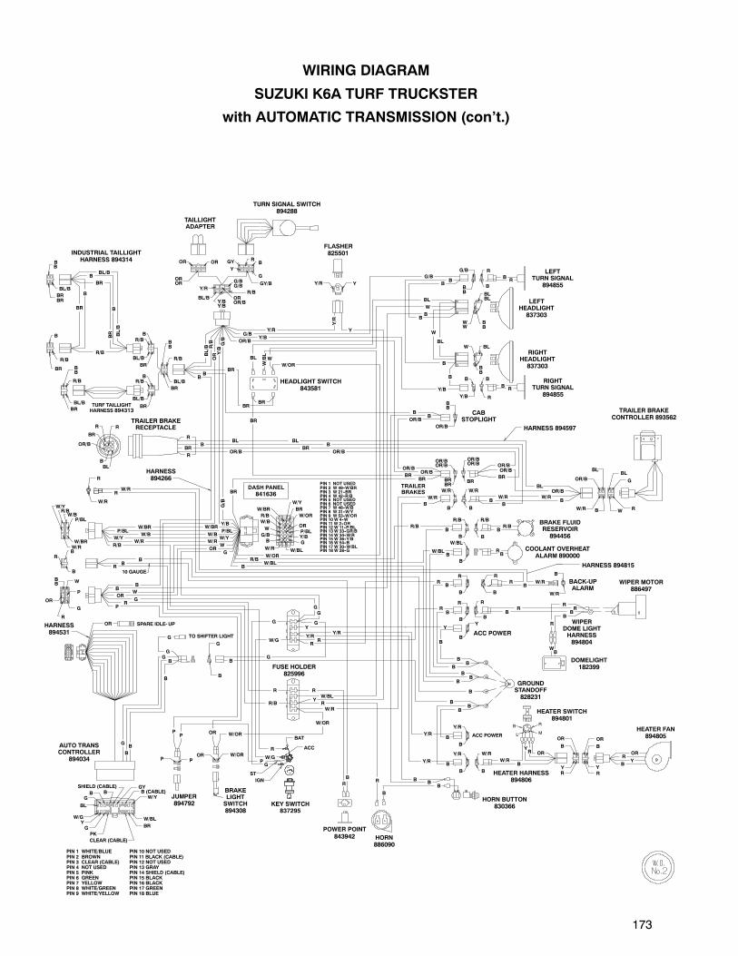
173
B
W/R
BACK-UPALARM
G
R
C
HEATER SWITCH894801
B
G
OR
ST
W/G
G
Y
Y/R
R
B
B
YR WIPER
DOME LIGHTHARNESS894804
B
BR
BL
OR
Y/B
P/BL
W/Y
W
10 GAUGE
W/Y
OR/B
B
CABSTOPLIGHT
B
BL
OR
WB
B
RR
BR
B
YR
ORRY
OR
BW/R
B
RW/R
W/RRB
B
B
Y/R
R/BB
B
B
B
B
B
B
BB
G
G
R
R
R
OR/B
R
ACC POWERY/R
Y/R
B
B
R
W
B
B
R
R
BR
BL
BL
RB
B
BL
BB
B
G/B
G/B
R
Y/R
BR
B
BR
R/B
B
BL/B
B
B
BL/B
BL/B
R/B
Y/R
W/BL
B
B
B
G
B
W/OR
R
R
R
R
Y
B
ACC POWER
W/OR
W/OR
OR
G
B
B
W/RW/RB
B
B
R
RP
G
G
WB
B
R/B
P/BL
PIN 1 NOT USEDPIN 2 W 49--W/BRPIN 3 W 21--BRPIN 4 W 42--R/BPIN 5 NOT USEDPIN 6 NOT USEDPIN 7 W 48--W/BPIN 8 W 31--W/YPIN 9 W 53--W/ORPIN 10 W 4--WPIN 11 W 2--ORPIN 12 W 11--P/BLPIN 13 W 33--GR/BPIN 14 W 34--W/RPIN 15 W 36--Y/BPIN 16 W 54--BPIN 17 W 30--W/BLPIN 18 W 28--G
W/BRW/BR
W/RW/R
W/BW/B
BR
BR
BR
B
G/B
BR
BR
BR B
OR/B
B
R
W/R
P
G
P
OR/B
R/B
OR/B
OR/B
Y/B
Y/B
G/B
Y/B
B
B
B
BL
BL
W
W
W/OR
Y
W/BL
BR
B
BR
B
W/G
P
W/R
B
B
B
W/BL
B
R/B
R/B
W/BL
OR/B
OR/B
BR
B
B
G
G
G TO SHIFTER LIGHT
OR
B
RR
R
Y
OR
B
RY
B
OR
W/R
B
R
W/R
B
GY/BOROR
OROR
BB
P
W
OR
R/B
B
BB
G/B
Y/B
R/B
W/BL
Y
R
Y/R
Y/R
B
B
B
B
B
B
B
B
G
ORP
W/ORP
B
BR
BL/B
R/BB
YY/R
IGN
ACC
BAT
W/R
OR/BBL
W R
G
BLW
BB
BLBL
WW
BB
R
R
BB
B
BLB
OR/B
BR
R R
OR/BOR/B
BB
W/RW/R
BL/B
R/B
BL/B
BR
BB
R/B
BR
BL/B
R/BB
RB
G
Y
GY
Y/R
BL/BY/BY/B
OROR/B
B
R
R
OR/BOR/B
BRBR
BR
W/RW/BR
P/BL
W/Y
W/BR/B
ORP/BL
W/Y
BR
Y/BB
W/BL
R/B
W/BR
W
G/B
GW/R
W/B
W/OR
G/BG/B
R/B
BL/B
BR
BB
R/B
W/GY
B
PK
G
B (CABLE)W/Y
GYSHIELD (CABLE)
BL
BG
CLEAR (CABLE)
BR
W/BL
SPARE IDLE- UP
TRAILER BRAKERECEPTACLE
PIN 1 WHITE/BLUEPIN 2 BROWNPIN 3 CLEAR (CABLE)PIN 4 NOT USEDPIN 5 PINKPIN 6 GREENPIN 7 YELLOWPIN 8 WHITE/GREENPIN 9 WHITE/YELLOW
PIN 10 NOT USEDPIN 11 BLACK (CABLE)PIN 12 NOT USEDPIN 13 GRAYPIN 14 SHIELD (CABLE)PIN 15 BLACKPIN 16 BLACKPIN 17 GREENPIN 18 BLUE
INDUSTRIAL TAILLIGHTHARNESS 894314B
B
BR
BRBR
B
TAILLIGHTADAPTER
TURN SIGNAL SWITCH894288
FLASHER825501
LEFTTURN SIGNAL
894855
LEFTHEADLIGHT837303
RIGHTTURN SIGNAL
894855
RIGHTHEADLIGHT837303
HARNESS 894597
TRAILER BRAKECONTROLLER 893562
BB
OR/B
OR/B
TRAILERBRAKES
HEADLIGHT SWITCH843581
TURF TAILLIGHTHARNESS 894313
HARNESS894266
DASH PANEL
841636
BRAKE FLUIDRESERVOIR894456
COOLANT OVERHEATALARM 890000
WIPER MOTOR886497
HARNESS 894815
DOMELIGHT182399
GROUNDSTANDOFF828231
FUSE HOLDER825996
HORN886090
POWER POINT843942
KEY SWITCH837295
BRAKELIGHTSWITCH894308
HARNESS894531
HEATER FAN894805
JUMPER894792
AUTO TRANSCONTROLLER
894034
L M
RB
HEATER HARNESS894806
HORN BUTTON830366
WIRING DIAGRAM
SUZUKI K6A TURF TRUCKSTER
with AUTOMATIC TRANSMISSION (con’t.)
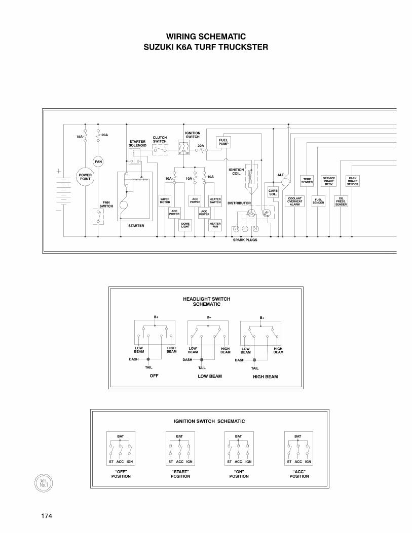
174
ALT.
SPARK PLUGS
DISTRIBUTOR
15A20A
FAN
STARTER
10A 10A10A
20A
ST IGN
LOWBEAM
HIGHBEAM
TAIL
DASH
B+
LOWBEAM
HIGHBEAM
B+
DASH
TAIL
HIGH BEAMLOW BEAM
B+
LOWBEAM
HIGHBEAM
DASH
TAIL
OFF
POWERPOINT
FANSWITCH
STARTERSOLENOID
CLUTCHSWITCH
IGNITIONSWITCH
IGNITIONCOIL
WIPERMOTOR
ACCPOWER
ACCPOWER
ACCPOWER
DOMELIGHT
HEATERFAN
HEATERSWITCH
CARBSOL.
TEMPSENDER
COOLANTOVERHEATALARM
FUELSENDER
OILPRESS.SENDER
SERVICEBRAKERESV.
PARKBRAKESENDER
HEADLIGHT SWITCHSCHEMATIC
WIRING SCHEMATIC
SUZUKI K6A TURF TRUCKSTER
FUELPUMP
ACC
IGNITION SWITCH SCHEMATIC
BAT
ACC IGNST
BAT
ACC IGNST
BAT
ACC IGNST
BAT
ACC IGNST
“OFF”POSITION
“START”POSITION
“ON”POSITION
“ACC”POSITION
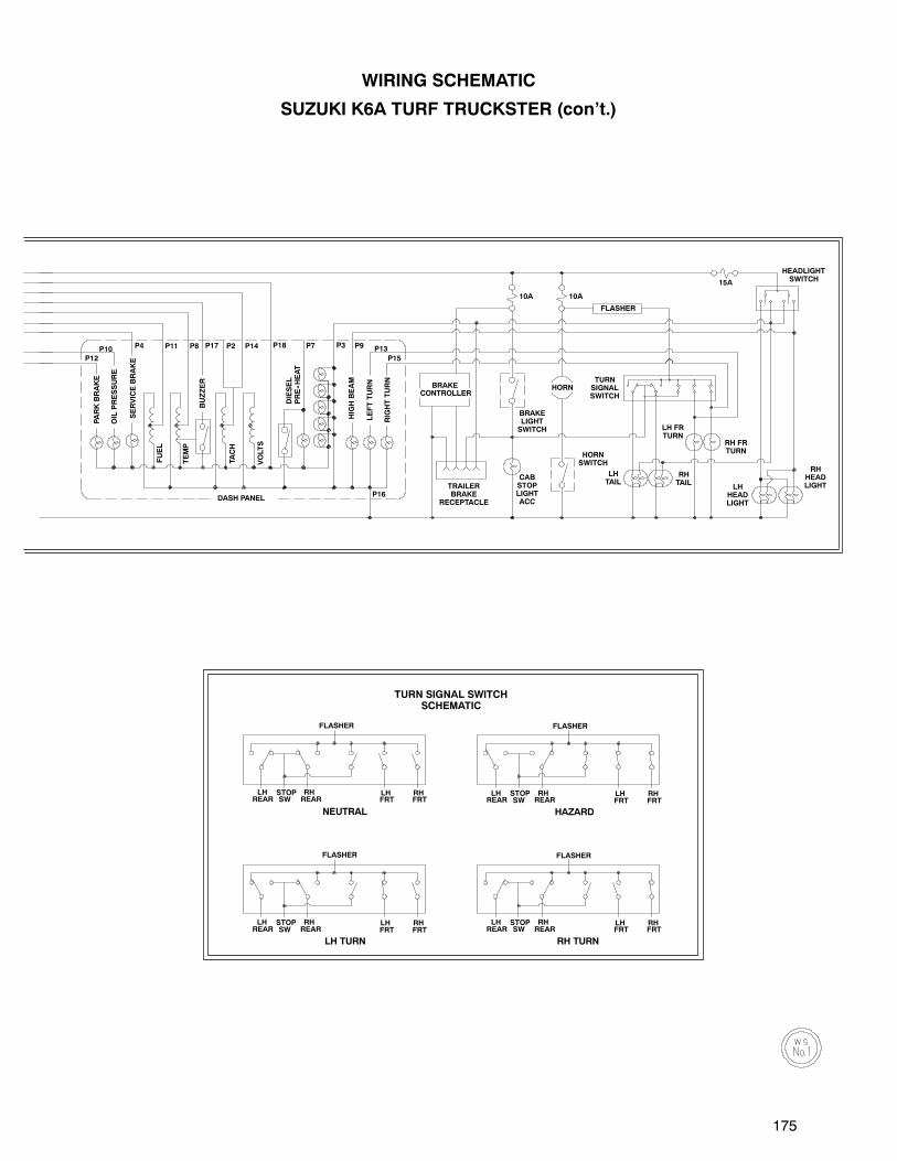
175
P15
P13
P16
P9P3P7P14P2P17P8P11P4 P18
P12
P10HIGHBEAM
10A
FLASHER
10A
15A
TACH
VOLTS
FUEL
BUZZER
PARKBRAKE
OILPRESSURE
TEMP
LEFTTURN
DIESEL
PRE--HEAT
RIGHTTURN
DASH PANEL
SERVICEBRAKE
BRAKECONTROLLER
HORN
LH FRTURN
RH FRTURN
RHTAIL
LHHEADLIGHT
TURNSIGNALSWITCH
BRAKELIGHTSWITCH
HORNSWITCH
LHTAIL
CABSTOPLIGHTACC
TRAILERBRAKE
RECEPTACLE
HEADLIGHTSWITCH
RHHEADLIGHT
LHREAR
STOPSW
RHREAR
LHFRT
RHFRT
LHREAR
STOPSW
RHREAR
LHFRT
RHFRT
LHREAR
STOPSW
RHREAR
LHFRT
RHFRT
NEUTRAL
LH TURN
HAZARD
RH TURN
FLASHER
FLASHER FLASHER
FLASHER
LHREAR
STOPSW
RHREAR
LHFRT
RHFRT
TURN SIGNAL SWITCHSCHEMATIC
WIRING SCHEMATIC
SUZUKI K6A TURF TRUCKSTER (con’t.)
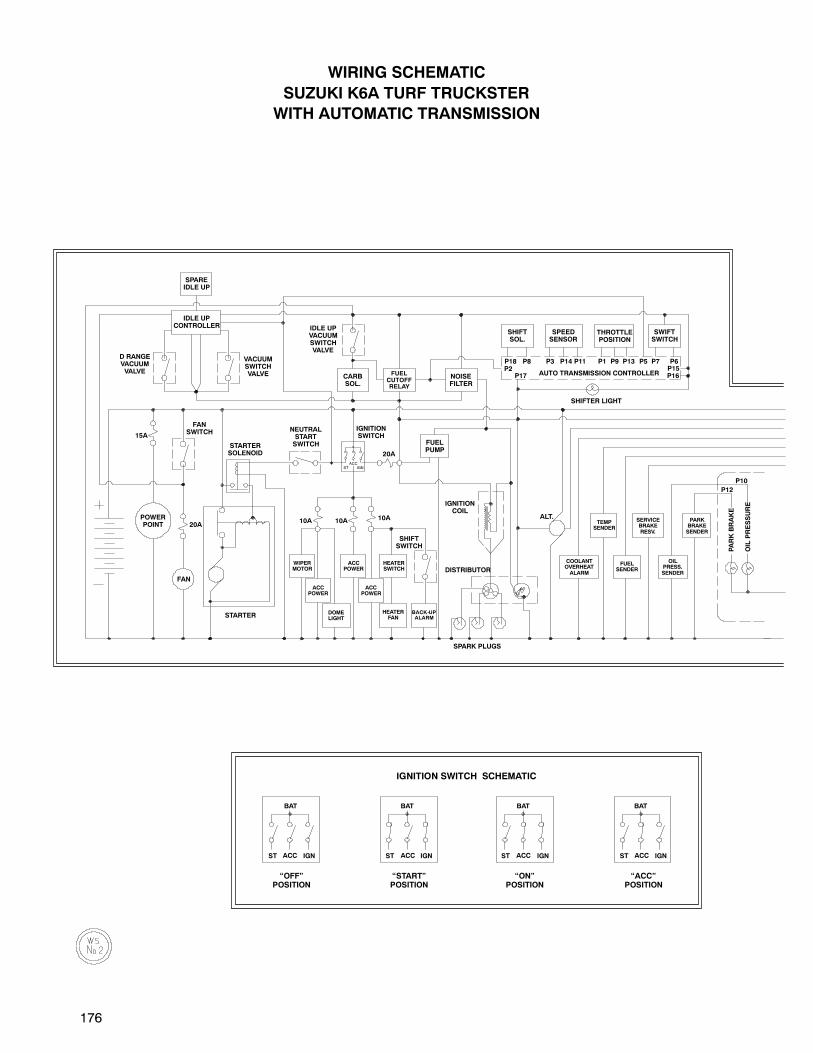
176
ST IGN
IGNITIONSWITCH
ACC
WIRING SCHEMATIC
SUZUKI K6A TURF TRUCKSTER
WITH AUTOMATIC TRANSMISSION
10A10A10A
P5P14
SHIFTER LIGHT
P17 P16P15P6P7P13P9P1P11P3P8P18
P2AUTO TRANSMISSION CONTROLLER
20A
20A
15A
ALT.
SPARK PLUGS
DISTRIBUTOR
P12
P10
FAN
STARTER
PARKBRAKE
OILPRESSURE
TEMPSENDER
COOLANTOVERHEATALARM
FUELSENDER
OILPRESS.SENDER
SERVICEBRAKERESV.
PARKBRAKESENDER
IGNITIONCOIL
WIPERMOTOR
ACCPOWER
ACCPOWER
ACCPOWER
DOMELIGHT
HEATERFAN
HEATERSWITCH
FUELPUMP
SHIFTSWITCH
NEUTRALSTARTSWITCHSTARTER
SOLENOID
FANSWITCH
POWERPOINT
SPAREIDLE UP
IDLE UPCONTROLLER
D RANGEVACUUMVALVE
VACUUMSWITCHVALVE
IDLE UPVACUUMSWITCHVALVE
CARBSOL.
FUELCUTOFFRELAY
NOISEFILTER
SHIFTSOL.
SPEEDSENSOR
THROTTLEPOSITION
SWIFTSWITCH
BACK-UPALARM
IGNITION SWITCH SCHEMATIC
BAT
ACC IGNST
BAT
ACC IGNST
BAT
ACC IGNST
BAT
ACC IGNST
“OFF”POSITION
“START”POSITION
“ON”POSITION
“ACC”POSITION

177
15A
10A10A
P15
P13
P16
P9P3P7P14P2P17P8P11P4 P18
HIGHBEAM
SERVICEBRAKE
FUEL
FLASHER
HORN
TACH
VOLTS
BUZZER
TEMP
LEFTTURN
DIESEL
PRE--HEAT
RIGHTTURN
DASH PANEL
BRAKECONTROLLER
TRAILERBRAKE
RECEPTACLE
BRAKELIGHTSWITCH
CABSTOPLIGHTACC
LH FRTURN
RH FRTURN
RHTAIL
LHHEADLIGHT
TURNSIGNALSWITCH
HORNSWITCH
LHTAIL
HEADLIGHTSWITCH
RHHEADLIGHT
LOWBEAM
HIGHBEAM
TAIL
DASH
B+
LOWBEAM
HIGHBEAM
B+
DASH
TAIL
HIGH BEAMLOW BEAM
B+
LOWBEAM
HIGHBEAM
DASH
TAIL
OFF
HEADLIGHT SWITCHSCHEMATIC
LHREAR
STOPSW
RHREAR
LHFRT
RHFRT
LHREAR
STOPSW
RHREAR
LHFRT
RHFRT
LHREAR
STOPSW
RHREAR
LHFRT
RHFRT
NEUTRAL
LH TURN
HAZARD
RH TURN
FLASHER
FLASHER FLASHER
FLASHER
LHREAR
STOPSW
RHREAR
LHFRT
RHFRT
TURN SIGNAL SWITCHSCHEMATIC
WIRING SCHEMATIC
SUZUKI K6A TURF TRUCKSTER
WITH AUTOMATIC TRANSMISSION (con’t.)

178
B
OR
W/Y
P/BLW/BR
W/R
W/B
R/B
W
G
OR
OR
W/B Y
YB
BR
BL/B
R/B
B
W
R
B
W/R
B
B/W BR
BR/B W/BR
B/W
GB
B
R10 GAUGE
W/BOR
ORBB
B
R/B
R
B
R
W
BL
B
OR/B
BR
R R
BR
B
OR
BL/B
B
BR
R/B
BRBR
B
BL/B
BR
BB
R/B
BR
BL/B
R/B
B
B 10 GAUGE
R
B
B
W/R
W/BR
P/BL
W/Y
W/BR/B
R
P/BL
P
B
G
P
W
W/Y
BB
B
B
R
R
R R
R
W
BRB/W
W/BR
G
G
G
G
OR
B
B
B
B
B
PB
Y
OR
OR
W/Y
W/Y
R
B
R
BBL/B
R/B
BB
RP
G
W
B
B
P/BL
P/BL
B
R
W/B
R
-+
R/B
G
R
P
R
W/R
R/B
R
B
B
B
B
BR
BR
OR/BBR
BBL
R
W/R
B
W/BR
B
B
W/R
W/BR
Left IndustrialTaillight 892676
Industrial TaillightHarness 892676
Right IndustrialTaillight 892676
Turf TaillightHarness 894313
Trailer BrakeReceptacle
Fan2700799
Fan Switch17680-50F70
Harness894201
Fuel LevelSender843298
Fuel Pump15100-53F03
EngineHarness894283
Starter31100-79X50
ParkBrake
Temp Sender843857
Coil33410-85010
Distributor33100-85750
Turf Taillight893602
Alternator31400-60C11
Start Solenoid889673
CarbSOL
WIRING DIAGRAM
SUZUKI 970 TURF TRUCKSTER
W/BRW/BR
G
COLOR CODE:
B - BLACK W - WHITE W/BR - WHITE w/BROWN STRIPE
BL - BLUE Y - YELLOW W/G - WHITE w/GREEN STRIPE
BR - BROWN BL/B - BLUE w/BLACK STRIPE W/OR - WHITE w/ORANGE STRIPE
G - GREEN G/B - GREEN w/BLACK STRIPE W/R - WHITE w/RED STRIPE
GY - GREY OR/B - ORANGE w/BLACK STRIPE W/Y - WHITE w/YELLOW STRIPE
OR - ORANGE P/BL - PURPLE w/BLUE STRIPE Y/B - YELLOW w/BLACK STRIPE
PK - PINK R/B - RED w/BLACK STRIPE Y/R - YELLOW w/RED STRIPE
P - PURPLE W/B - WHITE w/BLACK STRIPE
R - RED W/BL - WHITE w/BLUE STRIPE
20 AmpFuse
OilPressure

179
W/G
Heater Harness894806
Y
R/B
R R
B
W/R
BR
Y
R
Y
B
OR OR
B
OR
OROR
OR
R/B
B
BB
0R/B
R
B
Y/R
B
Y/R
B
Y/B
B
G/B
B
Y
B
W/BL
B
R/B
Y/R Y
ST
IGN
BAT
ACC
W/R B
OR/B
BLBL
WR
G
BLW
BB
BLBL
WW
BB
R
R
BB
BB
B
OR/BOR/B
BB
W/R
RB
G
GY/B
Y
GY
Y/R
BL/BY/BY/B
OROR/B
OR/BOR/B
BRBR
BR
OR
P/BL
W/Y
BR
Y/BB
W/BL
R/B
W/BR
W
G/B
G
W/R
W/B
W/OR
G/BG/B
R/B
BL/B
BR
BB
R/B
B
G
ORP
W/OR
P
WB
B
RB
RRB
RB
R OR
CRML
ORR
YB
W/RB
B
Y/R
BR/B
B
BB
B
B
B
B
BB
R
OR/B
R
Y/R
Y/R
B
B
Y/R
W
B
B
R
R
BR
BL
BL
RB
BL
BB
B
G/B
G/B
Y/R
BR
B
BR
R/B
B
BL/B
B
Y/R
B
W/BL
B
B
B
G
B
W/OR
Y
R
R
RR
R
Y
B
W/OR
W/OR
OR
G
B
W/RB
BB
R
G
G
G
ORW
R/B
PIN 1 NOT USEDPIN 2 W 49-W/BRPIN 3 W 21- BRPIN 4 W 42- R/BPIN 5 NOT USEDPIN 6 NOT USEDPIN 7 W 48-W/BPIN 8 W 31-W/YPIN 9 W 53-W/ORPIN 10 W 4-WPIN 11 W 2- ORPIN 12 W 11- P/BLPIN 13 W 33- GR/BPIN 14 W 34-W/RPIN 15 W 36- Y/BPIN 16 W 54- BPIN 17 W 30-W/BLPIN 18 W 28- G
W/BR
W/RW/Y
W/BP/BL
BR
BR
B
G/B
W/R
P
G
P
OR/BOR/B
OR/B
Y/B
Y/B
Y/B
G/B
OR
Y/B
OR/B
B
B
B
BL
BL
W
W
W/OR
Y
W/BL
BR
B
BR
B
B
W/G
Y
P
W/R
B
B
B
R
R
W/BL
B
R/B
G
W/BL
OR/B
OR/BOR/B
BR
TaillightAdapter
Turn SignalSwitch 894288
Flasher825501
Left TurnSignal
Left Headlight837303
Right Headlight837303
Right TurnSignal
Cab StopLight
Headlight Switch843581
BLB
OR/BBR
TrailerBrakes
W/R
Brake FluidReservoir 894456
CoolantOverheat Alarm
890000
Dash Panel841636
Power Point
R/B
WOR
G
PR
R
BB
BB
W/R
W/BW/Y
P/BLW/BR
Main Harness894266
Auto TranController
Acc Power
Acc Power
Wiper Motor886497
Wiper, DomeLight Harness
894804
Dome Light182399
Heater Fan894805
Heater Switch894801
Ground Standoff828231
Horn Button830366
Acc Power
Horn 886090
Power Point843942
Key Switch837295
Brake LightSwitch 894308
Clutch Switch894308
Trailer BrakeController893562
Harness894597
Fuse Holder825996
WIRING DIAGRAM
SUZUKI 970 TURF TRUCKSTER (con’t.)
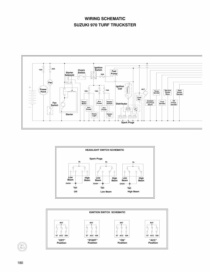
180
ALT.
15A20A
10A 10A10A
20A
ST IGN
DASH
B+B+
DASH
B+
DASH
PowerPoint
FanSwitch
StarterSolenoid
ClutchSwitch
IgnitionSwitch
IgnitionCoil
WiperMotor
AccPower
AccPower
AccPower
DomeLight
HeaterFan
HeaterSwitch
CarbSol.
TempSender
CoolantOverheatAlarm
FuelSender
OilPress.Sender
ServiceBrakeResv.
ParkBrakeSender
HEADLIGHT SWITCH SCHEMATIC
WIRING SCHEMATIC
SUZUKI 970 TURF TRUCKSTER
FuelPump
ACC
IGNITION SWITCH SCHEMATIC
BAT
ACC IGNST
BAT
ACC IGNST
BAT
ACC IGNST
BAT
ACC IGNST
“OFF”Position
“START”Position
“ON”Position
“ACC”Position
Fan
Distributor
Spark Plugs
Starter
Spark Plugs
LowBeam
HighBeam
LowBeam
HighBeam
LowBeam
HighBeam
TailTailTail
High BeamLow BeamOff
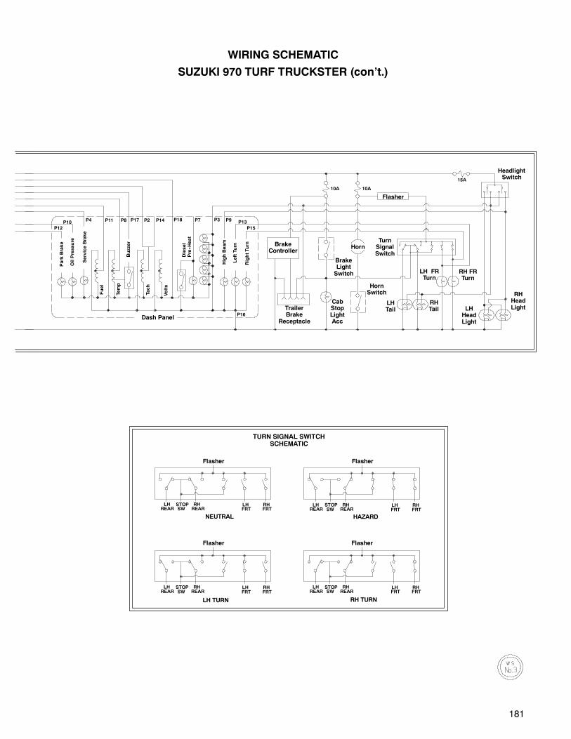
181
P15
P13
P16
P9P3P7P14P2P17P8P11P4 P18
P12
P10HighBeam
10A 10A
15A
Tach
Volts
Fuel
Buzzer
Park
Brake
OilPressure
Temp
LeftTurn
Diesel
Pre--Heat
RightTurn
ServiceBrake
LH FRTurn
RH FRTurn
RHTail LH
HeadLight
TurnSignalSwitch
BrakeLightSwitch
HornSwitch
CabStopLightAcc
TrailerBrake
Receptacle
HeadlightSwitch
RHHeadLight
LHREAR
STOPSW
RHREAR
LHFRT
RHFRT
LHREAR
STOPSW
RHREAR
LHFRT
RHFRT
LHREAR
STOPSW
RHREAR
LHFRT
RHFRT
NEUTRAL
LH TURN
HAZARD
RH TURN
LHREAR
STOPSW
RHREAR
LHFRT
RHFRT
TURN SIGNAL SWITCHSCHEMATIC
LHTail
BrakeController
Flasher
Dash Panel
Horn
Flasher Flasher
Flasher Flasher
WIRING SCHEMATIC
SUZUKI 970 TURF TRUCKSTER (con’t.)
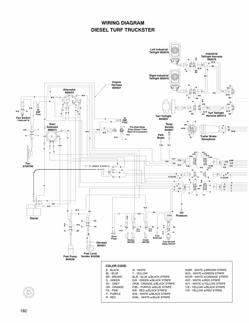
182
G
Y
W/G
RR
B
B
OR
W/Y
P/BLW/BR
W/R
W/B
R/B
W
G
OR
OR
BR
BL/B
R/B
B
W
R
B
W/R
R10 GAUGE
OR
ORB
B
R/B
R
B
R
W
BL
B
OR/B
BR
R R
BR
B
OR
BL/B
B
BR
R/B
BRBR
B
BL/B
BR
BB
R/B
BR
BL/B
R/B
B
B 10 GAUGE
R
B
B
W/R
W/BR
P/BL
W/Y
W/BR/B
R
P/BL
P
B
G
P
W
W/Y
BB
B
W/R
BS
EXC P
W/R
B
G
B
R
R
R
R
R
R
W
G
W/G
G
OR
B
B
B
B
B
B
P
G
OR
OR
W/Y
W/Y
R
B
R
BBL/B
R/B
BB
RP
G
W
B
B
P/BL
P/BL
R
R
-+
R/B
P
R
W/R
R/B
R
B
B
B
B
BR
BR
OR/BBR
BBL
R
W/R
B
B
W/R
Left IndustrialTaillight 892676
IndustrialTaillight Harness
892676
Right IndustrialTaillight 892676
Turf TaillightHarness 894313
Trailer BrakeReceptacle
Harness894201
Fuel LevelSender 843298Fuel Pump
894638
EngineHarness894637
Starter
ParkBrake
TempSender843857
Turf Taillight893602
Alternator893633
StartSolenoid889673
WIRING DIAGRAM
DIESEL TURF TRUCKSTER
W/GW/G
BL
W/G
Y
W/GW/G
G
WGG
GG BL
W/GBL
Y G
Y
G
W/G
GGG
W
W/B
W/B
W/GR
W/B
Y
W/G
W/B
R
R
R R
R
BRB
BB
W/G
W/G
B
W
Pre-Heat Relay(View Shown FromBack Of Connector)
40AMPFUSE
W/B Y
YB
BW/B
Y
W/B
Fan2700799
Fan Switch17680-50F70
20AMPFuse
R
B
GlowPlugs
Fuel ShutoffRelay 843167
FuelSolenoid
Diodes884398
Diode884398
COLOR CODE:
B - BLACK W - WHITE W/BR - WHITE w/BROWN STRIPE
BL - BLUE Y - YELLOW W/G - WHITE w/GREEN STRIPE
BR - BROWN BL/B - BLUE w/BLACK STRIPE W/OR - WHITE w/ORANGE STRIPE
G - GREEN G/B - GREEN w/BLACK STRIPE W/R - WHITE w/RED STRIPE
GY - GREY OR/B - ORANGE w/BLACK STRIPE W/Y - WHITE w/YELLOW STRIPE
OR - ORANGE P/BL - PURPLE w/BLUE STRIPE Y/B - YELLOW w/BLACK STRIPE
PK - PINK R/B - RED w/BLACK STRIPE Y/R - YELLOW w/RED STRIPE
P - PURPLE W/B - WHITE w/BLACK STRIPE
R - RED W/BL - WHITE w/BLUE STRIPE
OilPressure
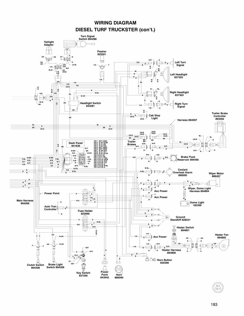
183
B
W/G
Heater Harness894806
Y
R/B
R R
B
W/R
BR
Y
R
Y
B
OR OR
B
OR
OROR
OR
R/B
B
BB
0R/B
R
B
Y/R
B
Y/R
B
Y/B
B
G/B
B
Y
B
W/BL
B
R/B
Y/R Y
ST
IGN
BAT
ACC
W/R B
OR/B
BLBL
WR
G
BLW
BB
BLBL
WW
BB
R
R
BB
BB
B
OR/BOR/B
BB
W/R
RB
G
GY/B
Y
GY
Y/R
BL/BY/BY/B
OROR/B
OR/BOR/B
BRBR
BR
OR
P/BL
W/Y
BR
Y/BB
W/BL
R/B
W/BR
W
G/B
G
W/R
W/B
W/OR
G/BG/B
R/B
BL/B
BR
BB
R/B
B
G
ORP
W/OR
P
WB
B
RB
RRB
RB
R OR
CRML
ORR
YB
W/RB
B
Y/R
BR/B
BB
B
B
B
B
BB
R
OR/B
R
Y/R
Y/R
B
B
Y/R
W
B
B
R
R
BR
BL
BL
RB
BL
BB
B
G/B
G/B
Y/R
BR
B
BR
R/B
B
BL/B
B
Y/R
B
W/BL
B
B
B
G
B
W/OR
Y
R
R
RR
R
Y
B
W/OR
W/OR
OR
G
B
W/RB
BB
R
G
G
G
ORW
R/B
PIN 1 NOT USEDPIN 2 W 49-W/BRPIN 3 W 21- BRPIN 4 W 42- R/BPIN 5 NOT USEDPIN 6 NOT USEDPIN 7 W 48-W/BPIN 8 W 31-W/YPIN 9 W 53-W/ORPIN 10 W 4-WPIN 11 W 2- ORPIN 12 W 11- P/BLPIN 13 W 33- GR/BPIN 14 W 34-W/RPIN 15 W 36- Y/BPIN 16 W 54- BPIN 17 W 30-W/BLPIN 18 W 28- G
W/BR
W/RW/Y
W/BP/BL
BR
BR
B
G/B
W/R
P
G
P
OR/BOR/B
OR/B
Y/B
Y/B
Y/B
G/B
OR
Y/B
OR/B
B
B
B
BL
BL
W
W
W/OR
Y
W/BL
BR
B
BR
B
B
W/G
Y
P
W/R
B
B
B
R
R
W/BL
B
R/B
G
W/BL
OR/B
OR/BOR/B
BR
TaillightAdapter
Turn SignalSwitch 894288
Flasher825501
Left TurnSignal
Left Headlight837303
Right Headlight837303
Right TurnSignal
Cab StopLight
Headlight Switch843581
BLB
OR/BBR
TrailerBrakes
W/R
Brake FluidReservoir 894456
CoolantOverheat Alarm
890000
Dash Panel841636
Power Point
R/B
WOR
G
PR
R
BB
BB
W/R
W/BW/Y
P/BLW/BR
Main Harness894266
Auto TranController
Acc Power
Acc Power
Wiper Motor886497
Wiper, Dome LightHarness 894804
Dome Light182399
Heater Fan894805
Heater Switch894801
GroundStandOff 828231
Horn Button830366
Acc Power
Horn886090
PowerPoint843942
Key Switch837295
Brake LightSwitch 894308
Clutch Switch894308
Trailer BrakeController893562Harness 894597
Fuse Holder825996
WIRING DIAGRAM
DIESEL TURF TRUCKSTER (con’t.)
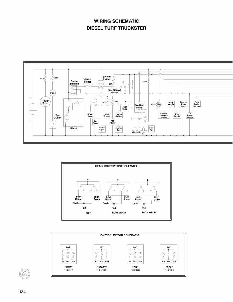
184
B+B+
HIGH BEAMLOW BEAM
B+
OFF
HEADLIGHT SWITCH SCHEMATIC
WIRING SCHEMATIC
DIESEL TURF TRUCKSTER
BAT
ACC IGNST
BAT
ACC IGNST
BAT
ACC IGNST
BAT
ACC IGNST
“OFF”Position
“START”Position
“ON”Position
“ACC”Position
15A20A
10A 10A10A
20A
ST IGN
PowerPoint
FanSwitch
StarterSolenoid
ClutchSwitch
IgnitionSwitch
WiperMotor
AccPower
AccPower
AccPower
DomeLight
HeaterFan
HeaterSwitch
TempSender
CoolantOverheatAlarm
FuelSender
OilPress.Sender
ServiceBrakeResv.
ParkBrakeSenderFuel
Pump
ACC
FuelSol.
40A
Glow Plugs
Pre-HeatRelay
Fuel ShutoffRelay
Starter
Fan
Alt.
Tail Tail Tail
HighBeam
HighBeam
HighBeam
Dash Dash Dash
LowBeam
LowBeam
LowBeam
IGNITION SWITCH SCHEMATIC
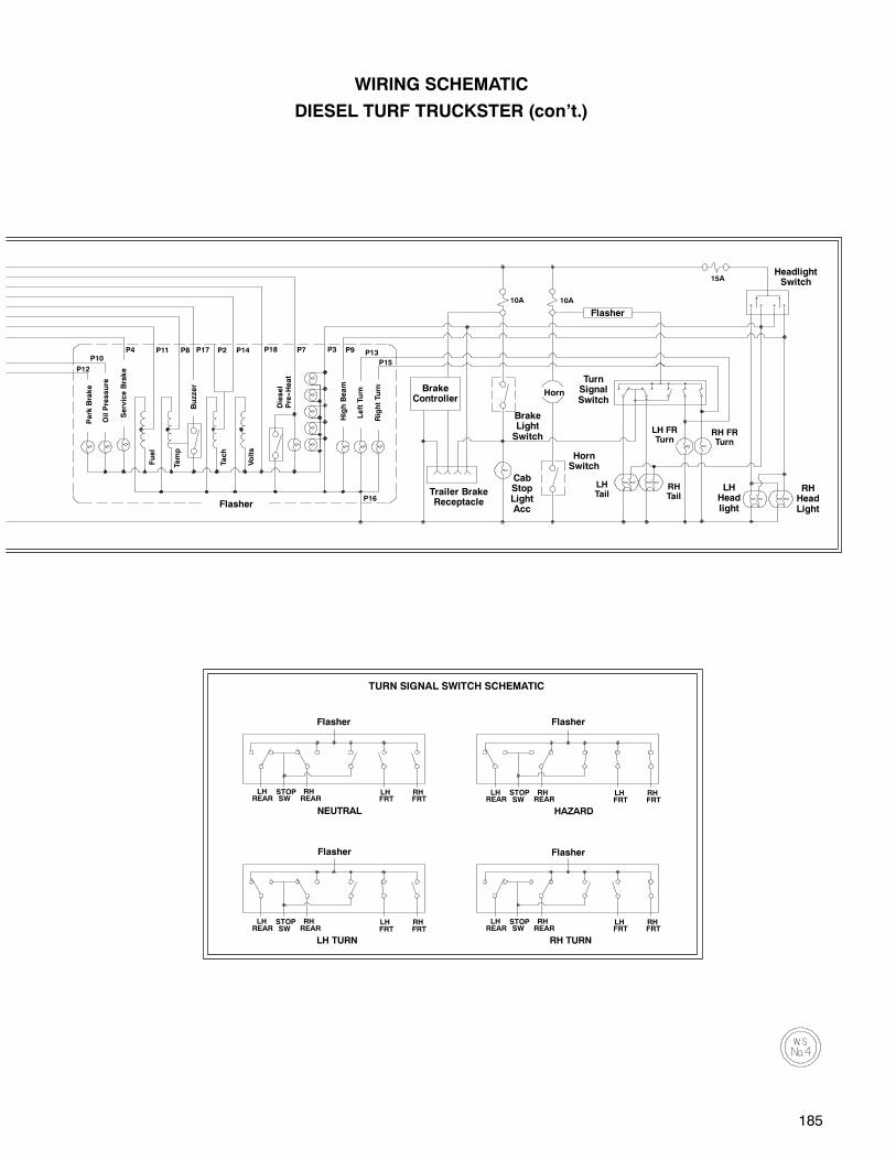
185
LHREAR
STOPSW
RHREAR
LHFRT
RHFRT
LHREAR
STOPSW
RHREAR
LHFRT
RHFRT
LHREAR
STOPSW
RHREAR
LHFRT
RHFRT
NEUTRAL
LH TURN
HAZARD
RH TURN
LHREAR
STOPSW
RHREAR
LHFRT
RHFRT
TURN SIGNAL SWITCH SCHEMATIC
P15
P13
P16
P9P3P7P14P2P17P8P11P4 P18
P12
P10
HighBeam
10A 10A
15A
Tach
Volts
Fuel
Buzzer
Park
Brake
OilPressure
Temp
LeftTurn
Diesel
Pre--Heat
RightTurn
ServiceBrake
LH FRTurn
RH FRTurn
RHTail
LHHeadlight
TurnSignalSwitch
BrakeLightSwitch
HornSwitch
LHTail
CabStopLightAcc
Trailer BrakeReceptacle
HeadlightSwitch
RHHeadLight
BrakeController
Horn
Flasher
Flasher
Flasher
Flasher
Flasher
Flasher
WIRING SCHEMATIC
DIESEL TURF TRUCKSTER (con’t.)

186
NOTES

Cushman Products
P.O. Box 388 Augusta, Georgia 30903--0388 USAInside USA Phone: 1--800--241--5855, FAX: 1--800--448--8124
Outside USA Phone: 010--1--706--798--4311, FAX: 010--1--706--771--4609
Copyrighted MaterialThis manual may not be reproduced in whole or
in part without the express permission ofE--Z--GO Division of Textron Inc.
Technical Communications Department