parts, operation and maintenance manual for …
TRANSCRIPT

R
Form MHD56227
PARTS, OPERATION AND MAINTENANCE MANUALfor
BUNDLE HANDLER
(Dwg. MHP2184)
Form MHD56227Edition 3October 201371374391© 2013 Ingersoll-Rand Company
READ THIS MANUAL BEFORE USING THESE PRODUCTS. This manualcontains important safety, installation, operation and maintenanceinformation. Make this manual available to all persons responsible for theinstallation, operation and maintenance of these products.
This equipment is intended for industrial use only and should not be used for lifting,supporting, or transporting people or lifting or supporting loads over people.
Always operate, inspect and maintain this unit in accordance with applicable safetycodes and regulations.

2 MHD56227 - Edition 3
SAFETY INFORMATION
This manual provides important information for all personnel involved with the safe installation, operation and proper maintenance of this product. Even if you feel you are familiar with this or similar equipment, you should read this manual before operating the product.
Danger, Warning, Caution and Notice
Throughout this manual there are steps and procedures which, if not followed, may result in a hazard. The following signal words
Indicates an imminently hazardous situation which, if not avoided, will result in death or serious injury.
Indicates a potentially hazardous situation which, if not avoided, could result in death or serious injury.
Indicates a potentially hazardous situation which, if not avoided, may result in minor or moderate injury or property damage.
Indicates information or a company policy that relates directly or indirectly to the safety of personnel or protection of property.
are used to identify the level of potential hazard.
Safety Summary
Personal protective and safety equipment should be used and maintained in accordance with the manufacturer’s instructions.
• Do not use this unit or attached equipment for lifting, supporting, or transporting people or lifting or supporting loads over people.• The supporting structures and load-attaching devices used in conjunction with these units must provide a safety factor of at least three times the rated capacity of the unit. This is the customer’s responsibility. If in doubt, consult a registered structural engineer.• If system air pressure is lost, lower the load immediately. The operator must stay out of the vertical path of the load.
• Lifting equipment is subject to different regulations in each country. These regulations may not be specified in this manual.
Employees who work near suspended loads or assist in positioning or arranging a load should be instructed to keep out from under the load. From a safety standpoint, one factor is paramount: conduct all lifting operations in such a manner that if there were an equipment failure, no personnel would be injured. This means keep out from under a raised load and keep out of the line of force of any load.
It is the owner’s and user’s responsibility to determine the suitability of a product for any particular use. It is recommended that all applicable industry, trade association, federal, state and local regulations be checked. Read all operating instructions and warnings before operation.
This manual has been produced by Ingersoll-Rand to provide dealers, mechanics, operators and company personnel with the information required to install, operate, maintain and repair the products described herein.
It is extremely important that mechanics and operators be familiar with the servicing procedures of these products, or like or similar products, and are physically capable of conducting the procedures. These personnel shall have a general working knowledge that includes:1. Proper and safe use and application of mechanics common
hand tools as well as special Ingersoll-Rand or recommended tools.
2. Safety procedures, precautions and work habits established by accepted industry standards.
Ingersoll-Rand cannot know of, or provide all the procedures by which product operations or repairs may be conducted and the hazards and/or results of each method. If operation or maintenance procedures not specifically recommended by the manufacturer are conducted, it must be ensured that product safety is not endangered by the actions taken. If unsure of an operation or maintenance procedure or step, personnel should place the product in a safe condition and contact supervisors and/or the factory for technical assistance.
MHD56227 - Edition 3 3
SAFE OPERATING INSTRUCTIONS
The following warnings and operating instructions are intended to avoid unsafe operating practices which might lead to injury or property damage.
Ingersoll-Rand recognizes that most companies who use material handling equipment have a safety program in force at their facility. If you are aware that some conflict exists between a rule set forth in this publication and a similar rule already set by an individual company, the more stringent of the two should take precedence.
The manual supports a fully installed system. Operators should be familiar with the operation of the controls before using the system.
Safe Operating Instructions are provided to make an operator aware of dangerous practices to avoid and are not necessarily limited to the following list. Refer to specific sections in the manual for additional safety information.1. Only allow personnel trained in, safety and operation on this
product to operate and maintain the system.2. Only operate bundle handler if you are physically fit to do
so.3. When a “DO NOT OPERATE” sign is placed on the
system, do not operate the bundle handler until the sign has been removed by designated personnel.
4. Before each shift, check the system for wear and damage. Never use a bundle handler that inspection indicates is worn or damaged.
5. Never lift a load greater than the rated capacity of the bundle handler. Refer to “SPECIFICATIONS” section.
6. When bundle handler is suspended from a wire rope, ensure load is centered. Do not “side pull” or “yard”.
7. Never operate a bundle handler which is suspended from twisted, kinked or damaged wire rope.
8. Pay attention to the load at all times when operating the bundle handler.
9. Make sure everyone is clear of the load path. Do not lift a load over people.
10. Never use the bundle handler for lifting or lowering people, and never allow anyone to stand on a suspended load.
11. Never weld or cut a load suspended by the bundle handler.12. Remove load and shut off air supply before performing any
maintenance.13. Do use good posture when operating the bundle handler.14. Check interlock for proper operation at first operation of
bundle handler.15. Do check air connections for leakage. 16. Check clamp for smooth operation.
WARNING LABELS
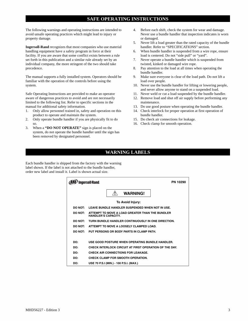
Each bundle handler is shipped from the factory with the warning label shown. If the label is not attached to the bundle handler, order new label and install it. Label is shown actual size.
PN 10290
To Avoid Injury:
DO NOT: LEAVE BUNDLE HANDLER SUSPENDED WHEN NOT IN USE.
DO NOT: ATTEMPT TO MOVE A LOAD GREATER THAN THE BUNDLER HANDLER’S CAPACITY.
DO NOT: TURN BUNDLE HANDLER CONTINUOUSLY IN ONE DIRECTION.
DO NOT: ATTEMPT TO MOVE A LOOSELY CLAMPED LOAD.
DO NOT: PUT PERSONS OR BODY PARTS IN CLAMP PATH.
DO: USE GOOD POSTURE WHEN OPERATING BUNDLE HANDLER.
DO: CHECK INTERLOCK CIRCUIT AT FIRST OPERATION OF THE DAY.
DO: CHECK AIR CONNECTIONS FOR LEAKAGE.
DO: CHECK CLAMP FOR SMOOTH OPERATION.
DO: USE 70 P.S.I (MIN.) - 100 P.S.I. (MAX.)
WARNING!!
4 MHD56227 - Edition 3
SPECIFICATIONS
Description
The bundle handler is an ergonomic handling device designed to move ‘Signature Bundles*’. The bundler handler incorporates either a single or dual air cylinder system to open and close clamping plates (paddles).
Bundle handlers are supplied with an interlock system to prevent accidental release of the bundle.
The bundle handler is designed to be supported by an Air Balancer and operated with an integral control system.
* A signature bundle or “Log” is a horizontal or vertical stack of paper usually from 24 in. (610 mm) to 48 in. (1219 mm) wide. The bundle is held together with a strap around the length, and has wood boards at each end. The stapled side of a signature is referred to as a spine.
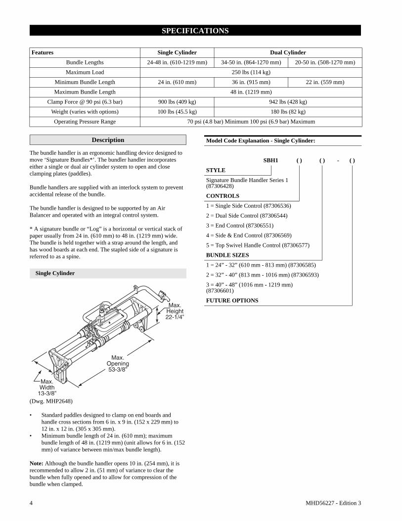
Single Cylinder
(Dwg. MHP2648)
• Standard paddles designed to clamp on end boards and handle cross sections from 6 in. x 9 in. (152 x 229 mm) to 12 in. x 12 in. (305 x 305 mm).
• Minimum bundle length of 24 in. (610 mm); maximum bundle length of 48 in. (1219 mm) (unit allows for 6 in. (152 mm) of variance between min/max bundle length).
Note: Although the bundle handler opens 10 in. (254 mm), it is recommended to allow 2 in. (51 mm) of variance to clear the bundle when fully opened and to allow for compression of the bundle when clamped.
Features Single Cylinder Dual Cylinder
Bundle Lengths 24-48 in. (610-1219 mm) 34-50 in. (864-1270 mm) 20-50 in. (508-1270 mm)
Maximum Load 250 lbs (114 kg)
Minimum Bundle Length 24 in. (610 mm) 36 in. (915 mm) 22 in. (559 mm)
Maximum Bundle Length 48 in. (1219 mm)
Clamp Force @ 90 psi (6.3 bar) 900 lbs (409 kg) 942 lbs (428 kg)
Weight (varies with options) 100 lbs (45.5 kg) 180 lbs (82 kg)
Operating Pressure Range 70 psi (4.8 bar) Minimum 100 psi (6.9 bar) Maximum
Model Code Explanation - Single Cylinder:
SBH1 ( ) ( ) - ( )
STYLE
Signature Bundle Handler Series 1(87306428)
CONTROLS
1 = Single Side Control (87306536)
2 = Dual Side Control (87306544)
3 = End Control (87306551)
4 = Side & End Control (87306569)
5 = Top Swivel Handle Control (87306577)
BUNDLE SIZES
1 = 24” - 32” (610 mm - 813 mm) (87306585)
2 = 32” - 40” (813 mm - 1016 mm) (87306593)
3 = 40” - 48” (1016 mm - 1219 mm) (87306601)
FUTURE OPTIONS
MHD56227 - Edition 3 5
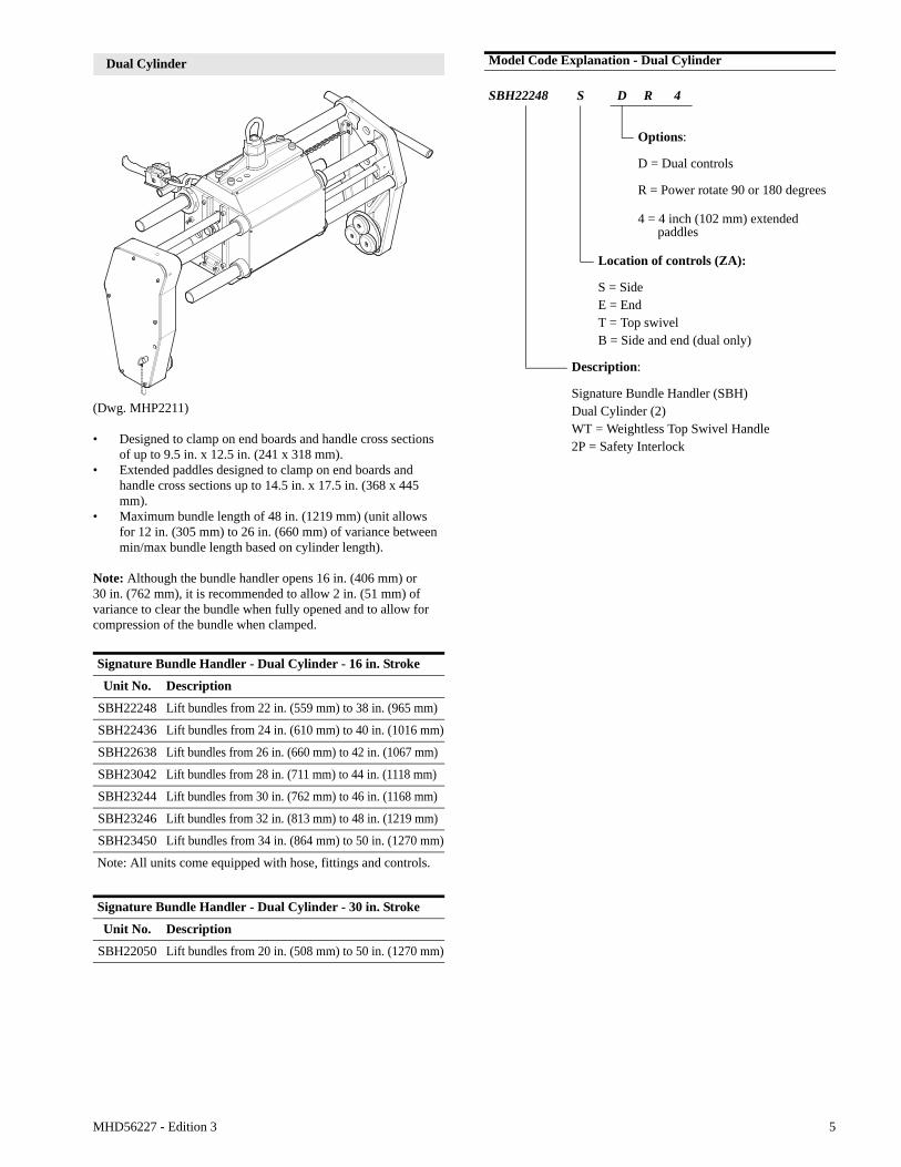
Dual Cylinder
(Dwg. MHP2211)
• Designed to clamp on end boards and handle cross sections of up to 9.5 in. x 12.5 in. (241 x 318 mm).
• Extended paddles designed to clamp on end boards and handle cross sections up to 14.5 in. x 17.5 in. (368 x 445 mm).
• Maximum bundle length of 48 in. (1219 mm) (unit allows for 12 in. (305 mm) to 26 in. (660 mm) of variance between min/max bundle length based on cylinder length).
Note: Although the bundle handler opens 16 in. (406 mm) or 30 in. (762 mm), it is recommended to allow 2 in. (51 mm) of variance to clear the bundle when fully opened and to allow for compression of the bundle when clamped.
Signature Bundle Handler - Dual Cylinder - 16 in. Stroke
Unit No. Description
SBH22248 Lift bundles from 22 in. (559 mm) to 38 in. (965 mm)
SBH22436 Lift bundles from 24 in. (610 mm) to 40 in. (1016 mm)
SBH22638 Lift bundles from 26 in. (660 mm) to 42 in. (1067 mm)
SBH23042 Lift bundles from 28 in. (711 mm) to 44 in. (1118 mm)
SBH23244 Lift bundles from 30 in. (762 mm) to 46 in. (1168 mm)
SBH23246 Lift bundles from 32 in. (813 mm) to 48 in. (1219 mm)
SBH23450 Lift bundles from 34 in. (864 mm) to 50 in. (1270 mm)
Note: All units come equipped with hose, fittings and controls.
Signature Bundle Handler - Dual Cylinder - 30 in. Stroke
Unit No. Description
SBH22050 Lift bundles from 20 in. (508 mm) to 50 in. (1270 mm)
Model Code Explanation - Dual Cylinder
SBH22248 S D R 4
Options:
D = Dual controls
R = Power rotate 90 or 180 degrees
4 = 4 inch (102 mm) extended paddles
Location of controls (ZA):
S = SideE = EndT = Top swivelB = Side and end (dual only)
Description:
Signature Bundle Handler (SBH)Dual Cylinder (2)WT = Weightless Top Swivel Handle2P = Safety Interlock

6 MHD56227 - Edition 3
INSTALLATION
Prior to installing unit, carefully inspect it for possible shipping damage.
• Owners and users are advised to examine specific, local or other regulations, including American National Standards Institute and/or OSHA Regulations which may apply to a particular type of use of this product before installing or putting the unit into use.• A falling load can cause injury or death. Before installing, read “SAFETY INFORMATION”.
Ensure unit is properly installed. A little extra time and effort in doing so can contribute a lot toward preventing accidents, injuries and will help achieve the best service possible.
Always make certain the supporting member from which the unit is suspended is strong enough to support the weight of the unit plus the weight of a maximum rated load plus a generous factor of at least 300% of the combined weights. If in doubt, contact a registered structural engineer.
Positioning the Load Hook
To correctly install and position load hook to wire rope you must determine the following:1. Highest point which load (bundle) must clear from floor
(Dimension 1). Refer to Dwg. MHP2393 on page 6.2. Distance from hook throat to bottom of load (bundle)
(Dimension 2). Refer to Dwg. MHP2394 on page 6.
(Dwg. MHP2393)
(Dwg. MHP2394)
3. Add dimension 1 to dimension 2, then add 3-1/2 inches (89 mm).
4. Measuring from the floor with the wire rope fully retracted, install hook using the dimension established in step 3. Refer to Balancer Parts, Operation and Maintenance Manual Form No. MHD56151 for hook installation information.
Mounting The Unit
Insert load hook through lifting eye in bundle handler. Ensure bundle handler lifting eye is fully seated in load hook and that hook latch is resting on hook tip. Ensure bundle handler hangs freely in a horizontal position and does not tilt to one side or the other. Remove the ZA control manifold from the packaging. Ensure there is an ‘O’ ring on the back of the manifold at the balancer port. Install manifold using 4 mounting screws and lock washers. The white hose will be installed in the port to the left of the manifold.
Air System
The air supply system should be purged for a minimum of 30 seconds prior to the connection of the balancer and bundle handler. This will remove any debris from the air lines and help prevent damage to the controls at start up. Zim-Air Balancers require 1/8 of a cubic ft. of air per cycle.
A minimum of 70 psi (4.8 bar) is recommended.
The balancer reaches maximum capacity when 100 psi (6.9 bar) is applied, as air pressure decreases the unit capacity decreases proportionally. If 80 psi (5.5 bar) is applied to the balancer you will obtain 80% of rated capacity.
For a more detailed principle of operation refer to the Ingersoll-Rand Balancer Service Manual Form No. MHD56151.
• Do not exceed 100 psig (6.9 bar/690 kPa) inlet pressure. Do not use a lubricator of any kind. Oil will damage internal components.• The air supply must be clean and free from water and water vapor.
Obstruction
Load
#1
Load#2
MHD56227 - Edition 3 7
Air Lines
The inside diameter of unit air supply lines must not be smaller than 3/8 inch (10 mm) based on a maximum of 100 feet (30 m) of air line between air supply and unit. Contact factory for recommended air line sizes for distances greater than 100 feet (30 m). Before making final connections, all air supply lines should be purged. Supply lines should be as short and straight as installation conditions will permit. Long transmission lines and excessive use of fittings, elbows, tees, globe valves, etc. cause a reduction in pressure due to restrictions and surface friction in the lines. If quick-disconnect fittings are used at the inlet of the unit, they must have at least a 3/16 inch (10 mm) air passage. Use of smaller fittings will reduce performance.
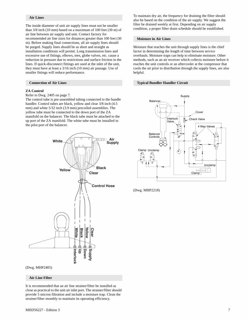
Connection of Air Lines
ZA ControlRefer to Dwg. 2405 on page 7.The control tube is pre-assembled tubing connected to the bundle handler. Control tubes are black, yellow and clear 3/8 inch (4.5 mm) and white 5/32 inch (3.9 mm) precoiled assemblies. The yellow tube must be connected to the down port of the ZA manifold on the balancer. The black tube must be attached to the up port of the ZA manifold. The white tube must be installed in the pilot port of the balancer.
(Dwg. MHP2405)
Air Line Filter
It is recommended that an air line strainer/filter be installed as close as practical to the unit air inlet port. The strainer/filter should provide 5 micron filtration and include a moisture trap. Clean the strainer/filter monthly to maintain its operating efficiency.
To maintain dry air, the frequency for draining the filter should also be based on the condition of the air supply. We suggest the filter be drained weekly at first. Depending on air supply condition, a proper filter drain schedule should be established.
Moisture in Air Lines
Moisture that reaches the unit through supply lines is the chief factor in determining the length of time between service overhauls. Moisture traps can help to eliminate moisture. Other methods, such as an air receiver which collects moisture before it reaches the unit controls or an aftercooler at the compressor that cools the air prior to distribution through the supply lines, are also helpful.
Typical Bundler Handler Circuit
(Dwg. MHP2218)
Interlo
ck
Do
wn
Up
Su
pp
ly
Yellow Black
White AirSupply
Control Hose
Clear
Black
Wh
ite
Yellow
Clear
V
VDN UP
Check Valve
Cover
Supply
4 Way Valves
InterlockValve
Clamp Unclamp
Unclamp
Clamp
Balancer
BalancerControls
8 MHD56227 - Edition 3
OPERATION
Description Of Operation
Bundle Handler
The bundle handler is an integrated group of components designed to maximize the interaction of man and machine. These components can be mounted to an overhead rail system on which the Ingersoll-Rand Balancer travels. The balancer has a wire rope with load hook attached to the bundle handler. The operator controls the system by use of the Ingersoll-Rand ZA (Zim-Air) up and down control to lift a bundle of signatures onto a stream feeder or directly to a gather in feed shelf. The clamp is actuated by push button or lever valves.
The system renders the bundles virtually weightless through the balancer’s compressed air operation. The rail system or Manipulator Arm provides for ease of horizontal movement. This combination requires little physical strength to operate and reduces operator fatigue.
The bundle handler should not be left suspended when not in use. Lower device to the floor or a suitable location out of the work area. Always use good posture when operating the Bundler Handler.
The suspended bundle must have a clear passage from a pick up point to a set down point. The suspended bundle can be raised or lowered approximately twelve inches from which it has been raised by gently nudging the load up or down. This is known as floating. Use of the controls is not required for this operation, just pressure applied to the load by the operator in the desired direction.
Balancer
Energy used to power the balancer is compressed air, a minimum of 70 psig (4.8 bar/480 kPa) is required. Air is controlled by an external control package. Compressed air pushes against the piston, causing it to move laterally.
The piston pushes the reel assembly causing the reel to move laterally as well as rotate which winds the wire rope into the balancer, raising the bundle handler. Compressed air is released through the controls to atmosphere and the reel rotates in the opposite direction lowering the bundle handler.
The balancer reaches maximum capacity when 100 psig (6.9 bar/690 kPa) is applied. As air pressure decreases the unit capacity decreases proportionally. If 80 psig (5.5 bar/552 kPa) is applied to the balancer, maximum balancer operational capacity is 80% of rated capacity.
For additional information, refer to the Balancer Parts, Operation and Maintenance manual, form number MHD56151.
Control Types
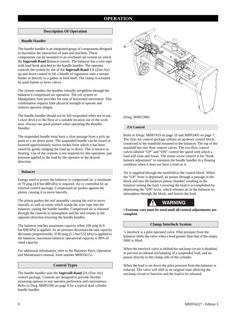
The bundle handler uses the Ingersoll-Rand ZA (Zim-Air) control package. Controls are designed to provide flexible mounting options to suit operator preference and convenience. Refer to Dwg. MHP2396 on page 8 for a typical dual cylinder bundle handler.
(Dwg. MHP2396)
ZA Control
Refer to Dwgs. MHP1819 on page 10 and MHP2405 on page 7.The Zim-Air control package utilizes an up/down control block, connected to the manifold mounted to the balancer. The top of the manifold has two flow control valves. The two flow control valves labeled “UP” and “DN” control the speed with which a load will raise and lower. The center screw control is for “hook balance adjustment” to maintain the bundle handler in a floating condition when it does not have a load on it.
Air is supplied through the manifold to the control block. When the “UP” lever is depressed, air passes through a passage in the block and into the balancer piston chamber resulting in the balancer raising the load. Lowering the load is accomplished by depressing the “DN” lever, which releases air in the balancer to atmosphere through the block, and lowers the load.
• Extreme care must be used until all control adjustments are complete.
Clamp Interlock System
’s interlock is a pilot operated valve. Pilot pressure from the balancer shifts the valve when a load greater than that of the empty SBH is lifted.
When the interlock valve is shifted the unclamp circuit is disabled, to prevent accidental unclamping of a suspended load, and air passes directly to the clamp side of the cylinder.
When the load is set down the pilot pressure from the balancer is reduced. The valve will shift to its original state allowing the unclamp circuit to function and the load to be released.

MHD56227 - Edition 3 9
Bundle Handler Operation
• If bundle is not held securely by Signature Bundle Handler and slips out of clamp, the empty handler will rise rapidly with the approximate force of the load.• If system air pressure is lost, lower load immediately. The operator must stay out of the vertical path of the bundle handler and load. Clamp may lose force required to hold load which can cause severe injury or property damage.
The “UP” and “DN” levers allow adjustable speed control. As the lever is depressed further, the operational speed increases. Use the lever to ‘throttle’ the speed to ensure controlled movement of the bundle handler.
(Dwg. MHP2406)
• Do not wrap control hoses around wire rope. Damage to hoses and failure of bundle handler may result.
Proper turning of the bundle handler prevents twisting and wear of the balancer wire rope and air control lines. Do not attempt to continuously turn in one direction; rather reverse direction with each cycle.
Raising and lowering of the bundle handler is dependent on the type of control circuit on the handling device. The Zim-Air (ZA) type control requires manual lever operation to raise and lower the bundle handler. 1. Move bundle handler to the pick up point, and position it
over the bundle for pick up. Actuate clamp open button or lever on control pendant.
• To prevent uncontrolled movement use both hands on the bundle handler when activating the clamp and rotate functions.• Never attempt to lift a loosely clamped bundle. Rapid acceleration of the Signature Bundle Handler may cause the bundle to drop.• Persons and body parts should never be in the path of the clamp paddles during operation. The clamp closes with extreme force and could result in injury.
2. Slowly lower bundle handler and engage the bundle. Center the clamp paddles on the end boards of the bundle. Actuate the clamp close button or lever and ensure bundle is securely clamped. If this is the first use of the SBH for the day, the (safety) interlock circuit should be tested. Depress the up lever to raise the bundle approximately 6 inches (152 mm) above the pick up point. Then actuate the cylinder clamp open button or lever. The clamp should not open and air should be heard exhausting from the clamp valve. If the clamp opens, notify maintenance personnel immediately.
• The suspended load may be raised or lowered approximately 12 inches (305 mm) by pushing or pulling the bundle in the desired direction.• The empty Signature Bundle Handler should not be left suspended when not in use. Lower the Signature Bundle Handler to the floor or pallet out of the work area.
3. Raise bundle handler to clear the pick up point and maneuver to the set down point.
4. At the set down point depress the down lever and lower the bundle completely.
5. Actuate the clamp open button or lever while continuing to depress the down lever to unclamp and disengage the bundle. Maneuver the bundle handler back to the pick up point and repeat steps.
Power Rotate Paddle (optional feature)
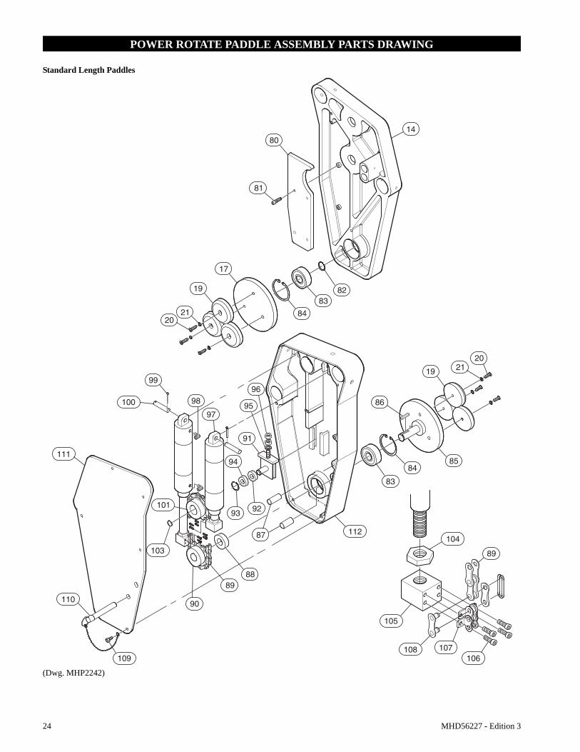
Refer to Dwgs. MHP2242 on page 24 and MHP2407 on page 9.The power rotate optional feature allows the bundle to be rotated a maximum of 180°.Install the detent pin (110) in the paddle cover upper hole when not required or when using the full 180° rotate.Install the detent pin (110) in the paddle cover lower hole to stop rotation at 90°.
Ensure detent pin is pushed all the way in to engage detents.
(Dwg. MHP2407)
Install detent pin in lower hole to stop rotation at 90˚
Stow pin in upper hole whennot in use

10 MHD56227 - Edition 3
Operation Adjustments
• Air supply pressure must be a minimum of 70 psig (4.8 bar/480 kPa) and a maximum of 100 psig (6.9 bar/690 kPa). Excessive air pressure may damage the balancer or controls.• Prior to adjustment of controls, ensure air is off and wire rope is slack.• The interlock should not be adjusted until all control adjustments have been completed. The interlock may not function properly if it is set before the controls.
• When wire rope is winding into the balancer, air is passing through both up and down flow controls. If the up speed is too fast you may rotate the down control clockwise to decrease the up speed.
ZA Control
Refer to Dwg. MHP1819 on page 10.1. On top of the ZA manifold are three screw type adjustable
controls. Turn the “UP” and “DOWN” control screws clockwise until fully closed. Then turn each control screw counterclockwise one full turn.
(Dwg. MHP1819)
2. The center control screw is for hook balance adjustment. The screw head should be flush with the top of the manifold body.
• The screw type control and hook balance adjustment screws on the ZA manifold should never extend above the manifold body. Thread engagement will be minimal and could result in the screw being discharged from the manifold.
3. Turn on air supply. Adjust supply pressure to highest maintainable; do not exceed 100 psig (6.9 bar/690 kPa).
4. To set hook balance, adjust hook balance screw, by turning clockwise, until empty handling device begins to rise. Slowly adjust screw, by turning counterclockwise, until device stops moving.
5. Depress “DOWN” lever on the ZA control block. Adjust “DOWN” control screw, by turning counterclockwise, until desired down speed is reached.
6. Depress “UP” lever on the ZA control block. Adjust “UP” control screw, by turning counterclockwise, until desired speed is achieved.
Interlock Clamp Adjustment
• The interlock should not be adjusted until all control adjustments have been completed.
• It may be necessary to actuate clamp and unclamp button/lever several times to obtain the correct interlock setting.• Interlock is only present on ZA controlled bundle handlers.
1. With empty bundle handler device suspended by the balancer, adjust interlock adjustment screw, by turning counterclockwise, until 3/4 inch (19 mm) of thread is visible.
2. While cycling clamp and unclamp functions, turn interlock adjustment screw clockwise until both clamp and unclamp circuits function.
3. Cycle clamp/unclamp switch several times to ensure smooth operation and that the interlock valve is shifting completely.
4. Raise empty bundle handler to its up stop. Depress ‘UP’ lever for 3 to 4 seconds to simulate a load on the balancer.
5. Actuate clamp and unclamp circuits. Clamp should not open. Air may be heard discharging to the atmosphere.
6. If clamp does open, repeat this adjustment procedure until clamp does not open with bundle handler at the up stop.
7. Once interlock valve is adjusted correctly, hold interlock stem with a suitable pair of pliers and tighten 3/8 inch jam nut on interlock adjustment screw to prevent setting from changing. Repeat the interlock test to ensure the setting did not change when the jam nut was tightened.
Platform Adjustment
If the platform is set too low the bundle may split out toward the platform. If the platform is set too high the bundle will split out toward the floor.
Manual PlatformRefer to Dwg. MHP2210 on page 20. Platform (57) position is fixed (located) by a plunger (36) at each end. A limited amount of adjustment is available in either direction. The platform is factory set so that the gripper pads on the paddles align with the base of the bundle, to prevent the log from “splitting” out.
No adjustment should be necessary unless the log height changes.
If adjustment is required, pull both plungers (36) out while pushing up or down on the platform (57). Release the plungers and continue to move the platform until plungers fully engage the next hole position. Typically holes are spaced at 2 in. (51 mm) intervals.
AirSupply
Flow ControlValve Flow Control
Valve
HookBalance
DOWNAir Line
Connection
UPAir Line
Connection
MHD56227 - Edition 3 11
Power PlatformRefer to Dwg. MHP2285 on page 28.The power platform is adjusted by the threaded rod (84). The jam nuts (88) that thread onto the rods (84) act as stops for the air cylinders (83). The platform is factory set so that the gripper pads on the paddles align with the centerline of the bundle, to prevent the log from “splitting” out.
No adjustment should be necessary unless the log height changes.
Minor adjustment can be made by changing the position of the jam nuts (88) on threaded rods (84) to shorten the stroke of the air cylinders (83). The gripper pads on the paddles must align with the centerline of the bundle. When correct adjustment is achieved tighten jam nuts. Ensure platform is adjusted equally at both ends.
Yarding
• Do not operate bundle handler if load is not centered under Balancer wire rope. Yarding of the wire rope will cause premature wear to wire rope and Balancer wire rope guides.
Wire rope should not be yarded more than 10 degrees from vertical.
Excessive yarding may create unsafe operation, cause increased wear on balancer and decrease working life of related components.

12 MHD56227 - Edition 3
INSPECTION
• All new or repaired equipment should be inspected and tested by personnel instructed in safety, operation and maintenance of this equipment to ensure safe operation at rated specifications before placing equipment is service.• Never use a unit that inspection indicates is damaged.
Frequent and periodic inspections should be performed on equipment in regular service. Frequent inspections are visual examinations performed by operators or personnel trained in safety and operation of this equipment and include observations made during routine equipment operation. Periodic inspections are thorough inspections conducted by personnel trained in the safety, operation and maintenance of this equipment. Inspection intervals will depend upon the nature of the critical components of the equipment and the severity of usage.
Careful inspection on a regular basis will reveal potentially dangerous conditions while still in the early stages, allowing corrective action to be taken before the condition becomes dangerous.
Deficiencies revealed through inspection, or noted during operation, must be reported to designated personnel instructed in safety, operation and maintenance of this equipment. A determination as to whether a condition constitutes a safety hazard must be decided, and the correction of noted safety hazards accomplished and documented by written report before placing the equipment in service.
Records and Reports
Inspection records, listing all points requiring periodic inspection should be maintained for all load bearing equipment. Written reports, based on severity of service, should be made on the condition of critical parts as a method of documenting periodic inspections. These reports should be dated, signed by the person who performed the inspection, and kept on file where they are readily available for authorized review.
Frequent Inspections
For equipment in continuous service, frequent inspections should be made by operators at the beginning of each shift.1. OPERATION. Check for visual signs or poor movement
which could indicate a potential problem. Make sure all controls function properly. Check bundle handler swivels freely through 90 degrees.
2. INTERLOCK (Safety Circuit). ZA Controls only. Test operation with no load. Raise empty bundle handler to the “UP” stop. With “UP” lever depressed for 3 to 4 seconds (to simulate load), actuate clamp and unclamp circuit. Clamp should not open. Refer to “OPERATION” section, ‘Interlock’ for correction instructions.
3. AIR SYSTEM. Visually inspect all connections, fitting, hoses and components for indication of air leaks. Repair any leaks or damage, tighten any loose connections.
4. BALANCER. Follow inspection recommendations in Balancer Parts, Operation and Maintenance Manual form MHD56151.
5. GUIDE BARS. Ensure guide bars are clean and lubricated. Clean guide bars when dirty or binding occurs. Use a multipurpose synthetic lubricant to lubricate guide bars.
6. WIRE ROPE. Inspect for wear and lubrication. Replace kinked, frayed or twisted wire rope.
Periodic Inspection
Frequency of periodic inspection depends on the severity of usage:
Disassembly may be required for HEAVY or SEVERE usage. Keep accumulative written records of periodic inspections to provide a basis for continuing evaluation.
Inspect all items in “Frequent Inspection”. Also inspect the following:1. FASTENERS. Check all rivets, split pins, capscrews and
nuts. Replace if missing or tighten if loose.2. ALL COMPONENTS. Inspect for wear, damage,
deterioration, deformation and cleanliness. If external evidence indicates the need, disassemble. Check handles, housings, bearings, springs, clamp pads and covers. Replace worn or damaged parts. Clean, lubricate and reassemble.
3. SUPPORTING STRUCTURE. Check for distortion, wear and continued ability to support load.
4. LABELS AND TAGS. Check for presence and legibility of labels. Replace if damaged or missing.
5. BALANCER. Follow inspection recommendations in Balancer Parts, Operation and Maintenance Manual form MHD56151.
6. POWER ROTATE (optional feature). Inspect for proper operation and leakage.
7. COVERS. Check covers are installed and secure. Replace if damaged or missing.
8. ZA CONTROL HANDLE. Check for tubing leaks and security of connections. Ensure levers operate freely.
Units Not in Regular Use
1. Units which have been idle for a period of one month or more, but less than one year, should be given an inspection conforming with the requirements of “Frequent Inspection” prior to being placed into service.
2. Units which have been idle for a period of more than one year should be given an inspection conforming with the requirements of “Periodic Inspection” prior to being placed into service.
3. Standby units should be inspected at least semiannually in accordance with the requirements of “Frequent Inspection”. In abnormal operating conditions, units should be inspected at shorter intervals.
NORMAL HEAVY SEVEREYearly Semiannually Quarterly
MHD56227 - Edition 3 13
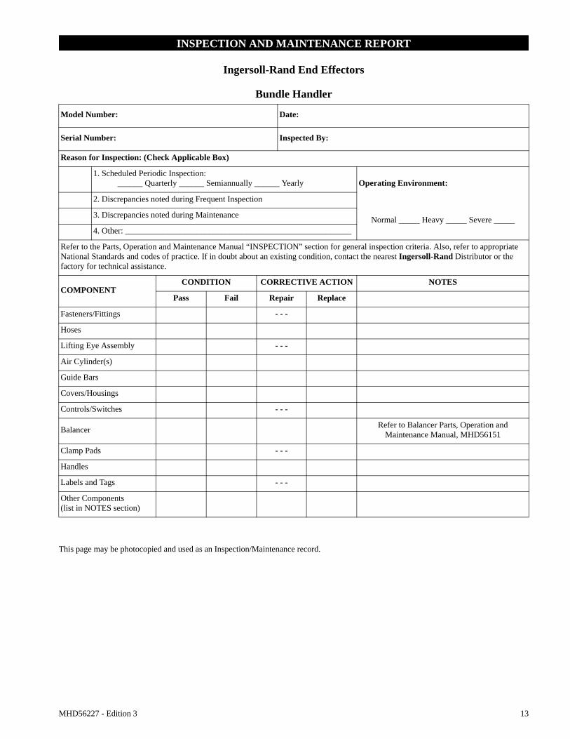
INSPECTION AND MAINTENANCE REPORT
Ingersoll-Rand End Effectors
Bundle Handler
This page may be photocopied and used as an Inspection/Maintenance record.
Model Number: Date:
Serial Number: Inspected By:
Reason for Inspection: (Check Applicable Box)
1. Scheduled Periodic Inspection:______ Quarterly ______ Semiannually ______ Yearly Operating Environment:
2. Discrepancies noted during Frequent Inspection
Normal _____ Heavy _____ Severe _____3. Discrepancies noted during Maintenance
4. Other: ______________________________________________________
Refer to the Parts, Operation and Maintenance Manual “INSPECTION” section for general inspection criteria. Also, refer to appropriate National Standards and codes of practice. If in doubt about an existing condition, contact the nearest Ingersoll-Rand Distributor or the factory for technical assistance.
COMPONENTCONDITION CORRECTIVE ACTION NOTES
Pass Fail Repair Replace
Fasteners/Fittings - - -
Hoses
Lifting Eye Assembly - - -
Air Cylinder(s)
Guide Bars
Covers/Housings
Controls/Switches - - -
Balancer Refer to Balancer Parts, Operation and Maintenance Manual, MHD56151
Clamp Pads - - -
Handles
Labels and Tags - - -
Other Components(list in NOTES section)
14 MHD56227 - Edition 3
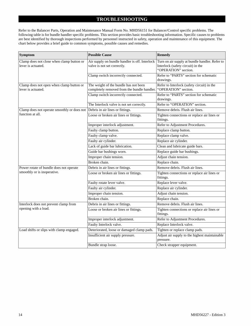
TROUBLESHOOTING
Refer to the Balancer Parts, Operation and Maintenance Manual Form No. MHD56151 for Balancer/Control specific problems. The following table is for bundle handler specific problems. This section provides basic troubleshooting information. Specific causes to problems are best identified by thorough inspections performed by personnel instructed in safety, operation and maintenance of this equipment. The chart below provides a brief guide to common symptoms, possible causes and remedies.
Symptom Possible Cause Remedy
Clamp does not close when clamp button or lever is actuated.
Air supply on bundle handler is off. Interlock valve is not set correctly.
Turn on air supply at bundle handler. Refer to Interlock (safety circuit) in the “OPERATION” section.
Clamp switch incorrectly connected. Refer to “PARTS” section for schematic drawings.
Clamp does not open when clamp button or lever is actuated.
The weight of the bundle has not been completely removed from the bundle handler.
Refer to Interlock (safety circuit) in the “OPERATION” section.
Clamp switch incorrectly connected. Refer to “PARTS” section for schematic drawings.
The Interlock valve is not set correctly. Refer to “OPERATION” section.Clamp does not operate smoothly or does not function at all.
Debris in air lines or fittings. Remove debris. Flush air lines. Loose or broken air lines or fittings. Tighten connections or replace air lines or
fittings.Improper interlock adjustment. Refer to Adjustment Procedures.Faulty clamp button. Replace clamp button.Faulty clamp valve. Replace clamp valve.Faulty air cylinder. Replace air cylinder.Lack of guide bar lubrication. Clean and lubricate guide bars.Guide bar bushings worn. Replace guide bar bushings.Improper chain tension. Adjust chain tension.Broken chain. Replace chain.
Power rotate of bundle does not operate smoothly or is inoperative.
Debris in air lines or fittings. Remove debris. Flush air lines.Loose or broken air lines or fittings. Tighten connections or replace air lines or
fittings.Faulty rotate lever valve. Replace lever valve.Faulty air cylinder. Replace air cylinder.Improper chain tension. Adjust chain tension.Broken chain. Replace chain.
Interlock does not prevent clamp from opening with a load.
Debris in air lines or fittings. Remove debris. Flush air lines.Loose or broken air lines or fittings. Tighten connections or replace air lines or
fittings.Improper interlock adjustment. Refer to Adjustment Procedures.Faulty Interlock valve. Replace Interlock valve.
Load shifts or slips with clamp engaged. Deteriorated, loose or damaged clamp pads. Tighten or replace clamp pads.Insufficient air supply pressure. Adjust air supply to the highest maintainable
pressure.Bundle strap loose. Check strapper equipment.

MHD56227 - Edition 3 15
MAINTENANCE
• Turn off air supply to system and be sure wire rope is slack before attempting any disassembly operations.• Never perform maintenance on the unit while it is supporting a load.• Before performing maintenance, tag controls:
• Only allow personnel trained in safety and maintenance on this unit to perform service.
• Use of replacement parts other than Ingersoll-Rand original parts could result in damage to the unit and void the warranty.
Maintenance Intervals
The Maintenance Interval chart is based on intermittent operation of the bundle handler eight hours each day, five days per week. If bundle handler operation is more than eight hours per day, or in HEAVY or SEVERE environments, more frequent maintenance should be performed. Refer to “Periodic Inspection” in the “INSPECTION” section for additional information.
Adjustments
Refer to “OPERATION” section for all adjustments.
Disassembly
Refer to Dwgs. MHP2181 on page 18 and MHP2210 on page 20.Labeling all air lines with valve port number or location prior to disconnection will ease reassembly of the bundle handler.1. Lower bundle handler to the floor or a suitable work surface.2. Turn off and lock out the system air supply.3. Depress the down lever until all the air has been exhausted
from the balancer and the load cable is slack.4. Remove the load hook from the bundle handler lifting eye.5. Label and disconnect the air lines at the top of the bundle
handler.6. Remove 4 socket head capscrews and lockwashers from top
of bundle handler.
7. Remove bundle handler top cover.8. Remove socket head capscrews from the top front and back
side covers.9. Remove top front and back side covers.10. Ensure all cable ties are removed prior to any component
removal and replaced upon completion of tasks.
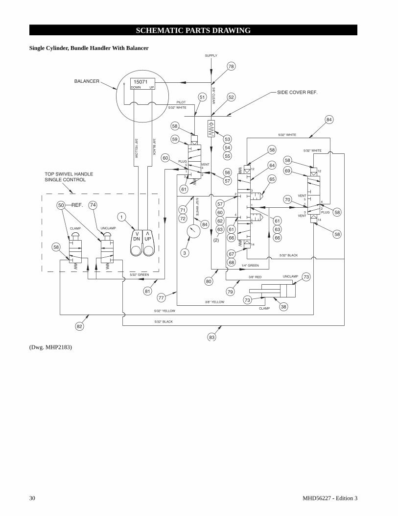
Interlock Valve Removal/Replacement
Refer to Dwg. MHP2183 on page 30.1. Complete the General Disassembly Procedures 1-10.2. Label and disconnect air lines to the valve package.3. Carefully remove the valve package from bundle handler.4. Label and disconnect air fittings connected to the interlock
valve (59).5. Remove interlock valve (59).6. Assemble in reverse order.7. Adjust and test interlock valve. Refer to “OPERATION”
section.
• The interlock valve must be adjusted and tested prior to putting the bundle handler into production.
Clamp and Power Rotate Button Valve Removal/Replacement
1. Complete the General Disassembly Procedures 1-10.2. Label air lines and disconnect from push button valve.3. Remove the setscrew from push button.4. Label and disconnect fittings from push button.5. Remove push button valve.6. Assemble in reverse order.
Cylinder Clamp/Unclamp Valve Removal/Replacement
1. Complete the General Disassembly Procedures 1-10.2. Label air lines and disconnect from cylinder clamp/unclamp
valves.3. Carefully remove the valve package.4. Label and disconnect air fittings from cylinder
clamp/unclamp valves.5. Remove cylinder clamp valve.6. Assemble in reverse order.
• If removing lower air cylinder the bundle handler may be rotated to one side for ease of maintenance.
Air Cylinder Clamp Removal/Replacement
Refer to Dwgs. MHP2210 on page 20 and MHP2181 on page 18.1. Complete the General Disassembly Procedures 1-10.2. Label all air lines to be disconnected.3. Carefully remove valve package.4. Hold air cylinder rod end with proper size wrench. 5. Remove rod end bolt and washer from outside of paddle.6. Remove 4 socket head capscrews and lockwashers from air
cylinder rod end and piston end.7. Remove air cylinder(s).8. Assemble in reverse order.
WARNING - DO NOT OPERATE -EQUIPMENT BEING REPAIRED
INTERVAL MAINTENANCE CHECKStart of each shift
(Operator or Maintenance Personnel)
Make a thorough visual inspection of the bundle handler for damage. Do not operate if damaged.Operate the system through the normal range of movements. System must operate smoothly without sticking, binding or abnormal noises.
3 Months
(Maintenance Personnel)
Inspect interlock. Clean or replace parts as required. Check pivot assembly and guide bars.
Yearly
(Maintenance Personnel)
Check all the supporting members, including the balancer, fasteners, nuts, etc. for indications of damage or wear. Repair or replace as required.
16 MHD56227 - Edition 3
Guide Bar Assembly Removal/Replacement
1. Complete General Disassembly Procedures 1-10.2. Remove bottom support plate.3. Remove air cylinder clamp mount socket head screws from
end cover.4. Remove end cover.5. Remove roll pin from paddle end of guide bar being replaced.6. Slide guide bar assembly out of opposite end cover.7. Assemble in reverse order.8. Lightly lubricate guide bar assembly.
Clamp Chain Removal/Replacement
Refer to Dwg. MHP2210 on page 20.
• When replacing chain ensure the new chain has the same number of links as the chain not being replaced. This will make adjustment of the new chain less difficult.
1. Complete the General Disassembly Procedures 1-10.2. Remove 4 socket head capscrews (60) from side cover of
chain being replaced.3. Loosen tension nut (40) of chain being replaced.4. Slide sprocket assembly to loosen chain.5. Identify and remove the chain master links (27). One master
link is located at the sprocket assembly. The second master link is located on the paddle at the chain attaching bracket (23).
6. Remove chain (26).7. Assemble in reverse order.8. Perform chain tension adjustments.
Chain Tension Adjustments
Refer to Dwg. MHP2210 on page 20.1. Open bundle handler clamp paddles.2. Tighten tension nut (40) until chain has no noticeable slack.3. Check tension rod (68) for bending.4. If tension rod is bending — loosen tension nut until tension
rod becomes straight.5. Cycle clamp/unclamp circuit. Ensure chain does not jump
sprocket. Check for chain chatter and slack when in clamp cycle.
6. If chain jumps sprocket — loosen tension nut and install chain on sprocket. Repeat steps 1-5.
7. If chain chatters or slack is detected — Repeat steps 1-5.8. The chain will be properly adjusted when clamp paddles
move simultaneously with no slack on either chain or bending of tension rod.
Power Rotate Air Cylinder Removal/Replacement
Refer to Dwg. MHP2242 on page 24.1. Complete General Disassembly Procedures steps 1-10.2. Remove paddle end cover (111).3. Label and disconnect air lines from air cylinders (97) to be
removed.4. Loosen locknuts (96). Slide sprocket assembly to loosen
chain.5. Remove socket head capscrews (106) attaching chain to
tension block (105) on cylinder rod end.6. Remove cotter pin (99) from cylinder mount dowel pin (100).7. Remove cylinder mount clevis dowel pin (100).
8. Remove air cylinder (97).9. Remove chain tension block from air cylinder rod end.10. Assemble in reverse order.11. Perform Power Rotate Chain Tension Adjustments.
Power Rotate Chain Removal/Replacement
1. Complete General Disassembly Procedures steps 1-10.2. Remove paddle end cover (111).3. Loosen tension locknut (96) until chain is slack.4. Identify and remove master links (108) of chain.5. Remove chain (89).6. Assemble in reverse order.7. Perform chain tension adjustments.
Power Rotate Chain Tension Adjustment
1. Tighten tension locknut (96) until chain has no slack.2. Cycle power rotate.3. Check for chain clatter and slack during cycle.4. Repeat steps 1-3 until rotating paddle moves smoothly.
Cleaning, Inspection and Repair
Examine disassembled components and fasteners for wear or damage. If worn or damaged, do not reuse. During reassembly all damaged and worn components should be replaced to prevent component failure which may result in injury or property damage.
It is recommended that locknuts be discarded and replaced with new ones after each use.
Use the following procedures to clean, inspect and repair the bundle handler and associated components.
Cleaning
Thoroughly clean all bundle handler components in solvent. The use of a stiff bristle brush will facilitate the removal of accumulated dirt and sediments on the housings. Wipe off each part after cleaning. Remove all old Loctite® residue.
Inspection
All disassembled parts should be inspected to determine their fitness for continued use. Pay particular attention to the following:1. Inspect all threaded items and replace those having damaged
threads.2. Inspect pivot handle. Replace if bent, distorted or worn.3. Inspect air lines for cracks, cuts and leakage. Ensure there are
no pinched air hoses.4. Inspect air fittings for cracks, leakage and security.5. Inspect maneuvering handles for wear and damage.6. Ensure clamp valve functions.7. Ensure bundle handler support swivel assembly rotates
freely.
Repair
Actual repairs are limited to the removal of small burrs and other minor surface imperfections. Use a fine stone or emery cloth for this work.1. Worn or damaged parts must be replaced. Refer to parts
section for specific replacement parts information.

MHD56227 - Edition 3 17
2. Inspect all remaining parts for evidence of wear or damage. Replace or repair any parts which are in questionable condition. The cost of the part is often minor in comparison with the cost of redoing the job.
Assembly
Bundle Handler
Refer to Dwgs. MHP2181 on page 18 and MHP2210 on page 20.1. Gather air lines together and install cable ties to ensure lines
do not rub, bind or get pinched during bundle handler operation.
2. Install top front and back side covers with capscrews.3. Install bundle handler top cover with lockwashers and
capscrews.4. Connect air lines to the top of the bundle handler as labeled
during disassembly.5. Attach the Balancer load hook to the bundle handler lifting
eye.6. Turn on the system air supply.7. Check all bundle handler functions to ensure correct
operation.
Testing
Prior to testing bundle handlers, various control valves must be adjusted. Refer to ‘Operation Adjustments’on page 10 for these adjustments.
Bundle Handler
With NO load: 1. Actuate ‘UP’ lever. bundle handler should rise smoothly.
Actuate ‘DOWN’ lever. bundle handler should lower smoothly. If movement direction does not match levers, correct before placing bundle handler in service.
2. Actuate clamp control.3. Actuate rotate control if equipped.
With Load:1. Place a test load equal to 100% of capacity.2. Actuate ‘UP’ lever. bundle handler should rise smoothly.
Actuate ‘DOWN’ lever. Bundle handler should lower smoothly. If movement direction does not match levers, correct before placing bundle handler in service.
3. Actuate clamp control.
Interlock Valve
• Interlock valve will not allow clamp control to release while bundle handler is supporting a load.
1. To test, engage nose assembly in a load and lift 2-3 inches (51-76 mm) off the floor. Actuate clamp control to the unclamp position. Load should remain secured to bundle handler. For adjustments refer to ‘Operation Adjustments’on page 10.

18 MHD56227 - Edition 3
BUNDLE HANDLER ASSEMBLY PARTS DRAWING
Single Cylinder - 24 to 48 inch (610 to 1219 mm) bundles
(Dwg. MHP2181)
MHD56227 - Edition 3 19
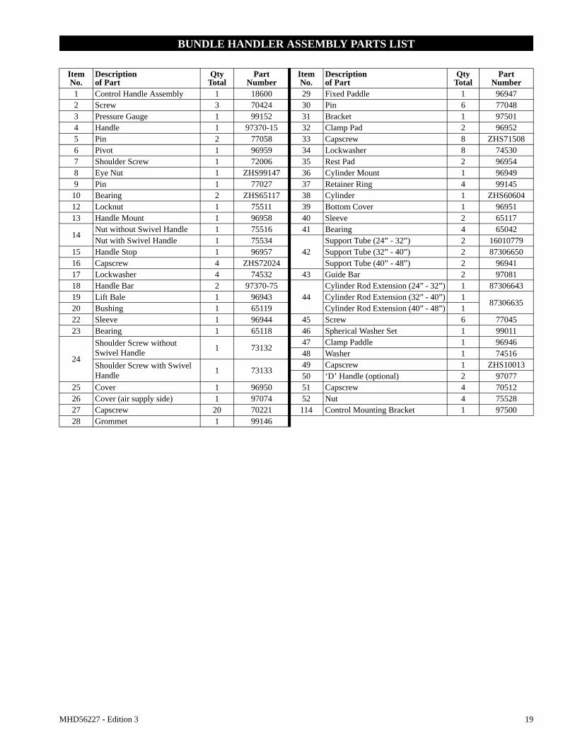
BUNDLE HANDLER ASSEMBLY PARTS LIST
Item No.
Descriptionof Part
QtyTotal
Part Number
Item No.
Descriptionof Part
QtyTotal
Part Number
1 Control Handle Assembly 1 18600 29 Fixed Paddle 1 969472 Screw 3 70424 30 Pin 6 770483 Pressure Gauge 1 99152 31 Bracket 1 975014 Handle 1 97370-15 32 Clamp Pad 2 969525 Pin 2 77058 33 Capscrew 8 ZHS715086 Pivot 1 96959 34 Lockwasher 8 745307 Shoulder Screw 1 72006 35 Rest Pad 2 969548 Eye Nut 1 ZHS99147 36 Cylinder Mount 1 969499 Pin 1 77027 37 Retainer Ring 4 99145
10 Bearing 2 ZHS65117 38 Cylinder 1 ZHS6060412 Locknut 1 75511 39 Bottom Cover 1 9695113 Handle Mount 1 96958 40 Sleeve 2 65117
14Nut without Swivel Handle 1 75516 41 Bearing 4 65042Nut with Swivel Handle 1 75534
42Support Tube (24” - 32”) 2 16010779
15 Handle Stop 1 96957 Support Tube (32” - 40”) 2 8730665016 Capscrew 4 ZHS72024 Support Tube (40” - 48”) 2 9694117 Lockwasher 4 74532 43 Guide Bar 2 9708118 Handle Bar 2 97370-75
44Cylinder Rod Extension (24” - 32”) 1 87306643
19 Lift Bale 1 96943 Cylinder Rod Extension (32” - 40”) 187306635
20 Bushing 1 65119 Cylinder Rod Extension (40” - 48”) 122 Sleeve 1 96944 45 Screw 6 7704523 Bearing 1 65118 46 Spherical Washer Set 1 99011
24
Shoulder Screw without Swivel Handle 1 73132
47 Clamp Paddle 1 9694648 Washer 1 74516
Shoulder Screw with Swivel Handle 1 73133
49 Capscrew 1 ZHS1001350 ‘D’ Handle (optional) 2 97077
25 Cover 1 96950 51 Capscrew 4 7051226 Cover (air supply side) 1 97074 52 Nut 4 7552827 Capscrew 20 70221 114 Control Mounting Bracket 1 9750028 Grommet 1 99146
20 MHD56227 - Edition 3
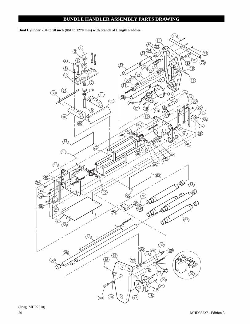
BUNDLE HANDLER ASSEMBLY PARTS DRAWING
Dual Cylinder - 34 to 50 inch (864 to 1270 mm) with Standard Length Paddles
(Dwg. MHP2210)
6054
6
5
4 3
21
7
811
55
28
31
10
60
9
28
2021
30
3229
2226
2524
14
23
15
12
71
1316
15
19
39
18
1734
36
3559
37
3841
40
48
424946
4544
43
53
74
73
65
66
47
4048
52
56
60
63
4060
4034
36
59
64
5758
68
6715
69 13 1718
1921
20
1523
27
26
3222
2425
27
50
70
76
33
58
33
28
50
58
MHD56227 - Edition 3 21
BUNDLE HANDLER ASSEMBLY PARTS LIST
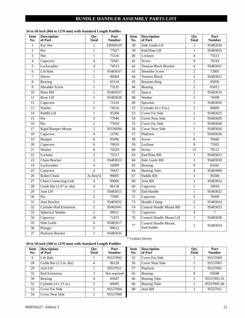
34 to 50 inch (864 to 1270 mm) with Standard Length PaddlesItem No.
Descriptionof Part
QtyTotal
Part Number
Item No.
Descriptionof Part
QtyTotal
Part Number
1 Eye Nut 1 ZHS99147 38 Side Guide LH 1 954830182 Pin 1 77027 39 End Plate LH 1 954830163 Nut 1 75516 40 Locknut 4 755114 Capscrew 4 72047 41 Screw 8 702195 Lockwasher 4 74513 42 Tension Block Bracket 4 954830316 Lift Bale 1 95483037 43 Shoulder Screw 2 720057 Sleeve 1 96944 44 Tension Block 2 954830128 Bearing 1 65118 45 Retainer Ring 2 650509 Shoulder Screw 1 73132 46 Bearing 2 65012
10 Riser RH 1 95483027 47 Spacer 2 9548301911 Riser LH 1 95483028 48 Washer 2 7450812 Capscrew 1 73143 49 Sprocket 2 9548302013 Washer 2 74516 52 Cylinder (4 x 8 in.) 2 6060014 Paddle LH 1 95508 53 Cover Far Side 1 9548302515 Pin 4 77048 54 Cover Near Side 1 9548302916 Pin 2 77054 55 Cover Far Side 1 9548303017 Rigid Bumper Mount 2 95536094 56 Cover Near Side 1 9548301018 Capscrew 4 15782 57 Platform 1 9548303619 Bumper 6 93096 58 Screw 8 7044620 Capscrew 6 70919 59 Locknut 8 7550321 Washer 6 74529 60 Screw 12 7011222 Locknut 2 75517 63 End Plate RH 1 9548301523 Chain Bracket 2 95483013 64 Side Guide RH 1 9548301824 Lockwasher 4 16099 65 Bearing 8 6504225 Capscrew 4 70437 66 Bearing Tube 4 9548300926 Roller Chain As Req’d 99005 67 Paddle RH 1 9550827 Chain Connecting Link 4 99006 68 Arm RH 1 9548301428 Guide Bar (1.67 in. dia) 4 96138 69 Capscrew 1 1001929 Arm LH 1 95483011 70 End Handle 1 9548302230 Pin 2 77005 71 Capscrew 2 7043031 Arm Bracket 2 95483032 73 Handle Clamp 2 9548302432 Cylinder Rod Extension 2 95483041 74 Control Handle Mount RH 1 9548302333 Spherical Washer 2 99011 75 Capscrew 4 *34 Capscrew 16 71473 76 Control Handle Mount LH 1 9548303835 Side Guide 4 95483017
77 Control Handle Mount,End Paddle 2 95483034
36 Plunger 2 9901237 Platform Bracket 2 95483035
* Contact factory20 to 50 inch (508 to 1270 mm) with Standard Length Paddles
Item No.
Descriptionof Part
QtyTotal
Part Number
Item No.
Descriptionof Part
QtyTotal
Part Number
6 Lift Bale 1 95537002 55 Cover Far Side 1 9553700928 Guide Bar (1.5 in. dia) 4 96128 56 Cover Near Side 1 9553700329 Arm LH 1 95537011 57 Platform 1 9553700132 Rod Extension 2 Not required 65 Bearing 8 6504850 Bearing 4 65047 66 Bearing Tube 3 95537005-3552 Cylinder (4 x 15 in.) 2 60605 66 Bearing Tube 1 95537005-4053 Cover Far Side 1 95537004 68 Arm RH 1 9553701154 Cover Near Side 1 95537008

22 MHD56227 - Edition 3
BUNDLE HANDLER ASSEMBLY PARTS DRAWING
Dual Cylinder34 to 50 in. (864 to 1270 mm) with 4 inch Extended Length Paddles
(Dwg. MHP2401)
28
25
2423
1415
12
13
16
15
26
32
29
30
31
28
21
20
17
19 18
68
2524
2267
15
13
69
1523
27
26
2021
19
1817
22
33
33

MHD56227 - Edition 3 23
BUNDLE HANDLER ASSEMBLY PARTS LIST
Item No.
Descriptionof Part
QtyTotal
Part Number
Item No.
Descriptionof Part
QtyTotal
Part Number
1 Eye Nut 1 ZHS99147 38 Side Guide LH 1 954830392 Pin 1 77027 39 End Plate LH 1 954830163 Nut 1 75516 40 Locknut 4 755114 Capscrew 4 72047 41 Screw 8 702195 Lockwasher 4 74513 42 Tension Block Bracket 4 954830316 Lift Bale 1 95483037 43 Shoulder Screw 2 720057 Sleeve 1 96944 44 Tension Block 2 954830128 Bearing 1 65118 45 Retainer Ring 2 650509 Shoulder Screw 1 73132 46 Bearing 2 65012
10 Riser RH 1 95483027 47 Spacer 2 9548301911 Riser LH 1 95483028 48 Washer 2 7450812 Capscrew 1 73143 49 Sprocket 2 9548302013 Washer 4 74516 52 Cylinder (4 x 15 in.) 2 6060514 Paddle LH 1 97523 53 Cover Far Side 1 9548302515 Pin 4 77048 54 Cover Near Side 1 9548302916 Pin 2 77054 55 Cover Far Side 1 9548303017 Rigid Bumper Mount 2 95536094 56 Cover Near Side 1 9548301018 Capscrew 4 15782 57 Platform 1 9548303619 Bumper 6 93096 58 Screw 8 7044620 Capscrew 6 70919 59 Locknut 8 7550321 Washer 6 74529 60 Screw 12 7011222 Locknut 2 75517 63 End Plate RH 1 9548301523 Chain Bracket 2 95483013 64 Side Guide RH 1 9548304024 Lockwasher 4 74506 65 Bearing 8 6504225 Capscrew 4 70437 66 Bearing Tube 4 9548300926 Roller Chain As Req’d 99005 67 Paddle RH 1 9550827 Chain Connecting Link 4 99006 68 Arm RH 1 9548301428 Guide Bar 4 96138 69 Capscrew 1 1001929 Arm LH 1 95483011 70 End Handle 1 9548302230 Pin 2 77005 71 Capscrew 2 7043031 Arm Bracket 2 95483032 73 Handle Clamp 2 9548302432 Cylinder Rod Extension 2 95483041 74 Control Handle Mount RH 1 9548302333 Spherical Washer Set 2 99011 75 Capscrew 4 *34 Capscrew 16 71473 76 Control Handle Mount LH 1 9548303835 Side Guide 4 95483017
77 Control Handle Mount,End Paddle 2 95483034
36 Plunger 2 9901237 Platform Bracket 2 95483035
* Contact factoryRefer to Dwg. MHP2210 on page 20 for parts listed on this page that are not shown on Dwg. MHP2401.
24 MHD56227 - Edition 3
POWER ROTATE PADDLE ASSEMBLY PARTS DRAWING
Standard Length Paddles
(Dwg. MHP2242)
105
108 107106
104
89103
94
90
101 92
91
8988
87 112
86
19 2120
83
84
110
109
111
100
99
9895
96
2021
19
17
84
8382
81
8014
93
85
97
MHD56227 - Edition 3 25
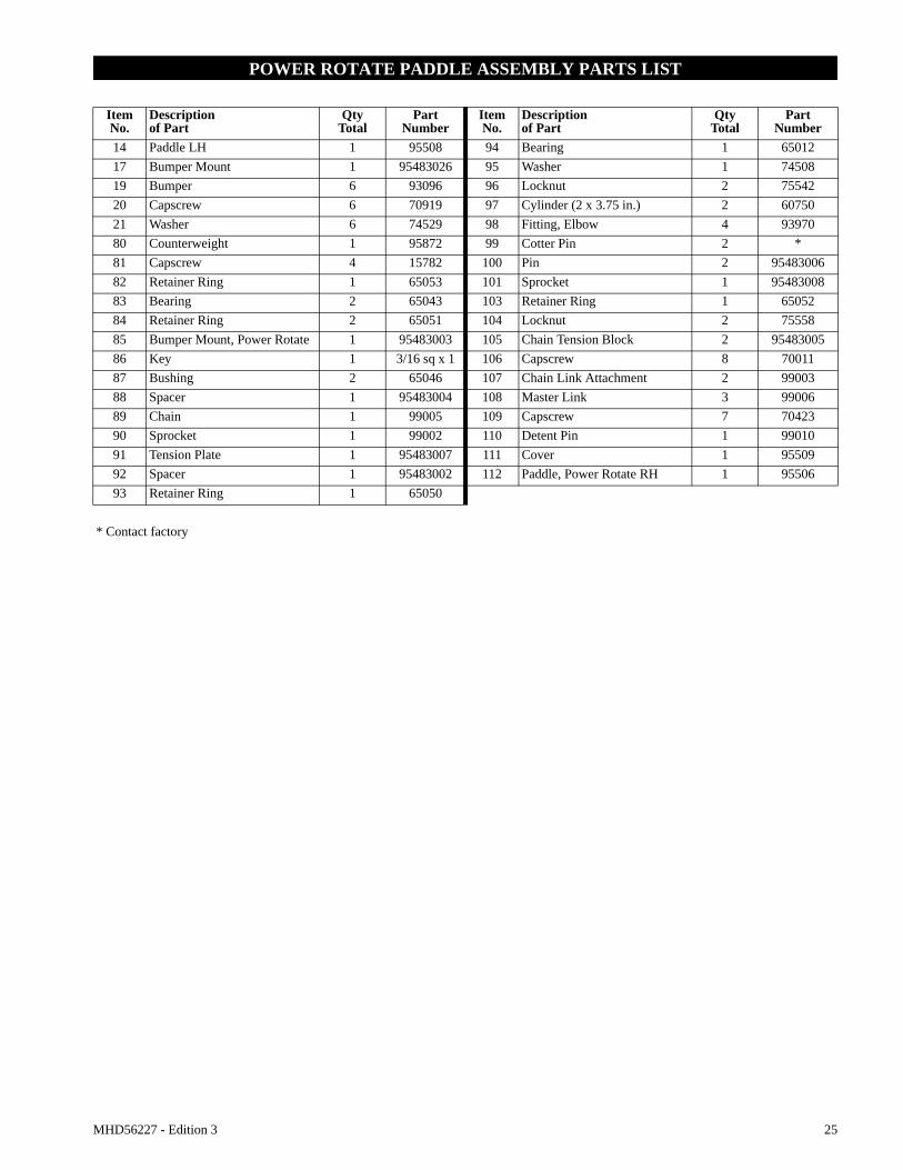
POWER ROTATE PADDLE ASSEMBLY PARTS LIST
Item No.
Descriptionof Part
QtyTotal
Part Number
Item No.
Descriptionof Part
QtyTotal
Part Number
14 Paddle LH 1 95508 94 Bearing 1 6501217 Bumper Mount 1 95483026 95 Washer 1 7450819 Bumper 6 93096 96 Locknut 2 7554220 Capscrew 6 70919 97 Cylinder (2 x 3.75 in.) 2 6075021 Washer 6 74529 98 Fitting, Elbow 4 9397080 Counterweight 1 95872 99 Cotter Pin 2 *81 Capscrew 4 15782 100 Pin 2 9548300682 Retainer Ring 1 65053 101 Sprocket 1 9548300883 Bearing 2 65043 103 Retainer Ring 1 6505284 Retainer Ring 2 65051 104 Locknut 2 7555885 Bumper Mount, Power Rotate 1 95483003 105 Chain Tension Block 2 9548300586 Key 1 3/16 sq x 1 106 Capscrew 8 7001187 Bushing 2 65046 107 Chain Link Attachment 2 9900388 Spacer 1 95483004 108 Master Link 3 9900689 Chain 1 99005 109 Capscrew 7 7042390 Sprocket 1 99002 110 Detent Pin 1 9901091 Tension Plate 1 95483007 111 Cover 1 9550992 Spacer 1 95483002 112 Paddle, Power Rotate RH 1 9550693 Retainer Ring 1 65050
* Contact factory

26 MHD56227 - Edition 3
POWER ROTATE PADDLE ASSEMBLY PARTS DRAWING
4 inch (102 mm) Extended Paddles
(Dwg. MHP2404)
1480
81
2021
19
17
84
83
82
105
108 107106
89104
2021
19
86
858483
101
103
90 8988
87 112
93
92
91
111
102
99100
113
98
96
95
94
109

MHD56227 - Edition 3 27
POWER ROTATE PADDLE ASSEMBLY PARTS LIST
Item No.
Descriptionof Part
QtyTotal
Part Number
Item No.
Descriptionof Part
QtyTotal
Part Number
14 Paddle LH 1 97523 94 Bearing 1 6501217 Bumper Mount 1 95483-94 95 Washer 1 7450819 Bumper 6 93096 96 Locknut 2 7554220 Capscrew 6 70919 97 Cylinder (2 x 3.75) 2 6075021 Washer 6 74529 98 Fitting, Elbow 4 9397080 Counterweight 1 95872 99 Cotter Pin 2 *81 Capscrew 4 15782 100 Pin 2 95483-882 Retainer Ring 1 65053 101 Sprocket 1 9900183 Bearing 2 65043 102 Clevis 2 9616884 Retainer Ring 2 65051 103 Retainer Ring 1 6505285 Bumper Mount, Power Rotate 1 95483-4 104 Locknut 2 6075186 Key 1 3/16 sq x 1 in. 105 Chain Tension Block 2 95483-587 Bushing 2 65046 106 Capscrew 8 7001188 Spacer 1 95483-6 107 Chain Link Attachment 2 9900389 Chain 1 99005 108 Master Link 3 9900690 Sprocket 1 99002 109 Capscrew 7 7040291 Tension Plate 1 95483-7 111 Cover 1 9752492 Spacer 1 95483-3 112 Paddle, Power Rotate RH 1 9752193 Retainer Ring 1 65050 113 Capscrew 2 71445
* Contact factory

28 MHD56227 - Edition 3
SELF RETRACTING LEVELING PAD ASSEMBLY PARTS DRAWING
For 34 to 50 inch (864 to 1270 mm) bundles
(Dwg. MHP2285)
58
57
40
47
4645
4443
42
84
83 82
34
92
90
85
86
87
36
89
88
59
80
81
92
5838
3492
92
86
83
84
LH
RH
92
94
93
41
MHD56227 - Edition 3 29
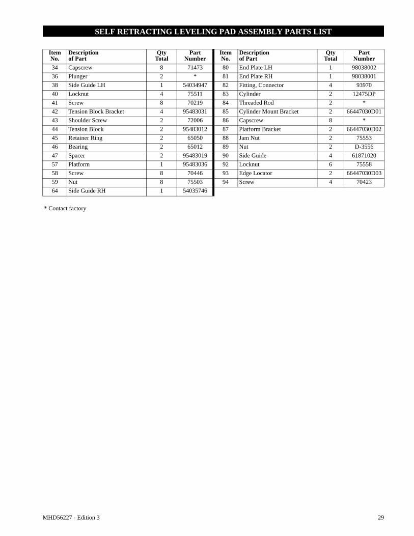
SELF RETRACTING LEVELING PAD ASSEMBLY PARTS LIST
Item No.
Descriptionof Part
QtyTotal
Part Number
Item No.
Descriptionof Part
QtyTotal
Part Number
34 Capscrew 8 71473 80 End Plate LH 1 9803800236 Plunger 2 * 81 End Plate RH 1 9803800138 Side Guide LH 1 54034947 82 Fitting, Connector 4 9397040 Locknut 4 75511 83 Cylinder 2 12475DP41 Screw 8 70219 84 Threaded Rod 2 *42 Tension Block Bracket 4 95483031 85 Cylinder Mount Bracket 2 66447030D0143 Shoulder Screw 2 72006 86 Capscrew 8 *44 Tension Block 2 95483012 87 Platform Bracket 2 66447030D0245 Retainer Ring 2 65050 88 Jam Nut 2 7555346 Bearing 2 65012 89 Nut 2 D-355647 Spacer 2 95483019 90 Side Guide 4 6187102057 Platform 1 95483036 92 Locknut 6 7555858 Screw 8 70446 93 Edge Locator 2 66447030D0359 Nut 8 75503 94 Screw 4 7042364 Side Guide RH 1 54035746
* Contact factory
30 MHD56227 - Edition 3
SCHEMATIC PARTS DRAWING
Single Cylinder, Bundle Handler With Balancer
(Dwg. MHP2183)
15071
REF. 74
58
1
50
72
71
3
68
67
61
(2)
63
62
61
66
60
57
38
73
73
81
80
79
83
82
77
66
63
61
70
58
58
60
59
58
55
57
56
54
53
84
51 52
78
84
SIDE COVER REF.
65
64
58
69
58
CLAMP UNCLAMP
1/4" GREEN
5/32" BLACK
5/32" YELLOW
5/32" GREEN
UPDN
V
V
3/8" YELLOW
5/32" WH
ITE
4
2
CLAMP
VENT
VENT
14
3/8" RED UNCLAMP
5/32" BLACK
5
3
1
14
5
1
3 PLUG
4
2
PLUG
5/32" WHITE
BALANCER
TOP SWIVEL HANDLESINGLE CONTROL
PILOT
3/8" YE
LLOW
3/8" BLA
CK
UPDOWN
1
3
5 VENT
2
4
3/8" CLE
AR
SUPPLY
12
5/32" WHITE
12
5/32" WHITE
MHD56227 - Edition 3 31
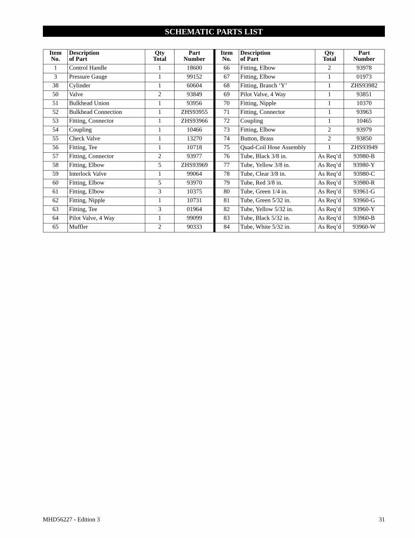
SCHEMATIC PARTS LIST
Item No.
Descriptionof Part
QtyTotal
PartNumber
Item No.
Descriptionof Part
QtyTotal
PartNumber
1 Control Handle 1 18600 66 Fitting, Elbow 2 939783 Pressure Gauge 1 99152 67 Fitting, Elbow 1 01973
38 Cylinder 1 60604 68 Fitting, Branch ‘Y’ 1 ZHS9398250 Valve 2 93849 69 Pilot Valve, 4 Way 1 9385151 Bulkhead Union 1 93956 70 Fitting, Nipple 1 1037052 Bulkhead Connection 1 ZHS93955 71 Fitting, Connector 1 9396353 Fitting, Connector 1 ZHS93966 72 Coupling 1 1046554 Coupling 1 10466 73 Fitting, Elbow 2 9397955 Check Valve 1 13270 74 Button, Brass 2 9385056 Fitting, Tee 1 10718 75 Quad-Coil Hose Assembly 1 ZHS9394957 Fitting, Connector 2 93977 76 Tube, Black 3/8 in. As Req’d 93980-B58 Fitting, Elbow 5 ZHS93969 77 Tube, Yellow 3/8 in. As Req’d 93980-Y59 Interlock Valve 1 99064 78 Tube, Clear 3/8 in. As Req’d 93980-C60 Fitting, Elbow 5 93970 79 Tube, Red 3/8 in. As Req’d 93980-R61 Fitting, Elbow 3 10375 80 Tube, Green 1/4 in. As Req’d 93961-G62 Fitting, Nipple 1 10731 81 Tube, Green 5/32 in. As Req’d 93960-G63 Fitting, Tee 3 01964 82 Tube, Yellow 5/32 in. As Req’d 93960-Y64 Pilot Valve, 4 Way 1 99099 83 Tube, Black 5/32 in. As Req’d 93960-B65 Muffler 2 90333 84 Tube, White 5/32 in. As Req’d 93960-W

32 MHD56227 - Edition 3
SCHEMATIC PARTS DRAWING
Dual Controls, Power Rotate Bundle Handler With Balancer
(Dwg. MHP2217)
UnclampClamp
UnclampClamp
1/2" Black
1/2" Clear
15094
Dow
n / U
p15071
1/2" Yellow
Vent4 521
3
Supply
3/8
" Yello
w
3/8
" B
lack
14
1
3
4
2
32
14
5
12
4
12
Clamp
85 86
1/4" Black
5
Up Down
5
13
Up
Down
87
61
51
64
58
51
95
60
68
61
68
96
67
58 97
6669
58 57
63
58
58
97
9662
61
67 58
65
73
65
73
59
56
9998
9091 58 100 9351 51
92
90
9457 57
53 8954 88
9553
Clamp
6654 86
154
1
5554 66
1
2
4
7677
MHD56227 - Edition 3 33
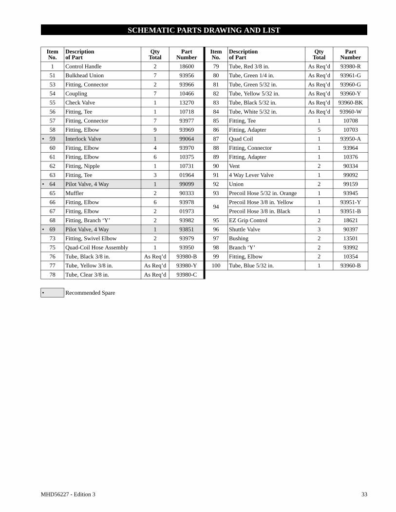
SCHEMATIC PARTS DRAWING AND LIST
Item No.
Descriptionof Part
QtyTotal
PartNumber
Item No.
Descriptionof Part
QtyTotal
PartNumber
1 Control Handle 2 18600 79 Tube, Red 3/8 in. As Req’d 93980-R51 Bulkhead Union 7 93956 80 Tube, Green 1/4 in. As Req’d 93961-G53 Fitting, Connector 2 93966 81 Tube, Green 5/32 in. As Req’d 93960-G54 Coupling 7 10466 82 Tube, Yellow 5/32 in. As Req’d 93960-Y55 Check Valve 1 13270 83 Tube, Black 5/32 in. As Req’d 93960-BK56 Fitting, Tee 1 10718 84 Tube, White 5/32 in. As Req’d 93960-W57 Fitting, Connector 7 93977 85 Fitting, Tee 1 1070858 Fitting, Elbow 9 93969 86 Fitting, Adapter 5 10703
• 59 Interlock Valve 1 99064 87 Quad Coil 1 93950-A60 Fitting, Elbow 4 93970 88 Fitting, Connector 1 9396461 Fitting, Elbow 6 10375 89 Fitting, Adapter 1 1037662 Fitting, Nipple 1 10731 90 Vent 2 9033463 Fitting, Tee 3 01964 91 4 Way Lever Valve 1 99092
• 64 Pilot Valve, 4 Way 1 99099 92 Union 2 9915965 Muffler 2 90333 93 Precoil Hose 5/32 in. Orange 1 9394566 Fitting, Elbow 6 93978
94Precoil Hose 3/8 in. Yellow 1 93951-Y
67 Fitting, Elbow 2 01973 Precoil Hose 3/8 in. Black 1 93951-B68 Fitting, Branch ‘Y’ 2 93982 95 EZ Grip Control 2 18621
• 69 Pilot Valve, 4 Way 1 93851 96 Shuttle Valve 3 9039773 Fitting, Swivel Elbow 2 93979 97 Bushing 2 1350175 Quad-Coil Hose Assembly 1 93950 98 Branch ‘Y’ 2 9399276 Tube, Black 3/8 in. As Req’d 93980-B 99 Fitting, Elbow 2 1035477 Tube, Yellow 3/8 in. As Req’d 93980-Y 100 Tube, Blue 5/32 in. 1 93960-B78 Tube, Clear 3/8 in. As Req’d 93980-C
• Recommended Spare

34 MHD56227 - Edition 3
PARTS ORDERING INFORMATION
Bundle handlers are designed and constructed to provide long, trouble-free service. In time it may become necessary to order and install new parts to replace those that have been subjected to wear.
The use of replacement parts other than Ingersoll-Rand may result in decreased performance, and may, at the company’s option invalidate the warranty.
For prompt service and genuine Ingersoll-Rand parts, provide your nearest Distributor with the following:1. Complete Model description. 2. Part number and part description as shown in this manual.3. Quantity required.
For your convenience and future reference it is recommended that the following information be recorded:
Model Description____________________________________
Date Purchased ______________________________________
Serial Number _______________________________________
Return Goods Policy
Ingersoll-Rand will not accept any returned goods for warranty or service work unless prior arrangements have been made and written authorization has been provided from the location where the goods were purchased.
• Continuing improvement and advancement of design may produce changes to this unit which are not included in this manual. Manuals are periodically revised to incorporate changes. Always check the manual edition number on the front cover for the latest issue.
Disposal
When the life of the unit has expired, it is recommended that the air motor be disassembled, degreased and parts separated as to materials so that they may be recycled.
For additional information contact:Ingersoll-Rand Handling Systems1872 Enterprise DriveRochester Hills, MI 48309Phone: (248) 293-5700Fax: (248) 293-5800
or
Ingersoll-RandDouai Operations529, Avenue Roger Salengro59450 Sin Le Noble, FrancePhone: (33) 3-27-93-08-08Fax: (33) 3-27-93-08-08
For additional information on the following products order the publication by the referenced Part/Document Number listed:Publication Part/Document Number Publication Part/Document NumberZ-Balancer MHD56151 Z-Rail System MHD56159
Manipulator Arm MHD56162 Valu-Trak Rail System MHD56161
MHD56227 - Edition 3 35
LIMITED WARRANTY
Ingersoll-Rand Company (I-R) warrants to the original user its Products to be free of defects in material and workmanship for a period of one year from the date of purchase. I-R will repair, without cost, any Product found to be defective, including parts and labor charges, or at its option, will replace such Products or refund the purchase price less a reasonable allowance for depreciation, in exchange for the Product. Repairs or replacements are warranted for the remainder of the original warranty period.
If any Product proves defective within its original one year warranty period, it should be returned to any Authorized I-R Material Handling Service Distributor, transportation prepaid with proof of purchase or warranty card.
This warranty does not apply to Products which I-R has determined to have been misused or abused, improperly maintained by the user, or where the malfunction or defect can be attributed to the use of non-genuine I-R parts.
I-R makes no other warranty, and all implied warranties including any warranty of merchantability or fitness for a particular purpose are limited to the duration of the expressed warranty period as set forth above. I-R’s maximum liability is limited to the purchase price of the Product and in no event shall I-R be liable for any consequential, indirect, incidental, or special damages of any nature rising from the sale or use of the Product, whether based on contract, tort, or otherwise.
Note: Some states do not allow limitations on incidental or consequential damages or how long an implied warranty lasts so that the above limitations may not apply to you.
This warranty gives you specific legal rights and you may also have other rights which may vary from state to state.
IMPORTANT NOTICE
It is our policy to promote safe delivery of all orders.
This shipment has been thoroughly checked, packed and inspected before leaving our plant and receipt for it in good condition has been received from the carrier. Any loss or damage which occurs to this shipment while en route is not due to any action or conduct of the manufacturer.
Visible Loss or DamageIf any of the goods called for on the bill of lading or express receipt are damaged or the quantity is short, do not accept them until the freight or express agent makes an appropriate notation on your freight bill or express receipt.
Concealed Loss or DamageWhen a shipment has been delivered to you in apparent good condition, but upon opening the crate or container, loss or damage has taken place while in transit, notify the carrier’s agent immediately.
Damage ClaimsYou must file claims for damage with the carrier. It is the transportation company’s responsibility to reimburse you for repair or replacement of goods damaged in shipment. Claims for loss or damage in shipment must not be deducted from the Ingersoll-Rand invoice, nor should payment of Ingersoll-Rand invoice be withheld awaiting adjustment of such claims as the carrier guarantees safe delivery.
You may return products damaged in shipment to us for repair, which services will be for your account and form your basis for claim against the carrier.

www.ingersollrandproducts.com R