pascal series 5 to 21 m /h i, sd, c1, c2 series
TRANSCRIPT

PASCAL Series5 to 21 m3/h
I, SD, C1, C2 Series
ROTARY VANE PUMPS
User’s Manual
Rea
lizat
ion
/Pu
blic
atio
n: A
lcat
el V
acu
um
Tec
hn
olo
gy
Fran
ce -
Pri
nti
ng
: Pla
nch
er S
A -
Use
r’s
Man
ual
- E
d.0
7 -
04/2
008
- Pa
rt n
um
ber
: 103
275

Alcatel Vacuum Technology, as part of the Alcatel-Lucent Group, has been supplying vacuum pumps, helium and hydrogen leak detection systems, plasma sensors, vacuum measurement for several years.
Thanks to its complete range of products, the company has become an essential player in multiple applications : instrumentation, Research & Developement, industry and semiconductors.
Alcatel Vacuum Technology has launched Adixen, its new brand name, in recognition of the company’s international standing in vacuum position.
With both ISO 9001 and 14001 certifications, the French company is an acknowlegded expert in service and support, and Adixen products have the highest quality and environmental standards.
With 45 years of experience, AVT today has a worldwide presence, through its international network that includes a whole host of experienced subsidiaries, distributors and agents.
The first step was the founding of Alcatel Vacuum Products (Hingham- MA) in the United States, thirty years ago, reinforced today by 2 others US subsidiaries in Fremont (CA) and Tempe (AZ).
In Europe, AVTF-France headquarters and its subsidiaries, Alcatel Hochvakuumtechnik (Germany), Alcatel Vacuum Technology UK (Scotland), Alcatel Vacuum Technology Benelux (Netherlands), Alcatel Vacuum Systems (Italy) and more recently Adixen Sensistor AB in Sweden (in 2007) form the foundation for the European partner network.
In Asia, our presence started in 1993 with Alcatel Vacuum Technology (Japan), and has been strengthened with Alcatel Vacuum Technology Korea (in 1995), Alcatel Vacuum Technology Taiwan (in 2001), Alcatel Vacuum Technology Singapore, Alcatel Vacuum Technology Shanghai (China) (in 2004)
This organization is rounded off by more than 40 represensatives based in a variety of continents.
Thus, whatever the circumstances, the users of Adixen products can always rely on quick support of our specialists in Vacuum Technology.
Gb
028
34 -
Edi
tion
04 -
Aug
200
7

53
Rotary vane pumps
Welcome
Dear customer,
You have just bought an Adixen rotary vane pump. We would like to thank you and are proud to count you among our customers.
This product is a result of experience acquired over many years by Alcatel Vacuum Technology in the design of rotary vane pumps.
APPLICATIONS:
• RESEARCH AND DEVELOPMENT
Physics and chemistry laboratories, etc.
• INDUSTRY
Foodstuffs (freeze-drying), Pharmaceuticals, Electronic tube manufacture, Metallurgy, Drying systems, Refrigeration systems, Chemical industry, etc.
• INSTRUMENTATION
Mass spectrometetry, Centrifuges, Electronic microscopes, Leak detection systems, etc.
• VARIOUS SEMICONDUCTOR PROCESSES
EN – 1
We suggest that you read this manual, particularly the chapter on installation and operation, before you start to use this pump so that you can obtain optimum levels of performance and complete satisfaction from this equipment.

EN – 2
Copyright/Intellectual property:The use of Adixen products are subject to copyright and intellectual property rights in force in any jurisdiction. All rights reserved. including copying this document in whole or any part without prior written authorization from Alcatel Vacuum Technology France.Specifications and information are subject to change without notice by Alcatel Vacuum Technology France.
This product complies with the requirements of European Directives. listed in the Declaration of Conformity contained in page 55 of this manual. These Directives are amended by Directive 93/68/E.E.C (E.C. Marking).
Indicates a potentially hazardous situation which, if not avoided, could result in moderate or minor injury. It may also be used to alert against unsafe practices.
Indicates a potentially hazardous situation which, if not avoided, could result in property damage.
Indicates an imminently hazardous situation that, if not avoided, will result in death or severe injury (extreme situations).
Indicates a potentially hazardous situation which, if not avoided, could result in death or severe injury.

EN – 3
Contents
The PASCAL series 5 to 21 m3/hPresentation of the product range ............................................................. 4Operating principle of a rotary vane pump ............................................... 6Technical characteristics ............................................................................. 9Pump dimensions ................................................................................... 12Accessories .............................................................................................. 13
Installation and connectionsSafety instructions ................................................................................... 15Table of recommended oils ...................................................................... 17Filling with oil .......................................................................................... 18Mechanical connections .......................................................................... 20Electrical connections .............................................................................. 22Motor protection ..................................................................................... 23
OperationPrecautions ............................................................................................. 25Operating temperature ........................................................................... 25Before starting up the pump ................................................................... 25Start-up ................................................................................................... 26Operation of gas ballast ........................................................................... 27Particular uses .......................................................................................... 29Oxygen pumping ..................................................................................... 31High pressure pumping and cycling ......................................................... 32
MaintenancePrecautions .............................................................................................. 33Troubleshooting and corrective actions .................................................... 34Maintenance frequency ........................................................................... 37Draining the oil ........................................................................................ 37Flushing the pump ................................................................................... 38Change of type of oil ............................................................................... 38Replacement of front shaft seal ............................................................... 39Tools and consumable products ............................................................... 40Disassembling the pump .......................................................................... 42Cleaning components .............................................................................. 45Replacement of all shaft seals .................................................................. 46Reassembling the pump ........................................................................... 47
Safety questionnaire .......................................................................... 53
Declaration of Conformity ................................................................. 55
NomenclatureSpare parts lists ....................................................................................N – 1
Intr
od
uct
ion
Sta
rt-u
pO
pera
tio
nM
ain
ten
an
ceN
om
en
clatu
reEN

EN – 4
Presentation of the product range
A wide rangeSpecific solutions adapted to
various applications
SD series
Oil seal rotary vane pumps are used in all vacuum technology applications.
They can be used on their own to achieve a maximum vacuum of 10-3 Torr (10-3 mbar). or in pumping assemblies. e.g. at the exhaust of a diffusion pump or turbomolecular pump.
Standard pumps for several purposes (non-corrosive applications).Manufacture of light bulbs. production of TV tubes. manufacture of electronic tubes. metallurgy. centrifuges. etc.
Pumps designed to meet the requirements of analytical instrumentation and R&D.Mass spectrometer. electronic microscopes. GC/MS. LC/MS. gas analyzers. leak detectors. sterilizers. etc.
Pumps suited to the pumping of corrosive gases.R&D. laboratories. freeze-drying. pumping of solvents. etc.
Pumps with increased resistance to meet the requirements of the more aggressive processes of the semiconductor industry.Ion implantation. sputtering. etc.
Sealed pumps offering maximum tightness.Pumping of pure or precious gases.
Nom. fl. rate m3/h 5 10 15 21
I series 2 stages 2005I 2010I 2015I 2021I
SD series1 stage 1005SD 1010SD* 1015SD 1021SD*
2 stages 2005SD 2010SD 2015SD 2021SD
C1 series1 stage 1005C1* 1010C1* 1015C1* 1021C1*
2 stages 2005C1 2010C1 2015C1 2021C1
C2 series 2 stages 2010C2 2015C2 2021C2
H1 series 2 stages 2005H1 2015H1
* Not available for sales.
I series
C1 series
C2 series
H1 series

EN – 5
5 to 21 m3/h rotary vane pumps. I. SD. C1. C2 Pascal series
Four 5 to 21 m3/h pump models with the following main characteristics:– A direct drive motor. making
them very compact.– An electrically insulated fold-
away handle is used for easy carrying.
– An anti-suckback system ensures the tightness of the pump during accidental or voluntary shutdowns.
– A gas ballast enables the pumping of condensable vapours (except for C2 series).
– The universal three-phase or single- phase motor can be disassembled independently of the rest of the pump. without the need to drain the oil case.
– On the oil case. a vertical sight glass can be used to inspect the oil level easily when filling the tank and during the operation of the pump.
– A neutral gas purge is used to degas oil and dilute pumped gases on C2 series models.
The inlet and exhaust end fittings are PNEUROP ISO-KF standardized.They are fitted vertically on the pump at delivery but can be positioned on the horizontal openings if required by operating conditions.They can also be used to connect many of our accessories (see page 13).
The main remplacement parts are interchangeable: This enables easier disassembly-assembly operations and replacement without changing the pump’s performance.
Various accessories can be used to adapt the pump to meet the requirements of your application.
The moulded aluminium pump frame supports the pumping module and the motor. All the parts of the pumping module in contact with gases are free of zinc. copper and cadmium.The other construction materials include cast iron. aluminium alloy. stainless steel. fluorocarbons (FPM). nitril (NBR) and chemically resistant polymers.
1. Oil case2. Gas ballast control3. Base4. Oil level sight glass5. Filling plugs6. Draining plug
7. Frame8. Inlet end fitting9. Exhaust end fitting10. Fold-away handle11. Electric motor12. IEC electric socket
12
111098
5
4
6
2 1 37
EN
Intr
od
uct
ion

EN – 6
Operating principle of the rotary vane pump
The pumping cycle isgiven below:
Inlet
Transfer
Compression
Exhaust
Applications
This is a volumetric pump. with a functional part composed of:– A hollow cylindrical stator with inlet and exhaust valves.– A rotor mounted eccentrically inside the stator for pumping.– Two vanes sliding in the rotor. forced against the stator by centrifugal force and
springs.
In. Exh.
In. Exh.
In. Exh.
In. Exh.
Single-stagerotary vane pump
As the vane passes in front of the inlet orifice. an increasing space is formed into which the gas from the chamber to be evacuated expands.
When the second vane passes. the space is closed.
The gas trapped in the space between the two vanes is transferred to the exhaust orifice as the rotor rotates.
The space communicates with the exhaust. which is fitted with a valve: the gas is compressed until the safety valve is opened.
The gas is expelled into the oil casing when the pressure is sufficient to open the valve.
Single stage rotary vane pumps are the best choice for continuous pressures above 1.0 Torr (1.3 mbar). as well as applications where large amounts of condensable gases are present.

EN – 7
Two-stagerotary vane pump
To improve the backing pressure and flowrate at low pressure. two stages are connected in series. The second is similar to the first both structurally and operationally. The gases pulled in by the first (low pressure) stage are transferred to the second (high pressure) stage and discharged through the high pressure (HP) valve.
In.
Low pressure stage
Exh.
High pressure stage
Applications Two stage rotary vane pumps are the best choice for application requiring an ultimate vacuum as low as 10-3 Torr (1.33 x 10⁻³ mbar).
Note : when operating a two stage vane pump continously. greater than half an hour. above 1.0 Torr. the unit should be equipped with an oil mist eliminator and oil return system. see oil draining kit (page 13). or a single stage pump should be used.
EN
Intr
od
uct
ion

EN – 8
Oil
Oil has several important functions in the pump:– It lubricates mechanical components (bearings. seals. rotor. vanes. etc.).– It makes moving parts relatively tight by limiting internal leakage.– It carries away the heat produced by the compressed gases.
Not all oils produce the same ultimate pressure in a given pump. Ultimate pressure depends on the saturated vapour pressure of the oil. its viscosity and its ability to dissolve gases.
Good pumping conditions are related to the type of oil used.
The choice depends on:– Expected pump performance.– Chemical aggression and corrosion of pumped gases.– Accessories used.– Desired maintenance intervals and total operating cost.
The manufacturer has selected various types of oil for its pumps (see page 17).
The pump is equipped with a lubrication system which regulates the oil flow rate required in the vacuum pump. In addition this system also ensures the gassing of the lubrication oil and therefore the low noise level of the pump.
When condensable vapours are being pumped. gas is compressed beyond its saturated vapour pressure in the “compression” phase and can condense. impairing pump performance.
The gas ballast can be used to inject a certain quantity of air (neutral or dry gas) into the last stage of the pump during the “compression” phase so that the partial pressure of the pumped gas is less than its saturated vapour pressure at the temperature of the pump. Condensation is therefore impossible if this limit is not reached. The maximum admissible vapour pressure is obtained at pump inlet for this value.
At the end of “compression”. the pressure in the exhaust chamber is greater than atmospheric pressure. An anti-suckback device (valve + spring) prevents the gases and oil from being drawn back into the inlet.
The saturated vapour pressure of a body is higher when the system is hot than when it is cold; therefore. the pump must reach operating temperature before pumping condensable vapours.
In.
COMPRESSION
air
Its function
Choosing the right oil
Lubrication and anti-noise device
Gas ballast Exh.
– Using the gas ballast increases the ultimate pressure of the pump as well as the temperature.
– The gas ballast control. located at the front of the oil case cannot be used to set the gas injection flow rate.
– When the gas ballast control is open. the pump is not tight when stopped. To guarantee this tightness. install an automatic gas ballast.
– Permanent operation with open gas ballast involves significant oil losses (mist) through the exhaust: use of accessories such as OME 25 HP + ODK (see page 13) or frequent oil level check is recommended.

EN – 9
Technical characteristics
For analycalinstrumentation:
I Series Two-stage pumps
Characteristics Unit 2005 I 2010 I 2015 I 2021 I
Frequency Hz 50 60 50 60 50 60 50 60Number of stages 2 2 2 2Rotation speed tr/mn 1500 1800 1500 1800 1500 1800 1500 1800
Nominal flow ratem3/hcfm
5.4 6.53.8
9.7 11.66.8
15 1810.6
20.7 24.814.6
Flow rate Pneurop methodm3/hcfm
4.8 5.73.4
8.5 10.26
12.5 158.8
16.5 2011.8
Partial ultimate pressure*with A120 oil
Torr/mbarPa
7.5x10⁻⁵ / 1x10⁻⁴
1x10⁻²
Ultimate pressurewith gas ballast closed
Torr/mbarPa
1.5x10⁻³ / 2x10⁻³
2x10⁻¹
Ultimate pressurewith gas ballast open
Torr/mbarPa
7.5x10⁻³ / 1x10⁻²
1
Oil capacity l 0.83 0.95 0.95 0.98Maximum water vapour pumpingcapacity (Ballast flowrate 1.1 m3/h)
mbarPa
3535.102
2525.102
2020.102
1515.102
1212.102
101.103
77.102
77.102
Water vapour pumping capacity g/h 120 110 125 100 110 100 90 90Weight (pump + motor)** kg (lbs) 25 (55) 26 (57) 27 (59.5) 28 (62)Inlet and exhaust end fittings DN 25 ISO-KF
* Partial ultimate pressure measured according to Pneurop 6602 specifications with A120 oil charge. It may vary if other oils are used (see page 17).** These values are for pumps equipped with universal single-phase motors.
Note: The pressure measurements were made with a capacitive diaphragm pressure gauge measuring a total pressure in the absence of a cold trap. Measurements using a Pirani type gauge can give different pressure values.
For industry: SD Series
Characteristics Unit 2005 SD 2010 SD 2015 SD 2021 SD
Frequency Hz 50 60 50 60 50 60 50 60Number of stages 2 2 2 2Rotation speed tr/mn 1500 1800 1500 1800 1500 1800 1500 1800
Nominal flow ratem3/hcfm
5.4 6.53.8
9.7 11.66.8
15 1810.6
20.7 24.814.6
Flow rate Pneurop methodm3/hcfm
4.8 5.73.4
8.5 10.26
12 158.8
15.5 2011.8
Partial ultimate pressure*with A120 oil
Torr/mbarPa
7.5x10⁻⁵ / 1x10⁻⁴
1x10⁻²
Ultimate pressurewith gas ballast closed
Torr/mbarPa
1.5x10⁻³ / 2x10⁻³
2x10⁻¹
Ultimate pressurewith gas ballast open
Torr/mbarPa
7.5x10⁻³ / 1x10⁻²
1
Oil capacity l 0.83 0.95 0.95 0.98Maximum water vapour pumpingcapacity (Ballast flowrate 1.1 m3/h)
mbarPa
3535.102
2525.102
2020.102
1515.102
1212.102
101.103
77.102
77.102
Water vapour pumping capacity g/h 120 110 125 100 110 100 90 90Weight (pump + motor)** kg (lbs) 25 (55) 26 (57) 27 (59.5) 28 (62)Inlet and exhaust end fittings DN 25 ISO-KF
Two-stage pumps
EN
Intr
od
uct
ion

EN – 10
Corrosive applications:C1 Series Two-stage pumps
Characteristics Unit 2005 C1 2010 C1 2015 C1 2021 C1
Frequency Hz 50 60 50 60 50 60 50 60Number of stages 2 2 2 2Rotation speed tr/mn 1500 1800 1500 1800 1500 1800 1500 1800
Nominal flow ratem3/hcfm
5.4 6.53.8
9.7 11.66.8
15 1810.6
20.7 24.814.6
Flow rate Pneurop methodm3/hcfm
4.8 5.73.4
8.5 10.26
12.5 158.8
16.5 2011.8
Partial ultimate pressure*with A120 oil
Torr/mbarPa
7.5x10⁻⁵ / 1x10⁻⁴
1x10⁻²
Ultimate pressurewith gas ballast closed
Torr/mbarPa
1.5x10⁻³ / 2x10⁻³
2x10⁻¹
Ultimate pressurewith gas ballast open
Torr/mbarPa
7.5x10⁻³ / 1x10⁻²
1Oil capacity l 0.83 0.95 0.95 0.98Maximum water vapour pumpingcapacity (Ballast flowrate 1.1 m3/h)
mbarPa
3535.102
2525.102
2020.102
1515.102
1212.102
101.103
77.102
77.102
Water vapour pumping capacity g/h 120 110 125 100 110 100 90 90Weight (pump + motor)** kg (lbs) 25 (55) 26 (57) 27 (59.5) 28 (62)Inlet and exhaust end fittings DN 25 ISO-KF
Corrosive applications:C2 Series
Characteristics Unit 2010 C2 2015 C2 2021 C2
Frequency Hz 50 60 50 60 50 60Number of stages 2 2 2Rotation speed tr/mn 1500 1800 1500 1800 1500 1800
Nominal flow ratem3/hcfm
9.7 11.66.8
15 1810.6
20.7 24.814.6
Flow rate Pneurop methodm3/hcfm
8.5 10.26
12.5 158.8
16.5 2011.8
Partial ultimate pressure*with A113 oil
Torr/mbarPa
3.75x10⁻⁴ / 5x10⁻⁴
5x10⁻²
Ultimate pressurewith gas ballast closed
Torr/mbarPa
2.25x10⁻³ / 3x10⁻³
3x10⁻¹
Oil capacity l 0.95 0.95 0.98Weight (pump + motor)** kg (lbs) 26 (57) 27 (59.5) 28 (62)Inlet and exhaust end fittings DN 25 ISO-KF
Two-stage pumps
* Partial ultimate pressure measured according to Pneurop 6602 specifications with A120 oil charge. It may vary if other oils are used (see page 17).** These values are for pumps equipped with universal single-phase motors.
Note: The pressure measurements were made with a capacitive diaphragm pressure gauge measuring a total pressure in the absence of a cold trap. Measurements using a Pirani type gauge can give different pressure values.

EN – 11
For industry: SD Series
Characteristics Unit 1005 SD 1010 SD 1015 SD 1021 SD
Frequency Hz 50 60 50 60 50 60 50 60Number of stages 1 1 1 1Rotation speed tr/mn 1500 1800 1500 1800 1500 1800 1500 1800
Nominal flow ratem3/hcfm
5.4 6.53.8
9.7 11.66.8
15 1810.6
20.7 24.814.6
Flow rate Pneurop methodm3/hcfm
4.8 5.53.2
8.5 105.8
12.5 158.8
16.5 2011.8
Ultimate pressure*with gas ballast closed
Torr/mbarPa
3.75x10⁻² / 5x10⁻²
5Ultimate pressure*with gas ballast open
Torr/mbarPa
3 / 44x102
5.25 / 77x102
Oil capacity l 1.1 1.0 1.0 1.0Maximum water vapour pumpingcapacity (Ballast flowrate 1.1 m3/h)
mbarPa
303.103
2525.102
404.103
3535.102
3535.102
303.103
2525.102
2222.102
Water vapour pumping capacity g/h 120 130 260 280 330 370 340 340Weight (pump + motor)** kg (lbs) 21 (46) 22 (48) 24.5 (54) 25 (55)Inlet and exhaust end fittings DN 25 ISO-KF
Single-stage pumps
Corrosive applications:C1 Series Single-stage pumps
Characteristics Unit 1005 C1 1010 C1 1015 C1 1021 C1
Frequency Hz 50 60 50 60 50 60 50 60Number of stages 1 1 1 1Rotation speed tr/mn 1500 1800 1500 1800 1500 1800 1500 1800
Nominal flow ratem3/hcfm
5.4 6.53.8
9.7 11.66.8
15 1810.6
20.7 24.814.6
Flow rate Pneurop methodm3/hcfm
4.8 5.53.2
8.5 105.8
12.5 158.8
16.5 2011.8
Ultimate pressure*with gas ballast closed
Torr/mbarPa
3.75x10⁻² / 5x10⁻²
5Ultimate pressure*with gas ballast open
Torr/mbarPa
3 / 44x102
5.25 / 77x102
Oil capacity l 1.1 1.0 1.0 1.0Maximum water vapour pumpingcapacity (Ballast flowrate 1.1 m3/h)
mbarPa
303.103
2525.102
404.103
3535.102
3535.102
303.103
2525.102
2222.102
Water vapour pumping capacity g/h 120 130 260 280 330 370 340 340Weight (pump + motor)** kg (lbs) 21 (46) 22 (48) 24.5 (54) 25 (55)Inlet and exhaust end fittings DN 25 ISO-KF
* Partial ultimate pressure measured according to Pneurop 6602 specifications with A120 oil charge. It may vary if other oils are used (see page 17).** These values are for pumps equipped with universal single-phase motors.
Note: The pressure measurements were made with a capacitive diaphragm pressure gauge measuring a total pressure in the absence of a cold trap. Measurements using a Pirani type gauge can give different pressure values.
EN
Intr
od
uct
ion

EN – 12
Pump dimensions
Dim. Type de pompe
inch (mm)
1005 1010 2005 1015 2010 1021 2015 2021
A 9 (228) 9.6 (245) 10.6 (270) 11.5 (291)
B 7 (183) 8 (204) 8.9 (225) 9.7 (246)
C 4.55 (115.5) 5.4 (136.5) 4.55 (115.5) 6.2 (157.5) 5.4 (136.5) 7.03 (178.5) 6.2 (157.5) 7.03 (178.5)

EN – 13
Accessories
Name Part number Location Fonctions
Oil misteliminator
OME 25 S/OME CH
OME 25 S: 104200OME 25 CH: 066849
Exhaust• Separates oil droplets and particles contained in exhaust gases emitted by the pump.
High pressure oil mist eliminator
OME 25 HP/OME 25 HP+
OME 25 HP: 104199OME 25 HP+: 108341
Exhaust
• Separates oil droplets and particles contained in exhaust gases emitted by the pump.For high pressure pumping and/or frequent cycles. Can be fitted to the ODK 1 and ODK 2 kits.
Oil draining kitODK 1
104360 Gas ballast• Connected to the OME25HP, it is used to recover oil via the gas ballast. Note: the pump is notsealed when switched off.
Oil draining kitODK 2 *
104361 230V 50/60Hz104362 115V 60Hz
Gas ballast• Connected to the OME25HP, it is used to recover oil via the gas ballast. Equipped with an electrovalve which seals the pump when switched off.
Condensate trapCT 25
104201 Inlet or exhaust• Prevents liquids and solids contained in the pumped gases from entering the pump, or traps condensable vapors at the exhaust.
Dust filterDFT 25
104202 Inlet • Prevents dust particles larger than 6 microns from entering the pump.
Liquid nitrogen trapLNT 25 S or LNT 25 C
Aluminum 104197St. steel 066889
Inlet • Protects the pump against condensable vapours.• Prevents oil from backstreaming into pumped chamber.
Sorption trapST 25 S or ST 25 C
Aluminum 104107St. steel 066841 220VSt. steel 066845 115V
Inlet • Prevents oil backstreaming when pumping in a “clean” vacuum.
Automatic gas ballastAGB 4 *
104086 230V 50/60Hz104087 115V 60Hz
Gas ballast• Remote control for gas ballast.• Allows the gas ballast to be closed when the pump is off, ensuring that the pump is tight.
Isolating safety valveISV 25*
066832220V 50Hz
Inlet • In the event of power failure, it isolates the vacuum chamber from the pumping unit and ensures pump module venting.
Oil filter DE 1068990 220V 50/60Hz068991 115V 50/60Hz
External device• Filters and/or neutralizes oil when pumping gases which are corrosive and could rapidly degrade oil quality.
Oil filter DE 2104374 220V 50/60Hz104375 115V 50/60Hz
External device• Filters and/or neutralizes oil when pumping gases which are corrosive and could rapidly degrade oil quality.
Shock mount082691
LAX 100 model D
Between base and machine
frame
• Helps isolate pump vibration.• Allows pump to be mounted on a frame.
*Oth
er v
olta
ges
and
freq
uenc
ies
avai
labl
e in
the
Adi
xen
cata
log.
At the pump exhaust, the discharge circuit must be such that the resulting excess pressure in the oil case is as low as possible. The maximum excess pressure recommended for correct pump operation is 0.5 bar (6 PSI).A slight negative pressure in the oil case (0.1 to 0.2 bar / 1.5 PSI), at the exhaust, will prevent gases from accumulating and reduce pump corrosion and pollution.
EN
Intr
od
uct
ion
In general, use accessories in which the tightness and materials are compatible with the pumped gases and the required safety conditions at both the inlet and the exhaust.
If the exhaust orifice is connected to an extraction duct or an oil mist eliminator, you must remove the exhaust safety valve mounted in the pump's exhaust orifice.

EN – 15
EN
Sta
rt-u
p
Safety instructions concerning the installation and operation of pumping systems
When you receive the equipment, unpack it carefully. Do not discard the packaging until you have ensured that the pump has not been damaged during transport. Otherwise, take the necessary measures with the transporting company and, if necessary, notify the manufacturer.
For all handling, only use the devices provided for this purpose (lifting rings, handle, etc.).
The pump is not supplied filled with oil. The oil is contained in separate bottles. Similarly, it is recommended to drain the pump before redispatching the equipment.
• If the pump is to be stored, we guarantee the reliability of our equipment without particular storage precautions for up to 3 months (ambient temperature between 41°F and 149°F or 5 and 65°C).
• For storage periods of over 3 months, we recommend to fill the pump with oil during storage. For this, fill the pump and run it at ultimate vacuum (inlet orifice blocked) for approximately 1 hour in order to lubricate all the parts of the functional block (see page 26).Then, stop the pump and store it with the inlet and exhaust orifices sealed: clamping ring, centring ring, plug, etc.The shaft should be rotated by hand or by starting the pump every six months following this storage procedure.
• After 6 months storage without oil, factors such as temperature, degree of humidity, salt air, etc. may cause the deterioration of the pump components, particularly the hardening of O-rings and the "sticking" of lip seals on shafts and the gumming of oil. In this state, a pump may have operational problems, particularly oil leaks. Before any start-up (new pump as well as used), the pump must be disassembled (see page 42), and all the seals changed.
Note 1:The seal kits must be stored with caution. Keep them away from heat and light (sunlight and ultraviolet light) in order to prevent the elostomers from hardening (AFNOR standard FD T 46.022).
Storage
Unpacking
Before switching on the equipment, the user must read all of the start-up and operation sections of this manual and observe the safety instructions listed in this manual.

EN – 16
Installation andstart-up
• The machines must be connected to an electrical installation in compliance with decree 88-1056 dated 14th November 1988, as well as any local electrical codes that apply.
• lt is important to isolate the machine from the power source before any intervention on the equipment (for maintenance purposes).
• When switching off the power of equipment containing capacitors loaded with over 60 VDC or 25 VAC, take precautions when accessing the connector pins (single-phase motors, equipment with mains filter, frequency converter, monitor, etc.).
• Vane roughing pumps use lubricants, it is recommended to request information from the manufacturer on the safety data sheets concerning the product used.
• Our pumps are tested in the factory with A120 oil or A119 for the USA (A113 oil for the C2 series). It is recommended to use the same oil during operation.If changing the type of oil, refer to the chapter concerned for the procedure and the type of lubricant required.
• Our pumps are designed to prevent any thermal risk for user safety. However, specific operating conditions may generate temperatures which may justify particular attention on the part of the user (outer surfaces > 70°C).

EN – 17
Oil Characteristics and applications DensityViscosity
mm²/s (cst)
Vapor pressure at 25°C (mbar)
Total ultimate
pressure* (mbar)
Flash point/self ignition temperature
(°C )
A102
Additivated hydro-carbon anti-emulsion mineral oil - oil and water separation (anti-emulsion)- drying and water vapor pumping- freeze-drying
0.8898 to 40°C
11.1 to 100°C
<1.10-3 <3.10-2 230°C260°C
A111
Hydro-carbon based synthetic oil - stable pumping at high temperature- gas circulation in recycling - oxidation sensitive (frequent atmospheric cycle prohibited)
0.87 100 to 40°C7.8 to 100°C <1.10-3 <1.10-2 212°C
245°C
A113
Perfluoropolyether (PFPE) synthetic oil- pure Oxygen pumping- highly inert to chemical- highly corrosive gas pumping- plasma etching compatible
1.9 90 to 40°C11 to 100°C <3.10-5 <5.10-3 None
None
A119
Hydro-carbon mineral oil - general purposes (common use at 60 Hz)- non-corrosive products- low viscosity (low temperature starting)
0.86 54 to 40°C8.1 to 100°C <4.10-5 <3.10-3 213°C
244°C
A120
Hydro-carbon mineral oil non additivated- general purposes (common use at 50 Hz)- non-corrosive products- high viscosity
0.886120 to 40°C
12.5 to 100°C
<4.10-5 <3.10-3 260°C295°C
A121
Special hydro-carbon double distilled synthetic oil with anti-oxidant additive- atmospheric cycle pumping- high temperature and pressures- acid and organic vapor resistivity- plasma etching prohibited
0.83 64 to 40°C10 to 100°C <1.10-7 <3.10-3 268°C
296°C
A155
Synthetic oil organic ester type - compatible with hydro-carbon vapors- compatible with NH3, R134a, refrigerating agent fluids- oxidation resistivity- polymerization resistivity (low coating)
0.957 94 to 40°C9.1 to 100°C <1.10-5 <3.10-3 240°C
350°C
A200
Double distilled mineral oil non additivated- pumping of corrosive products- ionizer plasma resistivity- low backstreaming
0.86 58 to 40°C8.5 to 100°C <1.10-5 <2.10-3 223°C
259°C
A300
Hydro-carbon based mineral oil, double distilled, non additivated.- highly resistant to chemical attacks- highly ionizer plasma resistivity- pumping of Lewis acids, halogens - low backstreaming
0.86 56 to 40°C8.9 to 100°C <1.10-5 <5.10-3 243°C
270°C
EN
Sta
rt-u
p
ATPTable of recommended oils
Recommended oils In the vane pumps, we recommend to use only the manufacturer’s oils in the table below:
* Ultimate pressure measured according to Pneurop 6602 specifications on 2015 pump.These values are given as a rough guide only. They may vary according to the type of pump and the pumping conditions.

EN – 18
5 to 21 m3/h I, SD, C1 series pumps are tested in the factory with A120 oil (or A119 for USA).
5 to 21 m3/h C2 series pumps are tested in the factory with A113 oil.
At delivery, there is some oil remaining in the functional block.
If necessary, carry out the special preparation procedure for the pump, then, remove the filling cap and fill with oil until the oil reaches the highest mark on the sight glass.
This operation must be performed with the pump switched off. The second filling orifice is used if an external oil filtration device is connected (see accessories p. 13).
Filling with oil
Mineral oil:ELF MOVIXA PV 100, TURBELF SA 100,BP CS 100 (BP registered trademark)SHELL VITREA 100 (SHELL registered trademark)TOTAL CORTIS PV 100 (TOTAL registered trademark)INLAND 19, INLAND 20 (INLAND registered trademark)MR 200 (MATSUMURA registered trademark)
Mineral-based synthetic oils:ELF BARELF F 100, ELF BARELF C 68 (ELF registered trademark)INVOIL 20 (INLAND registered trademark)INLAND TW (INLAND registered trademark)ELITE Z (CAMBRIGE MILL PRODUCTS, INC. reg. trademark)
Ester type synthetic oils:ANDEROL 555 (ANDEROL-BV registered trademark)ANDEROL RCF 96 N (ANDEROL-BV registered trademark)
Fluorocarbon synthetic oils:FOMBLIN YL VAC 25-6 (MONTEDISON registered trademark)KRYTOX 15-25 (DU PONT DE NEMOURS registered trademark)HALOVAC 100 (HALOCARBON registered trademark)AFLUNOX 15.25 (SCM registered trademark)
Note: In this case, pump performances may be slightly different from those given in pages 9, 10, 11.
However, the following replacement fluids can be used:
Our pumps are tested in the factory with manufacturer’s oil: it is recommended to use the same oil during operation. To change the type of oil, refer to the Maintenance Chapter, “replacement of type of oil” section.In all cases, follow the recommendations of the pump specifier for the choice of oil to be used.

EN – 19
EN
Sta
rt-u
p
Checking the oil level To use the pump in optimum conditions, the oil level must be observed and checked regularly. This level is checked with the pump switched off, hot and on a horizontal plane.
Note: Optimum pump performance and service life are obtained when the oil level is between the maximum level and the minimum level.
Oil level sight glass for“I“, “C1, C2“ series and
1015 SD, 1021 SD pumps
Oil level sight glass for“SD“ series pumps
except 1015 SD, 1021 SD

EN – 20
Mechanical connections
The pump can be mounted on a frame using the 4 attachment holes on the base and the shock mounts supplied.
Note: Special shock mounts, effective against the pump's own vibrations, can also be used but they do not ensure correct attachment during the transfer of equipment. In this case, the pump should be clamped onto its support.
The pump and the motor are each equipped with a ventilation system. During pump installation, the pump should be placed in ventilated place. Provide a minimum gap of 25 mm around the pump.The vents on the pump and the motor should be checked regularly to ensure that they are not blocked.Pascal Series pumps are designed for operation at an ambient temperature between 53°F and 113°F (12 and 45°C).
Mounting on a frame
Ventilation
Inlet and exhaust fitting
The pump inlet and exhaust orifices are equipped with DN 25 ISO-KF end fittings which can be used to fit various line components made of stainless steel, plastic, etc. (see the Adixen catalog).
For a given application, pump performance, vacuum characteristics, temperature and reliability depend on the following:- assembly conditions, accessory filters.- the oil used.- mechanical connections: pipes, etc.- maintenance frequency and quality.For the assembly of the vacuum circuit, provide the accessories required for maintenance: valves, purges, etc.
Make sure that all the components or chamber connected to the pump inlet withstand a negative pressure of 1 bar relative to atmospheric pressure.Also make sure that the maximum excess pressure does not exceed 1 bar relative to atmospheric pressure (for security).
Remove the protective caps on the inlet and exhaust orifices; these components prevent foreign bodies from entering the pump during transport and storage. It is dangerous to leave them on the pump during operation.
Inlet
Exhaust

EN – 21
EN
Sta
rt-u
p
Changing position of inlet and exhaust
fittings
Unfasten the attachment screw from the end fitting to be removed.
Unfasten the end fitting and remove it from its housing along with the O-ring.
In the case of the inlet end fitting, also remove the inlet filter.
Remove the attachment screw from the lateral cap and using a
wide screwdriver, remove the cap.- Position the end fitting in the corresponding lateral orifice taking care to fit the O-ring.Attach the end fitting with the screw. In the case of the inlet end fitting, fit the filter at the bottom of the orifice.- Close unused orifices with plugs and fasten the screws.
Disassembling the fittings
Horizontal reassembly
Depending on the types of accessories used and the pumping conditions, these orifices can be fitted vertically on the pump or horizontally as shown on the diagram below.Note: The pump is supplied in configuration A.
It is recommended to connect the pump exhaust to a smoke evacuation duct.• If the pump exhaust orifice is connected to an extraction duct or an oil mist eliminator, the exhaust stop valve fitted in the pump exhaust orifice must be removed.• At the pump exhaust, the evacuation circuit must be such that the resulting excess pressure in the oil case is as low as possible: for correct pump operation the max. exhaust pressure recommended should be 1.125 Torr (1.5 bar) absolute pressure.
In. Exh. In. Exh.
In. Exh. In. Exh.
A B
C D

EN – 22
Electrical connections
Single-phase version
Electrical motor is in accordance with major international standards (UL, CSA, CE) and offers two voltage ranges:– Low voltage: 170 V to 254 V 50Hz - 170 V to 300 V 60Hz,– High voltage: 342 V to 460 V 50Hz - 342 V to 520 V 60Hz.All three phase motors (protection level IP 43. TEFC type) must be protected by a customer supplied starter consisting of a suitably rated contactor and thermal overload.
Furthermore, they are equipped with a dry contact (NC) thermal protection which is available in the terminal box.
Wire the motor according to the line voltage. The connections to be made are shown on a diagram inside the terminal box or on its lid. Check the direction of rotation of the motor (direction of arrow located on the motor cover). For this:– Remove the protective caps on the inlet and exhaust orifices.– Vent the pump to atmospheric pressure.– Switch on the pump for 2 to 3 seconds, with your hand on the inlet orifice if suction
is felt, the wiring is correct.Otherwise, invert 2 consecutive phases.The earth terminal must be connected correctly.
Electrical motor is in accordance with major international standards (UL, CSA, CE) and offers two voltage ranges:– Low voltage: 90 V to 132 V 50/60Hz,– High voltage: 180 V to 254 V 50/60Hz.
Before connecting to the mains, check the position of the voltage selector: High Voltage (HV) or Low Voltage (LV) (see table page 24).The plug is equipped with a ground pin which must be connected.The motor rotation direction is set at the factory.
Note: single-phase motors (protection level IP 43 - TEFC type) have a thermal circuit interruptor with an automatic starting device: when the internal motor temperature reaches a value over the preset limit value, the motor stops. However, when the motor is cooled, it will start up again automatically.
Three-phase version
The pumps must be connected to an electrical installation in compliance with the decree 88-1056 dated 14 November 1988, as well as any local electrical codes that apply.• Our products are designed to meet current EEC regulations. Any modification on the part of the user is liable to cause non-compliance with regulations or even affect the EMC (Electromagnetic compatibility) performance and safety of the product. The manufacturer cannot be held responsible for consequences resulting from such an intervention.• Before any maintenance is performed on a product by a maintenance operator who has not been trained on safety regulations (EMC, electrical safety, chemical pollution, etc.), isolate the product from its various energy sources (electricity, compressed air, etc.).• As a general rule, it is recommended to protect the motor for 120% of its nominal current (see page 23).• Check that the electrical wiring and the voltage selector position of the motor correspond to the line voltage, before starting up the pump.• Ensure that the electrical installation conforms with your local safety requirements. It must include the appropriate fuse and reliable earthground.
EN – 23
EN
Sta
rt-u
p
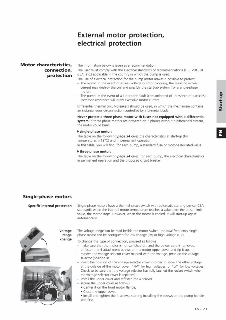
Motor characteristics, connection, protection
The information below is given as a recommendation.The user must comply with the electrical standards or recommendations (IEC, VDE, UL, CSA, etc.) applicable in the country in which the pump is used.The use of electrical protection for the pump motor makes it possible to protect:– The motor: in the event of excess voltage or rotor blocking, the resulting excess
current may destroy the coil and possibly the start-up system (for a single-phase motor).
– The pump: in the event of a lubrication fault (contaminated oil, presence of particles), increased resistance will draw excessive motor current.
Differential thermal circuit-breakers should be used, in which the mechanism contains an instantaneous disconnection controlled by a bi-metal blade.
Never protect a three-phase motor with fuses not equipped with a differential system: if three phase motors are powered on 2 phases without a differential system, the motor could burn.
single-phase motor:The table on the following page 24 gives the characteristics at start-up (for temperatures ≥ 12°C) and in permanent operation.In this table, you will find, for each pump, a standard fuse or motor-associated value.
three-phase motor:The table on the following page 24 gives, for each pump, the electrical characteristics in permanent operation and the proposed circuit breaker.
External motor protection, electrical protection
Voltage range
change
Single-phase motors have a thermal circuit switch with automatic starting device (CSA standard): when the internal motor temperature reaches a value over the preset limit value, the motor stops. However, when the motor is cooled, it will start-up again automatically.
The voltage range can be read beside the motor switch: the dual frequency single-phase motor can be configured for low voltage (LV) or high voltage (HV).
To change this type of connection, proceed as follows:– make sure that the motor is not switched on, and the power cord is removed,– unfasten the 4 attachment screws on the motor upper cover and tip it up,– remove the voltage selector cover marked with the voltage, press on the voltage
selector (position II).– invert the position of the voltage selector cover in order to show the other voltage
at the outside of the motor cover: “HV” for high voltages, or “LV” for low voltages. Check to be sure that the voltage selector has fully latched the rocket switch when the voltage selector cover is replaced.
– install the upper cover and refasten the 4 screws.– secure the upper cover as follows: • Center it on the front motor flange, • Close the upper cover, • Install and tighten the 4 screws, starting installing the screws on the pump handle
side first.
Single-phase motors
Specific internal protection

EN – 24
Three-phase motors
Electrical connections
Terminal box (9 wires)
The pumps are equipped with 9 wire terminal box motors, the wiring diagram of the terminals is given as a rough guide only. In the event of doubt, only the plate in the terminal box should be used as a reference.
The characteristics and ratings of fuses and circuit breaker associated with standard pump motors, 5 to 21 m3/h, single-phase or three-phase.
Summary tables of various types
of motors
* Temperature = 12°C** aM : Motor-associated type fuse
Single-phase motor
Current atultimate pressure (A)
*Start-up current (A)
Proposedfuse protection (A)
Voltage/Frequency 50 Hz 60 Hz 50 Hz 60 Hz Standard Type aM**
100V 50/60Hz 5.0 3.5 30.0 34.0 20/20 8/6
115V 60Hz 4.0 35.0 20 6
200V 50/60Hz 2.5 2.0 14.0 19.0 10/16 4/4
220V 60Hz 2.0 20.0 16 4
230V 50Hz 3.5 8.0 10 4
Three-phase motor
*Start-up current (A)
Proposed circuitbreaker protection (A)
Voltage/Frequency 50 Hz 60 Hz 50Hz 60Hz
Low voltage
200V 50/60Hz 3.1 2.8 4 3.5
220V 50/60Hz 3.5 3.1 4.5 4
240V 50Hz 4.0 5
280V 60Hz 3.7 4.5
High voltage
380V 50Hz 1.5 2
415V 50Hz 1.6 2
480V 60Hz 1.6 2
* Temperature = 12°C

EN – 25
EN
Op
era
tio
n
Operation
Preliminary precautions
At start-up, before switching on the motor, check that the oil bath temperature is greater than 53°F (12°C).
The ambient operating temperature for the pump must be between 53°F (12°C) and 113°F (45°C).
Under these conditions, the stabilized pump temperature (at the front of the oil case) will be between 140°F and 158°F (60 and 70°C) (depending on operating conditions).
Special case - Synthetic oilsSynthetic oils are much more viscous when cold than mineral oils.Do not start up the pump at ambient temperatures below 59°F (15°C).For the same reason and to facilitate lubrication of the pump, pour a few drops of oil (l to 2 cm3) through the inlet orifice before starting.
In certain cases, when the pump is started up in cold ambient conditions, or with slightly contaminated oil, the current after start-up may remain high until the oil in the pump is heated up. These conditions are sufficient for the internal thermal protection to be activated, making start-up impossible (see pages 23 and 24).
Operatingtemperature
Before starting-upthe pump
• The performance and operating safety of this product can only be guaranteed if it is operated according to normal conditions of use.• The vacuum pump is also a compressor: incorrect operation may be dangerous. Study the user manual before starting up the pump.• The pumps are designed to prevent any thermal risk for user safety. However, specific operating conditions may generate temperatures which may justify particular attention on the part of the user > 70°C).• Product tightness is guaranteed for normal operating conditions when the product leaves the factory. It is the user’s responsibility to maintain the level of tightness particularly when pumping dangerous products (on C series pumps).
Check that the exhaust orifice is not blocked.

EN – 26
Start-up • When using a three phase motor, check the direction of rotation of the motor (see electrical connections start-up chap. page 22).
• Check the oil level (see page 19).
• Start-up the pump.
• Allow the pump to run for one hour with the inlet blocked at ultimate vacuum:During this operation, make sure that the oil circuit is operating. Remove one of the oil fill plugs to listen to the pump.
At start-up, the oil enters the lubrication circuit of the vacuum pump. As a result, noises will be heard (first irregularly, then regularly) which will reduce as the oil heats up. These noises will no longer be heard when the fill plug has been replaced.
Under normal temperature conditions, the oil circuit should start less than 1 minute after start-up (this time may vary with the type of oil and its degree of contamination).
• Using the gas ballast:– to decontaminate the pump’s oil;– to accelerate heating. It is normal for the oil level to change (as can be seen through
the oil sight glass) when the pump is hot, due to expansion of the oil, starting of the oil circuit and the operating conditions of the pump (inlet pressure). If necessary, stop the pump and adjust the oil level between the “max” and “min” levels on the sight glass.
In the event of a malfunction, refer to the “Troubleshooting and corrective actions” table (page 34).

EN – 27
EN
Op
era
tio
n
Operation of gas ballast
Pumping condensable vapours
In a pump stored with the same oil for a long time, condensed vapours may contaminate the oil bath and affect performance. This is also the case after pumping vapours and when the oil appears cloudy or discolored through the sight glass.– Run the pump, shutting it off from the system at the inlet by a valve or a plug.– Open the gas ballast and allow the pump to operate for 1/2 hour to 1 hour, or longer
if the oil remains cloudy. This operation accelerates the temperature rise of the pump while eliminating residual vapours present in the oil bath.
To pump with condensable products, it is necessary to operate with a hot pump. For this, isolate the pump from the system and allow it to operate for 1/2 hour with the gas ballast open, or 1 hour (if possible) with the gas ballast closed. When the oil bath is hot, the condensation of vapours in the pump is reduced or prevented.
The pump’s capacity to eliminate condensable vapours is related to their type, the pump temperature and the quantity of air introduced by the gas ballast. Thus, for high vapour levels in a system, the single-stage pump is more suitable. However, when not pumping vapours, its ultimate pressure is higher. Care should be taken to limit the inlet pressure of the pump to its maximum admissible water vapor pressure with the pumped product. This is obtained by reading the pump characteristic table for water vapour (see page 9 to 11).
The use of cold traps or condensers are recommended when large quantities of vapours are to be extracted. Excessively intense or prolonged pumping may cause the products condensed in the trap to be evaporated a second time.
Choose an oil which facilitates the separation of pumped products which may be condensed in the oil bath (anti-emulsion oil for water-based compounds, etc.) (see page 17).
The condensation of vapours at the pump exhaust is reduced if:– the pump and oil temperature are high;– the pressure at the exhaust is as low as
possible (removal of the oil mist eliminator...);– the condensates are collected separately
from the oil bath and do not block the exhaust duct.
For this:– avoid using any vertical ducting which
promotes the condensation of products and the return of these products to the pump.
– use a condensate collector;– we do not recommend an oil mist eliminator
when pumping condensable vapors: if it is essential, do not connect it directly to the pump exhaust but place it outside the condensation zone.
– remove the stop valve from the pump exhaust;
– if possible, connect the exhaust to a mechanical device creating a negative pressure from 0.1 to 0.2 bar.
In. Exh.
Regeneration of pump oil
Choice of oil
Assembly
Choice of pump and system
In. Exh.
Condensate traps

EN – 28
– Valve off the pump from the system and increase the pump temperature, 30 minutes with gas ballast (see page 26).
– Start pumping and check the oil level: • the level drops, oil is being lost; • the level rises, condensates have been added to the oil.– After pumping, regenerate the oil using gas ballast if it is cloudy or discoloured. • if the level is too high, change the oil and regenerate.– Change the oil as soon as inlet pressure characteristics drop and are not improved by
regeneration.
Operating mode

EN – 29
EN
Op
era
tio
n
The use of vane pumps may result in pumping gases or vapours which are flammable or that could contaminate the oil. In this case, these products must be diluted using purges supplied with dry gases, such as nitrogen to avoid undesirable reactions.
For this purpose, a filtered dry nitrogen supply or other inert gas with the same characteristics is required:– condensation point < 22°C,– dust < 1μm,– minimum absolute pressure 2 bar.
The purge dilutes pumped gases with a neutral gas:it makes it possible to limit corrosion in the oil case, condensation and accumulation of gases in dead spaces of the pump.
Connect the nitrogen supply to one of the unused filling plugs on the oil case (BSPP 1/8 Gas connection).Set the nitrogen pressure to approximately 1,2 PSIG (0.1 relativ bar) (flow 50 to 300 l/h) and the flow rate so as to satisfy the dilution conditions.Caution: do not generate an excess pressure > 14 PSIG (1 relativ bar).
A neutral gas supply can also be connected via the gas ballast (BSPP 1/8 Gas connection).
Due to the danger represented by the accidental opening of the gas ballast on a C2 series pump, manual operation of the gas ballast has been disabled. However, it is possible to disassemble it and connect it directly to a neutral gas line (BSPP 1/8 Gas connection).
The nitrogen flow rate should be from 900 to 1000 l/h with a pressure of 1 to 1,2 PSIG (0.05 to 0.1 relativ bar).
The bubble device is composed of an air tube with several holes, located at the bottom of the oil case, which releases bubbles of neutral gas in the oil. In this way, the oil is saturated with neutral gas, which reduces its capacity to dissolve pumped gases. The bubbles of neutral gas released make it possible to eliminate the volatile vapours or acids condensed in the oil. The bubbler flow also lowers the pumps temperature which slows corrosion.
Remove the plug (1)
At this place connect in the coupling (2), the neutral gas supply (BSPP 1/8 Gas connection ), without unscrewing the coupling (2) and the connector (6).
Purges for pumping condensable, corrosive, and hazardous gases
All pumps models
Purges
Use of purge with gas ballast
Oil case purges
C2 models
Purge with gas ballast
Use of the bubbler
Neutral gas supply connecting to the bubbler Neutral gas
Never unscrew the coupling (2) and the connector (6) from the housing.

EN – 30
The gas flow rate is adapted according to the application and the installation, taking the following criteria into account (flow 60 to 500 l/h):
• When pumping high quantities of gas, a highly corrosive gas or an easily condansable gas, it is recommended to use a high nitrogen flow rate.Caution ! It is assumed that a sufficient quantity of nitrogen is available.• The pump exhaust circuit must be such that, for discharged flow rates, pressure drops do not cause an abnormal excess pressure in the oil case.
• The nitrogen flow rate must be such that oil losses have no effect on the operation of the pump throughout the pumping cycle (the oil level must be above the lower limit of the sight glass at the end of pumping).
Run the pump at ultimate vacuum for one hour and set the nitrogen flow rate as follows (at atmospheric pressure and at 20°C).
C2 Series Pumps Nitrogen flow rate in l/h Corresponding absolute pressures (bar)Min Average Maxi
60 200 500 1.05 to 1.10
Note: these characteristics apply for pumps operating at a constant inlet pressure (1 to 5 mbar): they are adapted for each case of pumping.
Start-up the pump at ultimate vacuum. When it is hot, run the nitrogen purge. Use it from the beginning and throughout pumping.
When pumping stops, allow the purge to operate for approximately 1 hour (depending on the quantity of pumped gas) at ultimate vacuum, with the purge, in order to degas the oil effectively and clean the pump with nitrogen to eliminate the traces of pumped gases.
Settings
Start-up
Stop

EN – 31
EN
Op
era
tio
n
Oxygen pumping
In certain applications, mixtures containing oxygen at different concentrations, or even pure oxygen, are used.
Oils of mineral origin are combustible. Exposure to pure oxygen at high temperatures may cause them to self-ignite. In addition, they are highly oxidized during pumping and quickly lose their lubricating properties. Mineral oils must not be used for oxygen levels of over 21 % in pumped gases. In this case, perfluorinated synthetic oils must be used, see list on page 17.
The use of these oils requires a special pump preparation (see page 38). The pump must be completely disassembled and all traces oil mineral oil removed. Flushing the oil case is not adequate.
Any accumulation of oxygen in the installation should be avoided and the oxygen or combustible mixture should be diluted with a neutral gas at the exhaust: the gas flow rate should be 4 times the oxygen flow rate.
Certain combustible or explosive gases require a higher degree of dilution. Our Support Services and Customer Services can advise you to help solve problems of this kind.
In addition, it is strongly recommended not to use fluids such as tri-aryl-phosphate-ester which are known to cause accidents.

EN – 32
Recovery of oil (high pressure and cycling)
For intermittentpumping
When the pump operates at high pressure, the oil heats up, becomes more fluid and is flushed out of the functional block by the gas stream.
Oil losses at the exhaust are increased.
If the pump only operates for a very short time at high pressure, the lubricating oil is replaced when the pump returns to low pressure. The use of a oil mist eliminator prevents losses due to intermittent high pressure operation.
If the pump operates at high pressure in a cyclical fashion, oil consumption may reach sufficiently high levels (according to the pumped volume and pumping cycle rates) causing the level to drop in the oil case.
There is then a risk of seizure due to a lack of oil. In addition, the high flow of gas passing through the eliminator prevents oil from returning to the oil case.
In order to pump in these conditions, the pump must be equipped with an OME 25 HP type oil mist eliminator and an ODK oil draining kit, which enables oil recovery via the gas ballast.
For continuous pumping at high
pressure
For cyclical pumping
In this case, or when very large volumes (requiring several hours of pumping) are being pumped, it is recommended to recover the oil via the pump inlet.
In this case, please consult us directly.
Cyclical pumping:
ODK type oil recovery device
OME 25 HP + ODK 1 Device is not tight when
switched off.
OME 25 HP + ODK 2An electrovalve ensures
tightness when switched off.
In. In.Exh. Exh.

EN – 33
EN
Main
ten
an
ce
General precautions
Maintenance
For normal operation, the maintenance of 5 to 21 m3/h series pumps only require regular oil changes (see page 37).
Always dispose of used dirty oil, or sub-products properly and in compliance with all local, state and federal environmental laws and regulations.
Certain gases can become corrosives and toxic when trapped in oil. Always wear protective gloves when handling used and dirty pump oil, drain it into a closable container,and do not breathe the fumes of the oil. Always use fully self-contained breathing apparatus.
Before any draining or maintenance operation, check the pumping conditions of the installation: potential toxicity, corrosion or radioacitivity of pumped gases.Depending on the case, we recommend:– to purge the pumping installation with dry nitrogen before maintenance;– wear gloves, protective goggles and, if necessary, a breathing apparatus;– ventilate the premises well and disassemble the equipment under a suction
hood;– not to dispose of used oils and residues using the standard system and, if
necessary, have them destroyed by a specialized company.
After a complete maintenance operation, it is recommended to perform a helium leak tightness test.The manufacturer can provide specific training to know the tightness test methods and supply helium leak detectors. Contact us.
Decontamination – product dismantlingAccording to the regulations 2002/96/CE about Waste of electrical and electronical equipments, and 2002/95/CE about Restriction of Hazardous substances, the manufacturer provides a recycling paid service for the end-of-life of waste electrical and electronic equipment.Any obligation of the manufacturer to take back such equipment shall apply only to complete not amended or modified equipment, using Alcatel Vacuum Technology original spare parts, delivered by Alcatel Vacuum Technology, containing i.e. all its components and sub-assemblies. This obligation will not cover the shipping cost to an Alcatel take back facility.Before returning the product, fill in the safety form, attach it to the product before shipping to the service-repair office closest to you.Safety form available on this manual or can be downloaded on: www.adixen.com

EN – 34
Incidents Causes Corrective actions
The pump is not running Incorrect motor power supply. Check the power supply.
Temperature too low. Reheat the pump and its oil.
Gumming of seals after prolonged storage.
Disassemble the motor and try to turn the fan manually.Disassemble, clean the pump, replace seals, reassemble.
Oil contaminated after pumping. Drain, flush and refill with cleanoil.
Motor coupling damaged. Replace by disassembling the motor.
Pump seized, due to a stopping after pumping in difficult conditions (no draining or flushing).
Disassemble, clean, hone the scratched metal parts (replace them if necessary) and reassemble.
The pump does not start Oil cold. Warm pump.
Insufficient oil in the oil case. Fill up to the level.
Oil contaminated. Drain, flush and refill with cleanoil.
Oil pump inlet partially blocked. Drain, and clean the oil pump inlet duct.
Lubrication holes blocked. Disassemble and clean.
Vane or spinner-cam (SD models) damaged.
Replace them.
Incorrect anti-suckback system assembly.
Repeat the assembly and the setting.
The vacuum pump does not produce a vacuum
Ultimate pressure obtained: a few mbar, Torr
Direction of motor rotation incorrect (three phase).
Rewire.
Insufficient motor power. Check the power supply.
Inlet filter blocked. Clean it.
Insufficient oil in the oil case. Add oil.
Oil cold, oil pump inlet blocked. Warm, disassemble, clean.
Oil contaminated. Drain, flush and start again with clean oil.
Oil pump inlet partially blocked. Drain and clean the oil pump inlet duct.
One of the LP safety valves is damaged.
Replace.
Part forgotten in reassembly. Repeat the reassembly.
Troubleshooting and corrective actions

EN – 35
EN
Main
ten
an
ce
Incidents Causes Corrective actions
The vacuum pump does not produce a vacuum (continued)
Ultimate pressure obtained: a few 10-2 Torr (10-2 mbar)
Gas ballast adjustment button open. Close.
O-ring pinched. Replace.
One of the seals is damaged. Replace.
One of the HP safety valves is damaged.
Replace.
Lubrication holes blocked. Disassemble and clean.
Incorrect anti-suckback assembly. Repeat the assembly and setting.
Part forgotten in reassembly. Repeat the reassembly.
Accessories
At the pump exhaust, the installation produces an exhaust pressure of 1,125 Torr (1.5 bar).
Check the installation.
Oil mist eliminator cartridge clogged. Replace.
Noisy pump Oil level too high. Drain and fill with a new oil.
Oil contaminated (presence of particles).
Drain, flush and refill with cleanoil.
Pump not prepared for the oil used. Check the pump configuration or the type of oil.
Incorrect motor power supply. Check the power supply.
Motor bearings damaged. Replace the motor after inspection.
Motor coupling incorrectly set or damaged.
Check the setting.
Incorrect fan assembly. Check the assembly.
Incorrect anti-suckback device assembly.
Repeat the assembly.
Vanes damaged or stuck. Replace.
Pump too hot Ambient temperature too high.
Pump placed in a poorly ventilated place or vents blocked.
Check the installation.
Operation at high pressureP > 22 Torr (30 mbar).
Check for system leaks.
Excess pressure at exhaust. Check the exhaust line.
Motor in over-voltage or motor in short-circuit.
Check the voltage, replace the motor.
Oil contaminated. Drain, flush and refill with cleanoil.
Pump not prepared for the oil used or oil unsuitable.
Check pump configuration or type of oil.

EN – 36
Incidents Causes Corrective actions
Considerable oil losses Oil level too high. Drain and fill with new oil.
Operation at high pressure. Use an HP type oil mist eliminator with oil recovery.
Gas ballast open:1 - accidentally,2 - pumping of condensable vapours.
1 - Close.2 - Use a condensate collector.
Leak at oil case seal or at front seal. Check the assembly and replace the seals if necessary.
Poor pump tightness when switched off
Gas ballast open. Close.
Safety valve damaged. Replace.
Incorrect anti-suckback assembly. Repeat the assembly.
O-ring pinched. Replace.
Seals damaged. Replace.
Oil contaminated. Drain, flush and refill with cleanoil.
Oil in plate Oil case and frame cleaned poorly during reassembly.
Remove the base and clean.
Oil case seal pinched. Disassemble the oil case, clean the faces and refit a new seal.
Front seal damaged or felt saturated. Replace.

EN – 37
EN
Main
ten
an
ce
Maintenance
Maintenance frequency
Frequency Operating conditions
Oil6 months “normal”, 24 / 24h
1 year “normal”, < 12h / day
Pump1 year “normal”, 24 / 24h
2 years “normal”, < 12h / day
The frequency values are minimum values for «normal» operating conditions: pressure < 1 mbar (0.75 Torr), clean gas and non-corrosive gas.
An incorrect ultimate vacuum or a reduction in pumping speed are signs that the oil has deteriorated.The periodic inspection of the state of the oil is performed by comparison with a sample of new oil in order to check the level of contamination or deterioration of the lubricant.The frequency at which oil is renewed is adapted to the type of operation:– if the oil is cloudy, this indicates that condensables have been absorbed during
pumping. The oil can be regenerated using the gas ballast (see page 27).– a thickening of the oil, together with a blackish color and a “burnt” smell indicate
that the oil has deteriorated.Drain the pump and flush it.
The oil should be changed every 6 months. This value is given as a guide only. It may be extended to 1 year if the ultimate vacuum required is sufficient (for primary vacuum pumps). Similarly, if the pump is stopped frequently for long periods, the oil should be changed at intervals of 6 months to a maximum of 1 year (oil may become sticky).
Note: Every pumping operation is different. This oil must therefore be changed at intervals adapted to each specific application. The use of certain accessories (see page 13) can reduce the frequency of these maintenance operations.
Draining
The pump must be drained when hot and after the oil case has been vented to atmospheric pressure. For this:– switch off the pump;– isolate the pump or disconnect from the
installation;– tilt the pump;– unscrew the draining plug on the side of the
oil case and the filling plug on the top of the oil case.
When all the oil has drained, replace the two plugs temporarily and run the pump for about 10 seconds leaving the intake open. Take care with the oil mist which may appear at the exhaust. This operation removes the oil from the functional block;– drain this oil by removing the draining plug;– replace the draining plug and fill with fresh oil to the appropriate maximum level of
the oil case oil sight glass through the filling orifice (see page 18).
The draining operation places the contaminated pumping circuit in communication with the outside atmosphere. Take all necessary steps to ensure personal safety.

EN – 38
Flushing The draining operation can be followed by a flushing operation if the oil is particularly dirty. This operation requires a volume of oil equal to the capacity of the pump.
After draining the oil case (see page 37), replace the draining plug. Remove the intake filter, clean it and replace it. Run the pump at atmospheric pressure, pour the flushing oil very slowly through the inlet orifice. Take care with oil mist which may develop at the exhaust. Stop the pump and drain the flushing oil via the draining plug. Replace the plug and fill with fresh oil (see page 18).
5 to 21 m3/h series pumps are tested in the factory with A120 oil or A119 for USA (A113 for C2 series pumps) unless specified otherwise in the order. When the pump is delivered, a certain quantity of oil remains in the functional block.Thus, if you wish to use another type of oil, proceed as follows:
Mineral oil can be replaced by another type of mineral oil. Simply flush the pump (see above) using the new oil and fill the pump (see page 18).Mineral oils are also compatible with mineral-based synthetic oils (see page 17).
This is the case when, for example, a mineral oil is replaced by a synthetic oil (e.g. A120 by A113).Synthetic oils are considered to be incompatible with each other for practical reasons: they are expensive. A mixture may cause slight cloudiness of the resulting mixture, which could be interpreted mistakenly as a sign of contamination or deterioration.For the same reasons, clear synthetic and mineral oils (A300), which are also expensive, are treated as synthetic oils.
These remarks apply to ester or fluorocarbon type synthetic oils and the oils A111, A113 and A300 (see page 17).
Proceed as follows:– Disassemble the pump completely and clean it (see page 42).– Reassemble it.– Connect an oil mist eliminator to the pump exhaust.– Fill the pump with the new oil (see page 18).
NOTE: to replace a synthetic oil by a mineral oil, proceed as for compatible oils.
Incompatible oils
Compatible oils
Change of type of oil
In all cases, follow the recommendations of the pump integrators for the choice of the oil to be used.

EN – 39
EN
Main
ten
an
ce
Replacement of external shaft seal
In the event of an external oil leak on the pump, it is necessary to change the external shaft seal on the motor side (see page N – 4).
You will need:– a front seal replacement kit (see page 40),– a screwdriver,– a 3, 4 and 5 mm Allen wrench.
• Stop the pump and disconnect the power cord motor.
• Disconnect the pump from the installation to which it is connected.
• If possible, position the pump vertically, with the motor at the top, resting on the front side of the oil case; in this position, it is not necessary to drain the oil case. Otherwise, disassemble the pump in the horizontal position, resting it on its base, after it has been drained.
• Disconnect the motor by unscrewing the 4 fastening screws, simultaneously and alternately.
• Remove the motor vertically.
• Unscrew the fan fastening screw. Remove the fan, the key and the support washer.
• With a screwdriver, remove the shaft sleeve (36) and its O-ring (35).
• Unscrew the two seal-holder fastening screws (37, 38) and remove the seal-holder (39).
• Remove the seal (40) from the seal-holder as described on page 46 (picture 1) and discard it.
• Clean the metal parts. Inspect the wearing side of the shaft sleeve: after cleaning, the sleeve may show a perfectly normal trace of rubbing (caused by polishing). Should the sleeve show any signs of indentation or grooves, it must be replaced.
• Preferably use new parts from the seal kit or set of seals.
• Reassemble the lip seal (40) in its housing as described on page 46.
• Reinsert the new O-ring (41a) on the seal-holder (39).
• Insert the shaft sleeve inside the seal-holder (36).
• Engage the reassembled seal-holder on its axis and screw onto the frame.
• Insert the O-ring (35) in the shaft sleeve. Position the support washer. Then, install the key, reassemble the fan and the motor in the reverse order of disassembly.
• Immediately order a replacement maintenance set or kit (see page 40).
35 36 39
4041a
3738

EN – 40
Tools and consumable products
Special precautions
Major kit
Spare parts
Minor kit This kit contains all the seals on the pump which must be replaced at each complete disassembly.
Pumps 1005 1010 1015 1021 2005 2010 2015 2021
I – 103912
SD 103911 105515 103911
C1 104975
C2 – 104975
Keep this kit in a dry place, away from heat and light (sunlight and ultraviolet light), in order to prevent any hardening of the elastomers (see AFNOR standards: “storage conditions for vulcanized elastomer based products” - FD T.46 022).
In addition to the seal kit, this kit contains a set of spare parts to perform maintenance operations on the pump for a two year period, under normal operating conditions.
The pumps are equipped with :• a shouldered not chromed ring (36) for I and SD models with serial number
< AM656245• a shouldered chromed ring (36) for I and SD models with serial number
≥ AM656245• a shouldered chromed ring (36) for C1 and C2 models.
The shouldered not chromed ring is a spare part that must be replaced. It is enclosed in the major kit.
The shouldered chromed ring needn’t to be changed. It is not enclosed in the major kit for I and SD models. However, it is available in the external shaft seal kit (see page 41).
Pumps 1005 1010 1015 1021 2005 2010 2015 2021
I – 103906 103907 103908 103909
SD 104622 104623 104643 104644 103902 103903 103904 103905
C1 104617 104618 104619 104620 104976 104977 104978 104979
C2 – – 104614 104615 104616
Read the warning at the beginning of the maintenance chapter.Before disassembling the pump, drain it (see page 37).All the seals and faulty parts should be replaced, provided in a seal kit or a maintenance kit.

EN – 41
EN
Main
ten
an
ce
Vane kits for 2-stage pumps This kit contains only vanes and springs in order to maintain several pumps of the same model (see table here after).
Pumps 2005 2010 2015 2021
LP stage vane kit 108417 108396 108397 108398
Vane / Spring (quantity) 20 / 20 20 / 40 20 / 60 20 / 60
HP stage vane kit* 108417 108399 108399 108399
Vane / Spring (quantity) 20 / 20 20 / 20 20 / 20 20 / 20
* except model C2.
Pumps 2005 2010 2015 2021
Oil vane pump kit** 108407 (10 vanes)
** except model SD.
External shaft seal replacement kit (parts for shaft passage
tightness on motor side)
This kit contains all the parts which must be replaced in the event of a leak on the shaft on the motor side.
Screw kit
Recommended tools
This kit contains all screws and washers for all pump models.
• Two 5.5 x 100 flat screwdrivers
• Thin spanner: 10 mm on face
• Allen wrenches: 2.5 - 3 - 4 - 5 - 12 mm 5
• 12 mm box wrench
HP and LP no flanged stator (plan D)
HP flanged stator(plan C)
LP flanged stator (plan C)
Lip seal assembly mandrel A462651 A462651 A462651
Support washer 073348 073348 –
Protective sleeve A463545 A463545 A463545
Lip seal disassembly mandrel – – A462649
Pump models Part Nu.
All pumps 104919
Tools kit This kit contains the usefull tools to disassemble and reassemble the shaft seals in the different flanges and flanged stators (see table bellow).
Pump models Part Nu.
All pumps 112397
Specific tools
Pump models Part Nu.
All pumps 065612
Protective sleeve Lip seal disassembly mandrel

EN – 42
Disassembling the pump
Disassembling the motor block
Remove the motor cover.
5 Remove the motor attachment screws (see page N – 18).
Remove the fan (33) fastening screw (28) and the support washer (26).Remove the key.
See page 39.
Remove the gas ballast cover (58)(2 screws), the adjustment button (55), the spring (54) and the sleeve (53).
Remove the tank feed-through (49) (2 screws) and its seal (48).
Remove the sight glass cover (3).
Remove the plate (1), the ring (4a) (model C1), the sight glass (4) and the O-ring (5).
5 Remove the oil case (6) and its O-ring (11) after removing the 4 fastening screws (9).
Disconnect the nitrogen inlet. Remove the nitrogen inlet and disconnect the coupling (2) and the connector (6).
Disconnect the nut (16) which secures the tube on the functional block and pull the bubble (8) to release it from the frame.
Disassembling the fan coupling
(see page N – 2)
Replacing the front seal
Disassembling the gas ballast
except model pump C2(see page N – 2)
Disassembling the oil sight glass
(see page N – 2)
Removing the oil case(see page N – 2)
Disassembling the bubbler (C2 pump)
(see page N – 20)
Follw the chronological order of disassembling instructions.See the drawings and their part lists in pages N – 1 to N – 20.
cover
5
1
3
6
28
33
55 58 54
4948
53
1 4 4a
5
2 8

EN – 43
EN
Main
ten
an
ce
Disassembling the SD pump oil system
(except 1015 SD, 1021 SD)(see page N – 16)
The oil system is set in the factory, it must be reset in the event of disassembly (see reassembly). However, the rear flange (4) can be disassembled without modifying the setting.Remove the spinner-cam (6) by removing the circlip (7).Do not disassemble the nozzle (8) to clean it. During the reassembly, check that it is not blocked by sending a jet of compressed air through it.
5 Remove the cover from the oil pump (1). Release the cylinder (13) equipped with the washer (14), piston (11) and spring (12).
Release the stop valve (10) from its housing.
In the rear flange, unscrew the seat of the stop valve (9) and remove the O-ring (8).
Then remove the vane (4), the oil pump rotor (3) and the Oldham coupling (5).
Disassembling the exhaust valve cover
(see page N – 6)
5 Remove the screws (4) (13) (15) and the cover(s) (6) (17), the exhaust valves (2) (11) and their springs (3) (12).
Disassembling the pump oil system
I, C1, C2 pumps and 1015 SD, 1021 SD
(see page N – 14)
Remove the 4 nuts. Release the flange (7) in the axis.Disassembling therear flange
(see pages N – 14 et N – 16)
4 13
6 17
15
4
6
1
114
8
9
3
4
5
12
13
10
11
7
7
8

EN – 44
Disassembling the pumping module
with flanged stator(see N – 10)
1 Insert two screwdrivers in the notches and release the set HP stator (34) and HP rotor (31) in the axis.
2 Release the HP rotor (31) from the HP stator (34) and the vanes.
3 Insert two screwdrivers in the notches and release the set BP stator (26) and BP rotor (23) in the axis.
4 Release the BP rotor (23) from the BP stator (26) and the vanes.
31
34
34 31
232623
26

EN – 45
EN
Main
ten
an
ce
Disassembling the pumping module
with no flanged stator
(see N – 6)
1 Remove the HP stator (34) by sliding it along the HP rotor (31).Remove the HP rotor and the vanes.
2 Insert two screwdrivers in the notches and release the central plate (29) in the axis.
3 Insert two screwdrivers in the notches and release the BP stator (26) by sliding it along the BP rotor (23).Remove the BP rotor and the vanes.
4 Release the front plate (19).
31
34
23
26
29
19
EN – 46
Cleaning components
Cleaning metal components
Cleaning the oil level sight glass
I, SD, C2 series pumps
Solvents are required to clean components.
Standard precautions should be taken in compliance with the manufacturer's instructions.
After use in mineral or synthetic oil, clean the metal components with a mineral products based solvent such as AXAREL(1) , CARECLEAN(2), PREMACLEAN(3), NAPHTESOL(4). Proceed as follows:• Clean when cold or hot (max. 45°C) by dipping or using a cloth• Vacuum dry in a ventilated oven• The component must be cleaned a second time with alcohol.
After use in (perfluorinate) synthetic oil, clean the metal components in a solvent such as GALDEN S 90™(5) and proceed as follows:• Clean when cold by dipping or using a cloth• Dry the components in the air or with compressed air
After use in (non-perfluorinate) synthetic or mineral oil, clean the metal components with a solvent such as alcohol and proceed as follows:• Clean when cold by dipping or using a cloth• Dry the components in the air• Industrial washing solutions can also be used. The cleaning operation should be
followed by vacuum drying.
When cleaning this plastic sight glass, avoid contact with alcohol or alcohol-based washing solutions. Clean the component with a solvent, but do not steep it, and rinse it immediately.
The sight glass of these pumps is made of glass: it can be cleaned with common used solvents.
(1) DUPONT DE NEMOURS registered trademark(2) CASTROL registered trademark(3) DOW registered trademark(4) Nippon Oil Corporation registered trademark(5) MONTEDISON registered trademark
C1 series pumps

EN – 47
EN
Main
ten
an
ce
Replacement of shaft seals
Recommended tools
• Specific extraction tool.• Specific assembly mandrel.• A support plate (or washer).
• A flat screwdriver .• A hammer.
• Flange (picture 1): the seal is extracted using a screwdriver, resting on the plate (or washer) so as not to damage the seal housing, or
• Flanged stator (picture 2): the seal is extracted with the specific extraction tool.
The seal housing and the seal lip are lubricated with the lubricant used in the pump.The flange is resting on a flat surface.
According to the direction of assembly specific to each pump, the seal is fitted on the assembly mandrel.
Using a press or a hammer, the seal is inserted in its housing.
Check the position of the seal: it must lean against its bearing.
They are fitted using the assembly mandrel according to the direction of assembly below:
Direction of assemblyof shaft seals
Assembling the shaft seal
Extracting a shaft seal from its housing
ø 24.5 ± 0.1
5.5 ± 0.210
5*
ø 14+0.20 1
à 45 C
+0.20
Picture 1
Picture 2
Mandrel
* m
inim
um d
imen
sion
for
the
spe
cific
ext
ract
ion
tool
.
Specific tools
HP rotor
frame
rear fl ange
front fl ange
seal-holder
medianfl ange
Assembly of pumping module with no flanged stator drawing (D)
HP stator
LP rotor
LP stator
washer
extraction tool
HP rotor
frame
rear fl ange
seal-holder
HP stator
LP rotor
LP stator
Assembly of pumping module with flanged stator drawing (C)

EN – 48
• All surfaces in contact are coated with oil.• Check that the lubrication holes are not blocked.• Observe the nominal clamping torques for the reassembly of the functional
block (see chapter “Nomenclature”).• Rest the frame (42) on a flat surface in order to raise the pump.
Reassembling the pump
Component preparation
Reassembling the pumping module
with flanged stator(see N – 10)
1 Place the BP stator (26) on the frame (42).
2 For not damage the shaft seal, use protective sleeve on the rotor axis (or wrap end of shaft with adhesive tape) and oil it.
3 Slide the BP rotor (23) equipped with its vanes and springs (rounded edges facing outwards) in the BP stator (26). Remove the protective sleeve
4 Place the HP stator (34) on the BP stator (26).
5 Slide the HP rotor (31) equipped with its vanes and springs (rounded edges facing outwards) in the HP stator (34).
6 Place the rear flange (7) on the HP stator (34).
Sleeve
26
23
31
34
7

EN – 49
EN
Main
ten
an
ce
Reassembling the pumping module with no flanged
stator(see N – 6)
1 Fit the front plate (19) on the frame (42).
2 For not damage the shaft seal, use protective sleeve on the rotor axis (or wrap end of shaft with adhesive tape) and oil it.
3 Place the BP Rotor (23) equipped with its vanes and springs (rounded edges facing outwards) on the front plate (19). Remove the protective sleeve.
4 Slide the BP stator (26) on the BP rotor (23).
5 Place the central plate (29) on the BP stator (26).
6 Place the HP rotor (31) equipped with its vanes and springs (rounded edges facing outwards) on the central plate (29).
7 Slide the HP stator (34) on the HP rotor (31).
8 Place the rear plate (7) on the HP stator (31).
Sleeve
347
2931
2326
19

EN – 50
a
d
c
b
C1 series pump: The sight glass is made of glass: gradually tighten the two attachment screws in alternation to avoid placing the sight glass under stress.
Reassembling the oil casing
(see page N – 6)
Check that the nozzle is not blocked by sending a jet of compressed air through it.
Place the spinner-cam system on the rear plate (4) and fix it with the clips (7).
Offset the spinner-cam (a) by pressing on the blades.
Turn the shaft up to the maximum displacement of the lever (b).
The distance between the seat (c) and the stop valve (d) must be 0.9 to 1.2mm (0.035 to 0.047 inch): it is set by adjusting the orientation of the lever.
The stop valve face must be perpendicular to the axis of the oil inlet hole; when free,the stop valve should rest on its seat: check the parallelism of the lever in relation to the bearing face of the stop valve seat. Orient the seat to obtain the correct setting.
In the rear plate (7), place the Oldham coupling (5), the vane (4) and the rotor (3).
Screw the seat (9) equipped with its O-ring (8). Place the piston (11) with its antisck-back device (10), the spring (12), the cylinder (13) and the washer (14).
Position the rotor of the oil pump so that the slot is horizontal (or parallel with the pump base). To turn it, use the fan.
Pump in a horizontal position, pour a small quantity of oil beforehand around the exhaust valve holes.Place the valves (2) or (11) equipped with the springs (3) or (12)Place the valve covers (6) or (17) and fix them with screws and washers.
Insert the bubbler (8) equipped with its o-ring in the frame.Position the tube fastener (9) on the pin and tighten the nut on the rear plate (7).Insert the ball (4), the spring (5) in the coupling (2) and tighten it on the connector (6).
Fit the oil casing (6) equipped with its o-ring (11) on the frame (42).Tighten it with screw (9) and washers (10) ( after making sure that the seal is positioned in its seal groove).
Place the o-ring (5) in its groove and fit the sight glass (4), (the flat ring (4a) for C1 pump), the oil sight glass cover (3) and tighten with screws (2).
Reassembling the oil system
Reassembling the oil level sight glass
(see page N – 2)
Reassembling the exhaust valve cover
(see page N – 6)
Reassembling the bubble device
C2 pump (see page N – 6)
Spinner-cam, SD pumps (except 1015 SD and 1021 SD)
(see page N – 16)Spinner-cam settings
Oil pump, I, C1 and C2 pumps (and 1015 SD, 1021 SD)
(see page N – 14)
Oil pump settings

EN – 51
EN
Main
ten
an
ce
Reasembling the gas ballast
(see page N – 2)
Reassembling the seal-holder
(see page N – 2)
Reassembling the fan and the motor side
components(see page N – 2)
Position the oil case feed-through (49) equipped with its o-ring (48) in its housing by centering it on the gas ballast tube (46). Assemble using the screws (52).
Equip the adjustment knob (55) with the sleeve (53) and the spring (54). Position the assembly in the cover (58) and secure on the oil case feed-through (49) with screws (57).
See page 39.
Fit the coupling fan (33) and secure it with the screw (28) and washer (26).Fit the drive key on the motor shaft. Install the motor coupling (3) down to the stop on the motor shaft and secure it with the screw (2).Install the plastic coupling (4) on the motor coupling (3).Fit the motor on the frame and secure with the 4 mounting bolts (5).
After reassembling, fill the pump with oil (see page 18) before start-up the pump (see page 25).
Fill with oil
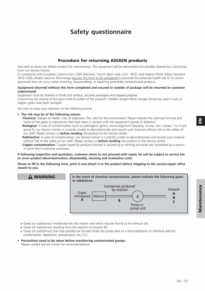
EN – 53
EN
Main
ten
an
ce
Safety questionnaire
Procedure for returning ADIXEN productsYou wish to return an Adixen product for maintenance. The equipment will be dismantled and possibly cleaned by a technician from our Service Centre.In compliance with European Community’s L360 directives, French labor code L231 - R231 and Federal OSHA Safety Standard 1910-1200, Alcatel Vacuum Technology requires this form to be completed to preclude the potential health risk to its service personnel that can occur when receiving, disassembling, or repairing potentially contaminated products.
Equipment returned without this form completed and secured to outside of package will be returned to customer unprocessed.Equipment must be drained of fluids and residue, securely packaged and shipped prepaid.Concerning the closing of the ports (inlet & outlets of the product), metallic airtight blank flanges should be used if toxic or copper gases have been pumped.
We wish to draw your attention to the following points:
• The risk may be of the following nature:- Chemical: Danger to health, risks of explosion, fire, risks for the environment. Please indicate the chemical formula and
name of the gases or substances that have been in contact with the equipment (pump or detector).- Biological: in case of contamination (such as pathogenic germs, micro-organisms (bacteria, viruses, etc.) classes 1 to 4 and
group E), our Service Center is currently unable to decontaminate and recycle such material without risk to the safety of our staff. Please contact us before sending the product to the Service center.
- Radioactive: In case of contamination, our Service Center is currently unable to decontaminate and recycle such material without risk to the safety of our staff. Please contact us before sending the product to the Service center.
- Copper contamination: Copper based by products formed in sputtering or etching processes are considered as a poison in some semi-conductor processes.
If following inspection and quotation, customer elects to not proceed with repair, he will be subject to service fee to cover product decontamination, disassembly, cleaning and evaluation costs.
Please to fill in the following form, print it and attach it to the product before shipping to the service-repair office closest to you.
■ Gases (or substances) introduced into the reactor and which may be found at the exhaust (A).■ Gases (or substances) resulting from the reaction or process (B).■ Gases (or substances) that may possibly be formed inside the pump (due to a thermodynamic or chemical reaction,
condensation, deposition, precipitation, etc.) (C).
• Precautions need to be taken before transferring contaminated pumps. Please contact Service Center for recommendations.
In the event of chemical contamination, please indicate the following gases or substances:
Gasesintroduced
A
Substances produced by reaction
Pump or pump unit
ExhaustABCB
Reactor C

EN – 54

EN – 55
EN
Main
ten
an
ce

N – 1
Nomenclature
Composants de maintenance / Maintenance components / Unterhaltung Teile
Plan de montage cuve et bâti .............................................Oil casing and central housing assembly drawing ....................Gesamtplan Ölbehälter und Pumpenträger ..................................2 / 4
Nomenclature cuve et bâti ..................................................Oil casing and central housing part list ....................................Nomenklatur Ölbehälter und Pumpenträger ................................3 / 5
Plan du bloc fonctionnel (avec stator non flasqué) (D) .........Pumping module drawing (with no flanged stator) (D) ............Gesamtplan Pumpenblock (mit Stator und Flansche) (D) ..............6 / 8
Nomenclature du bloc fonctionnel ......................................Pumping module part list (with no flanged stator) (D) .............Nomenklatur Pumpenblock (mit Stator und Flansche) (D) ............7 / 9(avec stator non flasqué) (D)
Plan du bloc fonctionnel (avec stator flasqué) (C) ................Pumping module drawing (with flanged stator) (C) .................Gesamtplan Pumpenblock (mit Stator monoblock) (C) .............10 / 12
Nomenclature du bloc fonctionnel ......................................Pumping module part list (with flanged stator) (C) ...................Nomenklatur Pumpenblock (mit Stator monoblock) (C) ...........11 / 13(avec stator flasqué) (C)
Plan du système de lubrification pompe à huile (A) .............Oil pump system drawing (A) ..................................................Gesamtplan (A) Ölpumpsystem ......................................................14
Nomenclature du système de lubrification .........................Oil pump system part list (A) ....................................................Nomenklatur (A) Ölpumpsystem .....................................................15pompe à huile (A)
Plan du système de lubrification levier moulinet (B) .............Oil system drawing (B) .............................................................Gesamtplan (B) Ölpumpsystem .......................................................16
Nomenclature du système de lubrification .........................Oil system part list (B) ..............................................................Nomenklatur (B) Ölpumpsystem .....................................................17levier moulinet (B)
Plan ensemble motorisation (M) ..........................................Motor assembly drawing (M) ...................................................Gesamtplan (M) Motor ...................................................................18
Nomenclature ensemble motorisation (M) ...........................Motor assembly part list (M) ....................................................Nomenklatur (M) Motor .................................................................19
Plan du système bulleur ......................................................Bubbler system drawing ..........................................................Gesamtplan Bubbler system ...........................................................20
Nomenclature du système bulleur .......................................Bubbler system part list ............................................................Nomenklatur Bubbler system ..........................................................20

N – 2
1
57
58
59
5554
5349
4847
4645
4343a
42
4141a
4039
3837
3635
3433
44
52
2
3
44a
5
67
8
11
1213
1415
1617
17a
23
18
19
20
21
22
2628
910
C
M
Bor
Dor
A
Rep. PartClamping torque
(DaN.m)
2 Screw FHC M5 x 10 0.4
9 Screw CHC M6 x 25 1.2
14 / 20 Screw FHC M6 x 12 1
28 Screw M5 x 16 (s.steel) 0.6
38 Screw CHC M6 x 12 1.1
45 Screw CHC M6 x 25 1.2
52 / 57 Screw CHC M4 x 10 0.4
Plan de montage cuve et bâtiOil casing and central housing assembly drawing Ölbehälter und Pumpenträger Gesamtplan

N – 3
Nomenclature
Nomenclature cuve et bâti / Oil casing and central housing part list / Ölbehälter und Pumpenträger Nomenklatur
REP DÉSIGNATION SPECIFICATION BENENNUNG
Types/modelREF.P/N
Bestell. Nr2005
I
2010
I
2015
I
2021
I
2005
SD
2010
SD
2015
SD
2021
SD
1005
SD
1010
SD
1015
SD
1021
SD
2010
C2
2015
C2
2021
C2
2005
C1
2010
C1
2015
C1
2021
C1
1005
C1
1010
C1
1015
C1
1021
C1
1 Plaque de niveau Level plate Ölmesstab 1 1 1 1 1 1 1 1 1 1 1 1 1 1 1 1 1 1 1 1 1 1 1 1033912 Vis FHC M5 x 10 Screw FHC M5 x 10 Schraube FHC M5 x 10 2 2 2 2 2 2 2 2 2 2 2 2 2 2 2 2 2 2 2 2 2 2 2 3 Cache de niveau Oil sight glass cover Ölschauglassdeckel 1028483 Cache de niveau Oil sight glass cover Ölschauglassdeckel 1 1 1 1 1 1 1 1 1 1 1 1 1 1 1 1 1 1 1 1 1 1 1 1028494 Voyant Oil level sight glass Ölschauglas 1 1 1 1 1 1 1 1 1 1 1 1 1 1 1 1 1 1 1 1 1 1 1 4a Joint de niveau Flat ring Flachdichtung 1 1 1 1 1 1 1 15 Joint torique c 3,53 - d 63,1 O-ring c 3.53-d 63.1 Dichtung c 1,9 - d 7,2 1 1 1 1 1 1 1 1 1 1 1 1 1 1 1 1 1 1 1 1 1 1 16 Cuve équipée Oil casing Ölbehälter 1 1 1 1 1035466 Cuve équipée Oil casing Ölbehälter 1 1 1 1035486 Cuve équipée Oil casing Ölbehälter 1 1 1 1035506 Cuve équipée Oil casing Ölbehälter 1 1 1033906 Cuve équipée Oil casing Ölbehälter 1 1 1 1035476 Cuve équipée Oil casing Ölbehälter 1 1 1 1035496 Cuve équipée Oil casing Ölbehälter 1 1 1033926 Cuve équipée Oil casing Ölbehälter 1 1 1 103545
7 Joint torique c 2,7 - d 16,9 - Bague R13
O-ring c 2.7 -d 16.9 - Ring R13
Dichtung c 2,7 -d 16,9 - Ring R13
3 3 3 3 3 3 3 3 3 3 3 3 3 3 3 3 3 3 3 3 3 3 3
8 Bouchon G 3/8 Plug G 3/8 Blindstopfen G 3/8 2/3 2/3 2/3 2/3 2/3 2/3 2/3 2/3 2/3 2/3 2/3 2/3 2/3 2/3 2/3 2/3 2/3 2/3 2/3 2/3 2/3 2/3 2/3 9 Vis CHC M6 x 25 Screw CHC M6 x 25 Schraube CHC M6 x 25 4/6 4/6 4/6 4/6 4/6 4/6 4/6 4/6 4/6 4/6 4/6 4/6 4/6 4/6 4/6 4/6 4/6 4/6 4/6 4/6 4/6 4/6 4/6
10 Rondelle Washer Unterlegscheibe 4/8 4/8 4/8 4/8 4/8 4/8 4/8 4/8 4/8 4/8 4/8 4/8 4/8 4/8 4/8 4/8 4/8 4/8 4/8 4/8 4/8 4/8 4/8 11 Joint torique c 3-d 165 O-ring c 3 - d 165 Dichtung c 3 - d 165 1 1 1 1 1 1 1 1 1 1 1 1 1 1 1 1 1 1 1 1 1 1 112 Joint torique c 2,5-d 33,5 O-ring c 2.5 - d 33.5 Dichtung c 2,5 - d 33,5 1 1 1 1 1 1 1 1 1 1 1 1 1 1 1 1 1 1 1 1 1 1 113 Bouchon G 1/8 Plug G 1/8 Blindstopfen G 1/8 1/3 1/3 1/3 1/3 1/3 1/3 1/3 1/3 1/3 1/3 1/3 1/3 1/3 1/3 1/3 1/3 1/3 1/3 1/3 1/3 14 Vis FHC M6 x 12 Screw FHC M6 x 12 Schraube FHC M6 x 12 2/4 2/4 2/4 2/4 2/4 2/4 2/4 2/4 2/4 2/4 2/4 2/4 2/4 2/4 2/4 2/4 2/4 2/4 2/4 2/4 2/4 2/4 2/4 15 Obturateur M 30x1 Stopper M 30 x 1 Deckel M 30 x 1 2 2 2 2 2 2 2 2 2 2 2 2 06582115 Obturateur M 30x1 Stopper M 30 x 1 Deckel M 30 x 1 2 2 2 2 2 2 2 2 2 2 2 06581616 Joint torique c 3,6-d 29,3 O-ring c 3.6-d 29.3 Dichtung c 3,6 - d 29,3 2/4 2/4 2/4 2/4 2/4 2/4 2/4 2/4 2/4 2/4 2/4 2/4 2/4 2/4 2/4 2/4 2/4 2/4 2/4 2/4 2/4 2/4 2/417 Filtre d’aspiration Inlet filter Ansaugfilter 1 1 1 1 1 1 1 1 1 1 1 1 06578717 Filtre d’aspiration Inlet filter Ansaugfilter 1 1 1 1 1 1 1 1 1 1 1 10339517a Embout d’aspiration Inlet nipple Ansaugstutzen 1 1 1 1 1 1 1 1 1 1 1 1 06581917a Embout d’aspiration Inlet nipple Ansaugstutzen 1 1 1 1 1 1 1 1 1 1 1 06581418 Soupape de refoulement Exhaust valve Auspuffventil 1 1 1 1 1 1 1 1 1 1 1 119 Entretoise poignée Handle brace Griffsteg 2 2 2 2 2 2 2 2 2 2 2 2 2 2 2 2 2 2 2 2 2 2 2 10293020 Idem 14 Idem 14 Ebenso 14 2/4 2/4 2/4 2/4 2/4 2/4 2/4 2/4 2/4 2/4 2/4 2/4 2/4 2/4 2/4 2/4 2/4 2/4 2/4 2/4 2/4 2/4 2/4
21 Embout refoulement DN 25 Exhaust nipple DN 25 Auspuffstutzen DN 25 1 1 1 1 1 1 1 1 1 1 1 1 065820
21 Embout refoulement DN 25
Exhaust nippleDN 25
Auspuffstutzen DN 25 1 1 1 1 1 1 1 1 1 1 1 065815
22 Idem 16 Idem 16 Ebenso 16 2/4 2/4 2/4 2/4 2/4 2/4 2/4 2/4 2/4 2/4 2/4 2/4 2/4 2/4 2/4 2/4 2/4 2/4 2/4 2/4 2/4 2/4 2/423 Poignée Handle Griff 1 1 1 1 1 1 1 1 1 1 1 1 1 1 1 1 1 1 1 1 1 1 1 103342
Lot joints / Minor kit / Dichtungssatz Lot maintenance / Major kit / Wartungssatz Lot visserie / Screw kit / Schraubensatz Lot palettes / Vane kit / Schieberssatz Kit joint avant / Front seal kit / Dichtungssatz

N – 4
1
57
58
59
5554
5349
4847
4645
4343a
42
4141a
4039
3837
3635
3433
44
52
2
3
44a
5
67
8
11
1213
1415
1617
17a
23
18
19
20
21
22
2628
910
C
M
Bor
Dor
A
Rep. PartClamping torque
(DaN.m)
2 Screw FHC M5 x 10 0.4
9 Screw CHC M6 x 25 1.2
14 / 20 Screw FHC M6 x 12 1
28 Screw M5 x 16 (s.steel) 0.6
38 Screw CHC M6 x 12 1.1
45 Screw CHC M6 x 25 1.2
52 / 57 Screw CHC M4 x 10 0.4
Plan de montage cuve et bâtiOil casing and central housing assembly drawing Ölbehälter und Pumpenträger Gesamtplan

N – 5
Nomenclature
REP DÉSIGNATION SPECIFICATION BENENNUNG
Types/modelREF.P/N
Bestell. Nr2005
I
2010
I
2015
I
2021
I
2005
SD
2010
SD
2015
SD
2021
SD
1005
SD
1010
SD
1015
SD
1021
SD
2010
C2
2015
C2
2021
C2
2005
C1
2010
C1
2015
C1
2021
C1
1005
C1
1010
C1
1015
C1
1021
C1
26 Rondelle Washer Unterlegscheibe 1 1 1 1 1 1 1 1 1 1 1 1 1 1 1 1 1 1 1 1 1 1 1 06510728 Vis à collerette M5 x 16 Screw M5 x 16 Schraube M5 x 16 1 1 1 1 1 1 1 1 1 1 1 1 1 1 1 1 1 1 1 1 1 1 1 33 Manchon ventilateur Fan coupling Ventilator Kupplungshälfte 1 1 1 1 1 1 1 1 1 1 1 1 1 1 1 1 1 1 1 1 1 1 1 10338634 Rondelle d’appui Washer Unterlegscheibe 1 1 1 1 1 1 1 1 1 1 1 1 1 1 1 1 1 1 1 1 1 1 1 065847
35 Joint torique c 2,7 - d 12,1 Bague R1O
O-ring c 2.7 - d 12.1 - Ring R1O
Dichtung c 2,7 - d 12,1 - Ring R1O 1 1 1 1 1 1 1 1 1 1 1 1 1 1 1 1 1 1 1 1 1 1 1
36 Bague épaulée Shouldered ring Abnutzungring 1 1 1 1 1 1 1 1 1 1 1 1 1 1 1 1 1 1 1 1 1 1 137 Idem 10 Idem 10 Ebenso 10 2/8 2/8 2/8 2/8 2/8 2/8 2/8 2/8 2/8 2/8 2/8 2/8 2/8 2/8 2/8 2/8 2/8 2/8 2/8 2/8 2/8 2/8 2/838 Vis CHC M6 x 12 Screw CHC M6 x 12 Schraube CHC M6 x 12 2 2 2 2 2 2 2 2 2 2 2 2 2 2 2 2 2 2 2 2 2 2 239 Porte joint Seal holder Lippendichtung-sockel 1 1 1 1 1 1 1 1 1 1 1 1 1 1 1 1 1 1 1 1 1 1 1 065744
40Joint à lèvre15 x 25,5 x 4,6 FMP81
Shaft seal15 x 25.5 x 4.6 FMP81
Lippendichtung15 x 25,5 x 4,6 FMP81
1 1 1 1 1 1 1 1 1 1 1 1 1 1 1 1 1 1 1 1 1 1 1
41 Feutre Felt Filz 1 1 1 1 1 1 1 1 1 1 1 1 1 1 1 1 1 1 1 1 1 1 1 41a Joint torique c 3,6-d 34,1 O-ring c 3.6-d 34.1 Dichtung c 3,6 - d 34,1 1 1 1 1 1 1 1 1 1 1 1 1 1 1 1 1 1 1 1 1 1 1 1 42 Bâti équipé Equipped central housing Pumpenträger einrichtet 1 1 1 1 10342442 Bâti équipé Equipped central housing Pumpenträger einrichtet 1 1 1 1 1 1 1 1 10342342 Bâti équipé Equipped central housing Pumpenträger einrichtet 1 1 1 10347442 Bâti équipé Equipped central housing Pumpenträger einrichtet 1 1 1 1 1 1 1 1 10670343 Socle Base Fuss 1 1 1 1 1 1 1 1 1 1 1 1 1 1 1 1 1 1 1 1 1 1 1 10871243a Amortisseur Shock mount Schwingunsdämpferm 4/4 4/4 4/4 4/4 4/4 4/4 4/4 4/4 4/4 4/4 4/4 4/4 4/4 4/4 4/4 4/4 4/4 4/4 4/4 4/4 4/4 4/4 4/4 06579044 Idem 10 Idem 10 Ebenso 10 2/8 2/8 2/8 2/8 2/8 2/8 2/8 2/8 2/8 2/8 2/8 2/8 2/8 2/8 2/8 2/8 2/8 2/8 2/8 2/8 2/8 2/8 2/845 Idem 9 Idem 9 Ebenso 9 2/6 2/6 2/6 2/6 2/6 2/6 2/6 2/6 2/6 2/6 2/6 2/6 2/6 2/6 2/6 2/6 2/6 2/6 2/6 2/6 2/6 2/6 2/646 Tube lest d’air Gas ballast tube Gasballasttrohr 1 1 1 1 1 1 1 1 1 1 1 1 1 1 1 10463146 Tube lest d’air Gas ballast tube Gasballasttrohr 1 1 06584246 Tube lest d’air Gas ballast tube Gasballasttrohr 1 1 1 1 1 1 065839
47 Joint torique c 1,9 - d 5,7 Bague R5
O-ring c 1.9 - d 5.7 - Ring R5
Dichtung c 1,9 - d 5,7 - Ring R5 2 2 2 2 2 2 2 2 2 2 2 2 2 2 2 2 2 2 2 2 2 2 2
48 Joint torique c 3 - d 28 O-ring c 3 - d 28 Dichtung c 3 - d 28 1 1 1 1 1 1 1 1 1 1 1 1 1 1 1 1 1 1 1 1 1 1 1 49 Traversée de cuve Oil case feedthrough Ölbehälterdurchfuhrung 1 1 1 1 1 1 1 1 1 1 1 1 10285349 Traversée de cuve Oil case feedthrough Ölbehälterdurchfuhrung 1 1 1 1 1 1 1 1 1 1 1 1 10285249 Traversée de cuve Oil case feedthrough Ölbehälterdurchfuhrung 1 1 1 1 1 1 1 1 1 1 1 10095252 Vis M4 x 10 Screw M4 x 10 Schraube M4 x 10 2/4 2/4 2/4 2/4 2/4 2/4 2/4 2/4 2/4 2/4 2/4 2/4 2/4 2/4 2/4 2/4 2/4 2/4 2/4 2/4 2/4 2/4 2/453 Manchon lest d’air Gas ballast sleeve Gasballastmuffe 1 1 1 1 1 1 1 1 1 1 1 1 1 1 1 1 1 1 1 1 1 1 1 54 Ressort lest d’air Gas ballast spring Gasballastfeder 1 1 1 1 1 1 1 1 1 1 1 1 1 1 1 1 1 1 1 1 55 Bouchon de manoeuvre Gas ballast knob Gasballastknopf 1 1 1 1 1 1 1 1 1 1 1 1 1 1 1 1 10284655 Bouchon de manoeuvre Gas ballast knob Gasballastknopf 1 1 1 1 10284557 Idem 52 Idem 52 Ebenso 52 2/4 2/4 2/4 2/4 2/4 2/4 2/4 2/4 2/4 2/4 2/4 2/4 2/4 2/4 2/4 2/4 2/4 2/4 2/4 2/4 2/4 2/4 2/458 Couvercle lest d’air Gas ballast cover Gasballastdeckel 1 1 1 1 1 1 1 1 1 1 1 1 1 1 1 1 10778958 Couvercle lest d’air Gas ballast cover Gasballastdeckel 1 1 1 1 10779058 Couvercle lest d’air Gas ballast cover Gasballastdeckel 1 1 1 10779259 Idem 8 Idem 8 Ebenso 8 1/3 1/3 1/3 1/3 1/3 1/3 1/3 1/3 1/3 1/3 1/3 1/3 1/3 1/3 1/3 1/3 1/3 1/3 1/3 1/3 1/3 1/3 1/3
Nomenclature cuve et bâti / Oil casing and central housing part list / Ölbehälter und Pumpenträger Nomenklatur
Lot joints / Minor kit / Dichtungssatz Lot maintenance / Major kit / Wartungssatz Lot visserie / Screw kit / Schraubensatz Lot palettes / Vane kit / Schieberssatz Kit joint avant / Front seal kit / Dichtungssatz

N – 6
19
20
22
23
26
2728
30
34
37
3536
33
3132
29
32
1
7
10
18
1112
8
9
24
25
21
6
4
5
15
16
13
14
17
Plan du bloc fonctionnel (avec stator non flasqué) (D)Pumping module drawing (with no flanged stator) (D) Gesamtplan Pumpenblock (mit Stator und Flansche) (D)
Rep. PartClamping torque
(DaN.m)
4 Screw CHC M6 x 30 (s.steel) 1.2
13 Screw CHC M6 x 10 (s.steel) 1.2
15 Screw CHC M6 x 25 (s.steel) 1.2

N – 7
NomenclatureNomenclature
Lot joints / Minor kit / Dichtungssatz Lot maintenance / Major kit / Wartungssatz Lot visserie / Screw kit / Schraubensatz Lot palettes / Vane kit / Schieberssatz Kit joint avant / Front seal kit / Dichtungssatz
REP DÉSIGNATION SPECIFICATION BENENNUNG
Types/modelREF.P/N
Bestell. Nr2005
I
2010
I
2015
I
2021
I
2005
SD
2010
SD
2015
SD
2021
SD
1005
SD
1010
SD
1015
SD
1021
SD
2010
C2
2015
C2
2021
C2
2005
C1
2010
C1
2015
C1
2021
C1
1005
C1
1010
C1
1015
C1
1021
C1
1 Goupille D6 LG8 Centering pin D6 LG8 Zentrierstift 1/4 1/4 1/4 1/4 1/4 1/4 1/4 1/4 1/4 1/4 1/4 1/4 1/4 1/4 1/4 2 Soupape Valve Auslassventil 1 1/3 1/4 1/4 1 1/3 1/4 1/4 1/3 1/4 1/4 1/2 1/3 1/4 1/4 3 Ressort de soupape Valve spring Ventilfeder 1 1/3 1/4 1/4 1 1/3 1/4 1/4 1/3 1/4 1/4 1/2 1/3 1/4 1/4 4 Vis CHC M6 x 30 Screw CHC M6 x 30 Schraube CHC M6 x 30 1 1 1 1 1 1 1 1 1 1 1 1 1 1 1 1 1 5 Rondelle Washer Unterlegscheibe 1 1/2 1/2 1/2 1 1/2 1/2 1/2 1/2 1/2 1/2 1 1/2 1/2 1/2 6 Capot de soupape Valve cover Ventilgehäusedeckel 1 1 1 1 1 1 1 1 1 1 1 1 1 1 1 1035217 Idem 1 Idem 1 Ebenso 1 1/4 1/4 1/4 1/4 1/4 1/4 1/4 1/4 1/4 1/4 1/4 1/4 1/4 1/4 1/4
8 Joint torique c 2,7 - d 12,1 - Bague R9
O-ring c 2.7 - d 12.1 - Ring R9
Dichtung c 2,7 - d 12,1 - Ring R9 1 1 1 1 1 1 1 1 1 1 1 1 1 1 1
9 Bouchon support capot Cover holder Gehäusedeckelhalter 1 1 1 1 1 1 1 1 1 1 1 1 1 1 1 10354410 Idem 1 Idem 1 Ebenso 1 1/4 1/4 1/4 1/4 1/4 1/4 1/4 1/4 1/2 1/2 1/2 1/2 1/4 1/4 1/4 1/4 1/4 1/4 1/4 1/2 1/2 1/2 1/2 11 Idem 2 Idem 2 Ebenso 2 2/3 3/4 3/4 2/3 3/4 3/4 1 2 3 3 2/3 3/4 3/4 1/2 2/3 3/4 3/4 1 2 3 3 12 Idem 3 Idem 3 Ebenso 3 2/3 3/4 3/4 2/3 3/4 3/4 1 2 3 3 2/3 3/4 3/4 1/2 2/3 3/4 3/4 1 2 3 3 13 Vis CHC M6 x 10 Screw CHC M6 x 10 Schraube CHC M6 x 10 1 1 1 1 1 1 1 1 1 1 1 1 1 1 1 1 1 1 1 1 14 Rondelle Washer Unterlegscheibe 1/2 1/2 1/2 1/2 1/2 1/2 1/2 1/2 1/2 1/2 1/2 1/2 1/2 1/2 1/2 1/2 1/2 1/2 1/2 1/2 15 Vis CHC M6 x 25 Screw CHC M6 x 25 Schraube CHC M6 x 25 1 1 1 1 1 1 2 2 2 2 1 1 1 1 1 1 2 2 2 2 16 Rondelle Washer Unterlegscheibe 1/3 1/3 1/3 1/3 1/3 1/3 1/2 1/2 2/2 2/2 1/3 1/3 1/3 1/3 1/3 1/3 1/2 1/2 1/2 1/2 17 Capot de soupape Valve cover Ventilgehäusedeckel 1 1 1 1 10352317 Capot de soupape Valve cover Ventilgehäusedeckel 1 1 1 1 10352517 Capot de soupape Valve cover Ventilgehäusedeckel 1 1 1 1 10339417 Capot de soupape Valve cover Ventilgehäusedeckel 1 1 10352117 Capot de soupape Valve cover Ventilgehäusedeckel 1 1 1 1 10430917 Capot de soupape Valve cover Ventilgehäusedeckel 1 10431017 Capot de soupape Valve cover Ventilgehäusedeckel 1 10431118 Idem 1 Idem 1 Ebenso 1 1/4 1/4 1/4 1/4 1/4 1/4 1/4 1/4 1/2 1/2 1/2 1/2 1/4 1/4 1/4 1/4 1/4 1/4 1/4 1/2 1/2 1/2 1/2 19 Flasque avant assemblé Equipped front plate Einrichtet vorderer Flansche 1 1 1 1 1 1 1 1 1 1 1 1 10340119 Flasque avant assemblé Equipped front plate Einrichtet vorderer Flansche 1 1 1 1 1 1 1 1 1 1 1 103396
20 Joint à lèvre15 x 25,5 x 4,6
Shaft seal15 x 25.5 x 4.6
Lippendichtung 15 x 25,5 x 4,6 1/2 1/2 1/2 1/2 1/2 1/2 1/2 1/2 1 1 1 1 1/2 1/2 1/2 1/2 1/2 1/2 1/2 1 1 1 1
21 Joint torique c 2 - d 90 O-ring c 2 - d 90 Dichtung c 2 - d 90 1/4 1/4 1/4 1/4 1/4 1/4 1/4 1/4 1/2 1/2 1/2 1/2 1/4 1/4 1/4 1/4 1/4 1/4 1/4 1/2 1/2 1/2 1/2
22 Clavette Parallèle A4 x 4 x 12
Shaft keyA4 x 4 x 12
NutensteinA4 x 4 x 12 1 1 1 1 1 1 1 1 1 1 1 1 1 1 1 1 1 1 1 1 1 1 1
23 Rotor BP LP rotor Niederdruckrotor 1 1 06574523 Rotor BP LP rotor Niederdruckrotor 1 1 06574923 Rotor BP LP rotor Niederdruckrotor 1 1 06575023 Rotor BP LP rotor Niederdruckrotor 1 1 06575123 Rotor BP LP rotor Niederdruckrotor 1 10388023 Rotor BP LP rotor Niederdruckrotor 1 10063123 Rotor BP LP rotor Niederdruckrotor 1 103569
Nomenclature du bloc fonctionnel (avec stator non flasqué) (D)
Pumping module list (with no flanged stator) (D)
Nomenklatur Pumpenblock (mit Stator und Flansche) (D)

N – 8
19
20
22
23
26
2728
30
34
37
3536
33
3132
29
32
1
7
10
18
1112
8
9
24
25
21
6
4
5
15
16
13
14
17
Plan du bloc fonctionnel (avec stator non flasqué) (D)Pumping module drawing (with no flanged stator) (D) Gesamtplan Pumpenblock (mit Stator und Flansche) (D)
Rep. PartClamping torque
(DaN.m)
4 Screw CHC M6 x 30 (s.steel) 1.2
13 Screw CHC M6 x 10 (s.steel) 1.2
15 Screw CHC M6 x 25 (s.steel) 1.2

N – 9
Nomenclature
REP DÉSIGNATION SPECIFICATION BENENNUNG
Types/modelREF.P/N
Bestell. Nr2005
I
2010
I
2015
I
2021
I
2005
SD
2010
SD
2015
SD
2021
SD
1005
SD
1010
SD
1015
SD
1021
SD
2010
C2
2015
C2
2021
C2
2005
C1
2010
C1
2015
C1
2021
C1
1005
C1
1010
C1
1015
C1
1021
C1
23 Rotor BP LP rotor Niederdruckrotor 1 10356823 Rotor BP LP rotor Niederdruckrotor 1 1 06580123 Rotor BP LP rotor Niederdruckrotor 1 1 06580223 Rotor BP LP rotor Niederdruckrotor 1 1 06580323 Rotor BP LP rotor Niederdruckrotor 1 06560123 Rotor BP LP rotor Niederdruckrotor 1 10339723 Rotor BP LP rotor Niederdruckrotor 1 10339923 Rotor BP LP rotor Niederdruckrotor 1 10340023 Rotor BP LP rotor Niederdruckrotor 1 10340724 Ressort de palette Vane spring Schieberfeder 2/4 4/6 6/8 6/8 2/4 4/6 6/8 6/8 2 4 6 6 4/6 6/8 6/8 2/4 4/6 6/8 6/8 2 4 6 6
25 Palette BP LP vane Niederdruckscheiber 2 2 2 2 2 2 2 2 2 2 2 2 2 2 2 2 2 2 2 2 2 2 2
26 Stator BP LP stator Niederdruckstator 1 1 1 10350726 Stator BP LP stator Niederdruckstator 1 1 1 1 10351226 Stator BP LP stator Niederdruckstator 1 1 1 1 10351026 Stator BP LP stator Niederdruckstator 1 1 1 1 10339326 Stator BP LP stator Niederdruckstator 1 1 10340926 Stator BP LP stator Niederdruckstator 1 1 10388126 Stator BP LP stator Niederdruckstator 1 1 10388226 Stator BP LP stator Niederdruckstator 1 1 10388327 Idem 20 Idem 20 Ebenso 20 1/2 1/2 1/2 1/2 1/2 1/2 1/2 1/2 1/2 1/2 1/2 1/2 1/2 1/2 1/2 28 Idem 21 Idem 21 Ebenso 21 1/4 1/4 1/4 1/4 1/4 1/4 1/4 1/4 1/2 1/2 1/2 1/2 1/4 1/4 1/4 1/4 1/4 1/4 1/4 1/2 1/2 1/2 1/2 29 Flasque médian Central plate Zwischenflansche 1 1 1 1 1 1 1 1 10340829 Flasque médian Central plate Zwischenflansche 1 1 1 1 1 1 1 10341030 Idem 21 Idem 21 Ebenso 21 1/4 1/4 1/4 1/4 1/4 1/4 1/4 1/4 1/4 1/4 1/4 1/4 1/4 1/4 1/4 31 Rotor HP HP rotor Hochdruckrotor 1 1 1 1 06585231 Rotor HP HP rotor Hochdruckrotor 1 1 1 1 10341731 Rotor HP HP rotor Hochdruckrotor 1 1 1 1 1 1 1 10285432 Idem 24 Idem 24 Ebenso 24 2/4 2/6 2/8 2/8 2/4 2/6 2/8 2/8 2/6 2/8 2/8 2/4 2/6 2/8 2/8 33 Palette HP HP vane Hochdruckscheiber 2 2 2 2 2 2 2 2 2 2 2 2 2 2 2 *34 Stator HP HP stator Hochdruckstator 1 1 1 1 1 1 1 1 1 1 1 1 1 1 1 1 1 1 1 10340935 Ressort clapet anti-retour Spring of the antisuck-back Federrückschlagventil 1 1 1 1 1 1 1 1 1 1 1 1 1 1 1 36 Clapet anti-retour Antisuck-back device Rückschlagventil 1 1 1 1 1 1 1 1 1 1 1 1 1 1 1 06579837 Idem 21 Idem 21 Ebenso 21 1/4 1/4 1/4 1/4 1/4 1/4 1/4 1/4 1/4 1/4 1/4 1/4 1/4 1/4 1/4 1 1 1 1
Lot joints / Minor kit / Dichtungssatz Lot maintenance / Major kit / Wartungssatz Lot visserie / Screw kit / Schraubensatz Lot palettes / Vane kit / Schieberssatz Kit joint avant / Front seal kit / Dichtungssatz
* sauf C2 / except C2 / ausgemomen C2
Nomenclature du bloc fonctionnel (avec stator non flasqué) (D)
Pumping module list (with no flanged stator) (D)
Nomenklatur Pumpenblock (mit Stator und Flansche) (D)

N – 10
22
23
26
20
27
28
34
37
3536
33
3231
32
1
10
1112
8
9
24
25
6
4
5
15
16
13
14
17
Plan du bloc fonctionnel (avec stator flasqué) (C)Pumping module drawing (with flanged stator) (C)Gesamtplan Pumpenblock (mit Stator monoblock) (C)
Rep. PartClamping torque
(DaN.m)
4 Screw CHC M6 x 30 (s.steel) 1.2
13 Screw CHC M6 x 10 (s.steel) 1.2
15 Screw CHC M6 x 25 (s.steel) 1.2

N – 11
Nomenclature
Lot joints / Minor kit / Dichtungssatz Lot maintenance / Major kit / Wartungssatz Lot visserie / Screw kit / Schraubensatz Lot palettes / Vane kit / Schieberssatz Kit joint avant / Front seal kit / Dichtungssatz
REP DÉSIGNATION SPECIFICATION BENENNUNG
Types/modelREF.P/N
Bestell. Nr2005
I
2010
I
2015
I
2021
I
2005
SD
2010
SD
2015
SD
2021
SD
1005
SD
1010
SD
1015
SD
1021
SD
2010
C2
2015
C2
2021
C2
2005
C1
2010
C1
2015
C1
2021
C1
1005
C1
1010
C1
1015
C1
1021
C1
1 Goupille D6 LG8 Centering pin D6 LG8 Zentrierstift 1/4 1/4 1/4 1/4 1/4 1/4 1/4 1/4 1/4 1/4 1/4 1/4 1/4 1/4 1/4 2 Soupape Valve Auslassventil 1 1/3 1/4 1/4 1 1/3 1/4 1/4 1/3 1/4 1/4 1/2 1/3 1/4 1/4 3 Ressort de soupape Valve spring Ventilfeder 1 1/3 1/4 1/4 1 1/3 1/4 1/4 1/3 1/4 1/4 1/2 1/3 1/4 1/4 4 Vis CHC M6 x 30 Screw CHC M6 x 30 Schraube CHC M6 x 30 1 1 1 1 1 1 1 1 1 1 1 1 1 1 1 1 1 5 Rondelle Washer Unterlegscheibe 1 1/2 1/2 1/2 1 1/2 1/2 1/2 1/2 1/2 1/2 1 1/2 1/2 1/2 6 Capot de soupape Valve cover Ventilgehäusedeckel 1 1 1 1 1 1 1 1 1 1 1 1 1 1 1 A330714
8 Joint torique c 2,7 - d 12,1 - Bague R9
O-ring c 2.7 - d 12.1 - Ring R9
Dichtung c 2,7 - d 12,1 - Ring R9 1 1 1 1 1 1 1 1 1 1 1 1 1 1 1
9 Bouchon support capot Cover holder Gehäusedeckelhalter 1 1 1 1 1 1 1 1 1 1 1 1 1 1 1 10354410 Idem 1 Idem 1 Ebenso 1 1/4 1/4 1/4 1/4 1/4 1/4 1/4 1/4 1/2 1/2 1/2 1/2 1/4 1/4 1/4 1/4 1/4 1/4 1/4 1/2 1/2 1/2 1/2 11 Idem 2 Idem 2 Ebenso 2 2/3 3/4 3/4 2/3 3/4 3/4 1 2 3 3 2/3 3/4 3/4 1/2 2/3 3/4 3/4 1 2 3 3 12 Idem 3 Idem 3 Ebenso 3 2/3 3/4 3/4 2/3 3/4 3/4 1 2 3 3 2/3 3/4 3/4 1/2 2/3 3/4 3/4 1 2 3 3 13 Vis CHC M6 x 10 Screw CHC M6 x 10 Schraube CHC M6 x 10 1 1 1 1 1 1 1 1 1 1 1 1 1 1 1 1 1 1 1 1 14 Rondelle Washer Unterlegscheibe 1/2 1/2 1/2 1/2 1/2 1/2 1/2 1/2 1/2 1/2 1/2 1/2 1/2 1/2 1/2 1/2 1/2 1/2 1/2 1/2 15 Vis CHC M6 x 25 Screw CHC M6 x 25 Schraube CHC M6 x 25 1 1 1 1 1 1 2 2 2 2 1 1 1 1 1 1 2 2 2 2 16 Rondelle Washer Unterlegscheibe 1/3 1/3 1/3 1/3 1/3 1/3 1/2 1/2 2/2 2/2 1/3 1/3 1/3 1/3 1/3 1/3 1/2 1/2 1/2 1/2 17 Capot de soupape Valve cover Unterlegscheibe 1 1 1 1 A33071217 Capot de soupape Valve cover Unterlegscheibe 1 1 1 1 A33071117 Capot de soupape Valve cover Unterlegscheibe 1 1 1 1 A33071017 Capot de soupape Valve cover Unterlegscheibe 1 1 A33148217 Capot de soupape Valve cover Unterlegscheibe 1 1 A33148317 Capot de soupape Valve cover Unterlegscheibe 1 1 A33071317 Capot de soupape Valve cover Unterlegscheibe 1 1 A331484
20 Joint à lèvre15 x 25,5 x 4,6
Shaft seal15 x 25.5 x 4.6
Lippendichtung 15 x 25,5 x 4,6 1/2 1/2 1/2 1/2 1/2 1/2 1/2 1/2 1 1 1 1 1/2 1/2 1/2 1/2 1/2 1/2 1/2 1 1 1 1
22 Clavette Parallèle A4 x 4 x 12
Shaft keyA4 x 4 x 12
NutensteinA4 x 4 x 12 1 1 1 1 1 1 1 1 1 1 1 1 1 1 1 1 1 1 1 1 1 1 1
23 Rotor BP LP rotor Niederdruckrotor 1 1 06574523 Rotor BP LP rotor Niederdruckrotor 1 1 06574923 Rotor BP LP rotor Niederdruckrotor 1 1 06575023 Rotor BP LP rotor Niederdruckrotor 1 1 06575123 Rotor BP LP rotor Niederdruckrotor 1 10388023 Rotor BP LP rotor Niederdruckrotor 1 10063123 Rotor BP LP rotor Niederdruckrotor 1 10356923 Rotor BP LP rotor Niederdruckrotor 1 10356823 Rotor BP LP rotor Niederdruckrotor 1 1 06580123 Rotor BP LP rotor Niederdruckrotor 1 1 06580223 Rotor BP LP rotor Niederdruckrotor 1 1 06580323 Rotor BP LP rotor Niederdruckrotor 1 06560123 Rotor BP LP rotor Niederdruckrotor 1 10339723 Rotor BP LP rotor Niederdruckrotor 1 103399
Nomenclature du bloc fonctionnel (avec stator flasqué) (C)
Pumping module list (with flanged stator) (C)
Nomenklatur Pumpenblock (mit Stator monoblock) (C)

N – 12
22
23
26
20
27
28
34
37
3536
33
3231
32
1
10
1112
8
9
24
25
6
4
5
15
16
13
14
17
Plan du bloc fonctionnel (avec stator flasqué) (C)Pumping module drawing (with flanged stator) (C)Gesamtplan Pumpenblock (mit Stator monoblock) (C)
Rep. PartClamping torque
(DaN.m)
4 Screw CHC M6 x 30 (s.steel) 1.2
13 Screw CHC M6 x 10 (s.steel) 1.2
15 Screw CHC M6 x 25 (s.steel) 1.2

N – 13
Nomenclature
Nomenclature du bloc fonctionnel (avec stator flasqué) (C)
Pumping module list (with flanged stator) (C)
Nomenklatur Pumpenblock (mit Stator monoblock) (C)
REP DÉSIGNATION SPECIFICATION BENENNUNG
Types/modelREF.P/N
Bestell. Nr2005
I
2010
I
2015
I
2021
I
2005
SD
2010
SD
2015
SD
2021
SD
1005
SD
1010
SD
1015
SD
1021
SD
2010
C2
2015
C2
2021
C2
2005
C1
2010
C1
2015
C1
2021
C1
1005
C1
1010
C1
1015
C1
1021
C1
23 Rotor BP LP rotor Niederdruckrotor 1 10340023 Rotor BP LP rotor Niederdruckrotor 1 10340724 Ressort de palette Vane spring Schieberfeder 2/4 4/6 6/8 6/8 2/4 4/6 6/8 6/8 2 4 6 6 4/6 6/8 6/8 2/4 4/6 6/8 6/8 2 4 6 6
25 Palette BP LP vane Niederdruckscheiber 2 2 2 2 2 2 2 2 2 2 2 2 2 2 2 2 2 2 2 2 2 2 2
26 Stator BP LP stator Niederdruckstator 1 1 A00600126 Stator BP LP stator Niederdruckstator 1 1 A00600026 Stator BP LP stator Niederdruckstator 1 1 A00599926 Stator BP LP stator Niederdruckstator 1 1 A00599726 Stator BP LP stator Niederdruckstator 1 A00622726 Stator BP LP stator Niederdruckstator 1 10340926 Stator BP LP stator Niederdruckstator 1 1 10388126 Stator BP LP stator Niederdruckstator 1 A00604326 Stator BP LP stator Niederdruckstator 1 10388226 Stator BP LP stator Niederdruckstator 1 1 10388326 Stator BP LP stator Niederdruckstator 1 A00603726 Stator BP LP stator Niederdruckstator 1 1 A00603826 Stator BP LP stator Niederdruckstator 1 1 A00603926 Stator BP LP stator Niederdruckstator 1 1 A00604026 Stator BP LP stator Niederdruckstator 1 A00604326 Stator BP LP stator Niederdruckstator 1 1 1 1 1 1 1 A00604227 Idem 20 Idem 20 Ebenso 20 1/2 1/2 1/2 1/2 1/2 1/2 1/2 1/2 1/2 1/2 1/2 1/2 1/2 1/2 1/2 1/2 1/2 1/2 1/2 28 Joint torique c 2 - d 90 O-ring c 2 - d 90 Dichtung c 2 - d 90 1/2 1/2 1/2 1/2 1/2 1/2 1/2 1/2 1 1 1 1 1/2 1/2 1/2 1/2 1/2 1/2 1/2 31 Rotor HP HP rotor Hochdruckrotor 1 1 1 1 06585231 Rotor HP HP rotor Hochdruckrotor 1 1 1 1 10341731 Rotor HP HP rotor Hochdruckrotor 1 1 1 1 1 1 1 10285432 Idem 24 Idem 24 Ebenso 24 2/4 2/6 2/8 2/8 2/4 2/6 2/8 2/8 2/6 2/8 2/8 2/4 2/6 2/8 2/8
33 Palette HP HP vane Hochdruckscheiber 2 2 2 2 2 2 2 2 2 2 2 2 2 2 2
34 Stator HP HP stator Hochdruckstator 1 1 1 1 1 1 1 1 1 A00599634 Stator HP HP stator Hochdruckstator 1 1 1 1 1 1 1 A00604235 Ressort clapet anti-retour Spring of the antisuck-back Federrückschlagventil 1 1 1 1 1 1 1 1 1 1 1 1 1 1 1 1 1 1 1 1 1 1 1 36 Clapet anti-retour Antisuck-back device Rückschlagventil 1 1 1 1 1 1 1 1 1 1 1 1 1 1 1 1 1 1 1 06579837 Idem 28 Idem 28 Ebenso 28 1/4 1/4 1/4 1/4 1/4 1/4 1/4 1/4 1/4 1/4 1/4 1/4 1/4 1/4 1/4
Lot joints / Minor kit / Dichtungssatz Lot maintenance / Major kit / Wartungssatz Lot visserie / Screw kit / Schraubensatz Lot palettes / Vane kit / Schieberssatz Kit joint avant / Front seal kit / Dichtungssatz
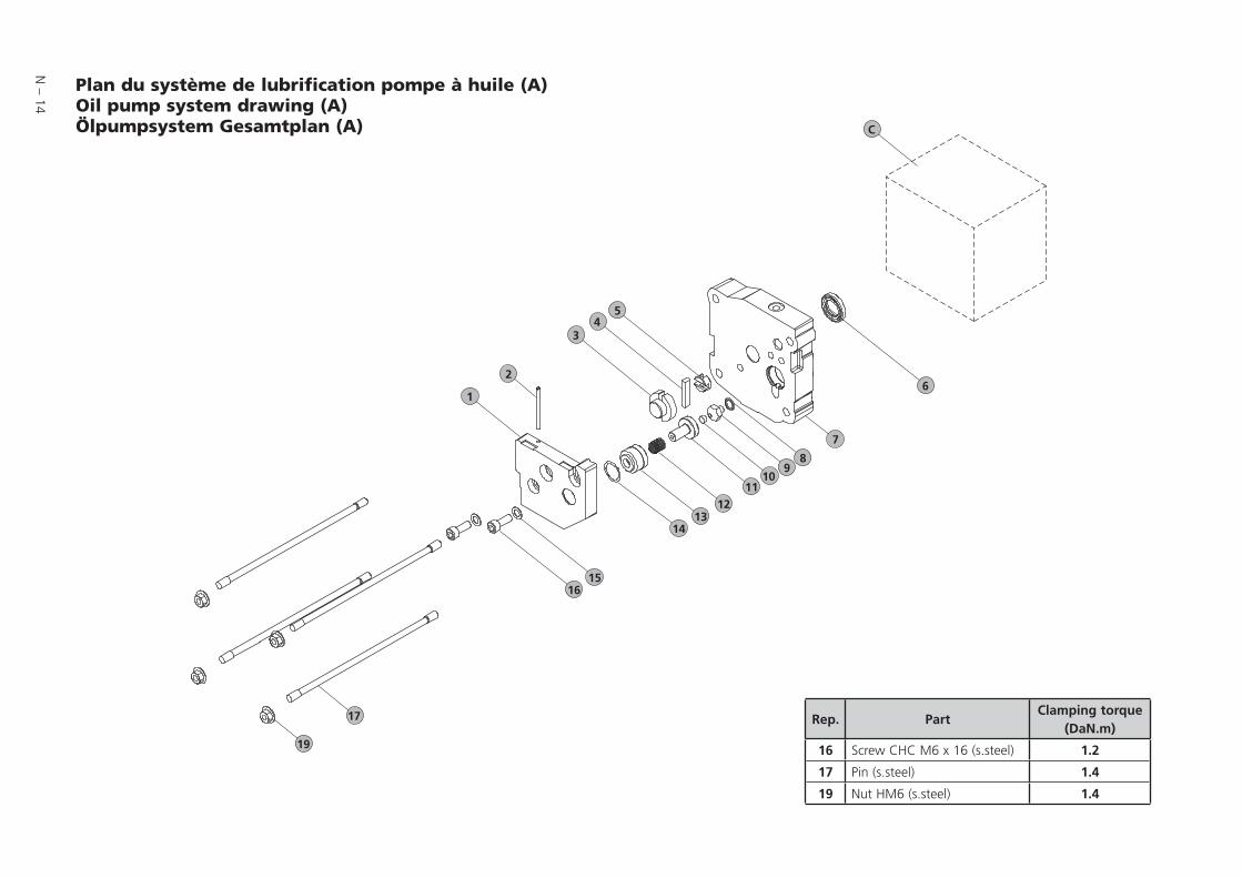
N – 14
14
17
19
12
6
1516
7
89
1011
3
1
2
45
13
C
Plan du système de lubrification pompe à huile (A)Oil pump system drawing (A) Ölpumpsystem Gesamtplan (A)
Rep. PartClamping torque
(DaN.m)
16 Screw CHC M6 x 16 (s.steel) 1.2
17 Pin (s.steel) 1.4
19 Nut HM6 (s.steel) 1.4

N – 15
Nomenclature
REP DÉSIGNATION SPECIFICATION BENENNUNG
Types/modelREF.P/N
Bestell. Nr2005
I
2010
I
2015
I
2021
I
1015
SD
1021
SD
2010
C2
2015
C2
2021
C2
2005
C1
2010
C1
2015
C1
2021
C1
1005
C1
1010
C1
1015
C1
1021
C1
1 Couvercle pompe à huile Oil pump cover Ölpumpendeckel 1 1 1 1 1 1 1 1 1 1 1 1 1 1 1 1 1 1034162 Tube entrée d’air Air admission tube Lufteinlass 1 1 1 1 1 1 1 1 1 1 1 1 1 1 1 1 1 1043343 Rotor pompe à huile Oil pump rotor Ölpumpenrotor 1 1 1 1 1 1 1 1 1 1 1 1 1 1 1 1 1 1034124 Palette pompe à huile Oil pump vane Ölpumpenschieber 1 1 1 1 1 1 1 1 1 1 1 1 1 1 1 1 1 5 Joint de oldham Oldham coupling Oldhamring 1 1 1 1 1 1 1 1 1 1 1 1 1 1 1 1 1 1034136 Joint à lèvre 15 x 25,5 x 4,6 Shaft seal 15 x 25.5 x 4.6 Lippendichtung 15 x 25,5 x 4,6 1 1 1 1 1 1 1 1 1 1 1 1 1 1 1 7 Flasque arrière Rear plate Hintererflansche 1 1 1 1 1 1 A2154137 Flasque arrière Rear plate Hintererflansche 1 1 1 1 1 1 1 A2154147 Flasque arrière Rear plate Hintererflansche 1 1 1 1 1033988 Joint torique c 1,5 - d 7,5 O-ring c 1.5 - d 7.5 Dichtung c 1,5 - d 7,5 1 1 1 1 1 1 1 1 1 1 1 1 1 1 1 1 1 9 Siège Seat Sitz 1 1 1 1 1 1 1 1029099 Siège Seat Sitz 1 1 1 1 1 1 1 1 1 1 10338910 Clapet anti-retour Antisuck-back device Rückschlagventil 1 1 1 1 1 1 1 1 1 1 1 1 1 1 1 1 1 11 Piston anti-retour Antisuck-back piston Kolber 1 1 1 1 1 1 1 1 1 1 1 1 1 1 1 1 1 10296212 Ressort d’étanchéité Spring Feder 1 1 1 1 1 1 1 1 1 1 1 1 1 1 1 1 1 13 Cylindre anti-retour Oil pump antisuck-back cylinder Rückschlagzylinder 1 1 1 1 1 1 1 1 1 1 1 1 1 1 1 1 1 10296314 Rondelle élastique Spring washer Scheibe 1 1 1 1 1 1 1 1 1 1 1 1 1 1 1 1 1 15 Rondelle Washer Unterlegscheibe 2 2 2 2 2 2 2 2 2 2 2 2 2 2 2 2 2 16 Vis CHC M6 x 16 Screw CHC M6 x 16 Schraube CHC M6 x 16 2 2 2 2 2 2 2 2 2 2 2 2 2 2 2 2 2 17 Goujon M6-106 / 12 Pin M6-106 / 12 Stift M6-106 / 12 4 10352417 Goujon M6-129 / 19 Pin M6-129 / 19 Stift M6-129 / 19 4 4 4 4 10285517 Goujon M6-142 / 12 Pin M6-142 / 12 Stift M6-142 / 12 4 4 4 06580617 Goujon M6-164 / 12 Pin M6-164 / 12 Stift M6-164 / 12 4 4 4 06580517 Goujon M6-187 / 12 Pin M6-187 / 12 Stift M6-187 / 12 4 4 4 06580417 Goujon M6-72 / 19 Pin M6-72 / 19 Stift M6-72 / 19 4 06563617 Goujon M6-84 / 12 Pin M6-84 / 12 Stift M6-84 / 12 4 10352217 Goujon M6-106 / 12 Pin M6-106 / 12 Stift M6-106 / 12 4 10352419 Ecrou à embase HM6 Shoudered nut HM6 Schraubenmutter HM6 4 4 4 4 4 4 4 4 4 4 4 4 4 4 4 4 4
Lot joints / Minor kit / Dichtungssatz Lot maintenance / Major kit / Wartungssatz Lot visserie / Screw kit / Schraubensatz Lot palettes pompe à huile / Oil vane pump kit / Ölpumpenschieberssatz
Nomenclature du système de lubrification pompe à huile / Oil pump system part list / Ölpumpsystem Nomenklatur
Sous-ensemble A / Subassembly A / Gesamtplan A

N – 16
11
14
16
9
1213
67
8
4
12
3
5
10
C
Plan du système de lubrification levier moulinet (B)Oil system drawing (B)Ölpumpsystem Gesamtplan (B)
Rep. PartClamping torque
(DaN.m)
1 Screw CHC M6 x 16 (s.steel) 1.2
13 Screw CHC M6 x 10 (s.steel) 1.2
14 Pin (s.steel) 1.4
16 Nut (s.steel) 1.4

N – 17
Nomenclature
REP DÉSIGNATION SPECIFICATION BENENNUNG
Types/modelREF.P/N
Bestell. Nr
2005
SD
2010
SD
2015
SD
2021
SD
1005
SD
1015
SD
1 Vis CHC M6 x 16 Screw CHC M6 x 16 Schraube CHC M6 x 16 2 2 2 2 2 2 2 Rondelle Washer Unterlegscheibe 2/3 2/3 2/3 2/3 2/3 2/3 3 Levier oscillant Equipped lever Hebel 1 1 1 1 1 1 4 Flasque arrière Rear plate Hintererflansche 1 1 1 1 A2154124 Flasque arrière Rear plate Hintererflansche 1 1 1034855 Joint à lèvre 15 x 25,5 x 4,6 Shaft seal 15 x 25.5 x 4.6 Lippendichtung 15 x 25,5 x 4,6 1 1 1 1 1 1 6 Came moulinet Impeller Flügelnocke 1 1 1 1 1 1 0527217 Bague d’arrêt Clips Sprengring 1 1 1 1 1 1 8 Rondelle Washer Unterlegscheibe 1 1 1 1 0527588 Gicleur Jet Düse 1 1 1029109 Joint torique c 1,9 - d 5,7 - Bague R5 O-ring c 1.9 - d 5.7 - Ring R5 Dichtung c 1,9 - d 5,7 - Ring R5 1 1 1 1 1 1 10 Siège de clapet Seat Ventilsitz 1 1 1 1 1 1 05271811 Bride Flange Klammer 1 1 1 1 1 1 05256912 Idem 2 Idem 2 Ebenso 2 1/3 1/3 1/3 1/3 1/3 1/3 13 Vis CHC M6 x 10 Screw CHC M6 x 10 Schraube CHC M6 x 10 1 1 1 1 1 1 14 Goujon M6-129 / 19 Pin M6-129 / 19 Stift M6-129 / 19 4 10285514 Goujon M6-142 / 12 Pin M6-142 / 12 Stift M6-142 / 12 4 06580614 Goujon M6-164 / 12 Pin M6-164 / 12 Stift M6-164 / 12 4 06580514 Goujon M6-187 / 12 Pin M6-187 / 12 Stift M6-187 / 12 4 06580414 Goujon M6-72 / 19 Pin M6-72 / 19 Stift M6-72 / 19 4 06563614 Goujon M6-84 / 12 Pin M6-84 / 12 Stift M6-84 / 12 4 10352216 Ecrou à embase HM6 Shoudered nut HM6 Schraubenmutter HM6 4 4 4 4 4 4
Lot joints / Minor kit / Dichtungssatz Lot maintenance / Major kit / Wartungssatz Lot visserie / Screw kit / Schraubensatz
Nomenclature du système de lubrification levier moulinet / Oilsystem part list / Ölpumpsystem Nomenklatur
Sous-ensemble B / Subassembly B / Gesamtplan B

N – 18
1
2
5
3
4
1a
Plan ensemble motorisation (M)Motor assembly drawing (M) Motor Gesamtplan (M)
Rep. PartClamping torque
(DaN.m)
5 Screw CHc M6 x 40 (s.steel) 1.1
2 Screw Hc M6 x 8.8 (s.steel) 0.8

N – 19
Nomenclature
Nomenclature ensemble motorisation (M) / Motor assembly part list (M) / Motor Gesamtheit Nomenklatur (M)
MOTEUR UNIVERSEL / UNIVERSAL MOTOR / UNIVERSELLE MOTOR
REP DÉSIGNATION SPECIFICATION BENENNUNG QtyREF.P/N
Bestell. Nr1 Moteur monophasé standard avec interrupteur* Single phase motor with on/off switch* Wechselstrommotor* mit Shalter 1 1086941 Moteur monophasé sans interrupteur* Single phase motor without switch* Wechselstrommotor* ohne Shalter* 1 1086981 Moteur triphasé standard Three-phase motor Drehstrommotor 1 108695
1a Kit d’adaptation pour moteur bride CEI (bride CEI + vis + 1/2 manchon + intercalaire)
CEI flange motor coupling kit (CEI flange + screw +motor side coupling+ plastic coupling)
CEI Klammer Motorflanschssatz (Klammer Motorflanschssatz + Schraube +Kupplugshälfte + Küpplungsstern) 1 104558
1b Kit d’adaptation pour moteur bride Nema (bride Nema + vis + 1/2 manchon US + intercalaire)
Nema flange motor coupling kit (Nema flange + screw +US motor side coupling+ plastic coupling)
Nema Klammer Motorflanschssatz (Klammer Motorflanschssatz + Schraube +US Kupplugshälfte + Küpplungsstern) 1
105952
2 Vis Hc M6 x 8,8 Screw Hc M6 x 8.8 Schraube Hc M6 x 8,8 1 3 1/2 Manchon moteur Motor side coupling Kupplungshälfte 1 0657424 Intercalaire Plastic coupling Kupplungstern 1 5 Vis CHc M6 x 40 Screw CHc M6 x 40 Schraube CHc M6 x 40 4
* Moteur livré sans câble mais équipé avec 2+3+4 * Delivered without cable but equipped with 2+3+4 * ohne Netzkabel aber mit 2+3+4 einrichtet
Lot joints / Minor kit / Dichtungssatz Lot maintenance / Major kit / Wartungssatz Lot visserie / Screw kit / Schraubensatz
CÂBLE ÉLECTRIQUE POUR MOTEUR MONOPHASÉ / ELECTRICAL CABLE FOR SINGLE PHASE MOTOR / NETZKABEL FÜR WECHSELSTROMMOTOR (L = 2M)
DÉSIGNATION SPECIFICATION BENENNUNGREF.P/N
Bestell. NrUSA (Basse tension) USA (Low voltage) Netzkabel (Niederspannung) (USA) 103567USA (Haute tension) USA (High voltage) Netzkabel (Hochspannung) (USA) 103898EUROPE EUROPE Netzkabel (EUROPA) 103566JAPON (Basse tension) JAPAN (Basse tension) Netzkabel (Niederspannung) (JAPAN) 103567JAPON (Haute tension) JAPAN (Haute tension) Netzkabel (Hochspannung) (JAPAN) 104559ROYAUME UNI UNITED KINGDOM Netzkabel (GB) 104411SUISSE (Coudé) SWITZERLAND (elbow) Netzkabel (SCHWEIZ) A459212
Des moteurs spéciaux sont disponibles sur demande (anti-déflagrant…)Specific motors are available on request (Explosion-proof…)
Spezialmotore (z.B. explosionsgeschützt) sind auf Anfrage erhältlich

N – 20
8
9
7
12
3
45
6
C
BA or
Plan du système bulleurBubbler system drawingBubbler system Gesamtplan
Nomenclature du système bulleur / Bubbler system part list / Bubbler system Nomenklatur
REP DÉSIGNATION SPECIFICATION BENENNUNG
Types/modelREF.P/N
Bestell. Nr
2010
C2
2015
C2
2021
C2
1 Bouchon 1/8 NPT Plug 1/8 NPT Blindstopfen 1/8 NPT 1 1 1 0829262 Manchon Coupling Kupplung 1 1 1 0658663 Ruban teflon Teflon band Teflon band 1 1 1 0609754 Bille inox 18/8 d. 5,8 Ball 18/8 d. 5.8 Kugel 18/8 d, 5,8 1 1 1 0875935 Ressort Spring Feder 1 1 1 0651496 Raccord G 1/8 -1/8 NPT Connector G 1/8 -1/8 NPT Verbindungselement 1 1 1 0658677 Joint torique c 1,9 - d 7,2 O-ring c 1.9 - d 7.2 Dichtung c 1,9 - d 7,2 1 1 18 Bulleur Bubbler Bubler 1 1 0658368 Bulleur Bubbler Bubler 1 0658359 Attache tube Tube fastener Rohrbefestigung 1 1 1 065835
Lot joints / Minor kit / Dichtungssatz Lot maintenance / Major kit / Wartungssatz Lot visserie / Screw kit / Schraubensatz


CHINAAlcatel Vacuum Technology, ShanghaiN°82 Lane 887 Zuchongzhi RoadZhangjiang High-Tech Park,Shanghai 201203 ChinaTel. (86) 21 5027 0628Fax. (86) 21 3895 3815
FRANCEAlcatel Vacuum Technology France98, avenue de Brogny - BP 206974009 Annecy cedexFranceTel. (33) 4 50 65 77 77Fax. (33) 4 50 65 77 89
GERMANYAlcatel Hochvakuumtechnik GmbHAm Kreuzeck 10 - Postfach 115197877 Wertheim GermanyTel. (49) 9342 9610 0Fax. (49) 9342 9610 30
ITALYAlcatel Vacuum SystemsVia Trento, 3020059 Vimercate (Mi) ItalyTel. (39) 0396 86 38 55Fax. (39) 039 66 71 25
JAPANAlcatel-Lucent Japan Ltd.1-9-4 Kita Shin-YokohamaKohoku-kuYokohama, Kanagawa 223-0059JapanTel. (81) 3 6431 7130Fax. (81) 45 544 0049
KOREAAlcatel Vacuum Technology Korea447 Banwol-dong, Hawsung-si,445-330 Kyungki-do,South KoreaTel. (82) 031-206-6277Fax. (82) 031-204-6279
NETHERLANDSALCATEL Vacuum Technology Benelux Landzichtweg 60NL 4105 DP CulemborgThe NetherlandsTel. (31) 345 478 400Fax. (31) 345 531 076
SINGAPOREAlcatel-Lucent Singapore49 Jalan Pemimpin#01-02 APS Industrial Building577203SingaporeTel. (65) 6254 0828Fax. (65) 6254 7018
SWEDENAdixen Sensistor AB.Box 76 SE-581 02 LinköpingSweden Tel. 46 (0)13 35 59 00Fax. 46 (0)13 35 59 01
TAIWANAlcatel Vacuum Technology TaïwanNo. 169-3, Sec.1, Kang-Leh RdSong-Lin Village, Hsin-Feng 304Hsin-Chu CountyTaïwan - R.O.C.Tel. (886) 3 559 9230Fax.(886) 3559 9231
UNITED KINGDOMAlcatel Vacuum Technology UK Ltd8 Bain Square - Kirkton CampusLivingston - West LothianEH54 7DQ - ScotlandUnited KingdomTel. (44) 1 506 418 000Fax. (44) 1 506 418 002
USAAlcatel Vacuum Products67, Sharp StreetHingham - MA 02043USATel. (1) 781 331 4200Fax. (1) 781 331 4230
Alcatel Vacuum Technology France98, avenue de Brogny - BP 2069 - 74009 Annecy cedex - FRANCE - Tel. (33) 4 50 65 77 77 - Fax. (33) 4 50 65 77 89
Web site: www.adixen.com
An Alcatel-Lucent Company