passenger vehicle tire pressure monitoring system … · 1. product introduction thanks for...
TRANSCRIPT

Internal , External Sensor
Passenger Vehicle
Tire Pressure Monitoring System
Instruction Manual
CL201

SO Sensor
CL201 Monitor
Product Picture1. Product Introduction
2. Special Feature
3. Product Assembly
4. Installation Instruction
5. Parameter Setting
01
SS Sensor
SU Sensor
SN Sensor
SI Sensor
6. Monitor Parameter Display
7. Alarm Status
7-5.Senor Low voltage alarm
7-1.High Pressure Alarm
7-2.Low Pressure Alarm
7-3.High Temperature Alarm
7-4.Fast air leakage alarm
8. Custom ID coding
9. Sensors Installation
9-1.SS External Sensor
9-2.SI Internal Sensor
9-3.SU External Sensor
9-4.SN External Sensor
9-5.SO External Sensor
10. Technical Specifications
11. Friendly Reminder
02
02
04
04
06
06
06
07
07
07
08
08
09
09
11
14
15
17
19
20

1. Product Introduction
Thanks for choosing our TPMS products. The system is used to monitor the pressure and
temperature of each tire. Once alarming condition is set up by the user, the system will alarm in
case of abnormal pressure and temperature to make the driver be alerted of any danger .
The system also enhance fuel efficient, prolong tire life and to make the driving more comfortable.
Be sure to read the user guide carefully before installation and keep the manual for future use.
It is highly recommended to read the instructions below before install the system:
(2) The vehicle should be stopped for cooling if there is high temperature alarm in order to
avoid braking problem or tire blowout.
(3) Driver should stop the vehicle and get off to check the tire if there is continue high
pressure or slow leakage alarm .
(4) Be ware of tire blowout when there is high tire pressure, and be ware of fuel consumption
and wheel balance while low tire pressure.
(5)The system can effectively monitor tire pressure and temperature but cannot avoid all
traffic accident or tire blowout. Using quality tire product and monitor correct tire pressure
is still necessary.
(6) Be ware of driving safety while checking tire data during driving.
(7) After the system is installed correctly, the driver does not need to stare at the monitor
all the time and feel interrupt during driving.
1-1 Production Introduction
1-2. SAFETY CAUTION
1-3. INSTALLATION TIPS
1.The signal transmission from the monitor and sensors is wireless, and the transmission
distance is long enough for a passenger car due to internal anti-inference circuit design.
2.Due to the air expansion and contraction, the tire pressure and temperature will normally
changing all the time while driving.
3.There is normal air leakage in every tire rim, TPMS should have no responsibility to keep
the tire pressure unchanged after long time storage or driving.
4.Should you have any question or problem while installation, please contact with your
local distributor.
Tire Pressure Monitoring System
(1) The monitor should be installed inside the vehicle where it does not affect driving visibility.
01

2. Special Features
• Pressure, Temperature Alarm
• Visual & Audible Alarm
• Fixed Pressure, Temperature alarm level setting
• Tire setting Interchangeable
• Multiple measurement scale (PSI/BAR)
• 4 wheel display at the same time
• Fast leakage alert
• Easy installation, stable performance
3. Product Assembly
3-1 Display Key and LCD diagram
① LCD Screen
② “SET” Key
③ Full Character Display
Pressure unit BAR/PSI
Temperature ºC only
2
3
1
ICON Description
Alarm Status
Sensor Battery Low
Tire Pressure Monitoring System
02

SS Sensor
SU Sensor
SN Sensor
SI Sensor
SO Sensor
3-2. Product Accessories
Hex Nut Ribber O-Ring
Opener Tool
Hex Driver
Hex Wrench
Hex Wrench
(1pcs)
Quantity of will be shipped in 4 pieces or specified by customer to add one more pieces at extra cost.
Sensor for spare
Receiver Parts
Sensor accessories
Enclosure details refer to actual product
screw
(4pcs) (4pcs)
Hex Nut Ribber O-RingHex Wrench
(1pcs) (4pcs) (4pcs) (1pcs)
Opener Tool
(1pcs)
Ribber O-Ring
(4pcs) (1pcs)
Opener Tool
(1pcs)
Hex Nut Ribber O-RingHex Wrench
(1pcs) (4pcs) (4pcs)
(1pcs)
Tire Pressure Monitoring System
(4pcs)
03

Design of this monitor is to use cigarette lighter adaptor (CLA) power for easier installation and avoid any obstacle to driver view. Please plug in the CLA firmly to begin the normal mode operation and upon power up through CLA.
4-1. Monitor Display Installation
Tips:1.When reading the data form the monitor shall need additional safety awareness.2.The purpose of this monitor is to allow alarm to the driver on time and no need driver’s attention during driving.
4. Installation Instruction
5. Parameter Setting
Selection of pressure unit (PSI or BAR) can be done by user, details as below:
Under normal condition, press “SET” key for 3 seconds until “Bi “sound to release, system will
begin SETUP mode, press on flashing unit once will allow changing to another unit, upon selection
of preference unit, press “SET” again for 3 second until “Bi” sound to release will resume normal
mode and save the changes. If nothing was pressed during SETUP mode for one minutes, system
will also return to normal mode but without saving changes.
5-1 Pressure unit selection
mount position
Tire Pressure Monitoring System
Flashing
04

During normal mode operation, long press “SET” key for 3 second until “Bi” sound to release, system will enter initial setup mode for pressure units with flashing icon, press “SET” key for 1 second will change to high (UP) pressure alarm level setup mode, short press “SET” key to scroll to preference pressure value, press “SET” key for another 1 second will change to low (d0) pressure alarm level set up mode. Short press “SET” key to scroll to preference pressure value. Upon selection of above UP/d0 alarm level, Long press “SET” key until “Bi” sound to release and save the changes. If nothing was pressed during setup mode for one minutes, system will also return to normal mode but without saving changes.
5-2. High/Low pressure alarm level setting
Flashing
Press SETFor 1 sec
During normal mode operation, long press “SET” key for 3 second until “Bi” sound to release,
system will enter initial setup mode for pressure units with flashing icon, press “SET” key for
1 second will change to high (UP) pressure alarm level setup mode and press “SET” key to
next 1 second will change to low (d0) pressure alarm level set up mode. press “SET” key for
next “1” second to enter temperature setup mode. Short press “SET” key to scroll preference
temperature value. Upon selection of above temperature alarm level, Long press “SET” key
until “Bi” sound to release and save the changes. If nothing was pressed during setup mode
for one minutes, system will also return to normal mode but without saving changes.
5-3. Temperature alarm level setting
Press SETFor 1 sec
Flashing
SUMMARY: Pressure Unit/ High Pressure value/Low pressure Value/High Temperature value setup sequence as below:
Press SETFor 1 sec
Flashing Flashing
Press SETFor 1 sec
Press SETFor 1 sec
Tire Pressure Monitoring System
05

6. Monitor Parameter Display
Display can show 4 wheels Pressure & Temperature together:
During monitor displayed pressure, press ”SET” once will change to temperature reading for 10 seconds and resume previous pressure reading.
10 seconds
Display has design to use same user interface to show 4 wheels pressure & temperature reading together, when tire pressure excess its preset alarm limits, display will indicate corresponding alarm icon ( , ) through flashing and sound. Press ”SET” once will stop the alarm sound , the flashing icon can only be stopped when tire problem can physically be resolved.
e.g. Left Front tire pressure reached 3.1BAR, display showing alarm together with (Bi…Bi…Bi…) sound as shown.
Factory default alarm setting:
7. Alarm Status
7-1. High Pressure Alarm
High Pressure/ Low Pressure/ High Temperature/ Fast Leakage/ Sensor Low Battery alarm
High Pressure Alarm level 3.0BAR (44 PSI)
Low Pressure Alarm level 2.0BAR (29 PSI)
High Temperature Alarm level o 70 C
Pressure Reading flashing
Alarm Status icon flashing
Tire Pressure Monitoring System
06
Step to restore factory default setting: press and hold SET key and plug the console into the cigarette lighter power socket until Bi sound to confirm factory setting was restored.

e.g. Left Front tire pressure reached 1.9BAR, display showing alarm together with (Bi…Bi…Bi…) sound as shown.
oe.g. Left Front tire pressure reached 71°C,
display showing alarm together with (Bi…Bi…Bi…) sound as shown
7-2 Low Pressure Alarm
7-3 High Temperature Alarm
Pressure Reading flashing
Alarm Status icon flashing
Once sensor has detected fast leakage will signal to monitor immediately, pressure reading, and alarm icon will flashing together, alarm (Bi…Bi… BI…) will sound. Press ”SET” once will stop the alarm sound , the flashing icon can only be stopped when tire problem can physically be resolved.
e.g. Left Front tire pressure dropped from
2.4BAR to 2.1 BAR, fast leakage display as
shown.
7-4 Fast Leakage Alarm
Pressure Reading flashing
Alarm Status icon flashing
Pressure Reading flashing
Alarm Status icon flashing
Tire Pressure Monitoring System
07
Low battery icon flashing
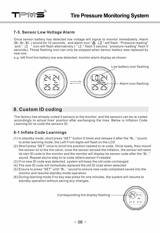
Once sensor battery has detected low voltage will signal to monitor immediately. Alarm (Bi..BI..BI..) sound for 10 seconds, and alarm icon “ , “ will flash. “Pressure reading” and “ “ icon will flash alternatively ( “ “ flash 3 second, “pressure reading” flash 5 seconds). Those flashing icon can only be stopped when sensor battery was replaced by new one.
e.g. left front tire battery low was detected, monitor alarm display as shown:
7-5. Sensor Low Voltage Alarm
Alarm icon flashing
The factory has already coded 4 sensors to the monitor, and the sensors can be re-coded accordingly to actual tires’ position after exchanging the tires. Below is Inflation Code Learning for re-code the sensors ID:
8-1 Inflate Code Learnings
Corresponding tire display flashing
(1) In standby mode, short press “SET” button 5 times and release it after the “Bi..” sound to enter learning mode, the Left Front digits will flash on the LCD (2) Short press “SET” once to scroll tire position needed to re-code. Once ready, then mount the sensor on to the tire valve, once the sensor sensed the inflation, the sensor will send its own ID code to the monitor and the monitor will display he sensor code after the “Bi..” sound. Repeat above step to re-code others sensor if needed .(3) If no new ID code was detected, system will keep the old code unchanged. (4) The new ID code will immediate replaced the old ID code when detected(5) Ensure to press “SET” until “Bi..” sound to ensure new code completed saved into the monitor and resume standby mode operation. (6) During learning mode if no key was press for one minutes, the system will resume to standby operation without saving any changes.
8. Custom ID coding
Tire Pressure Monitoring System
08

3hex nut
9-1. SS External Sensors Installation:
1air valve
Tips:1. Please mount the sensor in position according to label mark.2. Low voltage alarm will appear when sensor battery voltage is low.3. After mounting all sensors, please double check if there is air leakage by using soapy water in air intake.
Fix the hexagon nuts in tire valve.
Fasten sensor to the tire air valve.
Use special wrench to tight hexagonal nuts in counter clockwise direction.
hex nut
sensor2
9. Sensors Installation:
Notice: please ensure to turn on the monitor firstly before install the sensor so that the monitor can receive the sensor data on time.
Tips: Please mount sensors based on Factory default position. If there are error coding or wrong tire position, please read “recode sensor session” before restart.
Default Mounting Position
The factory has already set up the codes to each tire position .The standards are 4 sensors with one monitor, and every sensors marked tire’s position with: LF, LR, RF, RR with stickers. If there is spare tire in customers’ car, so it’s needed to mark it’s position with stickers. Please stick the correct tire position for easier future reference .
LF
LR RR
RF
Tire Pressure Monitoring System
09

(2) Use Special Wrench to turn Hex Nuts counter clockwise and unscrew the sensor by special Wrench in counter clockwise.
(5) check if the rubber O-ring is in good condition otherwise replace a new one.
Open or fasten the sensor battery cover with special opener tools. Please
(3) Use the hex wrench provided to remove the water proof cover from sensor.
(4) Replace new CR1632, (+) terminal upward.
CR 1632 Lithium Battery
CR1632
Rubber O-ring
8-2. SS Sensor battery replacement
When the sensor low battery icon shows on the monitor and corresponding tire icon is flashing, the sensor battery needs replacement. Using CR1632 battery cell which operates at -40oC to +80oC is recommended. You can buy replacement batteries from your local dealer.
(1) Remove senor from tire rim
unfasten hex nuts in clock wise direction
Unmount senor in counter clock wise direction
sensorhex nut
Tire Pressure Monitoring System
"-" "+"CR 1632 Lithium Battery
10

Remove complete wheel from Car, remove rubber tire from wheel, remove original tire valve from wheel and replace by the internal tire sensor valve to corresponding tire position (i.e. Left Front, Left Rear, Right Front, Right Rear). Cross check if washer and hexagonal nuts provide in the tire sensor valve has been mounted outside the wheel, reinstall rubber tire, inflate tire to standard pressure and balance the wheel then remount the complete wheel back to the car.
Tips: During Rubber tire removal, please to avoid operation at 15cm circular space above the top of sensor and be ware of broken the sensor accidentally.
(1) Remove complete wheel from car before deflation,(2) Use tire remover to remove rubber tire and cut out the original tire valve,
tire remover
air valve
old air valve removed
sensor air valvewasher
nuts dust cover
(3) Remove all washer, nuts , dust cover from sensor air valve
(4) Use specific tool (wrench) provided to loosen or tuning the nuts position.
Special wrenchPlease keep for future removal use
9-2 SI internal sensor installation
Tips: Before installation of sensors, please be sure to turn on the monitor in order to capture the data timely.
Tire Pressure Monitoring System
11

(6) Take out the senor assembly from the wheel and use special wrench to lock the air valve position on sensor.
Special wrench
(5) Remove all washer, nuts , dust cover from sensor air valve. Get ready the special wrench for new air valve installation.
best angle
(7) Remove all washer, nuts , dust cover from sensor air valve
Dust cover
nuts
metal washer
Tips: tighten the sensor position by only hand force and avoid sensor side to lying on the wheel.
Tire Pressure Monitoring System
12

Inflate tire
Sensor mounted
Tips:1. Above sensor installation should be done by professional or trained technician2. Need to pay attention to sensors mount position all the time aware of potential damage to the sensor.3. Each senor are labeled with its wheel position and highly recommended to be used during installation4. Once sensor battery is low, monitor display will have sign for low battery alarm.5. After all sensor has been installed, please ensure no any air leakage over wheel surface and may use soapy water for testing if necessary.
(8) Upon mounting of rubber tire wheel, inspect any damage to the sensor, all parts in right position or any sight of air leakage. Doing any wheel balance and mount the wheel back to the car
Tire Pressure Monitoring System
13

Tips:1. Each senor are labeled with its wheel position and highly recommended to be used during installation2. If battery inside sensor has insufficient voltage will trigger battery low alarm 3. After all sensor has been installed, please ensure no any air leakage over wheel surface and may use soapy water for testing if necessary.
9-3 SU sensor installation
(1) Use fixture provided inside package and open the plastic enclosure in counter clockwise direction
(2) remove battery from battery holder
(3) replace new lithium battery CR1225 with “+ve” polarity upside
Locking cover
BatteryOpener tools
C R12253VSC
SU Sensor battery replacement
Tips: please be sure to turn on the monitor first before installation of sensor.
Screw in sensor at clock wise direction
sensor3
Tighten hex nuts in counter clock wise direction
Hex nut 4
Mount the hex nuts
1
Check if locking cover is in place
2Air valve
Hex nut
Tire Pressure Monitoring System
CR 1225 Lithium Battery "-" "+"
CR 1225 Lithium Battery
14

(4 ) remount plastic enclosure using the fixture provided in counter clockwise directionTips: Please inspect the rubber o-ring if being damage and replace by new one if needed.
Rubber O-ring
Mount concave plastic in line with convex position
Locate concave shape on sensor surface
(1) Remove dust cover from air valve intake.(2) Please mount the sensor in position according to label mark.(3) After mounting all sensors, please double check if there is air leakage by using soapy water in air intake(4) Use hex key to lock the hex screw on to the air valve.
Notice: please ensure to turn on the monitor firstly before install the sensor so that the monitor can receive the sensor data on time.
*use hand force to tight the sensor in clockwise direction and avoid damage to the sensor. Use only specific hex key to counter lock or counter unlock the sensor position
Hex Driver
Screw
Tips :1.Please mount the sensor in position according to label mark.2. Low voltage alarm will appear when sensor battery voltage is low.3. After mounting all sensors, please double check if there is air leakage by putting soapy water in air intake.
9-4 SN External Sensors Installation:
Tire Pressure Monitoring System
15

When the sensor low battery icon shows on the monitor and corresponding tire icon isflashing, the sensor battery needs replacement. Using CR1632 battery cell which operates at -40ºC to +80ºC is recommended. You can buy replacement batteries from your local dealer
Tips: avoid confusion by label on battery door surface during battery replacement
(1) Use the hex wrench provided to remove the anti-theft screw and take out the sensor
(4) Replace the new Lithium CR1632, ensure the positive+ is facing upwards
+
CR1632
(3) Take out old battery
(2) Hold the sensor inside opener tools and open sensor cover in clockwise direction.
Opener tools
(5) Open or fasten the sensor battery cover with special opener tools. Replace new battery with correct polarity. Please check if the rubber O-ring is in good condition otherwise replace a new one.
Rubber O-ring
SN external sensor battery replacement
Tire Pressure Monitoring System
CR 1632 Lithium Battery "-" "+"
CR 1632 Lithium Battery
16

3Hex nut
1Air valve
Hex nut
sensor2
Tips:1. Each senor are labeled with its wheel position and highly recommended to be used during installation2. If battery inside sensor has insufficient voltage will trigger battery low alarm 3. After all sensor has been installed, please ensure no any air leakage over wheel surface and may use soapy water for testing if necessary.
9-5. SO External Sensors Installation:
Notice: please ensure to turn on the monitor firstly before install the sensor so that the monitor can receive the sensor data on time.
1
2
3
Tire Pressure Monitoring System
Fix the hexagon nuts in tire valve.
Fasten sensor to the tire air valve.
Use special wrench to tight hexagonal nuts in counter clockwise direction.
17
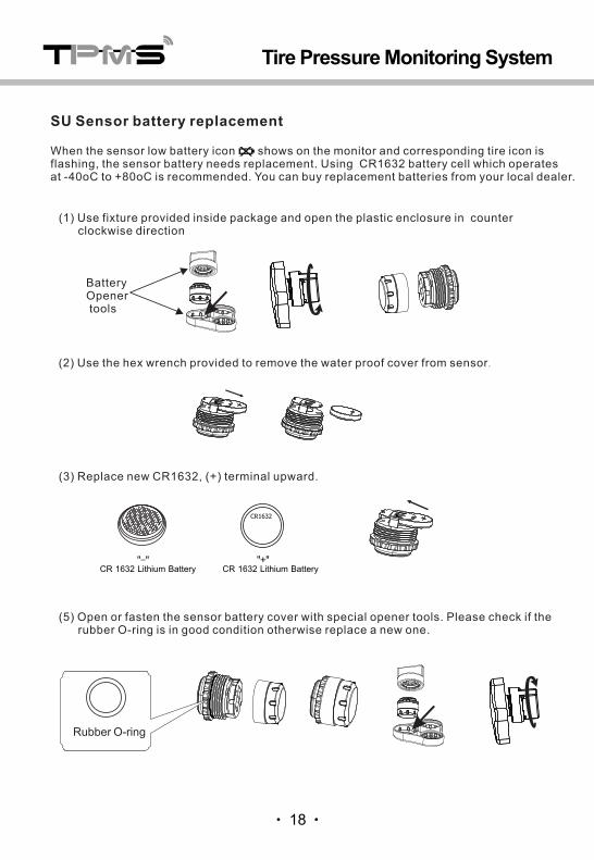
(3) Replace new CR1632, (+) terminal upward.
+ CR1632
(5) Open or fasten the sensor battery cover with special opener tools. Please check if the rubber O-ring is in good condition otherwise replace a new one.
When the sensor low battery icon shows on the monitor and corresponding tire icon is flashing, the sensor battery needs replacement. Using CR1632 battery cell which operates at -40oC to +80oC is recommended. You can buy replacement batteries from your local dealer.
SU Sensor battery replacement
(2) Use the hex wrench provided to remove the water proof cover from sensor.
(1) Use fixture provided inside package and open the plastic enclosure in counter clockwise direction
BatteryOpener tools
Tire Pressure Monitoring System
CR 1632 Lithium Battery "-" "+"
CR 1632 Lithium Battery
Rubber O-ring
18

0~6 bar (0~87 psi )
<10dBm
433.92MHz
≥ Yrs2
3 oC
1.5 psi ( 0.1 bar )
-40 +85o oC~ C
-40 +80o oC~ C
9 g
21 ( )X17.7 mm Φ (H)
<10dBm
433.92MHz
≥3 Yrs
o o-40 C ~ 85 C
o o-40 C ~ 80 C
48 g
60 x 35 x 21mm
0~8 bar (0~116 psi )
3 oC
1.5 psi ( 0.1 bar )
≥3 Yrs
9 g
0~6 bar (0~87 psi )
<10dBm
433.92MHz
3 oC
1.5 psi ( 0.1 bar )
-40 +85o oC~ C
-40 +80o oC~ C
SS sensor
0~6 bar (0~87 psi )
<10dBm
433.92MHz
≥ Yrs2
3 oC
1.5 psi ( 0.1 bar )
-40 +85o oC~ C
-40 +80o oC~ C
9 g
≥2 Yrs
6 g
0~6 bar (0~87 psi )
<5dBm
433.92MHz
3 oC
1.5 psi ( 0.1 bar )
-20 +85o oC~ C
-20 +80o oC~ C
10. Technical Specification
33 ( Φ) 5 0 ( H)mm x
20 g
Working temperature
10.1 Monitor Specification
21 ( )X21 mm Φ (H)
21 ( )X17.5 mm Φ (H) 18 ( )X13 mm Φ (H)
Tire Pressure Monitoring System
19
10.2 Sensor Specification
Storagetemperature
OutputVoltage
Frequency
Size
Weight
Working temperature
Storagetemperature
PressurerangePressureAccuracy
TemperatureAccuracyTransmissionPower
Transmission
Battery life
Dimenson
Weight
SI sensor SN sensor
SO sensor SU sensor
Working temperature
Storagetemperature
PressurerangePressureAccuracy
TemperatureAccuracy
TransmissionPower
Transmission
Battery life
Dimenson
Weight

11. Friendly reminder
(1) Please use the system correctly in the right condition. Our company is not liable for
damages from the miss-use.
(2) Installation should follow the instruction guide, if any damage occurs due to the wrong
installation, our company is not liable for it.
(3) The content and specification are subject to change without prior notice. Pictures in the
article are just for illustration. Please take the actual product for reference.
(4) Internal sensor installation should be carried out by professional person. Be ware of the
internal sensors while reload the tire.
20
Tire Pressure Monitoring System