passively damped laminated piezoelectric shell structures ... · passively damped laminated...
TRANSCRIPT
NASA/CR--1999-208871
Passively Damped Laminated Piezoelectric
Shell Structures With IntegratedElectric Networks
Dimitris A. Saravanos
Ohio Aerospace Institute, Cleveland, Ohio
Prepared under Cooperative Agreement NCC3-455
National Aeronautics and
Space Administration
Glenn Research Center
March 1999
https://ntrs.nasa.gov/search.jsp?R=19990052892 2018-08-22T12:13:05+00:00Z

Acknowledgments
This work was performed at the Machine Dynamics Branch, Structures and Acoustics Division of
NASA Glenn Research Center and was funded by NASA cooperative agreement NCC3-455.
Mr. Dale A. Hopkins was the contract monitor. This support is gratefully acknowledged.
This report is a preprint of a paper intended for presentation at a conference. Because
of changes that may be made before formal publication, this preprint is made
available with the understanding that it will not be cited or reproduced without thepermission of the author.
NASA Center for Aerospace Information7121 Standard Drive
Hanover, MD 21076
Price Code: A03
Available from
National Technical Information Service
5285 Port Royal Road
Springfield, VA 22100Price Code: A03
PASSIVELY DAMPED LAMINATED PIEZOELECTRIC SHELL
STRUCTURES WITH INTEGRATED ELECTRIC NETWORKS
Dimitris A. Saravanos*
Ohio Aerospace Institute22800 Cedar Point Road
C_eveland, Ohio 44142
SUMMARY
Multifield mechanics are presented for curvilinear piezoelectric laminates interlaced with distributed passive
electric components. The equations of motion for laminated piezoelectric shell structures with embedded passiveelectric networks are directly formulated and solved using a finite element methodology. The modal damping and
frequencies of the piezoelectric shell are calculated from the poles of the system. Experimental and numerical results
are presented for the modal damping and frequency of composite beams with a resistively shunted piezoceramic
patch. The modal damping and frequency of plates, cylindrical shells and cylindrical composite blades with piezo-
electric-resistor layers are predicted. Both analytical and experimental studies illustrate a unique dependence of
modal damping and frequencies on the shunting resistance and show the effect of structural shape and curvature on
piezoelectric damping.
INTRODUCTION
The continuous requirements imposed on many new structural applications for improved vibroacoustic response
and weight reduction mandate the development of new damping concepts. Embedded piezoelectric layers introduce
the unique capability to convert strain energy to electric energy during a vibration cycle and vice-versa. By connect-
ing passive electric networks of resistors and capacitors to the piezoelectric layers, a fraction of electric energy may
be dissipated or spontaneously stored, thus increasing the damping and changing the natural frequencies of the struc-
ture. Compared to other techniques which typically introduce high damping, for example, the constrained
interlaminar viscoelastic layer and active damping techniques, the passive piezoelectric damping may exhibit very
desirable characteristics, such as: capability to be modified, spontaneously or periodically, by varying the properties
of the passive electric elements (resistors, capacitors, etc.); damping improvement may not decrease laminate stiff-
ness, as is the case with viscoelastic damping layers; and the required hardware is minimal and may be even encap-sulated into the laminate, thus adding minimal weight to the structure. Consequently, the approach may be very
suitable for damping vibrations in rotating or moving components, such as turbomachinery blades, helicopter blades,and so forth.
While substantial work has been reported in the area of active vibration control as described in recent reviews
(refs. 1 to 2), most of the reported work on passive piezoelectric damping has been limited to simple laminate and
structural (mostly beam and plate) configurations. Hagood and Von Flotow (ref. 3) first studied analytically and
experimentally the use of passive piezoelectric elements to dampen beam structures. Law et al. (ref. 4) have reported
simplified models and experimental results for piezoelectric materials shunted by a load resistor. Davis and
Lesieutre (ref. 5) predicted the passive damping of beams with resistively shunted piezoelectric patches based on the
strain energy dissipation approach, and reported experimental results. Koshigoe and Murdock (ref. 6) reported a
simplified analytical formulation for plates with passive piezoelectric elements. Wang et al. (ref. 7) have reported
work on a semi-active vibration control approach for beams with piezoelectric elements combining passive electric
components with an active controller concept. Yarlagadda et al. (ref. 8) presented micromechanics and experimental
results for composites with resistively shunted pJezoceramic fibers. Saravanos (tel: 9) devel_ped an exact in-plane
Ritz formulation for the prediction of damping in composite plates with resistively shunted piezoelectric elements.
'Senior Research Associate.
NASA/CR-- 1999-208871 I
Whilethereportedworkhasprovidedvaluableinsightregardingthepotentialofpassivepiezoelectricdamping,developmentofefficientmethodologiesenablingthepredictionofdampinginrealisticlaminateandstructuralcon-figurationsisstillrequired.Thispaperpresentsmulti-fieldmechanicsforcurvilinearcompositelaminateswithpiezoelectriclayershavingdistributedpassiveelectriccomponentsembeddedorattachedtothepiezoelectriclayers,andanassociatedshellfiniteelementforpredictingthemodaldamping,mtxtalfrequenciesanddynamicresponseofdampedpiezoelectricshells.Thelaminatemechanicscombinesingle-layerkinematicassumptionsforthedisplace-mentswitha layerwisevariationoftheelectricpotential.Theformulationdirectlyconsidersthepresenceofdistrib-utedelectricnetworks,thusenablingcoupledandefficientrepresentationsoftheintegratedlaminate-electriccircuitsystem.Governingequationsofmotionaredevelopedandsolvedinstate-spacetorm.Thepolesofthecoupledstructuralsystemarecalculatedandusedtoevaluatethemodaldampingandfrequenciesoftheshellstructure.Thefrequencyresponseofthedampedstructureisalsodirectlycalculatedfromtheequationsofmotion.
DOUBLYCURVEDPIEZOLAMINATESWITHPASSIVEELECTRICNETWORKS
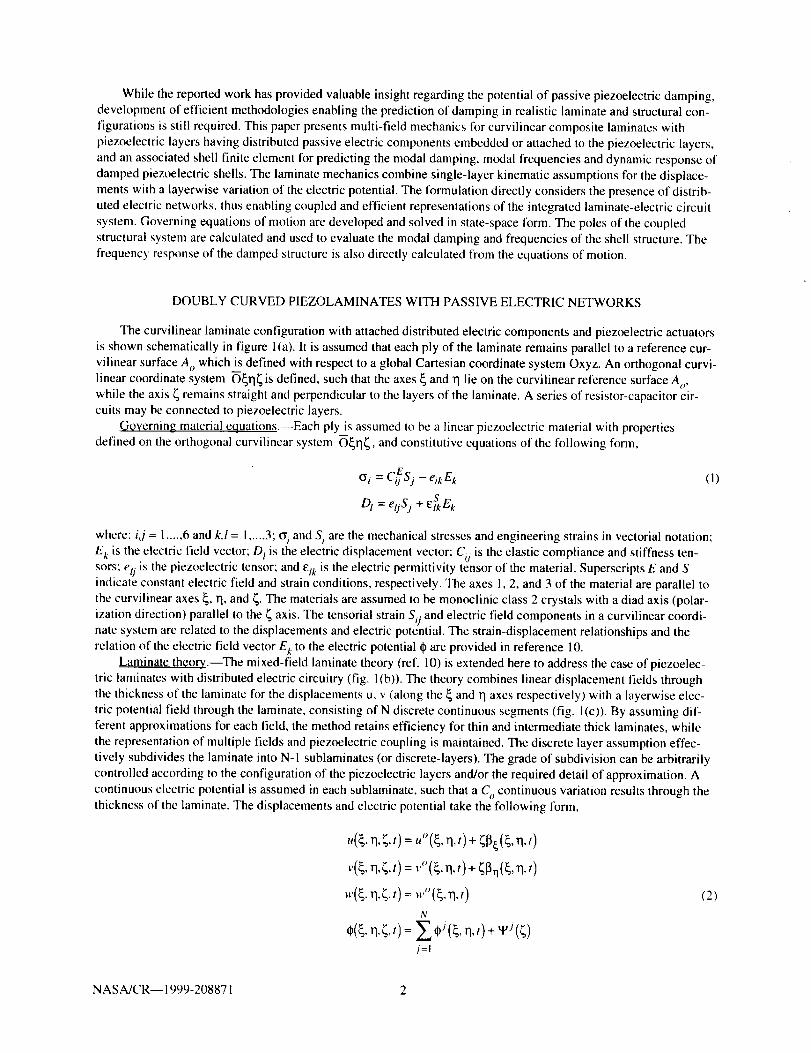
Thecurvilinearlaminateconfigurationwithattacheddistributedelectriccomponentsandpiezoelectricactuatorsisshownschematicallyin figurel(a).It isassumedthateachplyofthelaminateremainsparalleltoareferencecur-vilinearsurfaceA o which is defined with respect to a global Cartesian coordinate system Oxyz. An orthogonal curvi-
linear coordinate system O_rl_ is defined, such that the axes _ and rl lie on the curvilinear reference surface A o,while the axis _ remains straight and perpendicular to the layers of the laminate. A series of resistor-capacitor cir-cuits may be connected to piezoelectric layers.
Governing material equations.--Each ply is assumed to be a linear piezoelectric material with properties
defined on the orthogonal curvilinear system O_rl_, and constitutive equations of the following form,
E0 i = Ci) Sj - elk E k
D I = eoS j + _S_Ek
(I)
where: i,j = 1..... 6 and k,l = I ..... 3; _i and S i are the mechanical stresses and engineering strains in vectorial notation;
E t is the electric field vector: D! is the electric displacement vector; Cij is the elastic compliance and stiffness ten-
sors; etj is the piezoelectric tensor; and etk is the electric permittivity tensor of the material. Superscripts E and Sindicate constant electric field and strain conditions, respectively. The axes 1, 2, and 3 of the material are parallel to
the curvilinear axes _, rl, and 4- The materials are assumed to be monoclinic class 2 crystals with a diad axis (polar-
ization direction) parallel to the _ axis. The tensorial strain SO and electric field components in a curvilinear coordi-nate system are related to the displacements and electric potential. The strain-displacement relationships and therelation of the electric field vector E k to the electric potential _ are provided in reference 10.
Laminate theory.--The mixed-field laminate theory (ref. 10) is extended here to address the case of piezoelec-
tric laminates with distributed electric circuitry (fig. 1(b)). The theory combines linear displacement fields throughthe thickness of the laminate for the displacements u, v (along the _ and I1 axes respectively) with a layerwise elec-
tric potential field through the laminate, consisting of N discrete continuous segments (fig. I(c)). By assuming dif-
ferent approximations for each field, the method retains efficiency tbr thin and intermediate thick laminates, while
the representation of multiple fields and piezoelectric coupling is maintained. The discrete layer assumption effec-
tively subdivides the laminate into N-1 sublaminates (or discrete-layers). The grade of subdivision can be arbitrarily
controlled according to the configuration of the piezoelectric layers and/or the required detail of approximation. A
continuous electric potential is assumed in each sublaminate, such that a C continuous variation results through thethickness of the laminate. The displacements and electric potential take the following form,
,a.;,,)=." q,,)+ n,,)
v(_,rl,_,t) = v°(_,rl, t) + ;_.q(_, q,t)
N
n.¢,,)= n.t)+w(¢)j=l
(2)
NASA/CR-- 1999-208871 2

whereu°, v°, w" are displacements along the _, q and _ axes, respectively, on the reference surface Ao; superscript j
indicates the points _J at the beginning and end of each discrete layer; _ is the electric potential at each point _J (see
fig. I(c)); tpj (z) are interpolation functions; and 13_,13qare the rotation angles,
_4'_ + u" w{'q v"
gll Rt g22 R2
(3)
where R i are the local radii of curvature (fig. l(a)); g_l' g_2 are the components of the metric tensor for the referencesurface.
Equations of motion.--The variational statement of the equations of motion for a piezoelectric laminate with
assumed displacement and electric potential fields takes the form (ref. 10):
(4)
where A, is the curvilinear reference surface, z and D overbar are the surface tractions and electric displacement
acting respectively on boundary surfaces F._, 1-',; 8H L and 5T L are the variations of the electric enthalpy and kinetic
energy of the laminate, defined as,
h o o
<8HL'STL> = _0 (SH'ST>g'lg22d;(5)
and h is the laminate thickness. The electric enthalpy of the piezoelectric laminate is a quadratic expression of the
generalized strain/electric field and the generalized laminate matrices (ref. 10),
N
,, ,, o 6kjE'j E 3 +BE 3 Ej kj)_)H L = _)S_ aijs ) +_)SjBijkj+_)kjBjiS[' +_kiDijkj -_'_(_c°EmEmZ._woiik k + _Ekm--mEki S}° + ^,,, m m^m
N N
-Z Z e;'G i=1 i=1
(6)
In the above equation, [A], [B], and [D] are the stiffness matrices of the curvilinear laminate, [E m] overbar and
overhat are the piezoelectric matrices, and [G rim] are the laminate matrices of electric permittivity. L is the number
of plies in the laminate. The kinetic energy of the laminate takes the torm,
_)TL e o A .o ,, B" +_)_jpBt'lj + ==OUiP i Ui +SUjpj_j _)_jpDfjj, i I ..... 3, j=!,2(7)
where u"i-- {u"'v°'w°} and 13i ={ _, _rl}; pA, pB, pD are the generalized densities, expressing the mass, mass couplingand rotational inertia per unit area, respectively, of the laminate.
Electric circuitry._Considering that a passive electric circuit with resistive and capacitive elements is inter-faced to the terminal surfaces nt and n (see fig. l(b)) of the piezoelectric laminate, the electric potential f and electric
flux _ in the circuit are related as follows,
(8)
NASA/CR-- 1999-208871 3
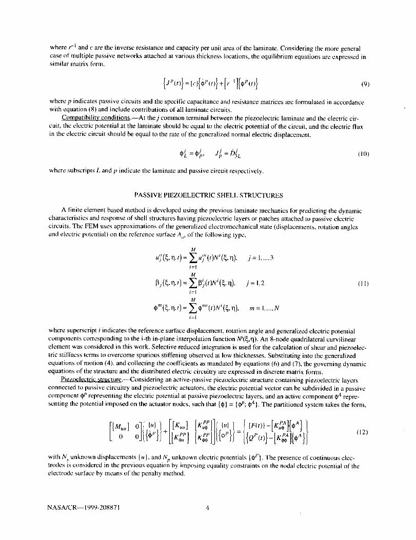
wherer-l and c are the inverse resistance and capacity per unit area of the laminate. Considering the more general
case of multiple passive networks attached at various thickness locations, the equilibrium equations are expressed insimilar matrix form,
(9)
where p indicates passive circuits and the specific capacitance and resistance matrices are formulated in accordance
with equation (8) and include contributions of all laminate circuits.
Compatibility conditions.--At thej common terminal between the piezoelectric laminate and the electric cir-
cuit, the electric potential at the laminate should be equal to the electric potential of the circuit, and the electric flux
in the electric circuit should be equal to the rate of the generalized normal electric displacement.
where subscripts L and p indicate the laminate and passive circuit respectively.
PASSIVE PIEZOELECTRIC SHELL STRUCTURES
A finite clement based method is developed using the previous laminate mechanics for predicting the dynamic
characteristics and response of shell structures having piezoelectric layers or patches attached to passive electric
circuits. The FEM uses approximations of the generalized electromechanical state (displacements, rotation angles
and electric potential) on the reference surtace Ao, of the following type,
M
idol _. x oi ij t_' 11,t) = Z uj (t)N (_, 1"1), j = 1..... 3i=1M
_j(_,rl, t)=Z_.(t)Ni(_,q), j=l,2i=1
M
Cm(_,rl, t)=___¢mi(t)Ni(_,q), m=l ..... Nu
i=1
(11)
where superscript i indicates the reference surface displacement, rotation angle and generalized electric potential
components corresponding to the i-th in-plane interpolation function Ni(_,rl). An 8-node quadrilateral curvilinear
element was considered in this work. Selective reduced integration is used for the calculation of shear and piezoelec-
tric stiffness terms to overcome spurious stiffening observed at low thicknesses. Substituting into the generalized
equations of motion (4), and collecting the coefficients as mandated by equations (6) and (7), the governing dynamic
equations of the structure and the distributed electric circuitry are expressed in discrete matrix forms.
Piezoelectric structure.--Considering an active-passive piezoelectric structure containing piezoelectric layers
connected to passive circuitry and piezoelectric actuators, the electric potential vector can be subdivided in a passive
component _t, representing the electric potential at passive piezoelectric layers, and an active component _ repre-senting the potential imposed on the actuator nodes, such that {_} = {¢[_P;_y4}. The partitioned system takes the form,
Mo,,,]olf I,,ll ilK.,,]+,..,,.,L"*_ J
['_s'll;_,.,.1 I {F(t)}--[KuP_A]{+A} I
[K_P ]J ].t_b 1' tl = {{QP(t)}-IK;_]{+A}J
(12)
with Ns unknown displacements {u}, and Np unknown electric potentials {_P}. The presence of continuous elec-trodes is considered in the previous equation by imposing equality constraints on the nodal electric potential of theelectrode surlace by means of the penalty meth_xt.
NASA/CR-- 1999-208871 4
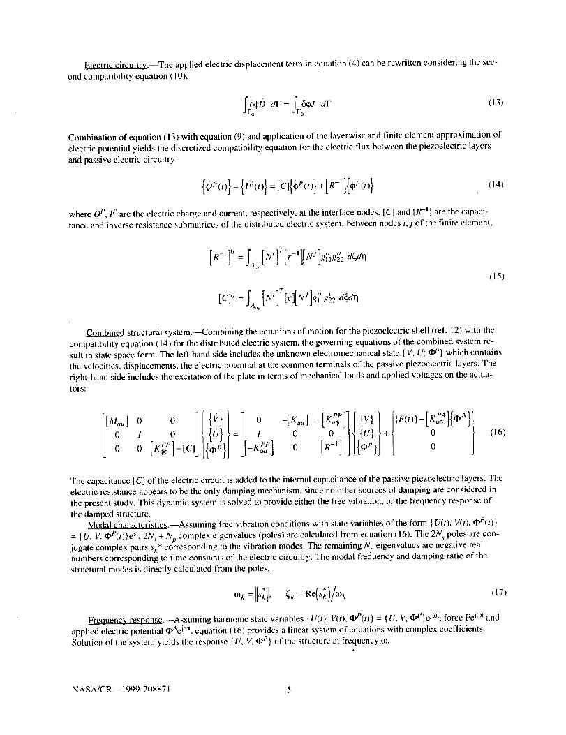
Electriccircuitry.--Theappliedelectricdisplacementterminequation(4)canberewrittenconsideringthesec-ondcompatibilityequation(I0),
Combinationofequation(13)withequation(9)andapplicationofthelayerwiseandfiniteelementapproximationofelectricpotentialyieldsthediscretizedcompatibilityequationlbrtheelectricfluxbetweenthepiezoelectriclayersandpassiveelectriccircuitry
{Qp(t)}={,P(t)} =[C]{(pP(t)}+[R-II{_P(t)} (14)
whereQP, 1p are the electric charge and current, respectively, at the interface nodes. [C] and [R -I] are the capaci-
tance and inverse resistance submatrices of the distributed electric system, between nodes i,j of the finite element,
(15)
Combined structural system.--Combining the equations of motion for the piezoelectric shell (ref. 12) with the
compatibility equation (14) for the distributed electric system, the governing equations of the combined system re-sult in state space form. The left-hand side includes the unknown electromechanical state {V; U; (l_'} which contains
the velocities, displacements, the electric potential at the common terminals of the passive piezoelectric layers. The
right-hand side includes the excitation of the plate in terms of mechanical loads and applied voltages on the actua-tors:
[M,,,,] 0 0
, oo [,,::]-IcJ[{q] [[ 0 -tK..lo0 /t 0
[R-'] J [{,x,r}] t o
(16)
The capacitance [C] of the electric circuit is added to the internal capacitance of the passive piezoelectric layers. The
electric resistance appears to be the only damping mechanism, since no other sources of damping are considered in
the present study. This dynamic system is solved to provide either the free vibration, or the frequency response of
the damped structure.Modal characteristics.IASsuming free vibration conditions with state variables of the form {U(t), V(t), qbP(t)}
= { U, V, _P(t) }est, 2N s + Np complex eigenvalues (poles) are calculated from equation (16). The 2N s poles are con-jugate complex pairs sk* corresponding to the vibration modes. The remaining Np eigenvalues are negative realnumbers corresponding to time constants of the electric circuitry. The modal frequency and damping ratio of the
structural modes is directly calculated from the poles,
Frequency response.--Assuming harmonic state variables {U(t), V(t), qbP(t)} = { U, V, _P}e jr°t, lbrce Fe j°_l and
applied electric potential ¢_AeJ°_, equation (16) provides a linear system of equations with complex coefficients.Solution of the system yields the response {U, V, qbt'} of the structure at frequency _0.
g
NASA/CR-- 1999-2(.)8871 5

CASESTUDIES
Variousnumericalstudieswereperformedinordertoevaluatetheaccuracyandconvergenceofthedevelopedformulation,including:(I)comparisonswithmeasureddampingandfrequencydataofcompositebeamswithanattachedpiezoceramic-resistorpatch,and(2)convergencestudiestowardsexactRitzin-planesolutionsforspecialtyplatesandcylindricalpanelswithdistributedpiezoelectric-resistorlayers.Thepiezoelectricdampingofclamped-freecylindricalcompositebladeswithdiscretepiezoelectric-resistorpatcheswasalsoinvestigated.
Materials and assumpti0n_;.--The properties of all materials are shown in table I. The T300/934 Graphite/epoxycomposite was used for all composite laminates in this work. Composite beam specimens of this material were also
fabricated and tested. A PZT-4 piezoceramic was considered in all numerical examples. PZT-4 patches provided by
American Piezoceramics International (material APC 840) were used in the fabrication of the beam specimens.
0LQ4/9_2.Q40_. Cantilever beam.--A 104/9041s T300/934 Graphite/Epoxy beam, 234 mm long and 25.4 mm wide,with a surface epoxied PZT-4 patch having a variable resistor attached on its surface terminals was fabricated and
tested. The beam was supported in cantilever configuration, and the modal characteristics were measured and also
predicted using the developed shell finite element. Figure 2 shows the geometry and testing configuration of the
beam. The direction of fibers in the 0° plies was parallel to the beam axis, the thickness of each composite ply was
0.262 mm, while the thickness of the piezoceramic patch was 0.762 mm. The size of the piezoceramic patch was
50.8 by 25.4 ram, and the lower electrode was wrapped around the free-edge and covered 2 mm of the upper surfaceto provide space for wiring (see fig. 2).
The beam was impacted with an instrumented hammer and the acceleration was measured using a 0.50 graccelerometer, at the location shown in figure 2. The electric signals from the impact hammer and accelerometer
were acquired and digitized using a PC based dynamic data acquisition card and software. The frequency response
functions were calculated from the impact response data using FFT software. The poles of the beam were subse-
quently estimated using the method of complex exponentials. A model transfer function consisting of a series of
conjugate pairs of complex exponential terms (each pair corresponding to a mode) was correlated to the measured
frequency response function until the least-squares error was minimized. The modal frequency and damping were
subsequently calculated from the poles of the model system and they were assumed to approximate closely themodal damping and frequency values of the tested beam. Alter each measurement, the resistance was varied and
measured, and the test was repeated.
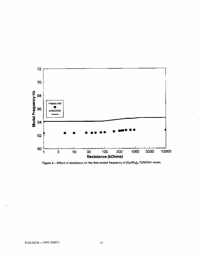
The measured damping increment and natural frequency of the first mode of the beam for various resistance
values are shown in figures 3 and 4. The damping increment was calculated from the measured damping at resis-
tance R by substracting the measured damping at open circuit conditions (R = oo) which was considered to represent
the baseline damping of the beam. The same figures also show the predicted values using a 14×1 nonuniform meshof the shell finite element. The presence of continuous electrodes was also modeled. The mass of the accelerometer
was tbund to affect the dynamics of the beam and was included into the finite element model. Both measured and
predicted damping and frequency values follow the same trends and are within reasonable agreement. The finite
element predictions seem to overestimate the measured data. The lower measured values are attributed to the pres-
ence and compliance of the adhesive layer (whereas the present formulation assumes a perfect bond) and possibledegradation of the actual piezoelectric coefficients than the ones provided by the manufacturer and used in themodel.
Figures 3 and 4 illustrate that there is an optimal resistance where damping reaches a maximum and frequency
shifts to a higher value. Beyond this optimal resistance value, the resistor and the capacitance of the piezoelectric
layer effectively tbrm a low-pass filter on the electric current flowing through the resistor. The cut-off frequency is
related to the resistance and capacitance of the piezoelectric layers. When the cut-off frequency exceeds the fre-
quency of a specific vibration mode, the electric flux through the resistor decreases and a fraction of electric flux is
stored in the piezoelectric capacitor during a vibration cycle. This decreases the dissipation of electric energy at the
resistor, and thus lowers the damping. As the bulk of electric energy remains stored in the piezoelectric capacitor,
the elastic strain energy of the beam is reduced resulting in higher natural frequencies.
Simply supported plate.--A simply supported [p/0/90/90/0/p] cross-ply Graphite/Epoxy composite square plate
is considered, with surface attached distributed piezoceramic (PZT-4) layers grounded at the inner surface and each
shunted with equal distributed resistance per unit area r. The nominal thickness of each composite ply was
tI = 0.375 mm and of each piezoelectric layer was tt, = 0.250 ram, thus, resulting in total plate thickness h = 2 ram.
NASA/CR-- 1999-208871 6
Thefreelengthoftheplatealongthex andy axeswasL_lh = L_lh = 157. Considering the two planes of symmetry,
only a quarter of the plate was modeled using a uniform mesh. Figure 5 shows the damping and natural frequency
predictions of the fundamental mode using various mesh densities, together with an exact in-plane Ritz solutionbased on the same laminate assumptions (ref. 9). Both damping and natural frequency predictions converge rapidly
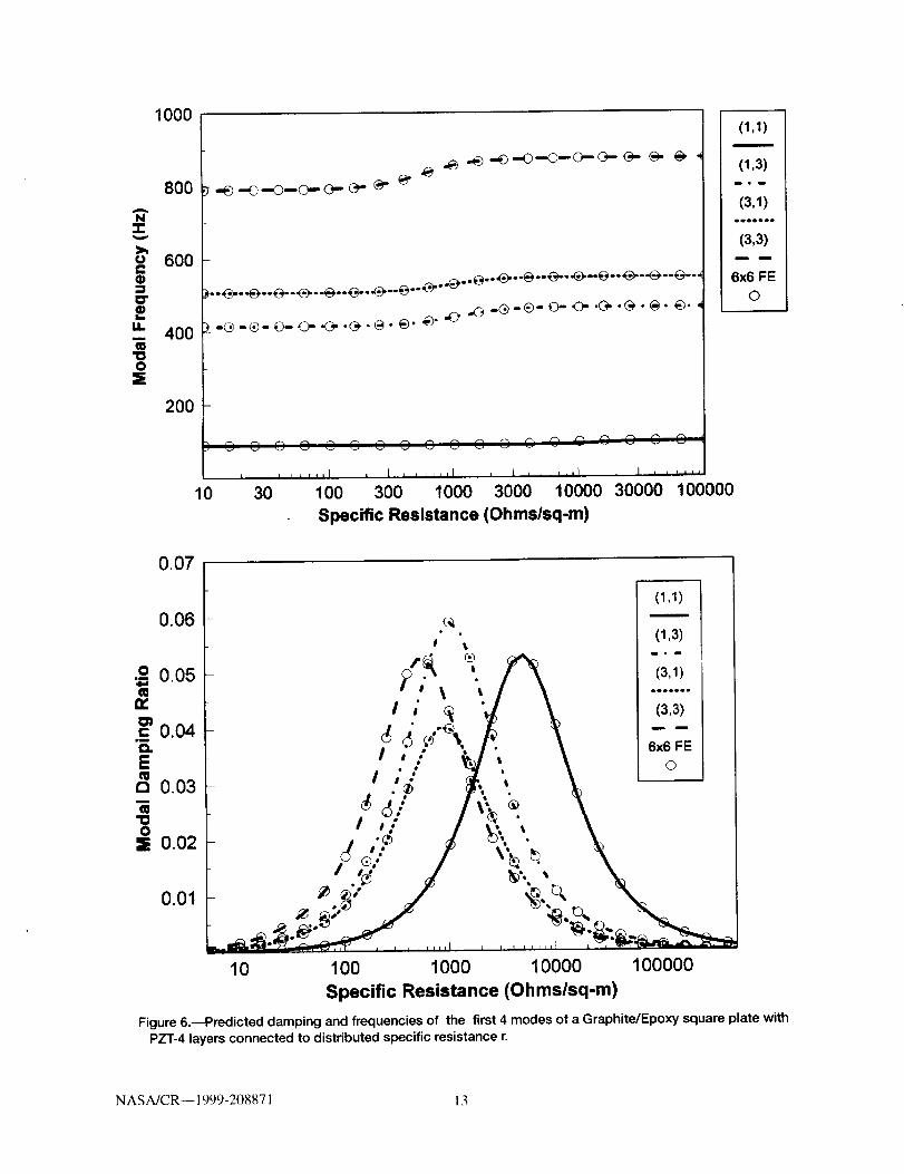
to the exact in-plane solution. As in the previous example, there is an optimal resistance where damping reaches amaximum and frequency shifts to a higher value. Figure 6 shows the damping of additional modes evaluated using a
6×6 uniform mesh. Besides the good agreement between the FE and exact solution, the results show that as the
modal frequency increases the corresponding damping peak occurs at lower resistance.
Simply-supported cylindrical panel.--The simply supported cylindrical quarter panel shown in figure 7 is con-
sidered. The panel has identical Gr/Epoxy [p/0/90] s laminate configuration, ply thicknesses and materials with the
previous case, with the 0° plies aligned along the hoop direction. Each PZT-4 layer is shunted with a distributed
resistance per unit area r. The length of the panel along the hoop (_) and axial (1"1)axes is L_/h = Lqlh = 157. Takinginto consideration the symmetry in axial direction, only one-half of the panel was m_deled usmg a unitbrm mesh.
Figure 8 shows the damping and frequency of the first mode which in this case is mode (3,1). The numbers in
parenthesis indicate the wavelengths along the hoop (_) and axial (rl) direction. Both damping and frequency predic-tions seem to rapidly converge towards an exact in-plane solution, although higher element subdivisions are required
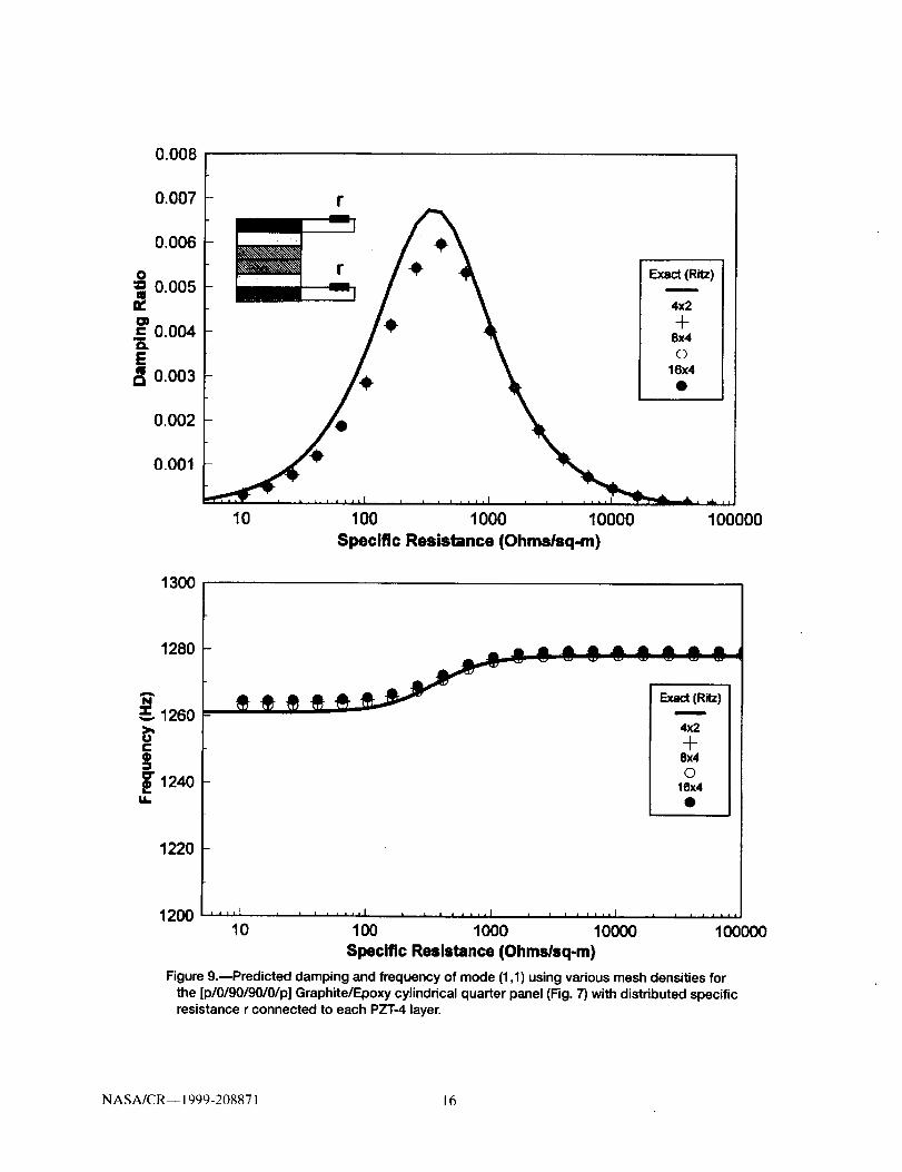
along the circumferential direction. Figure 9 shows the predicted damping and frequency corresponding to mode
shape ( I, 1 ) which occurs at a higher natural frequency, as a result of stiffening from extension-bending coupling
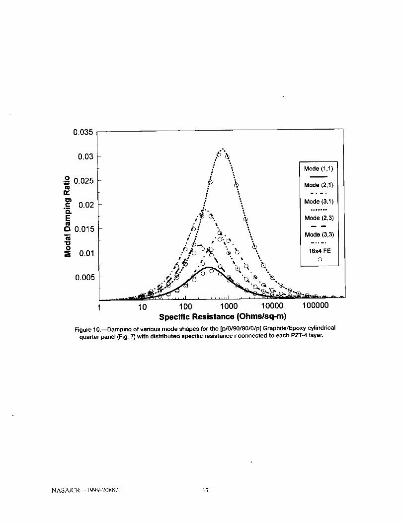
introduced by the curvature. The finite element predictions seem to converge to slightly different values from theRitz solution. Figure 10 shows damping predictions for the first 5 modes, and the very good overall agreement
between a 16×4 FE mesh and an in-plane exact Ritz method developed by the author. All modes illustrate the famil-
iar pattern of a maximum damping peak and shifting in the natural frequency with increasing resistance values.However, the prevailing difference with the previous plate case is the wide variation between the damping peaks of
the various modes, with modes ( 1,1 ) and (3,1 ) having the lower and higher damping peak, respectively. Curvature
induced extension-flexure coupling seems to adversely affect the damping effectiveness of the piezoelectric layers,
as it reduces the flexural strain-energy stored and dissipated at the piezoelectric layers. Overall, the present and pre-
vious cases have demonstrated the accuracy and convergence rate of the developed approach.
CANTILEVER CYLINDRICAL PANEL WITH PIEZOELECTRIC PATCHES
The more realistic case of a [0/90/45/-45] s Graphite/Epoxy cylindrical quarter-panel having curved PZT-4
patches symmetrically attached on both sides was also considered (fig. I I ). The 0 ° plies are parallel to the x axis.
The thicknesses of each composite ply and PZT-4 patch are 0.375 and 0.500 mm, respectively, and.the length aspect
ratio was L_/Lrl = 2, Lq = 140 mm. The panel was clamped at the lower curved edge and free at all others, toresemble an untwisted cylindrical blade. The location of piezoelectric patches (shaded area) on each side and the
finite element mesh are shown in figure I 1. The surface terminals of each piezoceramic patch were assumed to beconnected to an individual resistor, however, the values of the resistors were selected such that the specific resis-
tance remained the same for all piezoceramic patches. The continuous electrodes were modeled using penalty equal-
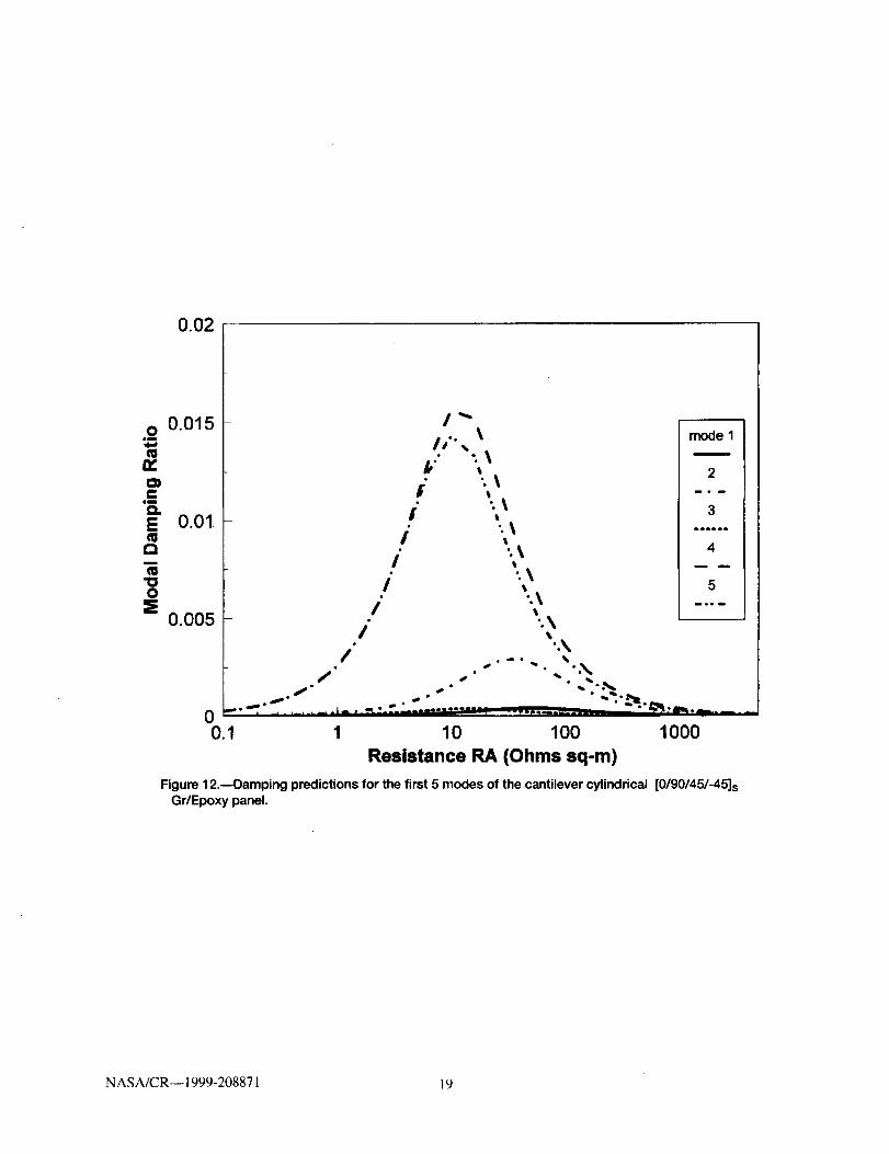
ity constraints on the surface electric potential.The predicted modal damping of the first five modes is shown in figure 12. Again the damping variation of each
mode follows the familiar peak pattern as the resistance increases, yet the modal damping varies widely betweenvarious modes. Because of the finite size and continuous electrodes of the piezoelectric patches, their location and
size become important parameters in connection with the respective mode shape. The present configuration seems tobe more effective with flexural modes (modes 2, 4 and 5) while provides minimal damping for twisting modes
( 1 and 3). The lower damping values, compared to previous cases of idealized distributed piezoelectric layers, are
attributed to the partial coverage of the surface by piezoelectric patches and the averaging of electric potential occur-
ring on each piezoceramic due to the finite size of their continuous electrodes. Besides demonstrating the extreme
capabilities of the developed methodology, the results show that the technique may yield substantial dampingincreases for select modes, provided that thc shunting resistance, size. and location of the piezoelectric layers is
properly designed. The value of the developed mechanics and finite element method in accomplishing such design
tasks is apparent.
NASA/CR-- 1999-208871 7

CONCLUSIONREMARKS
A formulationwasdescribedforpredictingthedampeddynamiccharacteristicsoflaminatedcompositeshellstructureswithpiezoelectriclayersconnectedtodistributedpassiveelectricnetworks.Theformulationincludesmultifieldmechanicsforcurvilinearpiezoelectriclaminateshavingdistributedpassiveelectriccomponents.Finiteelementbasedmechanicsandan8-nodespecialtyshellelementforpredictingthemodaldamping,modalfrequen-ciesanddampedresponseofpiezoelectricshellswerealsoformulatedandencodedintoresearchsoftware.
Experimentalandnumericalstudiesillustratedthequalityoftheformulationandquantifiedtheconceptofpas-sivepiezoelectricdampingonvariousstructuralconfigurations.Themodaldampingandfrequenciesofacompositebeamwithavariableresistor-piezoceramicelementweremeasuredandcorrelatedwithpredictedresults.Additionalcorrelationswithexactin-planesolutionsforplatesandshellsillustratedthefastconvergenceofthedevelopedfiniteelement•Themodaldampingandfrequencyofcylindricalcompositebladeswithresistivelyshuntedcurvedpiezo-
• .O , , .
electric patches were also predncted. All analytncal and experimental studnes have shown that regardless of the struc-
tural configuration: (i) the concept of passive piezoelectric damping is feasible, and (ii) the damping can be easilytuned by changing the resistance value and reaches a peak at a specific resistance value which differs for each node.
The shape of the structure seems to drastically affect the maximum damping value of each mode, with curvature
effects being predominant. The finite size and location of piezoelectric elements also seem to affect the damping ofeach mode. Application of the technique on complex structural configurations may require careful design consider-
ations. Overall, the results have illustrated the validity and effectiveness of the developed finite element formulation
for analyzing and designing passively damped piezoelectric structures.
REFERENCES
1. Crawley, E.F., 1994, "Intelligent Structures for Aerospace: A Technology Overview and Assessment,"
AIAA Journal, 32:8, pp. 1689-1699.
2. Rao, S.S. and Sunar, M., 1994, "Piezoelectricity and Its Use in Disturbance Sensing and Control of Flexible
Structures: A Survey," Applied Mechanics Reviews, 47:4, pp. II 3-123.
3. Hagood N. W. and von Flotow A. H., 1991, "Damping of Structural vibrations with piezoelectric materials andpassive electrical networks," Journal of Sound and Vibration, 146, pp. 243-268.
4. Law H.H.. Rossiter P.L., Simon G.P. and Koss L.L., 1996 "Characterization of Mechanical Vibration Dampingby Piezoelectric Materials," Journal of Sound and Vibration, 197:4, pp. 489-513.
5. Davis C.L. and Lesieutre G.A., 1995, "A Modal Strain-Energy Approach to the Prediction of ResistivelyShunted Piezoceramic Damping," Journal of Sound and Vibration, 184:1, pp. 129-139.
6. Koshigoe S• and Murdock J.W., 1993, "A Unified Analysis of Both Active and Passive Damping for a Platewith Piezoelectric Transducers.'" Journal of The Acoustical Society of America, 93:1, pp. 346--355.
7. Wang K.W., Lai J.S., Yu W.K., 1996, "An Energy Based Parametric Control Approach for Structural Vibration
Suppression via Semi-Active Piezoelectric Networks," Journal of Vibration and Acoustics, 118:3,
pp. 505-509.
8. Yarlagadda S., Lesieutre G.A., Yoshikawa S., Withnam J., 1996, "Resistively Shunted Piezocomposites for
Passive Vibration Damping," AIAA-96-1291-CP, 37th AIAMASME/ASCE/AHS/ASC SDM Conference
and Adaptive Structures Forum, Salt Lake City, UT, April 18-19, pp. 217-227.
9. Saravanos D.A. 1998, "Analysis of Damping in Composite Plates with Passive Piezoelectric-Resistor Ele-
ments," Journal of Sound and Vibration, in review, 1998.
10. Saravanos D.A., 1997, "Coupled Mixed-Field Laminate Theory and Finite Element 1or Smart Piezoelectric
Composite Shell Structures," AIAA Journal, Vol. 35:8. pp. 1327-1333.
NASA/CR--1999-208871 8
Elastic properties
Piezoelectric coefficients
(10 *-"m/V)
Electric permiltivity
Mass density p(kg/m_ )
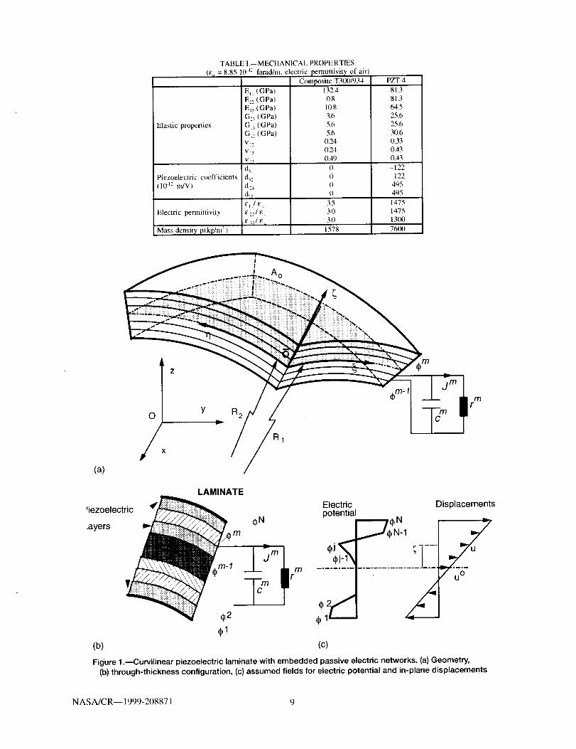
TABLE I.--MECHANICAL PROPERTIES
(EL/ = 8.85 10 l: farad/m, electric permittivit_' of air)
Composite T300/934
EI_ (GPa)
E:z (GPa)
E_3 (GPa)
G> (GPa)
GI_ (GPa)
GI, (GPa)
V12
Via
d_:d 2a
dls
CI1/E o
PZT4
132.4 81.3
0.8 81.310.8 64.5
3.6 25.65.6 25.6
5.6 N).60.24 0.33
0.24 0.43
0.49 0,43
0 -122
0 -122
0 495
0 495
3.5 1475
3.0 1475
3.0 131)0
1578 76(X)
O
/xY R 2
A o
a 1
mr
(a)
LAMINATE
Electric'iezoelectric potential
O N.ayers
m
Displacements
...............1....
(b) (c)
Figure 1 .---Curvilinear piezoelectric laminate with embedded passive electric networks. (a) Geometry,
(b) through-thickness configuration, (c) assumed fields for electric potential and in-plane displacements
NASA/CR-- 1999-208871 9

R
Piezoceramic
ImpactHammer
Accelerometer
95 _i124 _i
iI
234
25.4
v
Figure 2.--[04/904] s T300/934 cantilever beam with attached PZT-4 resistor patch. Side and top views.Dimensions in ram.
0.4
A
V
o,m
¢Dt.-
m
Q.Et_a
0.3
0.2
0.1
010 30 1O0 300
Resistance (kOhms)
measured
predictedm
1000 3000 10000
Figure 3.--Increase in the first mode damping of a [04/904] s T300/934 beam for various resistancevalues
NASA/CR-- 1999-208871 10
72
70
N
:2:68
ii
=E
62
measured
predicted
• oeOO • •
60 , I i liiill i ] i lilt11 i i ! , _,,,I
1 3 10 30 100 300 1000
Resistance (kOhms)
I I I = , , s
3000 10000
Figure 4.--Effect of resistance on the first modal frequency of [04/904]s T300/934 beam.
NASA/CR--1999-208871 I 1

0.06
0.05
o 0.04
(11r/,O_= 0.03D.EM
0 0.02
0.01
Exact (Ritz)
FE: lxl
2x2
O
4x4
O
6x6
X
10
115
100 1000 10000 100000
Specific Resistance (Ohmslsq-m)
1000000
110
105
_100o
M.
90
85
8O10
- Exact(Ritz)immmmm
FE: lxl
2x2
- 4X4 • •06x6 •
X
m • • • • • • • • • • •
i i I iiil[ i i i i i il P i i i i i Jill i i I _ I ,,,I. i i i J , q ,+
100 1000 10000 100000 1000000
Specific Resistance (Ohmslsq-m)
Figure 5.mFundamental modal damping and frequency using various mesh densities for a [p/0/90/90/0/p]Graphite/Epoxy square plate with PZT-4 layers connected to distributed specific resistance r.
N ASA/CR-- 1999-208871 12
AN
q-
¢J
D"Oi_
14.m
qDO=E
1000
800
600
400
200
._ -_-D -E> --O --O-- O-- @- (9- _"
10
I ...... I , [ ,, _,,,I , I = , L L=,i , i , .....
30 100 300 1000 3000 10000 30000 100000
Specific Resistance (Ohms/sq-m)
(1,1)
(I ,3)
(3,1)oe o°_°e
(3,3)
6x6 FE
O
007
006
.o 005
n,
,- 0.04Q.Eca,_ 003
"OO5 0.02
001
(I ,I)
(1,3)I %
_i i/ % .......
I ; <_ "4 k (3,3)
l;/o,<.k. \,d t
10 100 1000 10000 100000
Specific Resistance (Ohms/sq-m)
Figure 6.--Predicted damping and frequencies of the first 4 modes of a Graphite/Epoxy square plate with
PZT-4 layers connected to distributed specific resistance r.
NASA/CR-- 1999-208871 13

Figure 7._Cylindrical [plO/90190101p] Graphite/Epoxy, PZT-4 quarter panel.
N ASA/CR-- 1999-208871 14

0.035
0.03
0.0250
_' 0.02
CO.E 0.015
o
0.01
0.005
+
÷
÷
Exact (Ritz)
4x2
÷8x4
©16x4
o
900
10 100 1000 10000 100000
Specific Resistance (Ohmslsq-m)
850
8O0
N-r>, 750U
Q
o" 700
nlk
650
600
+++÷+++÷+÷+++÷++++÷- ÷+_
Exact (Ritz)
I i =11 i
10
m
4x2
÷8x4
©16x4
o
o o o o o OO O o o 0 o
o o oo o Oj "''''''''-o 00 _.........db. mh, _ db.
550 ....... i ........ , ........ _ ........ i1O0 1000 10000 100000
Specific Resistance (Ohmslsq-m)
Figure 8.--Predicted damping and frequency of first frequency mode (3,1) using various mesh densities
for the [plOI9019010/p] Graphite/Epoxy cylindrical quarter panel (Fig. 7) with distributed specific re-
sistance r connected to each PZT-4 layer.
NASA/CR-- 1999-208871 15
0.008 t0.007
0.006
0= 0.005m
c 0.004i
esEqa 0.003
0.002
0.001
Exsct (RHz)i
4x2
+8x4
0
16x4
®
1300
10 100 1000 10000 100000
Specific Resistance (Ohms/sq.m)
1280
i_" 1240
IJL
1220
1200 .... J10
Exact (Ritz)
4x2
+8x4©
16x4
' ' ' ' ' i ill i i i i i i ill I _ _ I i i , , I I I I I I I I I
100 1000 10000 100000
Specific Resistance (Ohms/sq-m)
Figure 9.--Predicted damping and frequency of mode (1,1) using various mesh densities for
the [p/0/90/90/0/p] Graphite/Epoxy cylindrical quarter panel (Fig. 7) with distributed specificresistance r connected to each PZT-4 layer.
NASA/CR-- 1999-208871 16
0.035
.2
Cmm
Em
m
0
0.03
0.025
0.02
0.015
0.01
0.005
Mode (1,1)
Mode (2,1)
a o o I
Mode (3,1)
oQeo=t_
Mode (2,3)
Mode (3,3)
10 100 1000 10000 100000
Specific Resistance (Ohmslsq-m)
Figure 10._Damping of various mode shapes for the [plOI90/90101p] Graphite/Epoxy cylindrical
quarter panel (Fig. 7) with distributed specific resistance r connected to each PZT-4 layer.
NASA/CR--1999-208871 I 7
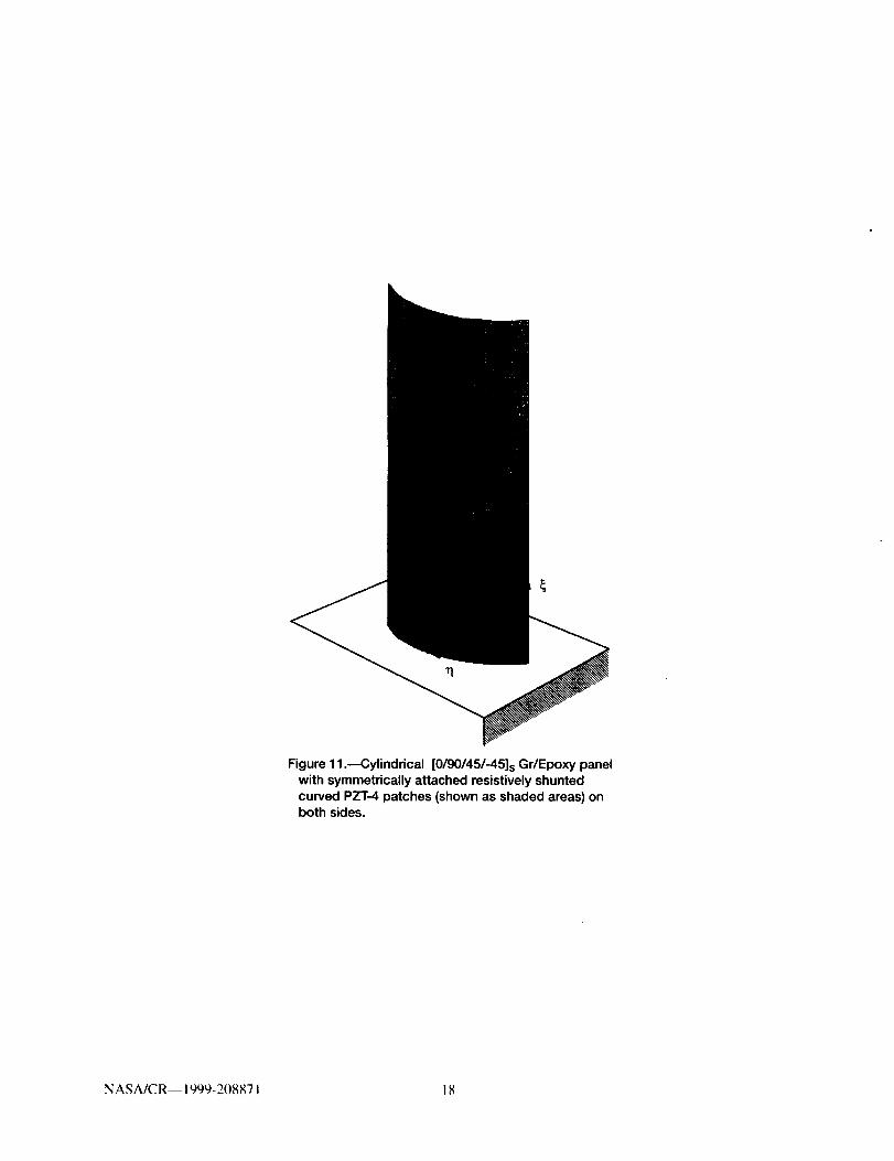
Figure 11 .---Cylindrical [0/90/45/-45]s Gr/Epoxy panel
with symmetrically attached resistively shunted
curved PZT-4 patches (shown as shaded areas) onboth sides.
NASA/CR-- 1999-208871 18

Form ApprovedREPORT DOCUMENTATION PAGE OMB No. 0704-0188
Public reporting burden for this collection of information is estimated to average 1 hour per response, including the time for reviewing instructions, searching existing data sources,
gathering and maintaining the data needed, and completing and reviewing the collection of information, Send comments regarding this burden estimate or any other aspect of this
collection of information, including suggestions for reducing this burden, to Washington Headquarters Services, Directorate for Information Operations and Reports, 1215 Jefferson
Davis Highway, Suite 1204. Arlington, VA 22202-4302, and to the Office of Management and Budgel, Paperwork Reduction Project (0704-018,8), Washington, DC 20503
1. AGENCY USE ONLY (Leave blank) 2. REPORT DATE 3. REPORT TYPE AND DATES COVERED
March 1999 Final Contractor Report
4. TITLE AND SUBTITLE i5. FUNDING NUMBERS
Passively Damped Laminated Piezoelectric Shell Structures
With Integrated Electric Networks
6. AUTHOR(S)
Dimitris A. Saravanos
7. PERFORMING ORGANIZATION NAME(S) AND ADDRESS(ES)
Ohio Aerospace Institute
22800 Cedar Point Road
Cleveland, Ohio 44142
9. SPONSORING/MONITORING AGENCY NAME(S) AND ADDRESS(ES)
National Aeronautics and Space Administration
John H. Glenn Research Center at Lewis Field
Cleveland, Ohio 44135-3191
WU-523-21-13-00
NCC3-455
8. PERFORMING ORGANIZATIONREPORT NUMBER
E-I1515
10. SPONSORING/MONITORING
AGENCY REPORT NUMBER
NASA CR-- 1999-208871
11. SUPPLEMENTARY NOTES
Proiect Manager, Dale Hopkins, Structures and Acoustics Division, organization code 5930, (216) 433-3260.
12a. DISTRIBUTIONIAVAILABILITY STATEMENT
Unclassified - Unlimited
Subject Category: 39 Distribution: Nonstandard
This publication is available from the NASA Center for AeroSpace Information, (301) 621-0390
12b. DISTRIBUTION CODE
13. ABSTRACT (Maximum 200 words)
Multi-field mechanics are presented for curvilinear piezoelectric laminates interfaced with distributed passive electric
components. The equations of motion for laminated piezoelectric shell structures with embedded passive electric
networks are directly formulated and solved using a finite element methodology. The modal damping and frequencies of
the piezoelectric shell arc calculated from the poles of the system. Experimental and numerical results are presented for
the modal damping and frequency of composite beams with a resistively shunted piezoceramic patch. The modal
damping and frequency of plates, cylindrical shells and cylindrical composite blades with piezoelectric-resistor layers
are predicted. Both analytical and experimental studies illustrate a unique dependence of modal damping and frequen-
cies on the shunting resistance and show the effect of structural shape and curvature on piezoelectric damping.
14. SUBJECT TERMS
Damping; Composite structures; Smarl structures; Shells: Piezoelectric ceramics: Finite
element method
17. SECURITY CLASSIFICATIONOF REPORT
Unclassified
NSN 7540-01-280-5500
18. SECURITY CLASSIFICATIONOF THIS PAGE
U nc lassi fled
19. SECURITY CLASSIFICATION
OF ABSTRACT
Unclassified
15. NUMBER OF PAGES
2516. PRICE CODE
A0320. LIMITATION OF ABSTRACT
Standard Form 298 (Rev. 2-89)Prescribed by ANSI Std Z39-18
298-102
0.02
o 0.015
¢ln_
0i
Q.E 0.01tlc_i
m"oO5
0.005
0 ""_'0.1
f
Jl °" %
_f'" t
/ -,t
I
ii
ii
i
/"/"
I
t
-%
mode 1
g
2
e • i
3oeaeDo
4
5
eli m
_bS Q _
1 10 100 1000
Resistance RA (Ohms sq-m)
Figure 12.--Damping predictions for the first 5 modes of the cantilever cylindrical [0/90/45/-45]sGr/Epoxy panel.
NASA/CR-- 1999-208871 19