patente tesla us7382072
TRANSCRIPT
(12) United States Patent
US007382072B2
(10) Patent N0.: US 7,382,072 B2 Erfourth (45) Date of Patent: Jun. 3, 2008
(54) GENERATOR OTHER PUBLICATIONS
(75) Inventor; Eric J, Erfourths Minneapolis, MN Unknown author, Moving Magnet Generator, University of Michi (US) gan Physics Department, 1 page, Mar. 14, 2001.*
(73) Assignee: Erfurt & Company, Minneapolis, MN (Continued) (Us) Primary ExamineriKarl Tamai
- - - - - Assistant ExamineriDavid W. Scheuermann ( * ) Notrce: Subject to any drsclarmer, the term of this _
patent is extended or adjusted under 35 (74) Attorney, Agent, or FtrmiLe?‘ert Jay & PolglaZe, P.A.
U.S.C. 154(b) by 0 days. (57) ABSTRACT
(21) Appl. No.: 10/672,313
(22) Filed; Sep_ 26, 2003 An ef?cient and recon?gurable permanent magnet generator that comprises a permanent magnet subassembly and at least
(65) Prior Publication Data one exciter is disclosed. The permanent magnet generator
Us 200 4 /0232792 A1 NOV‘ 25’ 200 4 may comprise a marnframe comprising at least one excrter, and a permanent magnet subassembly comprrsrng a pluralrty
Related US Application D at a ‘oftmagnetts that are arrtanged1 to ~formhiathlegllst otni: air gap ' ~ ~ ' eWeen acrng magne 1c po es in W 0 e a eas one
(60) PIN/151011211aPPhCaUOIINO-60/472,637,?1ed 011 May exciter resides and that are recon?gurable for alternating 22, 2003- current or direct current operation by inversion of respective
magnetic poles. The at least one exciter may comprise a (51) Int- Cl- plurality of alternating layers of a ?rst material and a second
H02K 21/12 (2006-01) material, Where the ?rst material may comprise a supercon 6 ductive material and the second material may comprise a
52 U 5 Cl ( ' 3 1)0/15 6 09_ 310/156 32 non-superconductive material, and Wherein the layers of the ( ) ‘ ‘ ‘ 43_ 31'0/1’58_ 310/1'78f superconductive material are thin relative to the thickness of
' ’ ' ’ / ’_ / ’ the layers of the non-superconductive material. A method for _ _ _ 505 166’ 505 876 generating electric energy using a recon?gurable permanent
(58) Field of Classi?cation Search ......... .. 310/156.01, magnet generator is also disclosed The method Comprises 310/15608, 156-09, 15632, 15638, 15639, selecting an alternating current or a direct current generation
310/156-43, 156-45, 158, 156-339, 178; 505/166, mode; con?guring at least one recon?gurable magnet to ~ ~ . 505/876 correspond With the selected generation mode; disposing at
See applrcatron ?le for complete search hrstory. least one excrter 1n an arr gap de?ned by the at least one
56 R f Ct d recon?gurable magnet; and ( ) e erences l e rotating the at least one recon?gurable magnet relative to the
US, PATENT DOCUMENTS at least one exciter. The disclosed generator may thus
428,057 A 5/1890 Tesla produce‘ either alternating current (AC) or direct current C _ d (DC) usrng alternative con?guratrons of the same mecham
( Onnnue ) cal components. FOREIGN PATENT DOCUMENTS
EP 429729 Al * 6/1991 39 Claims, 17 Drawing Sheets
mo 10‘!
\ m7 /,,, A ,m. 11”‘
r lib
10b
M4 m1
US 7,382,072 B2 Page 2
US. PATENT DOCUMENTS 5,892,311 A 4/1999 Hayasaka 5,917,261 A 6/1999 Kawai
433,702 A 8/1890 Tesla 5,925,958 A 7/1999 Piere 447,921 A 3/1891 Tesla 5,955,809 A 9/1999 Shah 511,916 A V1894 Tesla 6,002,193 A 12/1999 Caninietal.
1,061,206 A 5/1913 Tesla 6,037,696 A 3/2000 Sromin 6161. 2,806,159 A 9/1957 Sheldon 6,097,118 A 8/2000 Hull 3,493,800 A 2/1970 Barrett 6,100,620 A 8/2000 Radovsky 3,538,364 A 11/1970 Favereau 6,127,764 A 10/2000 Torok 4,827,171 A 5/1989 Bertram eta1~ 6,147,415 A 11/2000 Fukada 5,117,142 A 5/1992 VOn Zweygbergk 6,169,352 B1 1/2001 Hull 5,227,702 A 7/1993 Nahirney .................. .. 318/138 6,172,438 B1 1/2001 Sakamoto 5,325,002 A 6/ 1994 R?blnowltz et 31 6,462,449 B1 10/2002 Lucidarme et al. 5,350,958 A 9/1994 Ohnishi 5,554,903 A 9/1996 Takara OTHER PUBLICATIONS
5’608’28l A 3/1997 Ger.llng et a1‘ “Superconducting YBa2CU3O7_X Films on Copper Substrates”, 5,625,241 A 4/1997 Ewing et al. - - - - Anqu1 Wu, Richard T. Williams, C. Thomas Law, G.E. Matthews, 5,650,680 A 7/1997 Chula . . Jr.; Howard W. Shields; T1lman Prater; Robert D. Eyster; George B. 5’696’4l9 A 12/1997 Rakestraw et 31' Cvijanovich' AMP Journal of Technology vol. 1 Nov. 1991. 5,719,458 A 2/1998 Kawai ’ ’ ’
5,841,211 A 11/1998 Boyes * cited by examiner
U.S. Patent Jun. 3, 2008 Sheet 1 0f 17 US 7,382,072 B2
B
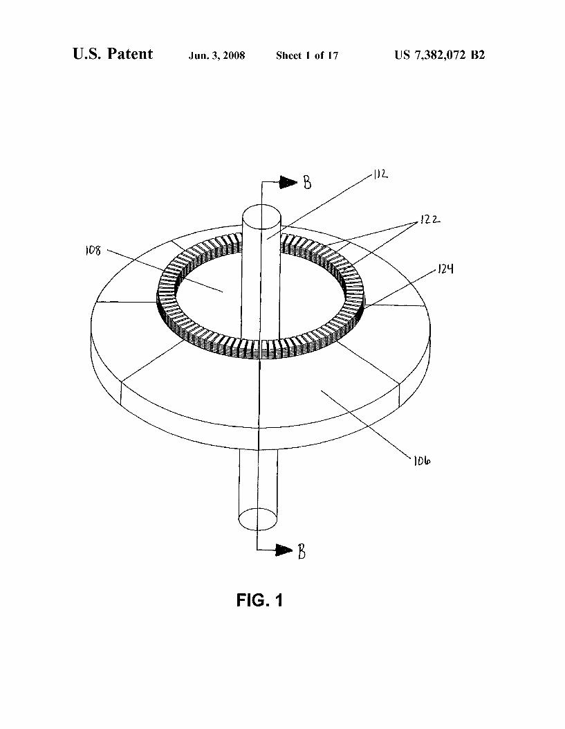
FIG. 1
U.S. Patent Jun. 3, 2008 Sheet 2 0f 17 US 7,382,072 B2
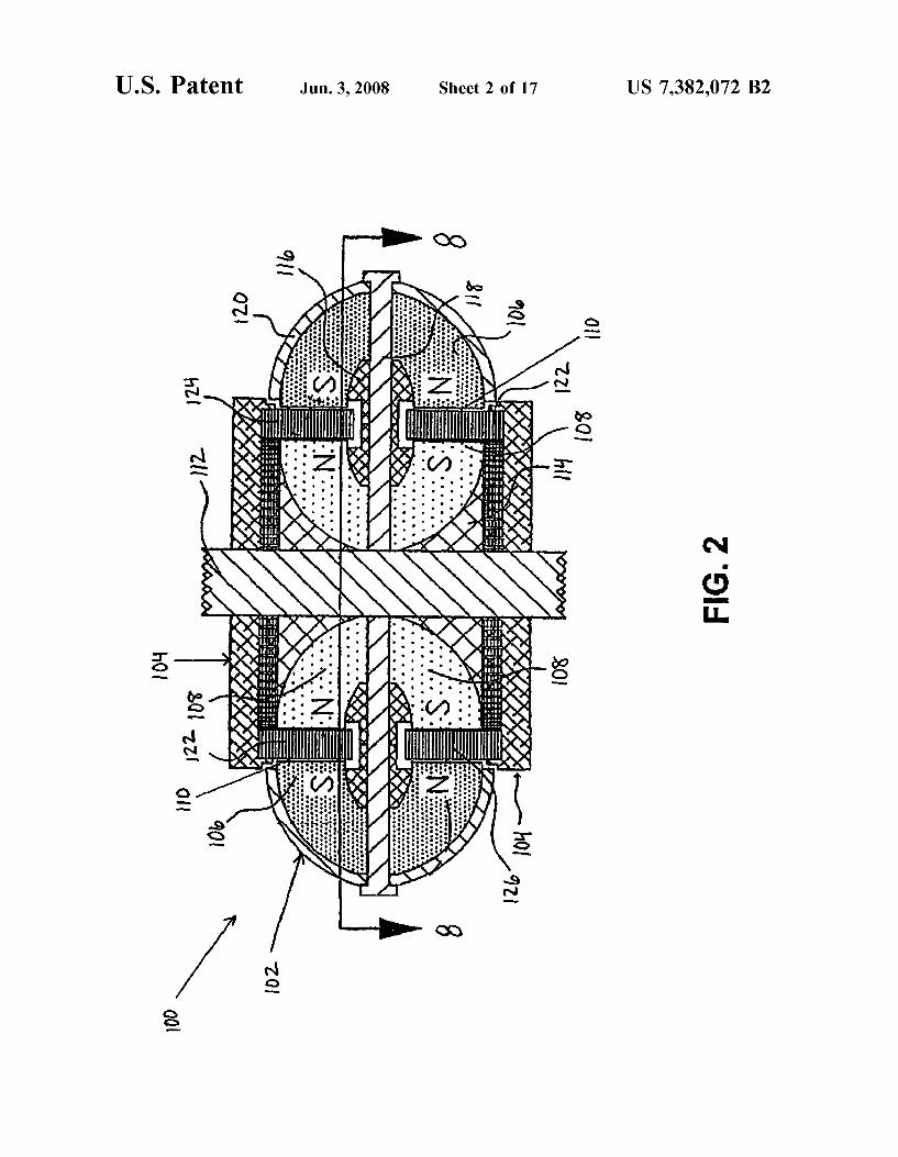
N .0E
2 *2
as J: m9
"Hill"!!!
0- I. 0-- 0;
. . . . . . . . u 4 . 1....
. . . . . . . . II 9 ...-........................ . . . . . . . vQHQH0>¢§<>Q>QHQV llllll IIIHIII
mink‘:
U S. Patent Jun. 3, 2008 Sheet 3 0f 17 US 7,382,072 B2
122.
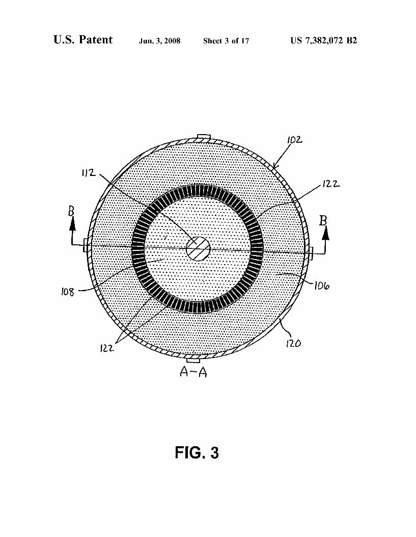
FIG. 3
U.S. Patent Jun. 3, 2008 Sheet 4 0f 17 US 7,382,072 B2
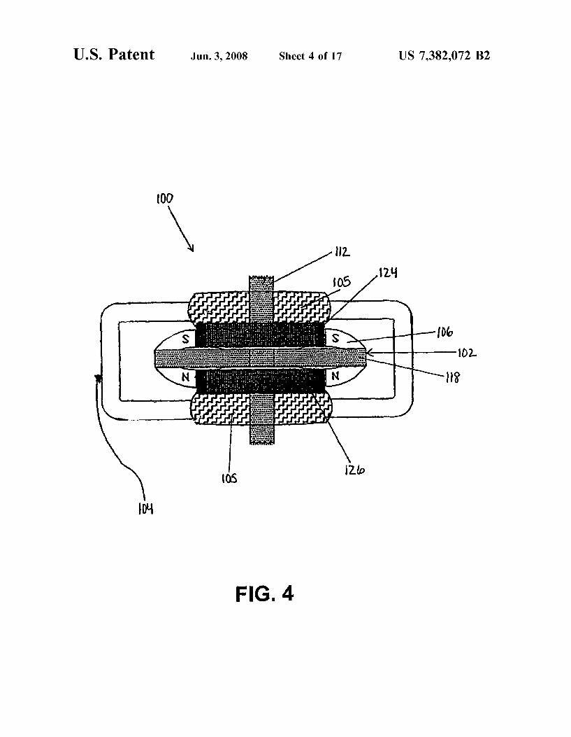
I00
I00 102.
H?
1210
NH
FIG. 4
U.S. Patent Jun. 3, 2008 Sheet 5 0f 17 US 7,382,072 B2
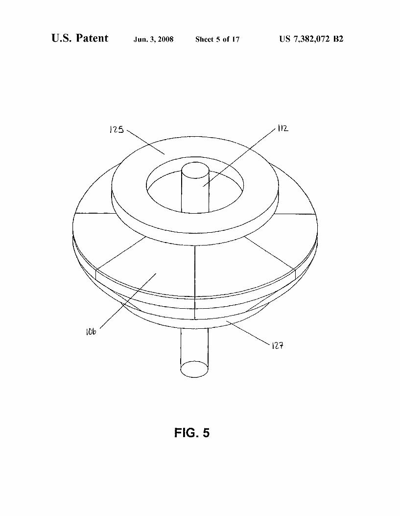
FIG. 5
U.S. Patent Jun. 3, 2008 Sheet 7 0f 17
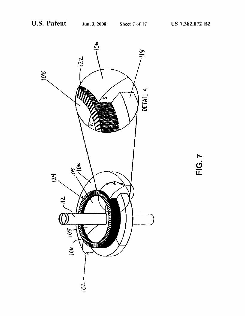
10b 11%’
I015’
DETAIL A
U/V / s \\
my I I
I
$ 2
I02.
US 7,382,072 B2
FIG. 7
U.S. Patent Jun. 3, 2008 Sheet 8 0f 17 US 7,382,072 B2
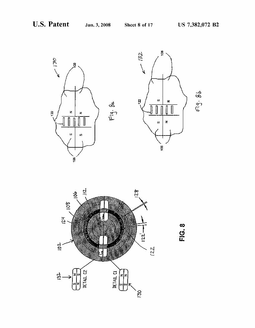
1
FIG. 8
U.S. Patent Jun. 3, 2008 Sheet 9 0f 17 US 7,382,072 B2
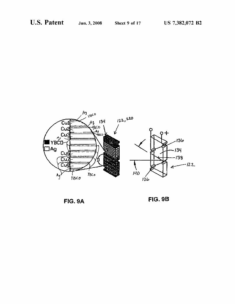
FIG. 98 FIG. 9A
U.S. Patent Jun. 3, 2008 Sheet 10 0f 17 US 7,382,072 B2
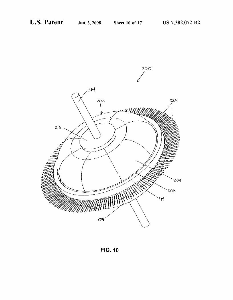
ZOO
ZZPI
// / 1
W22
\/
FIG. 10
U.S. Patent Jun. 3, 2008 Sheet 11 0f 17 US 7,382,072 B2
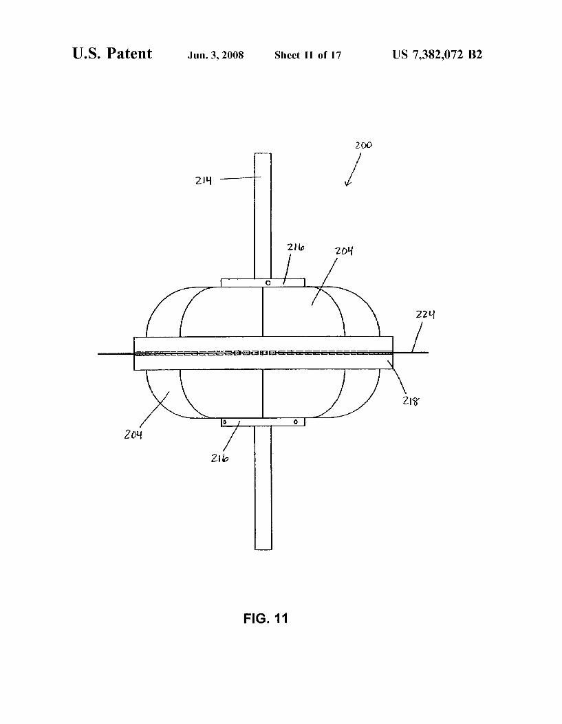
200
21% I‘“ /
ff *0 f __%_gmgaaa
FIG. 11
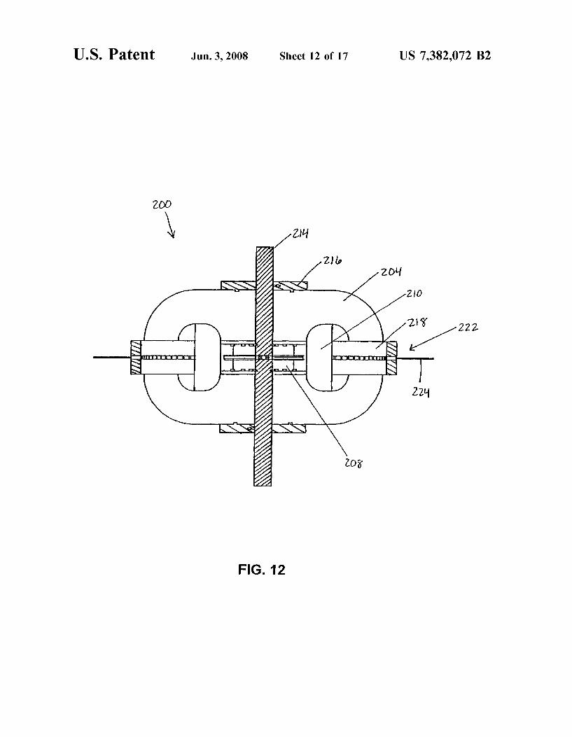
U.S. Patent Jun. 3, 2008 Sheet 12 0f 17 US 7,382,072 B2
222
FIG. 12
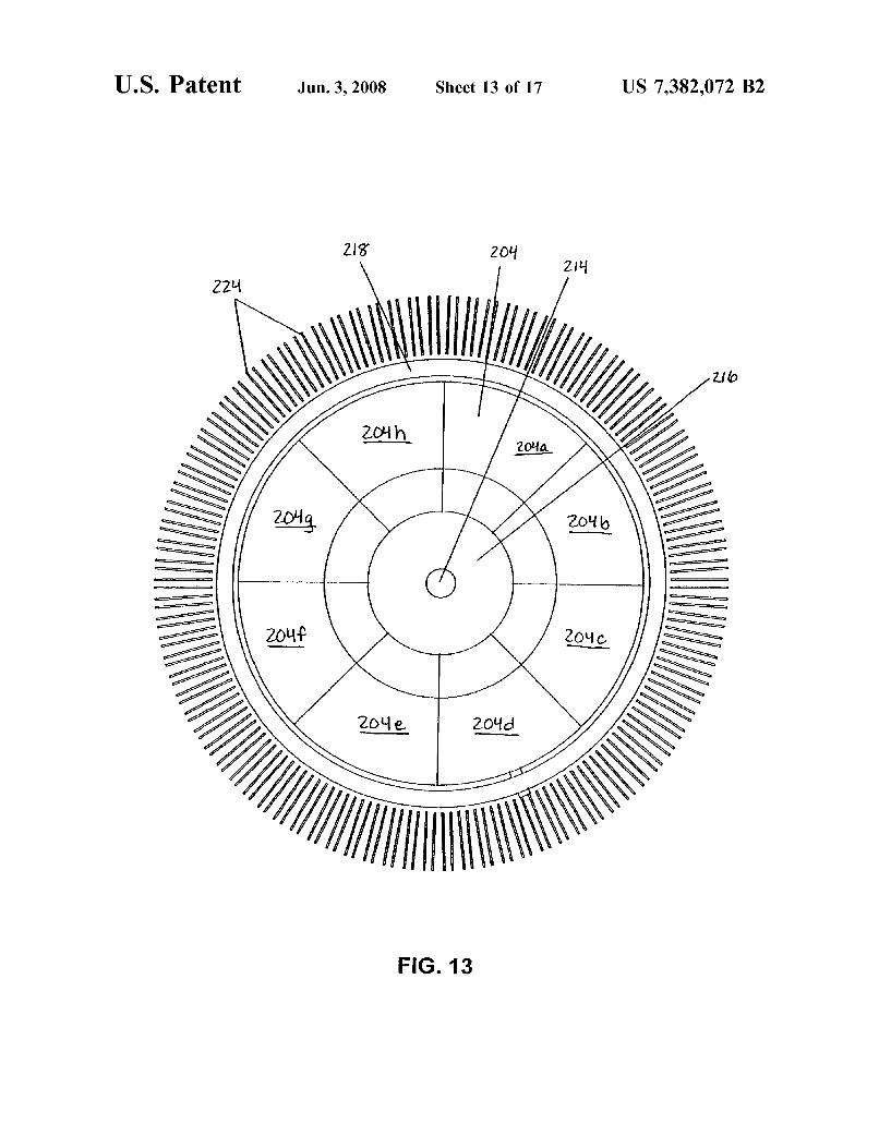
U.S. Patent Jun. 3, 2008 Sheet 13 0f 17 US 7,382,072 B2
FIG. 13
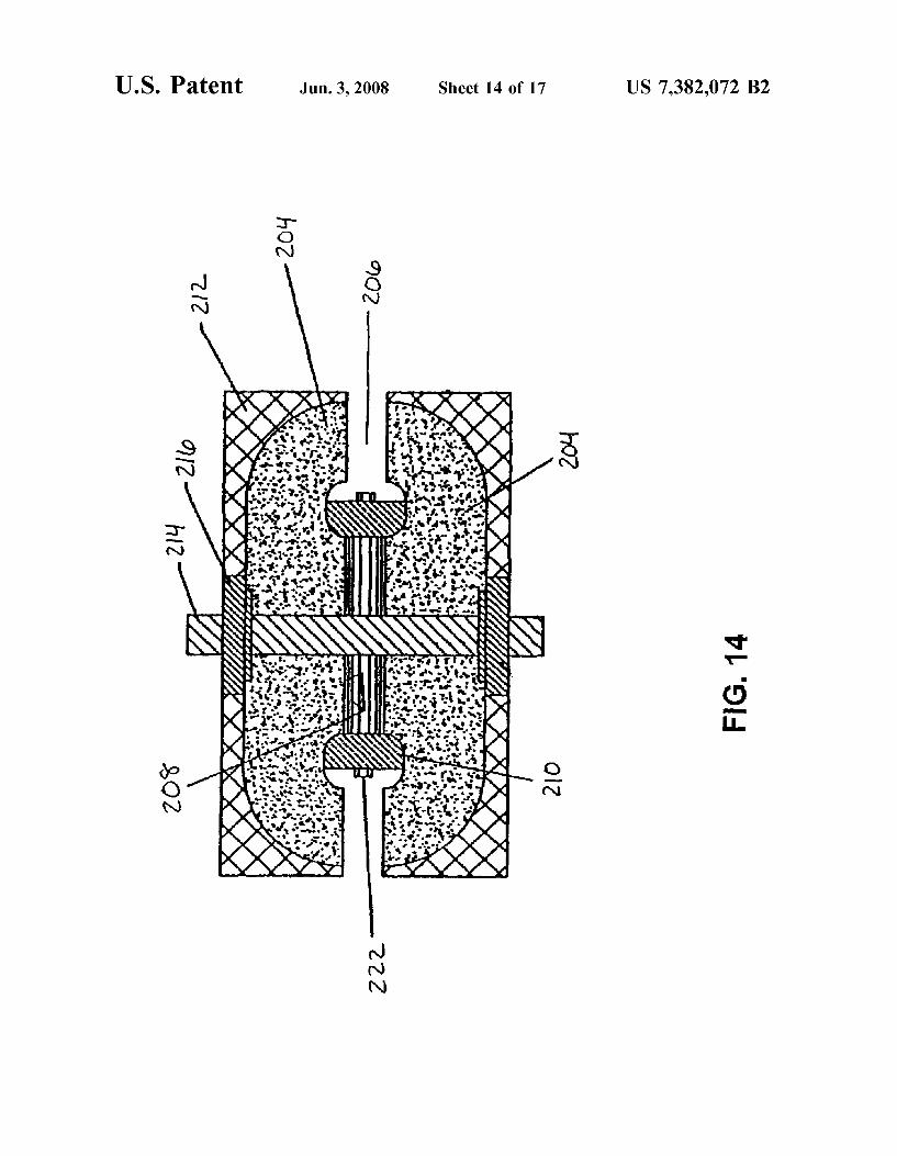
U.S. Patent Jun. 3, 2008 Sheet 14 0f 17 US 7,382,072 B2
2‘ .GE
u on r o ...: v1. 4 ?wwfme i
MNN
SON
l o o I ‘ 2.... w...’ .u... ..\.... v .. nV“."u._.... LKCJFR.
AWN
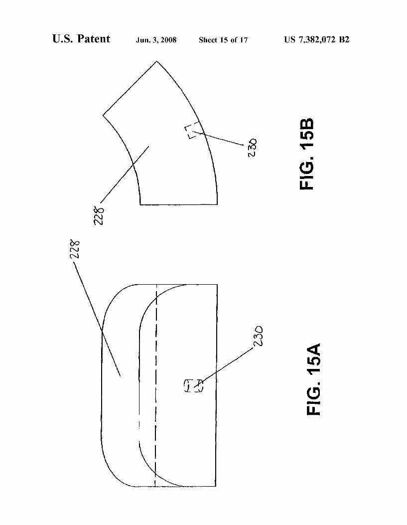
U.S. Patent Jun. 3, 2008 Sheet 15 0f 17 US 7,382,072 B2
mm? .OE 0mm
\wNN
4m? .OE /
0mm
K Fl
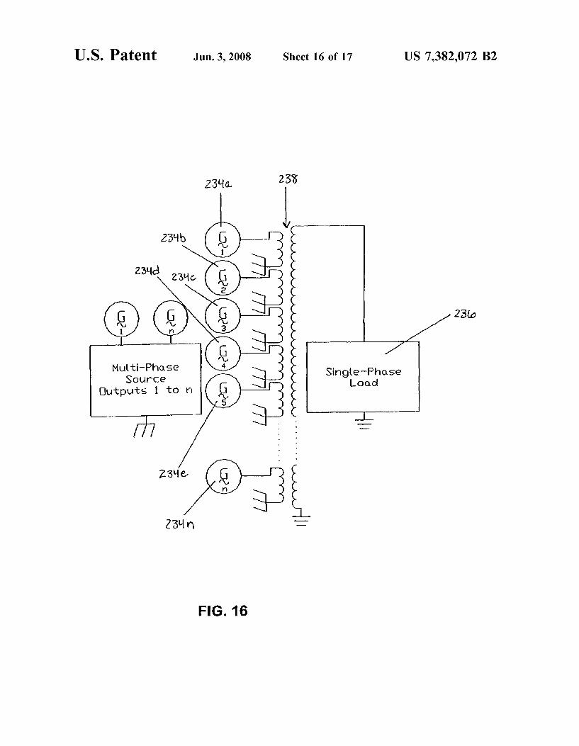
U.S. Patent Jun. 3, 2008 Sheet 16 0f 17 US 7,382,072 B2
23%» 23%
23%
22016 23% 4
\_
Q - t /
Mulstozilggse Single~Phase Outputs 1 to n \J Load
#7 ' ' "J:
Z3lle g 23% n
/ 23w
FIG. 16
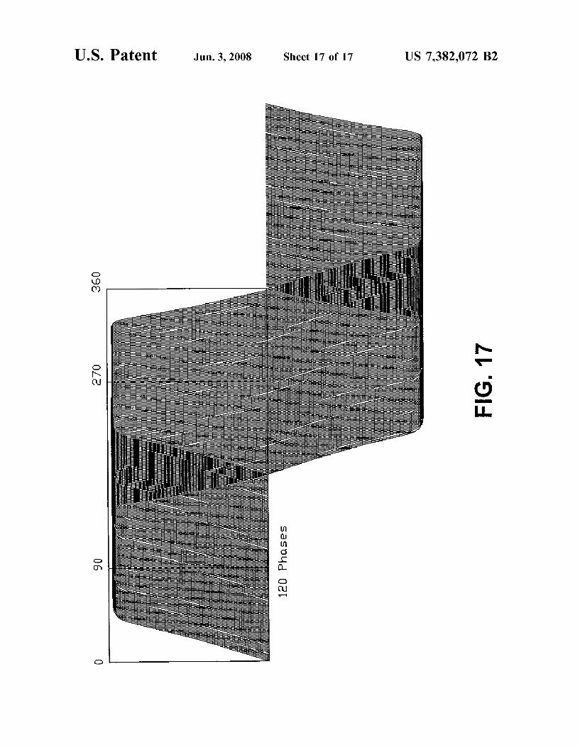
U.S. Patent Jun. 3, 2008 Sheet 17 0f 17 US 7,382,072 B2
5. 40-“
309E 02
0mm ohm cm 0
US 7,382,072 B2 1
GENERATOR
RELATED APPLICATION
The present application claims the bene?t of Us. Provi sional Application No. 60/472,637 ?led May 22, 2003, Which is incorporated herein in its entirety by reference.
FIELD OF THE INVENTION
The present invention relates generally to motors and generators and more particularly to a permanent magnet alternating current and direct current electric poWer genera tor and method for generating alternating current and direct current electric poWer.
BACKGROUND OF THE INVENTION
In simple terms, a generator is a device for converting mechanical energy into electrical energy and Works by electromagnetic induction. A poWer source drives a coil Winding, causing it to rotate betWeen the poles of a perma nent magnet or electromagnet. As the coil Winding spins and cuts through the lines of force betWeen the poles of the magnet, potential energy and electric current is generated and ?oWs through the coil Winding. The electric current that is generated may be either direct current (DC) or alternating current (AC). In AC generation, a sinusoidal output Wave form is produced; no energy is induced as the coil Winding rotates parallel to the magnetic ?ux lines, While maximum poWer is achieved When the coil Winding is rotating tangen tial to the magnetic ?ux lines.
The ?rst electric generators, or dynamos, Were modeled and built in the 1830s. By the end of the nineteenth century, signi?cant advances Were being made in the ?eld of elec trical generation, particularly by Nikola Tesla. In 1890, Tesla disclosed a pyromagneto-electric generator in Us. Pat. No. 428,057, in Which he recogniZed that the magnetic proper ties of iron and other magnetic substances may be compro mised by raising the material to a certain temperature and restored by again loWering the temperature. Also in 1890, Tesla disclosed an electrical transformer or induction device in Us. Pat. No. 433,702.
Alternating current generators in use at the time typically provided from one to three hundred alterations of current per second. It Was soon recogniZed that higher rates of alteration Would be an advantage. Producing higher rates of alteration With generator designs at the time, hoWever, Was di?icult and resulted in decreased e?iciency, primarily due to high magnetic leakage, and improved generator designs Were sought. In Us. Pat. No. 447,921, Tesla discloses a ?eld magnet core made up of tWo independent parts formed With grooves for the reception of one or more energiZing coils. The energiZing coils are completely surrounded by the iron core, except on one side, Where there is a narroW opening betWeen the polar faces of the core, and the polar faces of the core are formed With many projections or serrations. This ?eld-magnet design produced less magnetic leakage but still did not operate at a desired level of e?iciency.
In 1894, Tesla disclosed an electric generator in Us. Pat. No. 511,916. This generator Was capable of continued production of electric currents of constant period by impart ing the movements of a piston to a core or coil in a magnetic ?eld. By the tWentieth century, more reliable turbines Were in
use, capable of providing 50-60 Hertz poWer With 3000 3600 alternations of current per second. In Us. Pat. No.
20
25
30
35
40
50
55
60
65
2 1,061,206, Tesla discloses a turbine that improves the use of ?uids as motive agents by causing a propelling ?uid to move in natural paths or stream lines of least resistance, avoiding losses due to sudden variations While the ?uid is imparting energy. This method, When coupled With poWer generating equipment, provided a more e?icient and reliable means of hydraulic poWer synthesis.
Another conventional generator example is the Detroit Edison generator. The Detroit Edison generator includes an outer extruded stationary permanent magnet With opposite magnetic poles forming an air gap at the center, With a number of Windings rotated Within the air gap to induce current in the rotating Windings. As With other early gen erator designs, increased and improved e?iciency Was sought, often realiZed by increasing the length of the cylin drical generator.
Generator designs continued to advance in the tWentieth century, Where improvements made to the above-identi?ed generator designs frequently focused on improving e?i ciency. U.S. Pat. No. 3,538,364, to Favereau, discloses a rotary electric machine comprising a ?xed primary stator in the form of a pair of concentrically arranged inner and outer stator elements having magnetic poles and betWeen Which, in an air gap, the secondary cylindrical rotor having a Winding thereon is mounted for rotation. The magnetic stator provides a 360-degree air gap betWeen opposite magnetic poles in the inner and outer stator. This arrangement reduced the siZe of leakage ?uxes and reduced the volume of the coils situated around the poles, permitting increases in the Working induction in the cylindrical air gap. More recently, improvements have recogniZed and
addressed optimizing the Waveshape of the generator output to maximiZe generator output and improve e?iciency. In Us. Pat. No. 5,650,680, Chula discloses a permanent mag net generator having a rotor including a plurality of perma nent magnets generating an operative magnetic ?ux ?eld, seeking to create an output voltage signal With reduced harmonic content.
Conventional generator designs typically include con tacts, or “brushes,” that rotate relative to electrical contacts and provide a circuit for electricity to ?oW through. Brushes, hoWever, require regular maintenance and replacement as they become Worn. Additionally, the electrical resistance of the brushes and the mechanical frictional loss betWeen the brushes and the contacts decrease generator e?iciency. These draWbacks Were recogniZed by RakestraW et al. in Us. Pat. No. 5,696,419, Which discloses an electrical gen erator With a plurality of C-shaped stator members made of magnetically permeable material. A ?at ring-shaped rotor de?nes a periphery, and a plurality of permanent magnets are positioned around the periphery. The rotor is positioned With the magnets of the rotor disposed in the gap de?ned by the stator members, so that When the rotor is rotated by a prime mover to move the magnets through the gap, an electrical current is induced in the stator Windings.
Others have sought to improve generator e?iciency by not only eliminating brushes but also improving per-magnet rotor excitation. In Us. Pat. No. 6,462,449, Lucidarme et al. disclose a rotating electric machine Where the rotor includes a magnetic ?eld core provided With radial teeth, uniformly distributed at its periphery. Annular magnets are arranged on either side of the core axial ends and magnetic end ?anges pressing the annular magnets against the core. Magnetic bars link the end betWeen each of the bars and at least the side Walls of the core radial teeth de?ning the spaces. The stator includes a magnetic core, excitation coils arranged on either side of the core, a stator coil Wound on the core, and a