pavement design guidelines, pdg1: pavement design ...research4cap.org/library/mtrd_2017... ·...
TRANSCRIPT


F1

F2

F3

PDG-1 Low Volume Sealed Roads
Table of Contents
i
�������������� ��
Chapter 1:� Introduction 1�
1.1� Design Process 1�
1.2� Design Traffic Classes 3�
1.3� Subgrade and Foundation Classes 3�
1.4� Typical Pavement Structures for LVSR 4�
Chapter 2:� Traffic 5�
2.1� Introduction 5�
2.2� Vehicle Classification 5�
2.3� Traffic Surveys 6�
2.3.1� Introduction 6�
2.3.2� Traffic Volume Surveys 6�
2.3.3� Origin-Destination Surveys 9�
2.3.4� Axle Load Surveys 10�
2.4� Determination of Design Traffic 11�
Step 1 - Select Design Period 11�
Step 2 - Estimate Initial Traffic Volume per Vehicle Class 11�
Step 3 - Traffic Growth Rate per Vehicle Class 12�
Step 4 - Mean ESA per Vehicle Class 12�
Step 5 - Mean Daily ESA for all Vehicle Classes 13�
Step 6 - Adjustment of the Computed DESA 13�
Step 7 - Cumulative ESA (CESA) for all Vehicle Classes over the Design Period 13�
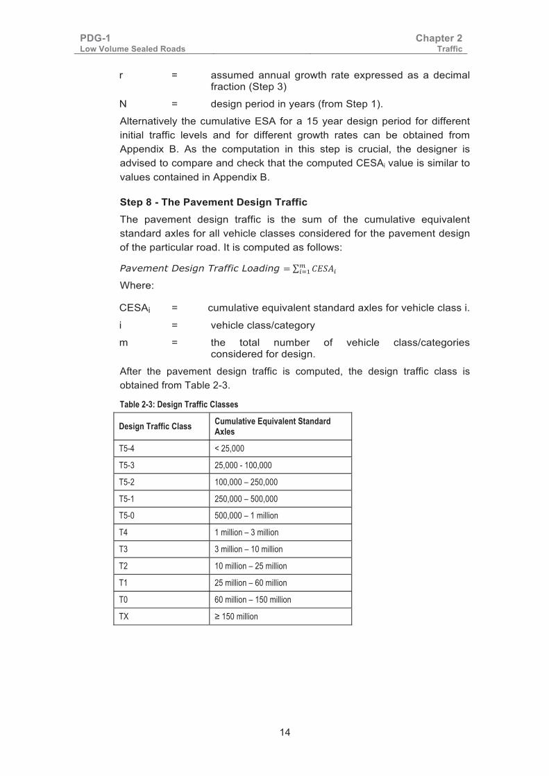
Step 8 - The Pavement Design Traffic 14�
Chapter 3:� Subgrade Classification 15�
3.1� Introduction 15�
3.2� Subgrade Sampling 15�
3.3� Determining Subgrade Bearing Strength Class 16�
3.4� Classification of the Most Common Kenyan Soils 19�
3.5� Rapid Determination of Homogenous Subgrade Sections 19�
Chapter 4:� Pavement Foundation 23�
4.1� Introduction 23�
4.2� Suitable Subgrade Materials for Pavement Support 23�
4.3� Unsuitable Materials 24�
4.3.1� Rock Outcrops 24�
PDG-1 Low Volume Sealed Roads
Table of Contents
ii
4.3.2� Swampy Areas 24�
4.3.3� Expansive Clays 25�
4.3.4� Dispersive Soils 27�
4.3.5� Collapsible Soils 28�
4.4� Design of Improved Subgrade 28�
Chapter 5:� Pavement Materials 31�
5.1� Introduction 31�
5.2� Classification of Materials 31�
5.3� Natural Materials 33�
5.4� Graded Crushed Stone 34�
5.5� Hydraulically Improved Granular Materials 35�
5.6� Bitumen Stabilised Materials 36�
5.7� Hand-Packed Stone 39�
5.8� Interlocking Cobblestone Paving 40�
5.9� Interlocking Concrete Block Paving 41�
5.10� Cement Concrete Pavements 43�
5.11� Surface Treatment 43�
5.11.1� Prime Coat 43�
5.11.2� Tack Coat 44�
5.12� Surfacing 45�
5.12.1� Surface Dressing 45�
5.12.2� Cold Mix Asphalt 46�
5.12.3� Slurry Seal and Cape Seal 47�
5.12.4� Otta Seal 47�
5.12.5� Sand Seal 48�
5.12.6� Combination Seals 48�
5.12.7� Road Oiling 48�
5.13� Materials Specification Charts 50�
Chapter 6:� Pavement Design Principles and Methods 74�
6.1� Introduction 74�
6.2� Design Criteria 74�
6.3� Subgrade Characterisation 75�
6.3.1� Subgrade Failure Criterion 75�
6.3.2� Subgrade Stiffness Modulus 76�
6.3.3� Pavement Foundation Classes 77�
6.4� The Structural Number Method 77�

PDG-1 Low Volume Sealed Roads
Table of Contents
iii
6.5� Characterisation of Granular Materials 78�
6.6� Characterisation of Hydraulically or Bitumen Modified Materials 78�
6.7� Calculation of Stress, Strain and Layer Thickness 79�
6.7.1� Calculation of Stress and Strain 79�
6.7.2� Determination of Layer Thicknesses 80�
Chapter 7:� Pavement Cross Sections and Drainage 81�
7.1� Shoulders 81�
7.1.1� Functions and Purposes of Shoulders 81�
7.1.2� Different Types of Shoulders and Materials 81�
7.1.3� Shoulder Material Requirements 82�
7.1.4� Protection of Shoulder Surfacing 82�
7.1.5� Kerbs 82�
7.2� Pavement Drainage 82�
7.2.1� Drainage of Road Surface and Shoulders 82�
7.2.2� Internal Drainage of Pavement Layers 83�
7.3� Pavement Cross-sections 83�
7.3.1� Carriageway Dimensions 83�
7.3.2� Shoulder Widths 83�
7.3.3� Edge Restraint 84�
7.3.4� Shoulder Slopes in Areas of Expansive Clay Subgrades 84�
Chapter 8:� Design Catalogue 85�
8.1� Introduction 85�
8.2� The Standard Pavement Structures 85�
8.3� The Use of Other Types of Pavement 85�
8.4� Method of Use 86�
8.4.1� Pavement Structure Type LV1 (G30 Base) 86�
8.4.2� Pavement Structure Type LV2 (G50 Base/G25 Sub-base) 88�
8.4.3� Pavement Structure Type LV3 (G80 Base/G30 Sub-base) 90�
8.4.4� Pavement Structure Type LV4 (HIG60 Base) 92�
8.4.5� Pavement Structure Type LV5 (HIG100 Base/G25 Sub-base) 94�
8.4.6� Pavement Structure Type LV6 (HIG160 Base/G30 Sub-base) 96�
8.4.7� Pavement Structure Type LV7 (HIG100 Base/HIG50 Sub-base) 98�
PDG-1 Low Volume Sealed Roads
Table of Contents
iv
8.4.8� Pavement Structure Type LV8 (HIG160 Base/HIG60 Sub-base) 100�
8.4.9� Pavement Structure Type LV9 (BESM 3 Base/G25 Sub-base) 102�
8.4.10� Pavement Structure Type LV10 (BESM 3 Base/G30 Sub-base) 104�
8.4.11� Pavement Structure Type LV11 (HPS Base/G30 Sub-base) 106�
8.4.12� Pavement Structure Type LV12 (Interlocking Cobblestone Surfacing on G30 Base) 108�
8.4.13� Pavement Structure Type LV13 (Interlocking Concrete Block Surfacing on G30 Base) 110�
8.4.14� Pavement Structure Type LV14 (Cement Concrete Base or Surfacing on G30 Sub-base) 112�
�
Appendices
A Estimation of Diverted and Generated Traffic
B Reference Table for Computation of CESA
C Classification of Alignment Soils
D Calculated Subgrade Strains for LV1, LV2, and LV3 Designs
E The Structural Number Approach to Design of Road Pavements
�
�
�
�

PDG-1 Low Volume Sealed Roads
Table of Contents
v
�� ���������� �Figure 2-1: Traffic Count Adjustment in Relation to Seasonal Characteristics ................................................................................................. 9�
Figure 2-2: A 5-axle Articulated Truck (2:4:4+4:4) ......................................... 12�
Figure 3-1: Determining the Subgrade Bearing Strength Class .................... 18�
Figure 6-1: Permissible Vertical Strain on the Subgrade .............................. 76�
������������ ���������� �
Figure A-1: Schematic of a Network Layout
Figure A-2: Traffic Tallying Form
Figure C-1: Plasticity Chart for the Classification of Fine Soils and the Finer Part of Coarse Soils (<425µm)
Figure C-2: Fuller Description of Gravels and Sands
Figure C-3: The grading Triangle for Soil Classification (material finer than 60mm)
Figure C-4: Mixtures of Very Coarse Materials (Boulders and Cobbles) and Finer Material
Figure D-1: Strains, S1
Figure D-2: Strains, S2
Figure D-3: Strains, S3
Figure D-4: Strains, S4
Figure D-5: Strains, S5
Figure E-1: Structural Number versus Traffic, for Various Subgrade Strengths
Figure E-2: Structural Number versus Subgrade CBR, for Various Traffic Levels
�
�
�
�
� �

PDG-1 Low Volume Sealed Roads
Table of Contents
vi
�
�� ��������� �Table 1-1: Design Traffic Classes ................................................................... 3�
Table 1-2: Subgrade Classes .......................................................................... 3�
Table 1-3: Pavement Foundation Classes and Stiffness Modulus .................. 3�
Table 1-4: Typical Pavement Structures for LVSR .......................................... 4�
Table 1-5: Surfacing Options for LVSR ........................................................... 4�
Table 2-1: Vehicle Classification System ........................................................ 5�
Table 2-2: Lane Width Adjustment Factors for Design Traffic Loading ......... 13�
Table 2-3: Design Traffic Classes ................................................................. 14�
Table 3-1: Minimum Number of Samples and Sampling Interval .................. 15�
Table 3-2: Subgrade CBR Bearing Strength Classes ................................... 16�
Table 3-3: Classification of Kenyan Subgrade Soils ...................................... 19�
Table 5-1: Specifications for Capping and Pavement Materials .................... 31�
Table 5-2: Cobblestone Dimensions ............................................................. 41�
Table 5-3: Grading Criteria and Application of Paving Blocks ....................... 42�
Table 5-4: Categories by Dimensions of Paving Blocks ................................ 42�
Table 6-1: Subgrade Surface Moduli ............................................................. 76�
Table 6-2: Pavement Foundation Classes .................................................... 77�
Table 6-3: Characteristic Modulus for Granular Materials ............................. 78�
Table 6-4: Characteristic Modulus for Hydraulically Modified Granular Materials ........................................................................................................ 79�
Table 6-5: Characteristic Modulus for Bitumen Modified Granular Materials ........................................................................................................ 79�
Table 8-1: Guide to Pavement Type Selection .............................................. 85�
����������� ��������� �Table A-1: Recording and summation of normal and diverted traffic
Table B-1: Lookup Table for CESA
Table C-1: Alignment Soil Test Results Form
Table C-2: Particle Size Ranges and Nomenclature of Soil Groups
Table C-3: Soil Groups according to British Soil Classification System for Engineering Purposes
Table E-1: Pavement Layer Strength Coefficients
Table E-2: Adjusted Structural Number Model Coefficients

PDG-1 Low Volume Sealed Roads
Table of Contents
vii
�

PDG-1 Low Volume Sealed Roads
Acronyms and Abbreviations
viii
�� ����������� ����������������� � Acronyms
AADT - Annual Average Daily Traffic
AASHO - American Association of State Highway Officials
AASHTO - American Association of State Highway and Transportation Officials
AC - Asphaltic Concrete
ACV - Aggregate Crushing Value
ADT - Average Daily Traffic
B - Bus
BESM - Bitumen Emulsion Stabilised Materials
BISAR - Bitumen Stress Analysis in Roads
C - Car
CBR - California Bearing Ratio
CESA - Cumulative Equivalent Standard Axles
CIM - Cement/lime Improved Material
CP - Concrete Pavement
CPB - Concrete Paving Block
CR - Crushing Ratio
CSIR - Council for Scientific and Industrial Research
CUSUM - Cumulatively Summed
DCP - Dynamic Cone Penetrometer
DESA - Daily Equivalent Standard Axles
DR - Dump Rock
DSD - Double Surface Dressing
EF - Equivalency Factor
EML - Equilibrium Moisture Levels
ESA - Equivalent Standard Axles
ESM - Emulsion Stabilised Materials
ESP - Exchangeable Sodium Percentage
ETB - Emulsion Treated Base
FACT - Fines Aggregate Crushing Test
FI - Flakiness Index
GCS - Graded Crushed Stone
GDP - Gross Domestic Product
GM - Grading Modulus

PDG-1 Low Volume Sealed Roads
Acronyms and Abbreviations
ix
GPS - Global Positioning System
H - Heavy Duty
HGV - Heavy Goods Vehicle
HIG - Hydraulically Improved Gravel
HPS - Hand Packed Stone
HRB - Hydraulic Road Binders
ICC - Initial Consumption of Cement
ICL - Initial Consumption of Lime
ICS - Interlocking Cobble Stone
ITS - Indirect Tensile Strength
KS - Kenyan Standard
L - Light Duty
LAA - Los Angeles Abrasion
LGV - Light Goods Vehicle
LV - Low Volume
LVR - Low Volume Roads
LVSR - Low Volume Sealed Roads
M - Medium Duty
MB - Minibus
MC - Medium Curing
Mc - Motorcycle
MDD - Maximum Dry Density
MGV - Medium Goods Vehicle
MLE - Multi-Layer Elastic
MoT&I - Ministry of Transport and Infrastructure
MTRD - Materials Testing and Research Division
NPRA - Norwegian Public Roads Administration
OB - Omnibus
O-D - Origin – Destination
OMC - Optimum Moisture Content
PC - Pedal Cycle
PI - Plasticity Index
RDM - Road Design Manual
SABITA - Southern African Bitumen Association
SADC - Southern African Development Community
SF - Seasonal Factors
PDG-1 Low Volume Sealed Roads
Acronyms and Abbreviations
x
SN - Structural Number
SNA - Surfacing and base layers contribution to Structural Number
SNC - Modified Structural Number
SNG - Subgrade contribution to Structural Number
SNP - Adjusted Structural Number
SNS - Sub-base and fill contribution to Structural Number
SSD - Single Surface Dressing
SSS - Sodium Sulphate Soundness
TRL - Transport Research Laboratory
UCS - Unconfined Compressive Strength
USA - United States of America
VEF - Vehicle Equivalence Factor
VH - Vibrating Hammer
VPD - Vehicles Per Day
WBM - Water Bound Macadam
Abbreviations cc - Cubic Centimetres
h - Hour
kg - Kilogram
km - Kilometres
kN - Kilo Newton
kPa - Kilo Pascals
l - Litre
m - Metres
m2 - Metre squared
m3 - Metre cubed
mm - Millimetres
mm2 - Millimetre squared
MN - Mega Newtons
MPa - Mega Pascals
N - Newton
Pen - Penetration
µm - Micrometre
� - Mean

PDG-1 Low Volume Sealed Roads
Acronyms and Abbreviations
xi

PDG-1 Low Volume Sealed Roads
Chapter 1 Introduction
1
Chapter 1: Introduction
1.1 Design Process This guideline is intended for the pavement design of low volume roads. For pavement design purposes, low volume roads are considered to have a design traffic loading of less than 1 million equivalent standard axles. Roads with design traffic in excess of 1 million equivalent standard axles should be designed in accordance with the Road Design Manual Part III on Materials and Pavement Design (RDM III).
This guideline is based on RDM III and must be used in conjunction with the Standard specifications for Road and Bridge Construction and other parts of the Road design Manual, especially the Road Design Manual Part I on geometric design and the Roads 2000 Manual.
The pavement terminology is illustrated in Figure 1.1 below.
Figure 1.1 Pavement terminology
The term ‘capping’ is equivalent to the term ‘improved subgrade’ in the RDM III. The capping is used to improve the native subgrade to achieve a new subgrade class or selected design subgrade/foundation class, i.e. construction of the capping results in an improved subgrade.
The pavement foundation is the upper 300mm of the subgrade below formation. Where a capping layer is placed to improve the subgrade, the foundation shall be defined as the upper 300mm of the subgrade prior to placing of the capping and the capping layer.
The design process is shown in the flow diagram in Figure 1.2.

PDG-1 Low Volume Sealed Roads
Chapter 1 Introduction
2
Figure 1.2: The Pavement Design Process
Step 1 Preliminary Investigation 1. Compile information about the road from existing construction and maintenance records, road
network maps, topographical maps, historical traffic records, development plans, and climatic data.
2. Assess condition of existing road, geotechnical problems, drainage system, and the existing road corridor.
Step 2 Assess Traffic and Assign Traffic Class 1. Carry out traffic volume surveys and determine the annual average daily traffic (AADT). 2. Carry out axle load surveys and determine vehicle equivalence factors (VEF). 3. Determine the daily number of standard axles for each vehicle class in the first year of opening. 4. Estimate the traffic growth rate and assign a Design Period. 5. Determine traffic loading in terms of cumulative number of equivalent standard axles over the
design period. 6. Assign the traffic class.
Step 3 Carry out Geometric and Drainage Design 1. Carry out vertical, horizontal and cross-section design in accordance with RDM I and Roads
2000 Manual. 2. Carry out hydrological investigations and design of drainage structures.
Step 4 Investigate Subgrade Soils and Possible Sources of Capping, Pavement and Surfacing Materials 1. Geotechnical investigations including sampling and testing of alignment soils. 2. Determine subgrade class. 3. Assign foundation class 4. Prospect, sample and test capping, pavement and surfacing materials.
Step 5 Select Pavement Structure Select pavement structure based on assigned traffic, subgrade classes and available pavement materials from the standard pavement structures.
Step 6 Select and Design Surfacing Select and design suitable surfacing.

PDG-1 Low Volume Sealed Roads
Chapter 1 Introduction
3
1.2 Design Traffic Classes The design traffic classes for low-volume roads are as shown in Table 1-1. Traffic class T5-4 is usually for roads that are to have a gravel wearing course; these roads may however be sealed if deemed economical. Selective sealing of some sections, such as steep gradients greater than 6%, of such roads may also be carried out.
Table 1-1: Design Traffic Classes
Design Traffic Class Cumulative Equivalent Standard Axles
T5-4 < 25,000
T5-3 25,000 - 100,000
T5-2 100,000 – 250,000
T5-1 250,000 – 500,000
T5-0 500,000 – 1 million
1.3 Subgrade and Foundation Classes Subgrade and foundation classes adopted for pavement design are given in Table 1-2 and Table 1-3, respectively.
Table 1-2: Subgrade Classes
Subgrade Class CBR Range Median
S1 2 - 5 3.5
S2 5 - 10 7.5
S3 7 - 13 10
S4 10 - 18 14
S5 15 - 30 22.5
S6 >30
Table 1-3: Pavement Foundation Classes and Stiffness Modulus
Foundation Class
Surface Stiffness Modulus (MPa)
Minimum CBR (%)
Equivalent Subgrade
Class
F1 65 10 S3
F2 90 14 S4
F3 125 23 S5
F4 250 30 S6
F5 400 80

PDG-1 Low Volume Sealed Roads
Chapter 1 Introduction
4
1.4 Typical Pavement Structures for LVSR Typical pavement structures for LVSR are as shown in Table 1-4 and surfacing options are as shown in Table 1-5.
Table 1-4: Typical Pavement Structures for LVSR Catalogue
No. Road Base Material Sub-base Material Traffic Application
LV1 G30 material Not required T5-3, T5-4
LV2 G50 material G25 granular material T5-1, T5-2
LV3 G80 material G30 granular material T5-0
LV4 HIG60 material Not required T5-3, T5-4
LV5 HIG100 material G25 material T5-1, T5-2
LV6 HIG100 material HIG50 material T5-1, T5-2
LV7 HIG160 material G30 material T5-0
LV8 HIG160 material HIG60 material T5-0
LV9 BESM 3 Material G25 material T5-0, T5-1, T5-2
LV10 BESM 3 Material G30 material T5-0
LV11 Hand Packed Stone G30 material T5-0
LV12 Interlocking Cobblestone Pavement G30 material T5-0, T5-1, T5-2
LV13 Interlocking Concrete Block Pavement G30 material T5-0, T5-1, T5-2
LV14 Cement Concrete Pavement G30 material T5-0, T5-1, T5-2 ��
Table 1-5: Surfacing Options for LVSR
Road Base Material Recommended Surface Treatment/Prime Recommended Surfacing Type
G30 material MC 30 Cold AC, Otta seal or DSD
G50 material MC 30 Cold AC, double Otta seal, DSD or Cape Seal
G80 material MC 30 or MC 70 Cold AC, double Otta seal, DSD or Cape Seal
HIG60 material MC 30 Cold AC, double Otta seal, DSD or Cape Seal
HIG100 material MC 30 Cold AC, double Otta seal or DSD, Cape Seal
HIG160 material MC 30 Cold AC, double Otta seal, DSD or Cape Seal
BESM Material MC 30 K1-60 tack coat and cold AC, SSD/DSD, or Cape Seal
Hand Packed Stone MC 70 Cold AC, AC II or BESM plus SSD/DSD
Cobblestone Concrete Paving Block Pavement
MC 30 or MC 70 may be applied on layer supporting the cobble stones surfacing to seal it and prevent softening due to water ingress.
Not Required

PDG-1 Low Volume Sealed Roads
Chapter 2 Traffic
5
Chapter 2: Traffic
2.1 Introduction Traffic data is needed for design, operations management, maintenance, programming of works, forecasting and other functions such as feasibility studies. These include data on motorised and non-motorised traffic volume or flow, vehicular loading, operating speeds and growth rates. This section provides essential guidance on traffic surveys and studies required for standardised data collection and analyses to ensure consistency in data interpretation and comparability.
The selection of the appropriate pavement structures from the design catalogues in this guideline is dependent on the selected foundation class and the traffic class. Significant differences in terms of material specifications, construction approach and cost exist between structures. It is therefore imperative that traffic studies (including axle load surveys) are carried out accurately before the pavement design.
2.2 Vehicle Classification The vehicle classification system adopted for the traffic studies is shown in Table 2-1.
Table 2-1: Vehicle Classification System
Vehicle Category Vehicle Class Description based on Road Design Manual and
the Traffic Act (Cap 403) Class by Axle Configuration
Passenger Vehicles
Pedal Cycle (PC) Non-motorised bicycle or tricycle.
Motor Cycle (MC) Self-propelled vehicle with less than 4 wheels.
Cars (C) Passenger motor vehicle with seating capacity of not more than nine persons including the driver.
2-Axle Rigid
Minibus (MB) Two axle rigid chassis passenger motor vehicle with seating capacity of 10 to 25 persons including the driver.
2-Axle Rigid
Bus (B) Two axle rigid chassis passenger motor vehicle with seating capacity of 26 to 53 persons including the driver.
2-Axle Rigid
Omnibus (OB) Three or four axle passenger motor vehicle with seating capacity of more than 53 persons including driver
3 or 4-Axle rigid or articulated
Goods Vehicles
Light Goods Vehicle (LGV)
Two axle rigid chassis goods vehicle of gross vehicle weight not exceeding 3,500 kg.
2-Axle Rigid
Medium Goods Vehicle (MGV)
Two axle rigid chassis goods vehicle or tractor of gross vehicle weight exceeding 3,500 kg.
2-Axle Rigid
Heavy Goods Vehicle 1 (HGV 1)
3 or 4 axle rigid chassis, articulated goods vehicle or tractor.
3 or 4-axle rigid or articulated
Heavy Goods Vehicle 2 (HGV 2)
Goods vehicle having 5 or more axles 5 (or more)-axles articulated

PDG-1 Low Volume Sealed Roads
Chapter 2 Traffic
6
2.3 Traffic Surveys
2.3.1 Introduction The traffic surveys involve assessment of the type, size, weight and use. Surveys for road designs normally comprise the following:
(i) Classified traffic volume counts to determine the traffic volume for the different vehicle categories, using a given road section;
(ii) Origin – Destination surveys to classify vehicles according to where their trip originates and ends, to estimate the number and type of vehicles that will divert to a road after the road, or a section of it, has been upgraded; and,
(iii) Axle load surveys to determine the axle loading distribution and axle load Equivalence Factors (EFs) for determining the design traffic loading.
2.3.2 Traffic Volume Surveys Traffic volume is measured or estimated in terms of the average annual daily traffic (AADT). This is equivalent to the total annual volume of traffic divided by 365, the number of days in a year.
Traffic volume can be determined using automatic counters, the moving vehicle method or manual counts. The choice of method depends on the level of traffic flow and the required data quality.
Automatic traffic counters use mechanical means to measure the volume of traffic moving past a survey point. They record data continuously over a long period of time at a relatively low operational cost. The long-term data collection reduces the sampling errors caused by fluctuation in traffic flow.
The moving vehicle method can be used to calculate traffic volumes and average travel times in both directions by making a number of runs in a test car between predetermined test points on a road.
Manual counting is, however, the most common method of estimating AADT. Manual counts are carried out by observers stationed at an observation point at an appropriately identified point at the road side. The observer records each vehicle on a survey form according to the vehicle type. A sample survey form used for manual traffic counts can be seen in Appendix A.
Manual counting can be expensive in terms of personnel; however it has several major advantages:
(i) It enables the number of vehicles in each class to be identified accurately;
(ii) The method is very suitable for short-term and non-continuous counts;
(iii) It enables additional data to be recorded, if required; for example, specific vehicular movements at junctions and the number of vehicle occupants,

PDG-1 Low Volume Sealed Roads
Chapter 2 Traffic
7
(iv) The data provides a breakdown of traffic in each direction;
(v) Manual counting is necessary to periodically check the accuracy of automatic counters.
The flow of traffic is normally unusual during an axle load survey, particularly when the operators of goods vehicles suspect that there might be arrests or legal consequences for overloading. If there are any indications that traffic flow might be affected, it is recommended that traffic counts are conducted before an axle load survey. This should be ascertained during the preliminary counts; otherwise a joint traffic count and axle load survey can be valuable for obtaining additional information because vehicles are stopped for weighing. Thus data that are useful and necessary for some planning purposes, such as details of loads carried and origin-destination information, for example, can be easily obtained.
In situations where traffic counts are undertaken prior to axle load surveys, the counts provide a basis for planning the axle load survey by utilising the information obtained on the vehicle characteristics and their distributions over the day. A decision can be made based on this information as to whether to weigh all commercial vehicles, or to sample them by hour of day (if commercial traffic flow is heavy).
During the surveys, traffic enumerators should not be very close to the axle load weighing and interviewing team so as to avoid being distracted by them during these operations.
(a) Duration of Count
Manual traffic counts should be conducted for the entire 24 hours a day, over seven consecutive days. On the rare occasion when a 7-day count may not be possible or essential, the survey should be for at least 3 weekdays and one weekend day, and the duration may only be reduced with approval. Engineering judgement may be required, based on local information.
When overnight counts are not practicable for security or any other serious reason, a partial count is admissible. The duration in such circumstances should preferably be for 16 hours, or at least 12 hours, per day, with at least one 24-hour count on a weekday and one during a weekend. The partial day counts are then grossed up to 24-hour counts as described in (b) below.
Periods of extreme unusual traffic flow should be avoided, for example election days and public holidays (if they are rare). However, when an abnormal but regular situation occurs more than an average of once per month, it should be included in the counting period and the estimate of AADT adjusted accordingly, taking into account the frequency of this occurrence.
Seasonal factors such as harvest periods should also be taken into account by repeat counts undertaken at different times of the year, in order to normalise such data as described under (c ) below.

PDG-1 Low Volume Sealed Roads
Chapter 2 Traffic
8
(b) Conversion of a partial day’s count into a full day’s traffic count
A partial-day count is converted to a full-day count by grossing up the partial count using the 24-hour traffic count and taking the ratio of traffic in the same counting period to the full 24-hour count. For instance, a 12-hour survey from 06.00 to 18.00 can be scaled up to a full 24-hour day count as follows:
Full 24-hour count = {Partial 12-hour count (06.00 to 18.00) x (Full 24- hour count)}/ {Count from 06:00 to 18:00 hours in the 24-hour survey}
In order to enhance accuracy, traffic counts from the same periods of the day should be used in the numerator and denominator of this equation. For example, a traffic count for the period between 06.00 hours to 18.00 hours must be scaled up by the traffic in this same time period during the 24-hour count, as opposed to any other 12-hour period.
Partial weekend traffic counts need to be grossed up based on a weekend 24-hour count, given that traffic flows over the weekends vary significantly from the weekday flows, especially for commercial vehicle traffic.
The average daily traffic (ADT), based on a 7-day traffic count, is obtained by summing the five (5) full 24-hour weekdays counts and two (2) full 24-hour weekend days, and then dividing by seven.
(c) Adjustments for seasonal variation
The variation in traffic flows by season occurs for a number of reasons and these fluctuations can be large, particularly over harvest seasons when the traffic volume is likely to be higher. Conversely, in wet seasons the flows are likely to drop significantly.
Seasonal factors (SF) are used to normalise traffic counts undertaken at any time of the year to more representative flow values of the annual traffic.
The SF values are the ratios of the average ADT in the specific month and the actual AADT. The correction is obtained by dividing the traffic count by the SF. The SF depends on the month of the year, the type of vehicle and region of the country.
Seasonal adjustment factors may be obtained from the Chief Engineer (Roads), of the ministry responsible for roads who is responsible for publication of road traffic data, including seasonal factors for every vehicle type and the various geographical regions in Kenya.
Where SF factors are not available, AADT may be estimated based on weighted ADT from seasonal counts i.e. ADT in dry and wet seasons and the duration of the wet and dry seasons, as illustrated in Figure 2-1.

PDG-1 Low Volume Sealed Roads
Chapter 2 Traffic
9
Figure 2-1: Traffic Count Adjustment in Relation to Seasonal Characteristics
The weighted average of the traffic count in relation to the seasonal characteristics of the region in which the counts were undertaken is obtained as follows:
AADT ≈ Weighted ADT = (ADTW × MW)/12 + (ADTD × MD)/12
Where;
ADTW = Average daily traffic count in wet season
ADTD = Average daily traffic count in dry season
MW = Number of months comprising the wet season
MD = Number of months comprising the dry season
2.3.3 Origin-Destination Surveys It is a well-known fact that when a road is upgraded, traffic from other nearby roads usually divert to it (diverted traffic); especially if the upgraded road is of a better standard than the adjacent roads, and shares a common origin and destination. Also upgrading a road usually leads to more trips being made by vehicles that were already using the route before the upgrade (generated traffic). Normal traffic is the traffic that uses the road and continues to use the road, regardless of any improvement or not. Because traffic and axle load estimates greatly influence the final pavement structure selection, it is important to survey and estimate the normal, diverted, and generated traffic accurately; not forgetting axle load measurements.
Origin-Destination (O-D) surveys are carried out to establish the nature of travel patterns in and around the area of enquiry and would normally be undertaken as part of a regional planning exercise, rather than for an individual road project. These surveys, which can be quite labour-intensive, serve a number of useful purposes, including providing a quantitative assessment of the amount of traffic likely to be affected by the proposal and the consequent impacts on various elements of the road system.
If a road that offers the same origin and destination as adjacent roads is upgraded, a proportion of traffic from the adjacent roads is likely to be attracted to the project road. Due to the impact the initial traffic estimate has on the selected final pavement structure, it is emphasised that O-D surveys should be carried out in the vicinity of the project roads, as illustrated in Appendix A.

PDG-1 Low Volume Sealed Roads
Chapter 2 Traffic
10
2.3.4 Axle Load Surveys Traffic contributes to the failure of pavements as a result of the magnitude of individual axle loads and the number of loading repetitions by these axle loads. For pavement design and maintenance purposes it is imperative to consider both the cumulative number of vehicles expected to use the road and the axle loads of these vehicles. Therefore, for every road design for a new facility, or for improvement of an existing one, the axle load distribution over a sample of typical vehicles using the road (or expected to use the road) must be measured. Axle load surveys provide essential information that is required for both cost-effective pavement design and preservation of existing roads.
(a) Vehicle Classes for Axle Load Analysis
Goods Vehicles of gross vehicle weights exceeding 3,500kg and passenger vehicles of seating capacity of 26 persons or more shall be considered for axle load survey and analysis. The following vehicle classes as defined in Table 2-1 are considered for axle load survey:
• Bus (B) • Omnibus (OB) • Medium Goods Vehicle (MGV) • Heavy Goods Vehicles 1 (HGV 1) • Heavy Goods Vehicle 2 (HGV 2)
(b) Duration of Axle Load Surveys
The duration of the survey shall be the same as the duration recommended for traffic counts. It is recommended that at least 80% of the target vehicle categories be weighed so as to enhance the reliability of the collected data. If it is practical to conduct an axle load survey continuously for 24 hours over the entire week (7 days) then this should be considered, as it would ensure that week-long typical vehicle loadings are captured.
Days of abnormal traffic flows should be avoided, for example, public holidays. Seasonal variations in vehicle loading are at least as great as in vehicle numbers because of the sensitivity of loading to agricultural activities, especially in rural areas. Surveys should be repeated at different times of the year and results weighted according to the duration of the ‘seasons’ to enhance accuracy.
The sample of weighed vehicles should be statistically representative of the vehicle flow on the road in question.
(c) Determining equivalent single-axle load
The equivalency factor (EF) for each axle is normally computed and summed up to obtain the EF for each vehicle type in the survey. The equivalency factor represents the mean damaging power of a vehicle to the pavement, normally

PDG-1 Low Volume Sealed Roads
Chapter 2 Traffic
11
expressed as the number of standard 80 kN (or 8,160kg) axles that would cause the same amount of damage.
The EF (ESAs/axle) is derived as follows:
�� � �����
�
(Equation 2.1)
where
P = axle load (in kg)
n = power exponent (a value of 4.5 is used).
The above relationship (Equation 2.1, often referred to as the 4th power law) was derived from the analysis by Liddle� of road performance data obtained from the AASHO Road Test.
The equivalent equation for tandem axles indicated that the individual wheels did slightly less damage when part of a tandem set than if they were widely separated.
However, tandem or triple axle groups rarely carry equal loads and therefore it is recommended to treat each axle of the tandem or triple set separately.
Since the AASHO Road test, other empirical studies have shown that the exponent of 4.5 depends to some extent on the type of pavement structure and its overall strength, but an exponent of 4.0 or 4.5 has proven to be the most reliable default value to use in most circumstances.
2.4 Determination of Design Traffic The following steps are followed in determining the design traffic loading and class.
Step 1 - Select Design Period A structural design period must be selected as the basis for designing the road pavement, over which time the cumulative axle loading is determined. A design period is defined as the time span in years considered appropriate for the road pavement to function before reaching a terminal value of serviceability, after which strengthening is required. During the design period, only ordinary maintenance will be carried out; this will comprise shoulder and drainage system maintenance, erosion and vegetation control, localised patching and periodic resealing. This maintenance is, however, essential, and its neglect will seriously affect pavement performance.
For low-volume roads in Kenya, the design period shall be 15 years.
Step 2 - Estimate Initial Traffic Volume per Vehicle Class As described in section 2.3.
1 Paper presented by Liddle W.J. at a conference on Structural Design of Asphalt Pavements, University of Michigan, 1962.

PDG-1 Low Volume Sealed Roads
Chapter 2 Traffic
12
Step 3 - Traffic Growth Rate per Vehicle Class Traffic growth rate may be estimated from an analysis of recent historical trends on the same road or a nearby road, using data from a regional vehicle registry or from the economic growth rate (GDP), because economic growth is closely related to the growth of traffic. If the data are available these are fairly simple processes. Quite often historical data may not be available for low-volume roads and data from a vehicle registry may not be detailed enough. In this case the GDP growth rate offers an acceptable alternative. Economic growth rates can be obtained from government plans and government estimated growth figures. The growth rate of traffic should preferably be based on regional growth estimates, because there are usually large regional differences.
Step 4 - Mean ESA per Vehicle Class Static axle load data on the vehicles expected to use the road are required to determine the mean axle load Equivalence Factor (EF) and, subsequently, the mean Vehicle Equivalence Factor (VEF), i.e. the sum of the axle load EFs for each vehicle as indicated in the example below.
Example of VEF Computation:
Consider a 5-axle articulated truck with no tandem axles as shown in Figure 2-2. If the trailers are fully loaded, bringing the truck weight up to 40,000kg, each single axle other than the steering axle will have a load of 8,650kg.
Figure 2-2: A 5-axle Articulated Truck (2:4:4+4:4)
Using equation 2.1, the VEF for one truck is:
36.52.516.0160,8650,8*4
160,8400,5 5.45.4
=+=⎟⎠
⎞⎜⎝
⎛+⎟
⎠
⎞⎜⎝
⎛=VEF
This means that one passage of the fully loaded articulated truck (trailer) exerts the same amount of pavement damage as 5.36 passages of a single axle with a load of 8,160kg.

PDG-1 Low Volume Sealed Roads
Chapter 2 Traffic
13
Step 5 - Mean Daily ESA for all Vehicle Classes The estimated daily ESAs for each vehicle class (DESA), for each direction of travel, is obtained from the traffic data derived in Step 2 and the VEFs derived in Step 4, as follows:
DESAi = AADTi x VEFi (Equation 2.2)
Where:
i = vehicle class/category
AADTi = the AADT or ADT of vehicle class/category i, (Step 2)
VEFi = the weighted average of VEF of vehicle class/category i, computed from axle load measurements as explained in Step 4.
Step 6 - Adjustment of the Computed DESA After computation of the DESA in Step 5, the DESA should be adjusted for each vehicle class based on the recommendations in Table 2-2.
Table 2-2: Lane Width Adjustment Factors for Design Traffic Loading Cross Section Carriageway Corrected design traffic
loading (ESA) Explanatory notes
Single carriageway
Less than 4.5m The sum of DESAs in both directions for each vehicle class.
Traffic in both directions uses the same lane, but not all in the same wheel tracks as for a narrower road.
Min. 4.5m but less than 7m
80% of the DESAs in both directions for each vehicle class.
To allow for overlap in the centre section of the road.
7m or wider Total DESAs in the heaviest loaded direction for each vehicle class.
Minimal traffic overlap in the centre section of the road.
More than one lane in each direction
70% of the total DESAs in the studied direction for each vehicle class.
The majority of vehicles use one lane in each direction.
�
Step 7 - Cumulative ESA (CESA) for all Vehicle Classes over the Design Period The cumulative equivalent standard axles (CESA) for each vehicle category expected over the design life of a road may be obtained from the following formula:
CESAi = 365 x DESAi x [(1 + r)N – 1]/r
Where:
CESAi = cumulative equivalent standard axles for vehicle class i.
DESAi = average daily ESAs for each vehicle class in the first design year (Step 5)
PDG-1 Low Volume Sealed Roads
Chapter 2 Traffic
14
r = assumed annual growth rate expressed as a decimal fraction (Step 3)
N = design period in years (from Step 1).
Alternatively the cumulative ESA for a 15 year design period for different initial traffic levels and for different growth rates can be obtained from Appendix B. As the computation in this step is crucial, the designer is advised to compare and check that the computed CESAi value is similar to values contained in Appendix B.
Step 8 - The Pavement Design Traffic The pavement design traffic is the sum of the cumulative equivalent standard axles for all vehicle classes considered for the pavement design of the particular road. It is computed as follows:
Pavement Design Traffic Loading � ������
���
Where:
CESAi = cumulative equivalent standard axles for vehicle class i.
i = vehicle class/category
m = the total number of vehicle class/categories considered for design.
After the pavement design traffic is computed, the design traffic class is obtained from Table 2-3.
Table 2-3: Design Traffic Classes
Design Traffic Class Cumulative Equivalent Standard Axles
T5-4 < 25,000
T5-3 25,000 - 100,000
T5-2 100,000 – 250,000
T5-1 250,000 – 500,000
T5-0 500,000 – 1 million
T4 1 million – 3 million
T3 3 million – 10 million
T2 10 million – 25 million
T1 25 million – 60 million
T0 60 million – 150 million
TX ≥ 150 million

PDG-1 Low Volume Sealed Roads
Chapter 3 Subgrade Classification
15
Chapter 3: Subgrade Classification
3.1 Introduction Ultimately all roads rest on a subgrade. All the capping and pavement layers are designed to protect the subgrade from traffic induced stresses in the environment in which the subgrade is located. Unlike the pavement layers, the subgrade in all cases is subjected to moisture variations throughout its lifetime. In addition, during these variations the subgrade has to be protected from damage due to both traffic and environmental stresses. Moreover, the required capping and pavement layers required to protect the subgrade from these stresses are highly sensitive to the subgrade strength. It is therefore important that the subgrade strength is accurately assessed.
3.2 Subgrade Sampling Before sampling for subgrade classification tests, a visual inspection of the project road should be undertaken to help identify sections with a higher frequency of geological variations, areas where problem soils may occur and areas that are likely to be homogenous. Sampling for alignment soil tests shall be carried out at 500 m intervals with variations as indicated in Table 3.1. However, shorter intervals shall be determined by the field investigation team to enable detailed investigations of sections where problems are suspected or already identified.
Table 3-1: Minimum Number of Samples and Sampling Interval
Length of project road (m) Interval
Up to 2000 To be determined on site
Exceeding 2000 500 m
Test pits shall be excavated at each sampling location to at least 1m from the surface. Further, in case of new alignment, the depth of any pit shall in no case be less than 1.5m, unless rock or other material that is impossible to excavate by hand is encountered.
The chainage and GPS coordinates of each test pit shall be accurately determined and recorded. In every pit, all layers including the topsoil shall be accurately described and their thicknesses recorded. All layers of more than 300mm, except topsoil, shall be sampled. In every hole in cuts, one sample shall be taken at the approximate level of formation. The other samples shall be representatives either of the anticipated fill material or the anticipated subgrade in fills.
A test sample shall be taken over the full depth of the layer by taking a vertical slice of the material. The log of each test pit shall be accurately drawn and included in the materials report.

PDG-1 Low Volume Sealed Roads
Chapter 3 Subgrade Classification
16
Sufficient materials shall be obtained to carry out the following classification tests:
(i). Grading to 63µm (ii). Atterberg Limits (iii). Compaction test (Standard Compaction: 2.5 kg rammer) (iv). CBR and swell measured after 4 days soak on samples moulded at 100%
MDD (Standard Compaction) and OMC (Standard Compaction)
The results from field observation and the above basic tests will enable classification of the subgrade to be made and the findings shall be summarised in the format given in Appendix C, and included in the materials report.
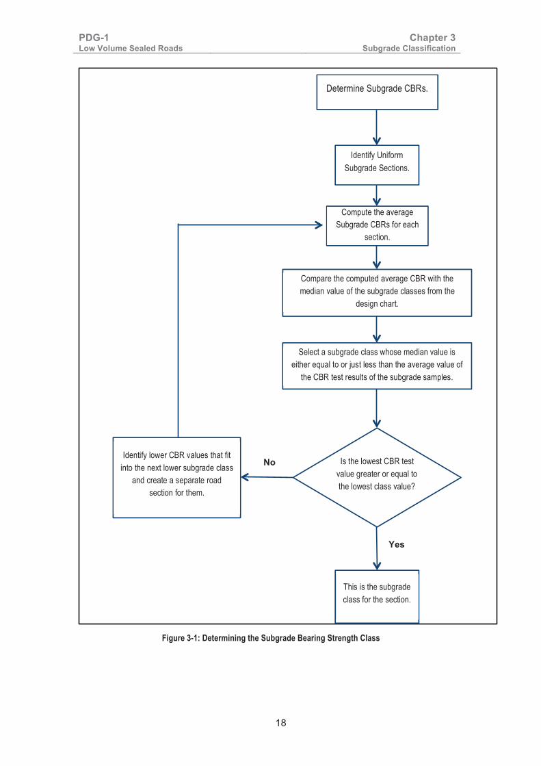
3.3 Determining Subgrade Bearing Strength Class The adopted subgrade bearing strength classes in Kenya are as shown in Table 3-2. The procedure for determining the subgrade class is shown in Figure 3-1.
Table 3-2: Subgrade CBR Bearing Strength Classes Subgrade Class CBR at 100% MDD AASHTO T99) and 4 days soak
������ �������
��� ������ ���
��� ������ ���
��� ������� ��
��� ����� � ���
��� ������� ����
��� ��� �
The CBR ranges correspond to the results actually obtained for materials of the same type, along sections of road considered to be homogeneous. They reflect the variations in the characteristics of the soil, even at small intervals, and the normal scatter of test results. The following points should be noted:-
(i) For any one section of road, the average CBR should be higher or equal to the mean of the subgrade class selected for design and no individual result shall be below the lowest value of the range for that subgrade class. Where the subgrade CBR values are very variable the designer should balance the cost of having very short uniform sections of different subgrade classes against a conservative design based on the worst condition encountered over longer sections.
(ii) No allowance for CBRs below 2% has been made. It is both technically and economically unacceptable to lay a pavement on soils of such poor bearing capacity. Such weak soils are saturated expansive clays, saturated fine silts or compressible (swampy) soils, such as mud, soft clay, etc. Indeed, the bearing strength of such soils is most uncertain

PDG-1 Low Volume Sealed Roads
Chapter 3 Subgrade Classification
17
and CBR values below 2% have little significance. They should be dealt with as described in the RDM III.
(iii) The use of class S1 soils as direct support for the pavement should be avoided as much as possible. Such poor quality soils should be excavated and replaced, or covered by an improved subgrade.
(iv) The CBR range of Class S5 is wide. Class S5 is either gravelly material or unsoaked soil, the CBRs of which always show considerable scatter. However, pavement thickness is not very sensitive to subgrade strength in this range and therefore the difference in pavement thickness required when the subgrade strength varies from the lower to the upper limit of the range is comparatively small.
(v) Class S6 covers all subgrade materials having a CBR greater than 30%. No subbase is required if the material complies with the plasticity requirements for natural sub-base materials.
�
� �
PDG-1 Low Volume Sealed Roads
Chapter 3 Subgrade Classification
18
�
Figure 3-1: Determining the Subgrade Bearing Strength Class
� �
Is the lowest CBR test value greater or equal to the lowest class value?
Determine Subgrade CBRs.
Identify Uniform Subgrade Sections.
Compare the computed average CBR with the median value of the subgrade classes from the
design chart.
Compute the average Subgrade CBRs for each
section.
Select a subgrade class whose median value is either equal to or just less than the average value of
the CBR test results of the subgrade samples.
Identify lower CBR values that fit into the next lower subgrade class
and create a separate road section for them.
This is the subgrade class for the section.
No
Yes

PDG-1 Low Volume Sealed Roads
Chapter 3 Subgrade Classification
19
3.4 Classification of the Most Common Kenyan Soils Table 3-3 shows typical classes of some Kenyan subgrade soils. These are not to be used for design purposes. The designer must obtain CBR values through laboratory tests. The table offers a means of cross-checking the results obtained.
Table 3-3: Classification of Kenyan Subgrade Soils
Type of Material CBR Bearing Strength Class
after 4-days soak At OMC (Standard)
Black cotton soil S1 S5
Micaceous silts (decomposed rock) S1 S3
Other alluvial silts (decomposed rock) S2 S4
Red friable clays S3 S5
Sandy clays on volcanics S3 or S4 S5
Ash and pumice soils1 S3 or S4 S5
Silty loams on gneiss and granite S4 S5
Calcareous sandy soils S4 S5
Sandy clays on basement S4 S5
Clayey sands on basement S4 or S5 S5 or S6
Dune sands S4 S4 or S5
Coastal sands S4 S5
Weathered lava S4 or S5 S5 or S6
Quartzitic gravels S4 – S6 S5 or S6
Soft (weathered) tuffs S4 – S6 S5 or S6
Calcareous gravels S4 – S6 S5 or S6
Lateritic gravels S5 or S6 S6
Coral gravels S5 or S6 S6
������������������������������������ ����!��!�"#� �$���%������"#�������#������� �$�"�&���'(�� )��� ��� ����� ��'��� *�� �%������� �"��� ���� �����"��� +,-� !� ���� ����� ��� ��.������"�� +���������� )//� ���� ����� ��� )'0��1� ������� *�� � ��������� ��"� ��!����������'����"�������������*��������+,-��� #�
3.5 Rapid Determination of Homogenous Subgrade Sections The DCP may also be used to rapidly identify homogenous sections and to provide useful information about layer thicknesses, thus allowing the designer to estimate:
(i) the quantity of a better quality layer that can be mixed with existing subgrade material to obtain an improved subgrade; and,
(ii) the thickness of an existing layer that can be treated as a capping layer.
PDG-1 Low Volume Sealed Roads
Chapter 3 Subgrade Classification
20
The tool should be driven to a minimum depth of 800 mm below any measurement surface. The DCP-CBR to be used in the computation for identification of uniform sections shall be the weakest DCP-CBR below the depth at which any improvement will stop. Operating instructions of the Dynamic Cone Penetrometer are found in TRL publication number PR/INT/277/04, which is available freely online.
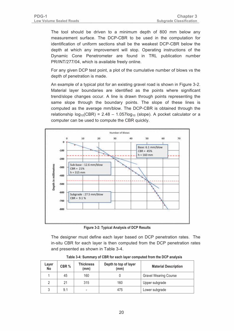
For any given DCP test point, a plot of the cumulative number of blows vs the depth of penetration is made.
An example of a typical plot for an existing gravel road is shown in Figure 3-2. Material layer boundaries are identified as the points where significant trend/slope changes occur. A line is drawn through points representing the same slope through the boundary points. The slope of these lines is computed as the average mm/blow. The DCP-CBR is obtained through the relationship log10(CBR) = 2.48 – 1.057log10 (slope). A pocket calculator or a computer can be used to compute the CBR quickly.
Figure 3-2: Typical Analysis of DCP Results
The designer must define each layer based on DCP penetration rates. The in-situ CBR for each layer is then computed from the DCP penetration rates and presented as shown in Table 3-4.
Table 3-4: Summary of CBR for each layer computed from the DCP analysis
Layer No CBR % Thickness
(mm) Depth to top of layer
(mm) Material Description
1 45 160 0 Gravel Wearing Course
2 21 315 160 Upper subgrade
3 9.1 - 475 Lower subgrade

PDG-1 Low Volume Sealed Roads
Chapter 3 Subgrade Classification
21
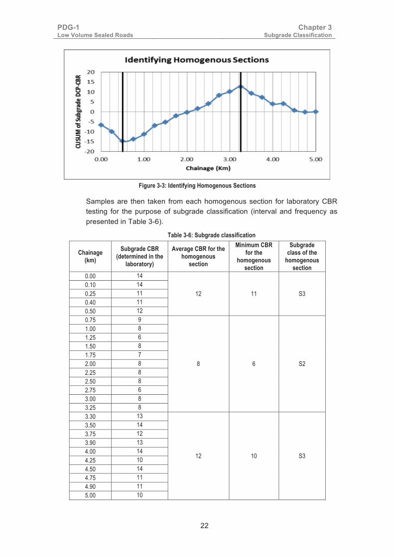
The in-situ CBR values of the subgrade layer along the road are computed from the DCP measurements and tabulated by chainage as shown in Table 3-5. The average of all the readings along the road is computed. The difference of each CBR value from the average is also computed and summed cumulatively (CUSUM) along the chainages until the final chainage. A plot of the CUSUM against the chainage is then made as shown in Figure 3-3. Points at which there are significant changes in slope of the CUSUM represent changes from one homogeneous section to the next. In this case three homogenous sections occur: Chainage 0 to 0.5 km, Chainage 0.5 to 3.25 km, and Chainage 3.25 to 5.0 km.
Table 3.5 Determination of CUSUM
Chainage Penetration rate mm/blow
Measured CBR
Average CBR – Measured CBR CUSUM
0.00 12 22 -7 -7 0.25 14 19 -3 -10 0.50 13 20 -5 -15 0.75 18 14 1 -14 1.00 20 13 3 -11 1.25 23 11 4 -7 1.50 19 13 2 -5 1.75 21 12 3 -2 2.00 19 13 2 0 2.25 19 13 2 2 2.50 20 13 3 4 2.75 23 11 4 8 3.00 19 13 2 10 3.25 20 13 3 13 3.50 14 19 -3 9 3.75 15 17 -2 7 4.00 14 19 -3 4 4.25 17 15 0 4 4.50 14 19 -3 1 4.75 16 16 -1 0 5.00 17 15 0 0
Average CBR 15
�
�
PDG-1 Low Volume Sealed Roads
Chapter 3 Subgrade Classification
22
Figure 3-3: Identifying Homogenous Sections
Samples are then taken from each homogenous section for laboratory CBR testing for the purpose of subgrade classification (interval and frequency as presented in Table 3-6).
Table 3-6: Subgrade classification
Chainage (km)
Subgrade CBR (determined in the
laboratory)
Average CBR for the homogenous
section
Minimum CBR for the
homogenous section
Subgrade class of the
homogenous section
0.00 14
12 11 S3 0.10 14 0.25 11 0.40 11 0.50 12 0.75 9
8 6 S2
1.00 8 1.25 6 1.50 8 1.75 7 2.00 8 2.25 8 2.50 8 2.75 6 3.00 8 3.25 8 3.30 13
12 10 S3
3.50 14 3.75 12 3.90 13 4.00 14 4.25 10 4.50 14 4.75 11 4.90 11 5.00 10

PDG-1 Low Volume Sealed Roads
Chapter 4 Pavement Foundation
23
Chapter 4: Pavement Foundation
4.1 Introduction The foundation is the platform on which the pavement is constructed. It comprises either:
(i). The top 300 mm of the subgrade below the formation in embankments or cuttings constructed using material complying with the bearing strength requirement of the selected foundation class in two layers of 150 mm thickness compacted to 100% MDD (AASHTO T99); or,
(ii). Where the subgrade material is not complying with the strength requirements of the selected foundation class, the upper 300 mm of the subgrade completed in 150mm compacted layers and the capping.
The foundation classes are defined in terms of the surface stiffness modulus at equilibrium moisture and are presented in Table 4-1.
Table 4-1: Pavement Foundation Classes
Foundation Class
Minimum Surface Stiffness Modulus (MPa)
Minimum CBR at 100% MDD (AASHTO T99) and 4 days soak
(%)
Equivalent Subgrade Class
F1 65 10 S3
F2 90 14 S4
F3 125 23 S5
F4 250 30 S6
F5 400 80
4.2 Suitable Subgrade Materials for Pavement Support Where the subgrade material does not comply with the strength requirements of the selected foundation class a capping layer shall be constructed to improve the subgrade.
In low-lying areas and in areas of expansive subgrades, fills are generally necessary to attain the required geometric design requirements, minimise the effect of expansive subgrades on the upper pavement layers, and to minimise the risk of the pavement being over-topped during floods.
In situ subgrade in cuttings or fill material placed below the capping layers shall comply with the following minimum requirements: • A minimum CBR of 3% at 100% MDD (AASHTO T99) and 4-days soak. • Swell at 100% MDD (AASHTO T99) and 4-day soak of less than 2%. • Plasticity index less than 50%. • Organic matter (percentage by weight) of less than 3%. • Soft material as fill shall be deposited in layers not exceeding 150 mm
compacted depth.

PDG-1 Low Volume Sealed Roads
Chapter 4 Pavement Foundation
24
Rock fill can be used provided that boulders greater than 0.2 m3 (600 mm size) are not used and that this material is not placed within 600 mm of the formation level. The best materials either from cuttings or from borrow areas, should be reserved for upper fill layers or capping layers.
4.3 Unsuitable Materials
4.3.1 Rock Outcrops Where rock outcrops are encountered the alignment should be changed if space limitations do not prevail. If space limitations exist, a fill or a cut through the outcrop may be required to achieve the vertical alignment requirements. Though the rock may exceed the strength requirements of the pavement layers, the surface is often uneven and may not enable achievement of uniform compaction of the overlying layer. Further, the irregularities are also likely to be reflected on the completed pavement after some years of trafficking. A regulating or cushioning layer using granular material complying with the pavement foundation requirements of at least 300mm compacted thickness is recommended before pavement construction.
Blinding of the outcrops if not exceeding 150mm using Class 20 concrete may also be considered by the design Engineer as an alternative to rock cut.
4.3.2 Swampy Areas A swamp is water logged low lying ground which receives continuous inflow of water from either a stream or a ground water source. Swampy areas usually contain vegetation and soft soil deposits such as peats, organic and inorganic silts and clays. The soil deposits are highly compressible and susceptible to large settlements and deformations.
Construction of a road embankment on such areas requires geotechnical investigations to determine the treatment options. The field investigations methods may include trial pitting and/or drilling to extract disturbed and undisturbed samples for soil classification, bearing strength tests and to determine settlement parameters.
Methods of embankment construction may include any or a combination of the following options:
(a) Preloading by full or stage construction
Preloading by direct construction of an embankment is a common way of pre-stressing soft soil to consolidate the soft material. If an embankment is properly constructed on a soft subsoil, the subsoil will compress considerably, its moisture content will decrease and its dry density and shear strength will increase.
Settlement may be accelerated using either, or a combination of, a preloading/surcharge and sand drains.
(b) Excavation and displacement

PDG-1 Low Volume Sealed Roads
Chapter 4 Pavement Foundation
25
Removing the problem soil and replacing it with a more stable material or displacement of very watery material by introducing coarse rock fill.
(c) Use of lightweight materials
Minimising settlement by reducing the weight of the embankment using light materials such as cinder, and fly ash.
(d) Use of geotextiles
Geotextiles are non-decomposable synthetic fabric materials made of nylon, polyester, and poly propylene and may be used for physical separation of layers, filtering medium, and for the reinforcement of the weak soils.
(e) Use of Geogrids
Geogrids are high strength plastic grids which are interposed either at the bottom of a layer or in a layer itself to increase the load bearing capacity of the soil.
4.3.3 Expansive Clays Comparatively large areas of Kenya are covered with expansive clays, commonly known as "black cotton soils”. These soils exhibit significant volume changes when wetted or dried. Typical damage to roads on expansive soils includes longitudinal unevenness and bumpiness, differential movement near culverts and longitudinal cracking.
Expansive soils generally owe their expansive characteristics to their constituent clay minerals especially montmorillonite and to their natural and imposed environments. It is believed that the primary source of residual expansive clay soils is the in-situ weathering of basic igneous, metamorphic and pyroclastic rocks, which occur in abundance in Kenya. Typically they form in flat, poorly drained environments which favour the formation of expansive soil minerals.
Expansive clay subgrades may be identified in the field by observation of large cracks that appear on the land surface in the dry season and disappear in the wet season. After desiccation the surface exhibits polygonal shrinkage cracks, which reflect the percentage of clay and possibly the presence of expandable clay minerals.
In the laboratory these soils are identified using index properties, bearing strength and swell tests. Experience has shown that the volume change behaviour correlates reasonably well with liquid limit, plasticity index and shrinkage limit.
For instance, if the liquid limit is above 70%, then the material is often highly expansive and may not be suitable for fills. If the liquid limit is between 40% and 70%, then some treatment may be necessary to avoid distress. Similarly, plasticity index is also a useful indicator; values below 15% indicate minimal

PDG-1 Low Volume Sealed Roads
Chapter 4 Pavement Foundation
26
problems and values greater than 35% indicate that the material must be treated or discarded.
The swell test is the second and most direct method for measurement of volume change, providing swell and swell pressure values. The swell defines deformation, while the swelling pressure is related to stress generated by volume change. The Oedometer swell test with minimum surcharge may be used to determine volume change. However, for practical design purposes, the CBR swell test may be used. Expansive clays will exhibit swell exceeding 3%.
The four common approaches for dealing with expansive clay subgrades, as detailed in Chapter 11 of RDM Part III, are as follows:
(i). Avoid the areas of expansive clays by realigning the road.
(ii). Excavate and replace the expansive clays with suitable material.
(iii). Treat the expansive clay with lime.
(iv). Minimise moisture changes in the clay to avoid detrimental volume changes in the material.
The design engineer is advised to carry out a cost-benefit analysis before selecting a suitable approach. Although not always the case, Option 4 (minimising volume changes) is usually the most cost-effective for LVSR and involves:
• Confining expansive clays under a capping of compacted thickness of at least 300mm using soils having CBR of at least 10% (G10);
• Construction of an embankment of at least 1.0 m as surcharge to reduce swell comprising:-
− The upper embankment, consisting of the pavement and the capping, having a total thickness of at least 600mm; and,
− Lower embankment, which may also be formed using expansive soils, having a total thickness of at least 400mm.
• Limiting the compaction of layers with expansive clays to 98% of MDD (AASHTO T99).
• Processing/placing expansive clays at equilibrium moisture levels (EML) or at Optimum Moisture Content (AASHTO T99) where the EML cannot be established;
• Preventing moisture changes under the pavement by providing sealed shoulders of at least 0.5m width and minimum side slopes of 1:4.
It is advisable to use only flexible pavements on expansive clays. Rigid pavements are not recommended as they often fracture under slight movements. Impermeable bedding should be provided on expansive clays before placement of culverts.

PDG-1 Low Volume Sealed Roads
Chapter 4 Pavement Foundation
27
4.3.4 Dispersive Soils Dispersive soils are those soils that, when placed in water, have repulsive forces between the clay particles that exceed the attractive forces. This results into the colloidal fraction going into suspension. In moving water, the dispersed particles are carried away or eroded. This obviously has serious implications in earth dam construction but is of less consequence in road construction. However, inclusion of dispersive soils in the subgrade or fill can lead to significant pavement failures through piping, tunnelling, and the formation of cavities.
Dispersive soils often develop in low-lying areas with gently rolling topography and relatively flat slopes. In Kenya dispersive soils occur in Mai Mahiu, Suswa, and Lake Turkana areas.
It is important to identify dispersive soils prior to design. In areas of sloping topography where dispersive soils exist, a characteristic pattern of surface erosion is evidenced by jagged, sinuous ridges and deep rapidly forming channels and tunnels.
In the laboratory, dispersive soils may be identified in the following ways:
• When a sample of the soil is placed in a jar of distilled water, it forms a cloudy suspension with a ring of particles at the water surface and around larger lumps.
• Another early indication of potentially dispersive soils is that the CBR test gives low strengths, less than 3%, however, this is not a confirmatory test.
• Confirmatory tests in the laboratory include a combination of pedological tests such as Exchangeable Sodium Percentage (ESP) based tests, Pinhole Test, Crumb Test, Double Hydrometer Test, pH, and Dissolved Salts in the pore water test.
From a road engineering perspective, field observation and the first two tests are sufficient guide in deciding whether the soil/subgrade needs special treatment.
The remedial measures applicable on dispersive soils are as follows:
• Adopt designs that minimise the need for excavation and subsoil exposure, and disturbance to topsoil and vegetation.
• Cover dispersive soils with a minimum 100mm layer of non-dispersive soil prior to re-vegetation or placement of the pavement layers.
• Avoid its use in fills as much as possible.
• Remove and replace it in the upper 300mm of the subgrade.
• Top dress the surface of potentially dispersive soils with up to 2% gypsum if soil pH > 6.5 or up to 4% lime if soil pH < 5.0 or a mixture of both if soil pH is between 5.0 and 6.5. The use of gypsum is

PDG-1 Low Volume Sealed Roads
Chapter 4 Pavement Foundation
28
recommended over lime, as lime may lead to soil stabilisation and its associated cracking.
• Manage water flows and drainage in the area well.
• Infill any trenches or holes to prevent collection and ponding of water on subsoil surfaces.
4.3.5 Collapsible Soils Collapsible soils are those that appear to be strong and stable in their natural dry state but which rapidly consolidate under wetting, generating large and often unexpected settlements. Such soils include loess and windblown silts generally consisting of 50 to 90% silt particles.
Often, the loose structure of these soils is held together by small amounts of clay minerals or calcium carbonate. The introduction of water dissolves the bonds created by these cementing materials and allows the soil to take a denser packing under any type of compressive loading. The condition for collapse is that the soil mass must be in a partially saturated condition and then wetted up and loaded simultaneously which can occur beneath pavement structures.
Collapsible soils possess porous textures with high void ratios and relatively low densities. They often have sufficient void space in their natural states to hold their liquid moisture at saturation.
In the laboratory the potential degree of collapse is best determined using the oedometer test. The double oedometer test for assessing the response of a soil for wetting and loading at different stress levels should be carried out. The designer should obtain information on general location of collapsible soils in Kenya from MTRD and only carry out confirmatory investigations where the project road traverses such areas.
Remedial measures include:
• Moistening and using high energy compaction techniques using large impact rollers to reduce the collapse potential.
• Ground modification involving either partial removal and replacement or densification of the collapsible soil using techniques such as compaction grouting and pre-wetting of the soil followed by a surcharge loading to cause settlement before construction.
4.4 Design of Improved Subgrade If the material in cuttings or embankments does not meet the requirements of the selected foundation class, a capping layer shall be constructed to improve the subgrade to achieve the design foundation class.

PDG-1 Low Volume Sealed Roads
Chapter 4 Pavement Foundation
29
The improvement is designed to bring the existing native subgrade plus the capping layers up to an overall bearing strength level equivalent to that of the selected foundation.
Placing a capping layer to improve the subgrade not only increases the bearing strength of the direct support for the pavement, but also;
• Protects the upper layers of the earthworks against adverse weather conditions.
• Facilitates the movement of construction traffic.
• Assists with obtaining good compaction of the pavement layers.
• Reduces the variation in subgrade bearing strength.
• Prevents the contamination of open-textured sub-bases by plastic fines from the natural subgrade.
The minimum thickness of each type of capping material required to improve the subgrade to a higher class is shown in table 4-2. The minimum thicknesses have been calculated taking into account the respective elastic modulus of each class of soil.

PDG-1 Low Volume Sealed Roads
Chapter 4 Pavement Foundation
30
Table 4-2 Minimum Capping Thicknesses for Improved Subgrade Native
Subgrade Class
Capping Improved/New Subgrade
Class Layer 1 Layer 2
Material Thickness (mm)
Material Thickness (mm)
S1
G8 300 S2
G10 275 S2
G8 200 G15 150 S3
G8 175 G20 150 S3
G10 350 S3
G10 175 G15 150 S3
G10 150 G20 150 S3
G8 275 G15 150 S4
G8 250 G20 150 S4
G10 225 G20 150 S4
G10 200 G30 150 S4
G10 300 G25 175 S5
G10 275 G30 175 S5
G10 325 G30 175 S6
S2
G10 100 S3
G15 175 S4
G20 150 S4
G25 150 S4
G25 200 S5
G30 225 S6
S3
G15 100 S4
G20 100 S4
G25 150 S5
G30 175 S6
S4 G25 100 S5
G30 125 S6
S5 G30 100 S6
Capping materials shall be compacted as follows:
i). G8 and G10: in layers not exceeding 150mm to a dry density of at least 100% MDD (AASHTO T99); and,
ii). G15, G20, G25 and G30: in layers not exceeding 200mm to a dry density of at least 95% MDD (AASHTO T180)

PDG-1 Low Volume Sealed Roads
Chapter 5 Pavement Materials
31
Chapter 5: Pavement Materials
5.1 Introduction The selection of materials for a road pavement design is based on a combination of availability of suitable materials, environmental considerations, method of construction, economics and previous experience. These factors need to be evaluated during the design in consideration of the Life Cycle Strategy, in order to select the materials that best suit the conditions.
5.2 Classification of Materials The materials are classified as follows:
(i) Natural or blended (Mechanically Stabilised) granular materials coded with the letter “G”, followed by a number denoting the minimum CBR strength measured after 4 days soak on the sample moulded and compacted at OMC to the densities specified in the individual materials charts in section 5.13;
(ii) Hydraulically Improved Granular materials (Cement/HRB/Lime) coded with letters “HIG”, followed by a number denoting the minimum CBR strength measured after 7 days cure and 7 days soak on a mix compacted to at least 95% MDD (AASHTO T180);
(iii) HRB denotes Hydraulic Road Binder complying with BS EN 13282-1;
(iv) Bitumen Emulsion Stabilised Materials coded with letters BESM, followed by a number denoting the minimum indirect tensile strength tested after 7 days of curing and 7 days of soaking;
(v) HPS denotes Hand Packed Stone;
(vi) ICS/CPB denotes Interlocking Cobble Stone/Concrete Paving Block Surfacing;
(vii) Concrete Pavement is denoted by “CP”, followed by the unconfined compressive strength in MPa after 28 days of curing.
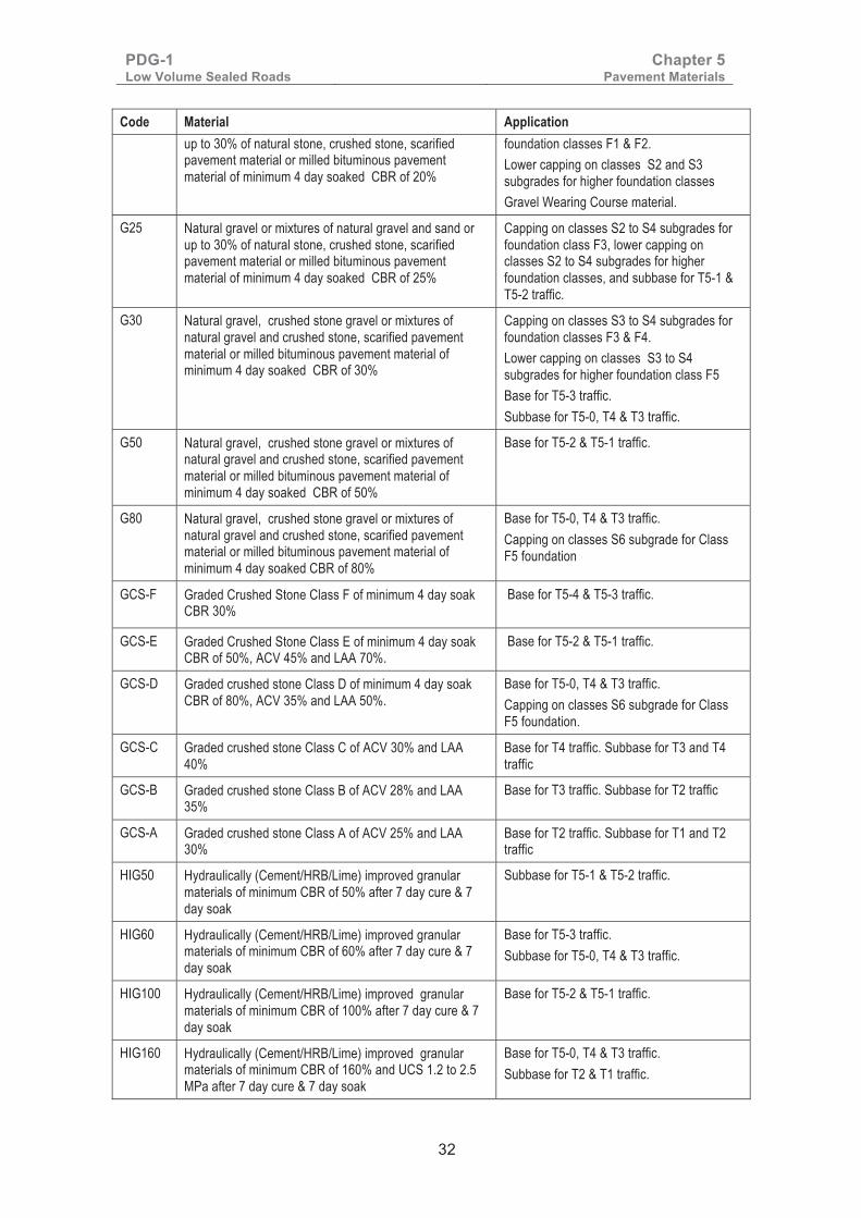
The materials for capping and pavement structures have been classified as indicated in Table 5-1 and detailed in sub-section 5.13: Material Specification Charts.
Table 5-1: Specifications for Capping and Pavement Materials
Code Material Application
G8 Natural or blended silty, sandy or gravelly clays of minimum 4 day soaked CBR of 8%
Lower capping on class S1 subgrade
G10 Natural or blended silty, sandy or gravelly clays, silty and clayey sands, sands, or gravels of minimum 4 day soaked CBR of 10%
Capping on classes S1 & S2 subgrades for Class F1 foundation. Lower capping on classes S1 & S2 subgrades for higher foundation classes
G15 Natural or blended silty and clayey sands, sands, or gravels of minimum 4 day soaked CBR of 15%
Capping on classes S2 to S3 subgrades for Classes F1 & F2 foundations. Lower capping on classes S2 to S3 subgrades for higher foundation classes
G20 Natural gravel or mixtures of natural gravel and sand or Capping on classes S2 and S3 subgrades for
PDG-1 Low Volume Sealed Roads
Chapter 5 Pavement Materials
32
Code Material Application up to 30% of natural stone, crushed stone, scarified pavement material or milled bituminous pavement material of minimum 4 day soaked CBR of 20%
foundation classes F1 & F2. Lower capping on classes S2 and S3 subgrades for higher foundation classes Gravel Wearing Course material.
G25 Natural gravel or mixtures of natural gravel and sand or up to 30% of natural stone, crushed stone, scarified pavement material or milled bituminous pavement material of minimum 4 day soaked CBR of 25%
Capping on classes S2 to S4 subgrades for foundation class F3, lower capping on classes S2 to S4 subgrades for higher foundation classes, and subbase for T5-1 & T5-2 traffic.
G30 Natural gravel, crushed stone gravel or mixtures of natural gravel and crushed stone, scarified pavement material or milled bituminous pavement material of minimum 4 day soaked CBR of 30%
Capping on classes S3 to S4 subgrades for foundation classes F3 & F4. Lower capping on classes S3 to S4 subgrades for higher foundation class F5 Base for T5-3 traffic. Subbase for T5-0, T4 & T3 traffic.
G50 Natural gravel, crushed stone gravel or mixtures of natural gravel and crushed stone, scarified pavement material or milled bituminous pavement material of minimum 4 day soaked CBR of 50%
Base for T5-2 & T5-1 traffic.
G80 Natural gravel, crushed stone gravel or mixtures of natural gravel and crushed stone, scarified pavement material or milled bituminous pavement material of minimum 4 day soaked CBR of 80%
Base for T5-0, T4 & T3 traffic. Capping on classes S6 subgrade for Class F5 foundation
GCS-F Graded Crushed Stone Class F of minimum 4 day soak CBR 30%
Base for T5-4 & T5-3 traffic.
GCS-E Graded Crushed Stone Class E of minimum 4 day soak CBR of 50%, ACV 45% and LAA 70%.
Base for T5-2 & T5-1 traffic.
GCS-D Graded crushed stone Class D of minimum 4 day soak CBR of 80%, ACV 35% and LAA 50%.
Base for T5-0, T4 & T3 traffic. Capping on classes S6 subgrade for Class F5 foundation.
GCS-C Graded crushed stone Class C of ACV 30% and LAA 40%
Base for T4 traffic. Subbase for T3 and T4 traffic
GCS-B Graded crushed stone Class B of ACV 28% and LAA 35%
Base for T3 traffic. Subbase for T2 traffic
GCS-A Graded crushed stone Class A of ACV 25% and LAA 30%
Base for T2 traffic. Subbase for T1 and T2 traffic
HIG50 Hydraulically (Cement/HRB/Lime) improved granular materials of minimum CBR of 50% after 7 day cure & 7 day soak
Subbase for T5-1 & T5-2 traffic.
HIG60 Hydraulically (Cement/HRB/Lime) improved granular materials of minimum CBR of 60% after 7 day cure & 7 day soak
Base for T5-3 traffic. Subbase for T5-0, T4 & T3 traffic.
HIG100 Hydraulically (Cement/HRB/Lime) improved granular materials of minimum CBR of 100% after 7 day cure & 7 day soak
Base for T5-2 & T5-1 traffic.
HIG160
Hydraulically (Cement/HRB/Lime) improved granular materials of minimum CBR of 160% and UCS 1.2 to 2.5 MPa after 7 day cure & 7 day soak
Base for T5-0, T4 & T3 traffic. Subbase for T2 & T1 traffic.

PDG-1 Low Volume Sealed Roads
Chapter 5 Pavement Materials
33
Code Material Application
BESM 3 Bitumen Emulsion Stabilised Material of minimum soaked ITS of 50 kPa.
Base for T5-2, T5-1 & T5-0 traffic.
HPS 150mm and 200mm Hand Packed Stone of maximum ACV of 35%
Base for T5-0
ICS/ CPB
Interlocking Cobble Stone/ Concrete Paving Block Surfacing
Base/Surfacing for T5-2, T5-1 & T5-0 traffic.
CP25 Class 25 Cement Concrete Surfacing Base/Surfacing for T5-2, T5-1 & T5-0 traffic.
5.3 Natural Materials A wide range of natural materials including lateritic, quarzitic and calcareous gravels, soft stones, coral rags, conglomerates, silty and clayey sands, or a combination of any of these materials, can be used successfully as road subbase and base materials. Where natural materials do not meet the material specifications, the designer is urged to explore blending (mechanical stabilisation) as an alternative before resorting to chemical or bitumen stabilisation. The use of fine crushed stone aggregates to improve the bearing strength and reduce the plasticity of the materials is encouraged. The plasticity of coarse non-plastic materials should be improved by adding plastic material, such as clayey soil.
Natural materials for capping and pavement purposes are categorised as G8, G10, G15, G20, G25, G30, G50 and G80.
Detailed specifications of each of the materials are provided in charts GM1 (G8), GM2 (G10), GM3 (G15), GM4 (G20), GM5 (G25), GM6 (G30), GM7 (G50), and GM8 (G80). The specifications may also be economically achieved by mechanical stabilisation using different types of natural materials or up to 30% of crushed stone aggregates, scarified pavement material or milled bituminous pavement material.
The materials for capping are mostly G8, G10, G15, G20 and G25. It is important that capping materials possess low swell so as to minimise risks of pavement failure through expansion due to moisture ingress. All capping materials should be compacted as specified in the materials charts.
The capping material directly supporting a pavement should not have a plasticity index exceeding 30%. For the case of a capping layer provided over S1 subgrade (usually expansive soils), a minimum plasticity index is specified to ensure that the subgrade is protected from moisture ingress from precipitation during construction, or in case of failure of the upper pavement layers. Granular materials G15 and above should not be constructed directly on S1 to comply with the modular ratio requirements explained in section 6.5.
Granular materials for sub-base and base use are specified in charts GM5 (G25), GM6 (G30), GM7 (G50), and GM8 (G80).

PDG-1 Low Volume Sealed Roads
Chapter 5 Pavement Materials
34
With respect to materials specification charts for materials G20 (GM 4) and G25 (GM 5), wet climate refers to areas that receive more than 500 mm of rainfall per annum, and dry climate refers to any areas that receive less than 500 mm of rainfall per annum.
5.4 Graded Crushed Stone Stone is abundant in many parts of the country and graded crushed stone (GCS) may be used as a pavement material, particularly where suitable natural gravel cannot be found. This is an expensive option for LVSRs and should only be considered where no cheaper materials options exist.
The material requirements, traffic application and construction procedures are summarised in Chart GM9 for the following classes:
• Graded Crushed Stone Class A (GCS-A)
• Graded Crushed Stone Class B (GCS-B)
• Graded Crushed Stone Class C (GCS-C)
• Graded Crushed Stone Class D (GCS-D)
• Graded Crushed Stone Class E (GCS-E)
• Graded Crushed Stone Class F (GCS-F)
GCS classes A, B and C must be at least semi-crushed, whereas rounded aggregate (alluvial deposits) may be accepted for classes D, E and F. In general, GCS should be mixed and moistened in a stationary plant and laid by paver to comply with the required specifications.
Stationary mixing and moistening may not be economical for GCS for LVSR. The grading envelope for subbase for medium and low volume traffic usually cover the crusher-runs obtained and therefore crusher-run should be used as much as possible. GCS for base for LVSRs should be mixed in a stationary plant to achieve the grading specifications. However, moistening may be done in place and the material spread by grader to minimise construction costs.
The compaction of GCS and hence its performance is dependent on the bearing strength of the supporting layer. It is therefore essential that the supporting layer is adequately compacted before placing and compaction of GCS. To achieve the required level of compaction, the following are recommended:
• Compact the supporting layer to higher achieve densities higher than the minimum specification; and,
• Ensure that the supporting layer is at optimum moisture content before placing and compaction of the GCS.
Water Bound Macadam (WBM) and Dump Rock (DR) on the other hand may be constructed using a grader in-situ and as such may be cheaper to construct than GCS. WBM consists of a stone skeleton of single-sized coarse

PDG-1 Low Volume Sealed Roads
Chapter 5 Pavement Materials
35
aggregate in which the voids are filled with finer material. The stone skeleton contains considerable voids that are filled by fine aggregate, which in turn is washed or ‘slushed’ into the coarse skeleton with water. DR consists of coarser particles than WBM and is used mainly as fill material.
5.5 Hydraulically Improved Granular Materials Natural granular materials are widely available, however, in most cases their strength and plasticity characteristics do not meet specifications. In such cases the materials can be improved using cement, Hydraulic Road Binders (HRBs) or lime, depending on the properties of the natural material.
HRBs are cementitious powders made from Portland cement clinker and other constituents such as natural pozzolana, natural calcined pozzolana, limestone, siliceous fly ash, calcareous fly ash, burnt shale, cement kiln dust and retarders.
It is essential to distinguish between hydraulically improved materials and cement stabilised materials.
Improvement consists of treating materials with lime, HRB or with a comparatively small amount of cement, so that the engineering characteristics are improved (higher bearing strength, lower plasticity), but the treated material remains flexible with the load bearing characteristics being predominantly inter-particle friction and aggregate interlock.
Stabilisation on the other hand consists of treating materials with sufficient amount of cement so that their cohesion is considerably increased and significant rigidity is obtained, resulting in a rigid or semi rigid pavement with mortar strength being the predominant load bearing characteristic.
The characteristics of the materials to be treated with cement or lime should be as specified in Charts HIG-1, HIG-2, HIG-3 and HIG-4. In cases where the material to be treated has a plasticity index of more than 20 and the percentage of the fraction finer than 75 µm is greater than 25%, cement should not be used as the only modifier; pre-treatment with lime is required before subsequent treatment with cement is applied. The material should be mixed with lime and allowed 24 hours to cure, before mixing with cement and final compaction is carried out. Lime should not be used for modification of materials that have a plasticity index less than 10%.
In adverse circumstances carbon dioxide may react with hydration products of lime and cement-stabilised materials, causing a loss in strength. The main modes of distress caused by carbonation of stabilised layers are loosening of unsurfaced or primed layers and loss of bond between the stabilised layer and any layer above. The risk of carbonation can be reduced by ensuring that the quantity of lime or cement used exceeds the initial consumption of lime/cement and the pH of the stabilised material is greater than 12.4. Curing of the stabilised material should be such that the material is kept constantly moist and repeated cycles of wetting and drying are avoided. The layer

PDG-1 Low Volume Sealed Roads
Chapter 5 Pavement Materials
36
should also be sealed immediately after curing. It must also be borne in mind that if much higher strengths are achieved by initial stabilisation, carbonation may not adversely affect the strength of the modified material.
The initial consumption of lime (ICL) or cement (ICC) test determines the quantity of lime or cement required to react with any material to be stabilised and to maintain a pH of 12.4. It has been determined through studies that this is the minimum pH value required in order for the reaction between reactive components of the material and stabiliser to be sustained. The test method to be used is BS1924-2:1990. This test involves mixing samples of the material with water and different proportions of the stabiliser. The percentage of stabiliser required to achieve a pH of 12.4 is determined through graphing.
5.6 Bitumen Stabilised Materials The guidance given in this sub-section is based on the manual Asphalt Academy (2009).
Bitumen Stabilised Materials (BSMs) are pavement materials that are treated with either bitumen emulsion or foamed bitumen. The materials treated are normally granular materials, previously cement treated materials or reclaimed asphalt layers.
The use of bitumen stabilised materials (BSM) is preferred for pavement rehabilitation interventions as it allows utilisation of existing pavement materials and immediate passage of traffic. BSM layers are also less susceptible to weaknesses in the underlying layers compared to cement or bitumen bound layers.
The quantities of residual bitumen emulsion or foamed bitumen added do not typically exceed 3% by mass of dry aggregate. In many situations, active filler in the form of cement or hydrated lime is also added to the mix. The cement content should not exceed 1%, and should also not exceed the percentage of the bitumen stabiliser, (i.e. the ratio of bitumen percentage to cement percentage should always be greater than 1). If this ratio is less than one, then the material should be considered as a cement improved material under section 5.5.
The types of filler used are cement (various types, but not rapid hardening cements), lime, rock flour, fly ash and slagment. For the purpose of this guideline, the term active filler is used to define fillers that chemically alter the mix properties. This includes fillers such as lime, cement and fly ash but excludes natural fillers such as rock flour. In this guideline, lime always refers to hydrated lime.
The purpose of incorporating active filler in BSM is to:
• Improve adhesion of the bitumen to the aggregate. • Improve dispersion of the bitumen in the mix. • Modify the plasticity of the natural materials (reduce PI). • Increase the stiffness of the mix and rate of strength gain.

PDG-1 Low Volume Sealed Roads
Chapter 5 Pavement Materials
37
• Accelerate curing of the compacted mix.
The addition of bitumen emulsion or foamed bitumen to produce a BSM results in an increase in material strength and a reduction in moisture susceptibility as a result of the manner in which the bitumen is dispersed amongst the finer aggregate particles. Such “non-continuous” binding of the individual aggregate particles makes BSMs different from all other pavement materials. The dispersed bitumen changes the shear properties of the material by significantly increasing the cohesion value, whilst effecting little change to the internal angle of friction. A compacted layer of BSM will have a void content similar to that of a granular layer, and not to an asphaltic material. BSMs are therefore granular in nature and are treated as such during construction.
The primary benefits of using BSMs are:
• The increase in strength associated with bitumen treatment allows a BSM to replace alternative high-quality materials in the upper pavement. For example, a G80 quality material treated with either bitumen emulsion or foamed bitumen can be used in place of an asphalt base, provided it meets the layer requirements, thereby offering significant cost savings.
• Improved durability and moisture insensitivity due to the finer particles being encapsulated in bitumen and thereby immobilised.
• Lower quality aggregates can often be successfully used.
• The typical failure mode of a BSM (permanent deformation) implies that the pavement will require far less effort to rehabilitate when the terminal condition is reached, compared to a material that fails due to full-depth cracking.
• BSMs are not temperature sensitive, unlike hot mix asphalt. This is because the bitumen is not continuous throughout the mix.
• Unlike a hot mixed asphalt, BSMs are not overly sensitive materials. Small variations in both the amount of bitumen added and untreated material properties will not significantly change the strength achieved through treatment. This allows the inevitable variability in the recycled material to be tolerated.
• Traffic disruption and time delays are minimised by working in half widths and opening to traffic soon after completion. The construction and maintenance of diversions is therefore avoided.
• Pavements showing a wide range of distress types can be effectively rehabilitated, thus eliminating most of the heavy construction traffic that damages newly constructed layers and adjacent access and service roads.
The BSMs are classified into following three classes:

PDG-1 Low Volume Sealed Roads
Chapter 5 Pavement Materials
38
• BSM1: Bitumen emulsion/foamed bitumen stabilised graded crushed stone or reclaimed asphalt used as a base layer for design traffic applications of more than 6 million equivalent standard axles (MESA).
• BSM2: Bitumen emulsion/foamed bitumen stabilised graded natural gravel or reclaimed asphalt used as a base layer for design traffic applications of less than 6 MESA.
• BSM3: Bitumen emulsion/foamed bitumen stabilised gravels or clayey/silty sands, stabilised with higher bitumen contents suitable as a base layer for design traffic applications of less than 1 MESA.
The mix design procedure consists of:
1. Preliminary tests:
These include standard laboratory tests to determine the grading curve, moisture, density relationships and Atterberg limits. Where the results indicate that some form of pre-treatment is required, additional tests must be undertaken after such pre-treatment to ensure that the desired results are achieved.
2. Level 1 Mix Design:
Level 1 starts with the preparation of samples that will be used to manufacture the specimens required for all levels of mix design testing. 100 mm diameter specimens (Marshall briquette) are compacted and cured for Indirect Tensile Strength (ITS) testing. Test results are used to identify the preferred bitumen stabilising agent, determine the optimum bitumen content and to identify the need for filler, and, where required, the type and content of filler.
Level 1 mix design is sufficient for lightly trafficked pavements, which will carry less than 3 MESA (BSM2 and BSM3).
3. Level 2 Mix Design:
This level uses 150 mm diameter by 127 mm high specimens (Proctor specimens) manufactured using vibratory compaction, cured at the equilibrium moisture content and tested for Indirect Tensile Strength to optimise the required bitumen content.
This level is recommended for roads carrying 3 to 6 MESA (BSM2).
4. Level 3 Mix Design:
This level uses triaxial testing on 150 mm diameter by 300 mm high specimens for a higher level of confidence.
This step is recommended for design traffic exceeding 6 MESA (BSM1).
If a Level 3 mix design is performed, it is not necessary to also do a Level 2 mix design.

PDG-1 Low Volume Sealed Roads
Chapter 5 Pavement Materials
39
BSM3 based on Level 1 mix design with adjusted material specifications is recommended for LVSR base under this guideline.
The construction of BSMs includes in-situ recycling with recyclers, conventional construction equipment, and in plant treatment. While Foamed Bitumen Stabilised Material (FBSM) requires specialised plant to produce, alternatviely with the availability of bitumen emulsion production plant, Bitumen Emulsion Stabilised Material (BESM) can be produced using conventional equipment. BSM3 using bitumen emulsion (BESM3) is therefore recommended for the LVSR under this guideline.
The details of specifications for BESM3 are given in Chart BESM 3. The mix design procedures shall be provided in the specifications.
Bitumen emulsion grade A4-60 (anionic grade emulsion of 60% bitumen content) is the recommended binder for the production of BESM. The minimum residual binder content acceptable shall not be less than 1.0% by mass. It must be noted that while the bitumen is intended to only coat the fines within the material to facilitate dispersion of the bitumen, the treated material still acts as a granular material.
Natural materials with a PI above 12% should be mechanically stabilised using suitable materials such as sand, quarry dust or gravel before consideration for pre-treatment with lime, prior to bitumen emulsion stabilisation.
The blended material shall be tested and classified on the basis of Indirect Tensile Strength (ITS) and Unconfined Compressive Strength (UCS). Test specimens of 100 mm diameter are cured until they reach a constant (dry) mass, typically with moisture contents of less than 0.5%. Testing follows 7 days of curing at 40 ºC, without sealing the specimens to determine the ITSdry value. Half the specimens are then soaked for 7 days before testing to determine the ITSwet value. This procedure is aimed at evaluating the moisture susceptibility of the BSM.
5.7 Hand-Packed Stone Hand-Packed Stone (HPS) paving consists of a layer of large broken stone pieces (typically 150 to 300 mm thick) tightly packed together and wedged in place with smaller stone chips, rammed by hand into the joints using hammers and steel rods. The remaining voids are filled with sand or gravel. A degree of interlock is thus achieved and has been assumed in the pavement structures shown in Chapter 8.
The structures also require a capping layer when the subgrade is weak and a sub-base of G30 material or stronger is used. Prior to laying of the HPS, edge restraint of either a concrete or stone kerb may be constructed to improve stability.
Stones may be extracted from trachyte, basalt, granite or hard sandstone rock. The characteristics of the parent rock material are:

PDG-1 Low Volume Sealed Roads
Chapter 5 Pavement Materials
40
• CBR at 95% MDD (AASHTO T180) and 4 days soak min 80%
• Los Angeles Abrasion max 50%
• Aggregate Crushing Value max 35%
• Plasticity Index max 15%
The stone shall be laid by hand closely together. The stone shall be carefully bedded and tightly wedged with suitable spalls. The base of the stone shall alternate with the apex in all directions, or as directed by the Engineer. The layer shall be proof rolled with a steel wheeled roller with a minimum axle load of 8 tonnes in the presence of the Engineer, who shall approve of its stability before compaction.
Compaction shall be by a steel-wheeled roller of at least five tonnes per metre width of roll. It shall consist of four static runs or until there is no movement under the roller. There shall follow vibratory compaction until an average dry density of 85% minimum of specific gravity of the stone has been achieved. No result shall be below 82% of specific gravity.
After compaction a filler of crushed rock fines or sand shall be spread over the surface and brushed into the joints. The surface shall be vibrated using a vibratory plate compactor to ensure complete filling of spaces within the hand packed stone surface matrix by the fine aggregates. Where necessary, further sand or fines shall be added and the surface re-vibrated.
The filler shall be free from foreign matter and fines passing 0.425 mm sieve shall be NON-PLASTIC.
Detailed specifications are provided in Chart B1G.
5.8 Interlocking Cobblestone Paving Cobble or dressed stone surfacing consists of a layer of roughly rectangular to cubical dressed stone laid on a bed of sand or fine aggregate, within mortared stone or concrete edge restraints. The thickness of the sand bedding layer shall not be less than 25 mm nor more than 50 mm. The individual stones should have at least one face that is fairly smooth, to be the upper or surface face when placed. Each stone is adjusted with a small (mason’s) hammer and then tapped into position to the level of the surrounding stones. Sand or fine aggregate is brushed into the spaces between the stones and the layer then compacted with a non-vibratory roller. Cobble stones are generally 100 mm thick. These options are suited to homogeneous rock types that have inherent orthogonal stress patterns (such as granite), which allow for easy break of the fresh rock into the required shapes by labour based means.
Cobble stones may be extracted from trachyte, basalt, granite or hard sandstone rock. Suitable stone must meet minimal standards with regards to water absorption, crushing strength and specific gravity. The specifications are:

PDG-1 Low Volume Sealed Roads
Chapter 5 Pavement Materials
41
• Water absorption – not more than 10%
• Compressive strength – minimum 25 MPa
• Specific gravity – 2 to 2.8
• Los Angeles Abrasion – max 50%.
The ideal rock type for cobblestones should be such that it can be easily trimmed into a cubic shape. Shape and workmanship requirements are shown in Table 5-5.
Table 5-2: Cobblestone Dimensions Stones Dimension
Category Type Length (mm) Width (mm) Thickness (mm) Cobblestones rectangular cubical shape
10 100 100 100 11/13 110 – 130 110 – 130 130 14/17 140 - 170 140 - 170 150
Cobblestone rectangular stretcher shape
13 >130 110 110 16 >160 110 – 130 150 20 >200 140 – 160 150
��
For LVSRs, a single layer base using G30 material in accordance Chart GM6 i.e. CBR of at least 30% at 95% MDD AASHTO T180 and 4 day soak shall be constructed as roadbed to the paving block surfacing. The bed shall be primed with MC-30 cutback bitumen prior to the laying of the sand bed (laying course) directly supporting the paving block.
Material for the sand bed or the laying course and joint filler should be naturally occurring clean sand or crushed rock fines, free from clay, lumps, or other deleterious material, with a grading curve falling within the envelopes.
Detailed specifications of the cobblestone materials, laying course, and joint filler material are provided in Chart PB1.
5.9 Interlocking Concrete Block Paving Block paving is the term applied to flexible surfacing, consisting of precast interlocking concrete paving blocks laid on a laying course. The laying course is the layer of material on which paving blocks are bedded. A firm edge support is required to prevent ravelling at the edge of the surface. Supplementary drainage measures are necessary to prevent saturation of the underlying roadbed through the ingress of water.
Concrete block surfaces are not suitable for sections where the speed of heavy vehicles exceeds 60 km/h. They are most suitable for heavy vehicle parking areas and pedestrian walkways.
Interlocking of the blocks improves strength and durability characteristics to resist the punching loads and horizontal shear loads caused by the maneuvering of heavy goods vehicles. Interlocking concrete pavement blocks are resistant to oil spillages and may be used in a variety of heavily stressed

PDG-1 Low Volume Sealed Roads
Chapter 5 Pavement Materials
42
locations, including intersections, weigh bridges, customs and toll barriers, service station forecourts, container and bus terminals, ports and bulk cargo handling areas.
In order to ensure durability, interlocking blocks in heavily stressed locations must be of consistently high quality and dimensional accuracy, implying mass production under factory conditions. Precast concrete blocks are manufactured in compliance with KS 827 and are graded in the following three strength categories:
Table 5-3: Grading Criteria and Application of Paving Blocks
Grade Nominal Thickness (mm)
Compressive Strength (N/mm2) Application
Heavy Duty (H) 80 49 Main roads, heavy industrial applications 60 49
Medium Duty (M) 60 35 Estate roads, domestic driveways and parking areas
Light Duty (L) 50 25 Domestic driveways, parking areas and sidewalks
The blocks are designated in two categories. Type R (regular) and Type S (special); dictated by their shapes as follows:
Table 5-4: Categories by Dimensions of Paving Blocks
Category Length (mm) Width (mm) Thickness
Type R 200 100 As in Table 5-2 above
Type S Any shape fitting within a 295mm square coordinating space, having a work size of not less than 80mm
For the surfacing of low volume roads, plain concrete blocks may be produced by labour-based means and can still perform well over their service life.
To ensure both economy and quality, it is strongly recommended that a mix design exercise is carried out in order to attain the required parameters for strength, durability and workability. Accurate batching procedures and compliance with effective curing regimes are also critical in this respect.
Stone aggregate for the production of concrete blocks should be strong, sound and angular and may be obtained from crushed rock, hand-knapped stone or screened natural gravel.
For LVSRs, a single layer base using G30 material in accordance Chart GM6 i.e. CBR of at least 30% at 95% MDD AASHTO T180 and 4 day soak shall be constructed as roadbed to the paving block surfacing. The bed shall be primed with MC-30 cutback bitumen prior to the laying of the sand bed (laying course) directly supporting the paving block.

PDG-1 Low Volume Sealed Roads
Chapter 5 Pavement Materials
43
Material for the sand bed or the laying course shall be naturally occurring clean sand or crushed rock fines, free from clay, lumps, or other deleterious material, with a grading curve that falls within the envelopes.
Detailed specifications of the paving blocks, laying course and joint filler material are provided in Chart PB2.
5.10 Cement Concrete Pavements This type of pavement has a high initial cost compared to other types, but lasts very long if constructed well. Due to the high initial cost of this type of pavement it should only be applied at sections of gradient equal to or greater than 10%, or at road junctions with a significant number of heavy vehicle turning movements.
For low volume roads, a 75 - 150 mm thick concrete layer covers all the requirements of traffic on all foundation classes. For slabs 100 mm or lower, it is recommended to construct these as continuously reinforced concrete pavements. BRC reinforcement should be used in that case. Slabs thicker than 100 mm may be constructed as plain (unreinforced) concrete – jointed and undowelled. The concrete should be laid on at least 100 mm of G30 material compacted to 98% MDD Mod AASHTO. On subgrades of G30, the material should be scarified and re-compacted to ensure the depth of the in-situ material is in agreement with the recommendations.
If a plain concrete unjointed pavement is used then the recommended slab joints should be at 4 to 5 m intervals. If the carriageway width is 4.5 m or more, then the slab widths should be half the carriageway width. Otherwise for roads of 4.5 m width or less, the slab width may be equal to the carriageway width. The joints between slabs should be filled with bitumen slurry.
The concrete cube (150 mm) compressive strength should be 25 MPa or higher at 28 days of curing. A mix design with materials to be used on site should be used to achieve the strength. Detailed specifications of constituent materials and the resultant concrete pavement are shown in chart CP-1.
During construction, good formwork should be used at the edges to ensure good vibratory compaction. Grooves should be made on the slab surface after initial set of the concrete to improve skid resistance during use. A wire brush or broom may be used to achieve this.
5.11 Surface Treatment
5.11.1 Prime Coat The performance of LVSR pavements with bituminous surfacing is greatly influenced by the performance of the prime coat applied prior to the surfacing.

PDG-1 Low Volume Sealed Roads
Chapter 5 Pavement Materials
44
Priming is the application of a low viscosity binder to an absorbent surface. Its purposes are to waterproof the surface being sprayed and to help bind it to the overlying bituminous material.
All non-bituminous road bases shall be primed before the application of bituminous surfaces, cobblestones or concrete paving block surfacing.
The most appropriate binders for priming are medium curing fluid cut-backs MC 30 and MC 70. MC 30 is suitable for practically all types of materials. MC 70 is suitable only for open textured materials, such as graded crushed stone.
The rate of application will depend on the porosity of the surface to be primed. It is usually 0.8 to 1.2 litre/m2 .
It is good practice to dampen the surface to be primed as this promotes penetration of the prime. The prime should achieve a minimum penetration of 10mm into the primed layer.
After application, the prime coat should be allowed to cure and dry before application of a surfacing.
Priming a cement-treated layer with cut-back can cause slight surface disintegration, because of interference with the cement hydration. This should be assessed on a trial section and if disintegration occurs then bitumen emulsion should be used for priming.
If the primed surface is to be trafficked before construction of the surfacing it should be blinded with clean sand, crusher dust or fine aggregates.
5.11.2 Tack Coat A tack coat is a light application of bituminous binder to a bituminous or concrete surface. Its purpose is to provide a bond between the surface being sprayed and the overlying bituminous course.
The following types of binders may be used:
• Rapid curing cut-backs (RC 250, 800 or 300),
• Medium curing cut-backs (MC 250, 800 or 3000),
• Quick breaking emulsions (A1 or K1), or
• A3 Anionic emulsion diluted with water 1:1.
The application rate will vary depending on the type and condition (texture) of the surface being overlaid. It is usually between 0.3 and 0.8 l/m2.
For very thin applications, emulsion would normally be preferred as it can be diluted with water, permitting a thin film of bitumen to be achieved at a convenient rate of spray from the distributor. All tack coats should be applied to a cleaned surface shortly before laying the next bituminous layer, but allowing sufficient time for evaporation of the cutter or run-off of emulsion water.

PDG-1 Low Volume Sealed Roads
Chapter 5 Pavement Materials
45
5.12 Surfacing
5.12.1 Surface Dressing Surface dressing, or chip seal as it is otherwise known, is a very effective and versatile technique. It consists of the spraying of a bitumen film followed by the application of relatively single sized aggregate chippings.
Surface dressing using 80/100 penetration grade bitumen binder and crushed stone chippings is the recommended surfacing option for LVSRs. The designer may also consider other bitumen binders such as cutback penetration grade bitumen, K1-70 bitumen emulsion and modified bitumen binders. However, the use of K1-70 bitumen emulsion should only be considered if other options are not possible. It requires very high spray rates to attain the specified residual binder content, which makes it flow off the surface during spraying on steep and elevated sections. Economically, it has high ex-factory and transport cost components and therefore only viable if produced on site.
Surface dressing does not impart structural strength to the pavement but it does provide a waterproof seal and can restore surface texture, thus improving skid resistance. It can be used as the principal surfacing for light and medium traffic. Furthermore, it can be applied as a maintenance intervention for all bitumen surfaced roads. The service life of all forms of bituminous surfacing is extended by periodic resealing.
Surface dressing can be applied to new and rehabilitated roads carrying up to about 1,000 vehicles per day. The technique consists of applying a prime coat on the finished base, followed usually by a double surface dressing, i.e. a second application of bitumen and aggregate on top of the first. The advantage of this is that any deficiencies in the first application will be covered by the second application. The quality of a double surface dressing will be greatly improved if traffic is allowed to run on the first dressing for a period of at least two weeks. This permits the formation of a firm interlocking mosaic for the introduction of the second layer.
On heavily trafficked roads where high stability asphalt concrete surfacing are used and the pre-mixes compacted to refusal, the bitumen content is usually lower than normal, and in these situations a single seal surface dressing is applied to protect the pre-mix from premature aging.
For maintenance purposes, a single seal surface dressing is usually applied.
An intermediate type of surface dressing, shown to be appropriate for heavy and/or fast traffic is known as ‘racked-in’ where a heavier bitumen application is used than for a single surface dressing (but less than a double seal). A layer of large chippings is then applied, followed immediately by an application of smaller chippings to ‘lock up’ the larger chippings and form a stable mosaic.

PDG-1 Low Volume Sealed Roads
Chapter 5 Pavement Materials
46
Yet another type of surface dressing, known as a ‘pad coat’ is used when the hardness of the surface allows very little embedment, such as a cement stabilised or cement concrete pavement road base. A first layer of 6mm chippings are applied which will provide the basis for a second layer of 10mm or 14mm chippings.
The success of surface dressings depends primarily on the adhesion of the aggregate chippings to the road surface; the chippings must therefore be clean and free from dust. Inaccurate rates of spread of both bitumen binder and aggregate, poor quality materials and poor workmanship, can drastically reduce the effective life of a surface dressing.
In certain circumstances it may happen that the bond between bitumen and aggregate is not adequate or is not maintained over a period of time. If this occurs, the aggregate strips from the bitumen as a result of repeated traffic action. This soon results in bleeding, loss of skid resistance and subsequent potholing. The adhesion between aggregate and bitumen is assessed in the laboratory through a variety of tests, such as the static immersion test and dynamic immersion test. The same tests are also used to evaluate the effectiveness of adhesion agents.
Adhesion agents are chemical modifiers that improve the bond between bitumen and aggregate. They can be pastes, liquids or solids. They are propriety products, usually supplied by bitumen manufacturers. Cationic bitumen emulsions contain adhesion agents by default, since the emulsifiers used in the production of these emulsions are adhesion agents.
Pre-coating of aggregates may also help to improve the aggregate-bitumen bond. This is especially effective for aggregates that are dusty or that may be used in a dusty environment. Aggregates may be pre-coated using a special formulated emulsion or a mix of 45-60% penetration grade bitumen and 55-40% by volume of Kerosene.
The design of surface dressing is explained in great detail in Chapter 7 of the RDM III.
Materials specifications, construction procedures and tolerances for surface dressing are presented in chart S1.
5.12.2 Cold Mix Asphalt Cold Mix Asphalt for surfacing is a cold mixed and cold laid mixture of well-graded aggregates and bitumen emulsion. Materials specifications, construction procedures and tolerances for cold AC Surfacing are presented in section 5.13 Chart S3.
The emulsion can either be slow setting anion A3 or slow acting cationic K3 with at least 60% residue binder content. The amount of residue bitumen should normally be between 6.0 to 7.5%.

PDG-1 Low Volume Sealed Roads
Chapter 5 Pavement Materials
47
Voids in the mix shall be between 3 to 8%. If more voids are present based on the mix design, then a fog spray of K1-70 and quarry dust of 0/6 mm shall be provided to seal the surface.
For labour intensive construction methods, the bitumen emulsion and aggregates are usually mixed in pans and placed on the road using labour-based methods. The compaction is then applied by rollers until the surface has attained stability – usually within a few minutes.
5.12.3 Slurry Seal and Cape Seal A slurry is a mixture of slow-breaking bitumen emulsion (A4-60 or K3-65), sand, fine crushed stone aggregates, cement and water in pre-determined proportions. The specification of materials required to produce good-performing slurry are contained in Chart S2. A slurry seal as a first seal is generally only advisable for low volume roads of class T5-3, and not higher. Slurry is produced and laid using a special purpose-built machine, however labour-based methods of mixing and laying also exist, although they are generally slow.
A Cape Seal is simply an application of a slurry seal on top of a single surface dressing. It is known to perform very well, even at high volumes of traffic.
The design of a Slurry Seal and a Cape Seal are detailed in SABITA Manual 28: Best Practice for the Design and Construction of Slurry Seals, 2011. The designer is advised to refer to this document.
5.12.4 Otta Seal Otta Seal is a bituminous seal constructed by the application of a thick application of relatively soft bitumen (MC800, MC3000, 150/200 penetration grade, or aggregate-specific bitumen emulsions) followed by the application of graded granular aggregate.
The cover aggregate shall consist of natural gravel, graded crushed stone or a mixture of these. The surface is then rolled using a pneumatic-tyred roller. After continuous rolling and traffic action, the bitumen works its way up through the aggregate interstices. Over time, a tight impervious surfacing results. Otta Seal has been used hitherto in Kenya since the 1980s, and it has shown good performance.
The major advantages of Otta Seal are that it can be constructed using crushed aggregates or natural screened aggregates; they can be constructed with or without priming the base layer and have long durability.
The specifications of materials required to produce good-performing Otta Seal are contained in section 5.13, Chart S4. Otta seals are designed according to the guideline, “A guide to the use of Otta Seals, 1999; NPRA Publication No. 93.”

PDG-1 Low Volume Sealed Roads
Chapter 5 Pavement Materials
48
5.12.5 Sand Seal A sand seal is an application of a bituminous binder on a primed road base covered with natural sand, fine crushed rock aggregates or a mixture of both.
The sand or fine aggregate shall be free from organic matter, clayey and other deleterious material and shall comply with the grading envelope in section 5.13, Chart S5.
Sand seal application is usually limited to roads carrying light traffic of less than 100 vehicles per day if it is applied as a first seal, or less than 500 vehicles per day if it is applied as a second seal on Surface Dressing, Otta Seal or Cold Mix Asphalt.
Sand seals should not be used on steep grades greater than 6%. In addition, the use of single sand seal directly applied on the base layer is strongly discouraged. It should always be constructed as a double seal, unless it is applied as a second seal on another type of surfacing.
Sand seal is not designed in the same sense that a surface dressing can be designed. The design is in fact a recipe design. The sand should be applied at a rate of 6 to 7 x 10-³ m3/m2. The binder, which may be a cutback (preferably MC800 in cold areas and MC3000 in hot areas) or an emulsion (K1-60 or K1-70), should be spread at a rate of approximately 1.0 to 1.2 kg/m2.
The specifications of materials required to produce good-performing sand seal are contained in section 5.13, Chart S5.
5.12.6 Combination Seals The seals discussed in this section 5.12.1 to 5.12.5 may be used in two layers of each type for a more durable surfacing and pavement. Experience has also shown that the following combinations work well and are usually cost effective:
• Single Surface Dressing followed with a Sand Seal
• Single Surface Dressing followed with a Slurry Seal
• Single Otta Seal followed with a Sand Seal
• Cold Mix Asphalt followed with a Slurry Seal
• Cold Mix Asphalt followed with a Sand Seal
In each case, each layer is designed as described under the respective seal. In addition, ample time should be given for the first seal to cure before applying the second seal.
5.12.7 Road Oiling Road oiling is primarily used for dust control. Its main function is to protect the base layer materials from being abraded by traffic. Road oiling should be treated as a temporary measure before applying a more permanent bituminous seal.

PDG-1 Low Volume Sealed Roads
Chapter 5 Pavement Materials
49
Substances used for road oiling include slow-curing cutbacks SC70 or SC250, used motor oil, lignon-sulphates, propriety products and polymers, vegetable oils, molasses and other substances.
The “oil” is sprayed on the road surface by a distributor or purpose made sprayer. The spray rate of the substance is often provided by the supplier. For slow-curing cutbacks, the application rate is usually 3 to 4.5 l/m2. This method works best on porous road bases.
Anionic bitumen emulsion (A4) and medium-curing cutbacks MC250 and MC800 may also be used by mixing in place base materials; that is if the plasticity of the base material is less than 15% and the percentage of fines passing 75 µm is less than 30%. The treated thickness usually varies between 50 and 75 mm.
It must be noted that some substances used for road oiling in the past are now not environmentally acceptable, as they may be leached or washed into open water bodies by the action of rain. Consultation must be made with the environment office before using any road oil. Moreover, road-oiling must be considered as a temporary measure and must be sealed soon afterwards for economic value to be realised from the process.
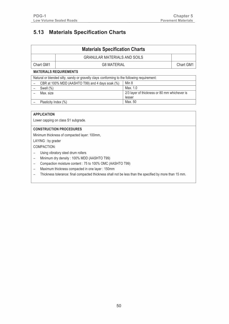
PDG-1 Low Volume Sealed Roads
Chapter 5 Pavement Materials
50
5.13 Materials Specification Charts
Materials Specification Charts GRANULAR MATERIALS AND SOILS
Chart GM1 G8 MATERIAL Chart GM1 MATERIALS REQUIREMENTS Natural or blended silty, sandy or gravelly clays conforming to the following requirement: − CBR at 100% MDD (AASHTO T99) and 4 days soak (%) Min 8 − Swell (%) Max. 1.0 − Max. size 2/3 layer of thickness or 80 mm whichever is
lesser − Plasticity Index (%) Max. 50
APPLICATION Lower capping on class S1 subgrade.
CONSTRUCTION PROCEDURES Minimum thickness of compacted layer: 100mm, LAYING : by grader COMPACTION: − Using vibratory steel drum rollers − Minimum dry density : 100% MDD (AASHTO T99) − Compaction moisture content : 75 to 100% OMC (AASHTO T99) − Maximum thickness compacted in one layer : 150mm − Thickness tolerance: final compacted thickness shall not be less than the specified by more than 15 mm.

PDG-1 Low Volume Sealed Roads
Chapter 5 Pavement Materials
51
Materials Specification Charts
GRANULAR MATERIALS AND SOILS
Chart GM2 G10 MATERIAL Chart GM2 MATERIALS REQUIREMENTS Natural or blended silty/sandy/gravelly clays, silty/clayey sands, sands, or gravels conforming to the following requirement: − CBR at 100% MDD (AASHTO T99) and 4 days soak (%) Min 10 − Swell (%) Max. 1.0 − Max. size 2/3 layer thickness or 80 mm whichever is lesser − Plasticity Index (%) Max. 30
APPLICATION Capping on S1 and S2 subgrades for foundation class F1 and lower capping on S1 and S2 subgrades for higher foundation classes.
CONSTRUCTION PROCEDURES Minimum thickness of compacted layer: 100mm, Tolerance ±15mm. Cross-fall tolerance: +0.25% LAYING: by grader COMPACTION: − Using vibratory steel drum rollers − Minimum dry density : 100% MDD (AASHTO T99) − Compaction moisture content : 75 to 100% OMC (AASHTO T99) − Maximum thickness compacted in one layer : 150mm − Thickness tolerance: final compacted thickness shall not be less than the specified by more than 15 mm.
�
�

PDG-1 Low Volume Sealed Roads
Chapter 5 Pavement Materials
52
Materials Specification Charts
GRANULAR MATERIALS AND SOILS
Chart GM3 G15 MATERIAL Chart GM3
MATERIALS REQUIREMENTS
Natural or blended silty and clayey sands, sands, or gravels conforming to the following requirement: Gravels: − Max. size (mm) 10 – 50 − Passing 0.075 mm sieve (%) Max 40 Sands, silty and clayey sands − Max. size (mm) 0.5 – 10 − Passing 0.075 mm sieve (%) Max 50 All materials: − CBR at 95% MDD (AASHTO T180) and 4 days soak (%) Min 15 − Swell (%) Max. 1.0 − Plasticity Index (%) Max. 30 − Plasticity Modulus Max. 2500 − Organic matter (%) Max 2
APPLICATION Capping on classes S2, and S3 subgrades for classes F1 and F2 foundations and lower capping on classes S2 and S3 subgrades for higher foundation classes.
CONSTRUCTION PROCEDURES Minimum thickness of compacted layer: 100mm, Tolerance ±15mm. Cross-fall tolerance: +0.25% LAYING : by grader COMPACTION: − Using vibratory steel drum rollers − Minimum dry density : 95% MDD (AASHTO T180) − Compaction moisture content : 75 to 100% OMC (AASHTO T180) − Maximum thickness compacted in one layer : 200mm − Thickness tolerance: final compacted thickness shall not be less than the specified by more than 15 mm.
�

PDG-1 Low Volume Sealed Roads
Chapter 5 Pavement Materials
53
Materials Specification Charts
GRANULAR MATERIALS AND SOILS
Chart GM4 G20 MATERIAL Chart GM4
MATERIALS REQUIREMENTS
Natural gravel or mixtures of natural gravel and sand or up to 30% of natural stone, crushed stone, scarified pavement material or milled bituminous pavement material conforming to the following requirement: Bearing strength & plasticity properties Grading After Compaction for
Gravel Wearing Course − CBR at 95% MDD (AASHTO
T180) and 4 days soak (%) Min 20 Sieve
(mm) % by weight passing Class 1 Class 2
− Swell (%) Max. 1.0 37.5 - 100 − Plasticity Index (%) Wet areas 5 – 20 28 100 95 – 100
Dry areas 5 – 25 20 95 – 100 85 – 100 − Plasticity modulus 200 – 1,200 14 80 – 100 65 – 100
10 65 – 100 55 – 100 5 45 – 85 35 – 92 2 30 – 68 23 – 77 1 25 – 56 18 – 62 0.425 18 – 44 14 – 50 0.075 12 – 32 10 – 40
CAPPING MATERIAL − Maximum size 2/3 layer thickness or 80mm
whichever is the lesser
− Uniformity coefficient Min. 5 APPLICATION Capping on S2 and S3 subgrades for foundation classes F1 and F2 and lower capping on S1, S2 and S3 subgrades for higher foundations. Also used as Gravel Wearing Course (GWC) material.
CONSTRUCTION PROCEDURES Minimum thickness of compacted layer: 100mm, Tolerance ±15mm. Cross-fall tolerance: +0.25% LAYING : by grader COMPACTION: − Using vibratory steel drum rollers − Minimum dry density : 95% MDD (AASHTO T180) − Compaction moisture content : between 80 and 100% OMC (AASHTO T180) − Maximum thickness compacted in one layer : 200mm − Thickness tolerance: final compacted thickness shall not be less than the specified by more than 15 mm.

PDG-1 Low Volume Sealed Roads
Chapter 5 Pavement Materials
54
Materials Specification Charts
GRANULAR MATERIALS AND SOILS
Chart GM5 G25 MATERIAL Chart GM5
MATERIALS REQUIREMENTS
Natural gravel or mixtures of natural gravel and sand or up to 30% of natural stone, crushed stone, scarified pavement material or milled bituminous pavement material conforming to the following requirement: Natural Gravels: − CBR at 95% MDD (AASHTO T180) and 4 days soak (%) Min 25 − Swell (%) Max. 1.0 − Max. size 2/3 of layer thickness or 80 mm whichever is
lesser − Uniformity Coefficient Min. 5 − Plasticity Index (%) Wet areas Max 15
Dry areas Max 20 − Plasticity modulus Max 250 Clayey and Silty Sands: − CBR at 95% MDD (AASHTO T180) and 4 days soak (%) Min 25 − Swell (%) Max. 1.0 − Passing 2 mm sieve (%) Max. 95 − Passing 0.075 mm sieve (%) Min 10 – Max 30 − Uniformity Coefficient Min. 5 − Plasticity Index (%) Wet areas Min 5 – Max 15
Dry areas Min 5 – Max 20 − Plasticity modulus Max 250 APPLICATION Sub-base material for T5-1 and T5-2 traffic, capping on S2 to S4 subgrades for foundation class F3, and lower capping on S2 to S4 subgrades for higher foundation classes.
CONSTRUCTION PROCEDURES Minimum thickness of compacted layer: 100mm, Tolerance ±15 mm. Cross-fall tolerance: ±0.50% LAYING : by grader COMPACTION: − Using vibratory steel drum rollers − Minimum dry density : 95% MDD (AASHTO T180) − Compaction moisture content : between 80 and 100% OMC (AASHTO T180) − Maximum thickness compacted in one layer : 200mm − Thickness tolerance: final compacted thickness shall not be less than the specified by more than 15 mm.
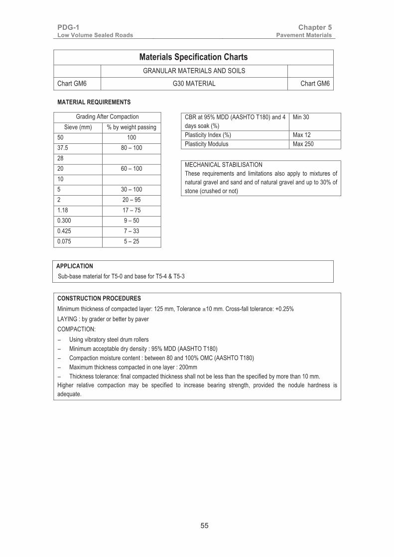
PDG-1 Low Volume Sealed Roads
Chapter 5 Pavement Materials
55
Materials Specification Charts
GRANULAR MATERIALS AND SOILS
Chart GM6 G30 MATERIAL Chart GM6
MATERIAL REQUIREMENTS
APPLICATION Sub-base material for T5-0 and base for T5-4 & T5-3
� �
Grading After Compaction Sieve (mm) % by weight passing
50 100 37.5 80 – 100 28 20 60 – 100 10 5 30 – 100 2 20 – 95 1.18 17 – 75 0.300 9 – 50 0.425 7 – 33 0.075 5 – 25
CBR at 95% MDD (AASHTO T180) and 4 days soak (%)
Min 30
Plasticity Index (%) Max 12 Plasticity Modulus Max 250 MECHANICAL STABILISATION These requirements and limitations also apply to mixtures of natural gravel and sand and of natural gravel and up to 30% of stone (crushed or not)
CONSTRUCTION PROCEDURES Minimum thickness of compacted layer: 125 mm, Tolerance ±10 mm. Cross-fall tolerance: +0.25% LAYING : by grader or better by paver COMPACTION: − Using vibratory steel drum rollers − Minimum acceptable dry density : 95% MDD (AASHTO T180) − Compaction moisture content : between 80 and 100% OMC (AASHTO T180) − Maximum thickness compacted in one layer : 200mm − Thickness tolerance: final compacted thickness shall not be less than the specified by more than 10 mm. Higher relative compaction may be specified to increase bearing strength, provided the nodule hardness is adequate.

PDG-1 Low Volume Sealed Roads
Chapter 5 Pavement Materials
56
Materials Specification Charts
GRANULAR MATERIALS AND SOILS
Chart GM7 G50 MATERIAL Chart GM7
MATERIAL REQUIREMENTS
Grading After Compaction Sieve (mm) % by weight passing
50 100 37.5 90 – 100 28 75 – 95 20 60 – 90 10 40 – 75 5 29 – 65 2 20 – 45 1.18 17 – 40 0.425 12 – 31 0.075 5 – 25
�
CBR at 95% MDD (AASHTO T180) and 4 days soak (%)
Min 50
Los Angeles Abrasion (%) Max. 70 Aggregate Crushing Value (%) Max. 40 Plasticity Index (%) Max 10 Plasticity Modulus Max 250 MECHANICAL STABILISATION These requirements and limitations also apply to mixtures of natural gravel and sand and of natural gravel and up to 30% of stone (crushed or not)
CONSTRUCTION PROCEDURE Minimum thickness of compacted layer: 125 mm, Tolerance ±10 mm. Cross-fall tolerance: +0.25% Laying : by grader or better by paver COMPACTION: − Using vibratory steel drum rollers − Minimum acceptable dry density : 95% MDD (AASHTO T180) − Compaction moisture content : between 80 and 105% OMC (AASHTO T180) − Maximum thickness compacted in one layer : 200mm − Thickness tolerance: final compacted thickness shall not be less than the specified by more than 10 mm. Higher relative compaction may be specified to increase bearing strength, provided the nodule hardness is adequate.
APPLICATION Base for T5-2 & T5-1 traffic.

PDG-1 Low Volume Sealed Roads
Chapter 5 Pavement Materials
57
Materials Specification Charts
GRANULAR MATERIALS AND SOILS
Chart GM8 G80 MATERIAL Chart GM8
MATERIAL REQUIREMENTS
Grading After Compaction Sieve (mm) % by weight passing
50 100 37.5 95 – 100 28 80 – 100 20 60 – 100 10 35 – 100 5 20 – 95 2 12 – 80 1 10 – 65 0.425 7 – 50 0.075 4 – 20 APPLICATION Base for T5-0. In areas with annual rainfall less than 500 mm, if permission has been sought and granted by the Chief Engineer Materials, G60 may be used as an alternative to G80 base for T5-0.
�
CBR at 95% MDD (AASHTO T180) and 4 days soak (%)
Min 80
Los Angeles Abrasion (%) Max. 50 Aggregate Crushing Value (%) Max. 35 Plasticity Index (%) Max 10 Plasticity Modulus (%) Max 250
MECHANICAL STABILISATION These requirements and limitations also apply to mixtures of natural gravel and sand and of natural gravel and up to 30% of stone (crushed or not)
CONSTRUCTION PROCEDURES Minimum thickness of compacted layer: 125 mm, Tolerance ±10 mm. Cross-fall tolerance: +0.25% Laying : by grader or better by paver COMPACTION: − Using vibratory steel drum rollers − Minimum acceptable dry density : 95% MDD (AASHTO T180) − Compaction moisture content : between 80 and 105% OMC (AASHTO T180) − Maximum thickness compacted in one layer : 200mm − Thickness tolerance: final compacted thickness shall not be less than the specified by more than 10 mm. Higher relative compaction may be specified to increase bearing strength, provided the nodule hardness is adequate.
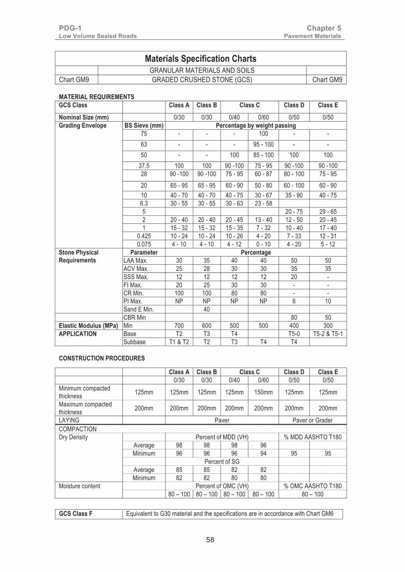
PDG-1 Low Volume Sealed Roads
Chapter 5 Pavement Materials
58
Materials Specification Charts GRANULAR MATERIALS AND SOILS
Chart GM9 GRADED CRUSHED STONE (GCS) Chart GM9 MATERIAL REQUIREMENTS GCS Class Class A Class B Class C Class D Class E
Nominal Size (mm) 0/30 0/30 0/40 0/60 0/50 0/50 Grading Envelope BS Sieve (mm) Percentage by weight passing
75 - - - 100 - - 63 - - - 95 - 100 - - 50 - - 100 85 - 100 100 100
37.5 100 100 90 -100 75 - 95 90 -100 90 -100 28 90 -100 90 -100 75 - 95 60 - 87 80 - 100 75 - 95 20 65 - 95 65 - 95 60 - 90 50 - 80 60 - 100 60 - 90 10 40 - 70 40 - 70 40 - 75 30 - 67 35 - 90 40 - 75 6.3 30 - 55 30 - 55 30 - 63 23 - 58 5 20 - 75 29 - 65 2 20 - 40 20 - 40 20 - 45 13 - 40 12 - 50 20 - 45 1 15 - 32 15 - 32 15 - 35 7 - 32 10 - 40 17 - 40
0.425 10 - 24 10 - 24 10 - 26 4 - 20 7 - 33 12 - 31 0.075 4 - 10 4 - 10 4 - 12 0 - 10 4 - 20 5 - 12
Stone Physical Requirements
Parameter Percentage LAA Max. 30 35 40 40 50 50 ACV Max. 25 28 30 30 35 35 SSS Max. 12 12 12 12 20 - FI Max. 20 25 30 30 - - CR Min. 100 100 80 80 - - PI Max. NP NP NP NP 6 10 Sand E Min. 40
CBR Min 80 50 Elastic Modulus (MPa) Min 700 600 500 500 400 300 APPLICATION Base T2 T3 T4 T5-0 T5-2 & T5-1
Subbase T1 & T2 T2 T3 T4 T4
CONSTRUCTION PROCEDURES
Class A Class B Class C Class D Class E 0/30 0/30 0/40 0/60 0/50 0/50 Minimum compacted thickness 125mm 125mm 125mm 125mm 150mm 125mm 125mm
Maximum compacted thickness 200mm 200mm 200mm 200mm 200mm 200mm 200mm
LAYING Paver Paver or Grader COMPACTION Dry Density Percent of MDD (VH) % MDD AASHTO T180
Average 98 98 98 96 Minimum 96 96 96 94 95 95
Percent of SG Average 85 85 82 82 Minimum 82 82 80 80
Moisture content Percent of OMC (VH) % OMC AASHTO T180 80 – 100 80 – 100 80 – 100 80 – 100 80 – 100
�GCS Class F Equivalent to G30 material and the specifications are in accordance with Chart GM6

PDG-1 Low Volume Sealed Roads
Chapter 5 Pavement Materials
59
�
Materials Specification Charts
HYDRAULICALLY IMPROVED GRANULAR MATERIAL (HIG)
Chart HIG-1 HIG OF MINIMUM CBR 50% (HIG 50) Chart HIG-1 MATERIALS REQUIREMENTS
Material Before treatment Cement/HRB Experience has shown that materials which comply with the following requirements are generally suitable for improvement.
Portland cement (CEM I – 42.5 MPa) complying to KS EAS 18-1 or HRB complying with BS EN 13282.
− Material classification − Grading for natural gravels:
Maximum size Passing 0.075 mm sieve
− Grading for sands, silty sands and clayey sands:
Maximum size Passing 0.075 mm sieve
− Plasticity Index: − Plasticity Modulus: − Organic Matter: − Extra requirements for lime treatment:
Passing 0.425 mm sieve Plasticity Index
Min G15 10 – 15 mm Max. 40% 0.5 – 10 mm Max. 50% Max. 25% Max. 2,500 Max. 2% Min. 15% Min. 10
Amounts required: Plastic gravels Sands and clayey sands
2 – 4% 2 – 3%
Lime Hydrated calcium lime (See standard
specification)
Amounts usually required:
1 – 4%
Treated Material
HIG50: CBR of Laboratory mix at 95% MDD (modified AASHTO) and 7 days cure + 7 days soak: 50%, PI min 5% - max 12%. PM max 250.
APPLICATION Subbase for T5-4 and T5-3 CONSTRUCTION PROCEDURES Minimum thickness of compacted layer: 100mm, Tolerance ±15 mm. Cross-fall tolerance ±0.50% Laying : by grader Mixing : in place (pulvimixer or travel plant) COMPACTION: − Using vibratory steel drum rollers − Minimum dry density : 95% MDD (AASHTO T180) − Compaction moisture content : between OMC-2 and OMC (AASHTO T180) − Maximum thickness compacted in one layer : 200mm − Time allowed to complete compaction and finishing : 2hrs (cement), 4hrs (lime) − Thickness tolerance: final compacted thickness shall not be less than the specified by more than 15 mm. PROTECTION AND CURING: − Time allowed to place protection : 8 hours (lime), 4 hours (cement) − No traffic permitted for first 7 days
�

PDG-1 Low Volume Sealed Roads
Chapter 5 Pavement Materials
60
Materials Specification Charts
HYDRAULICALLY IMPROVED GRANULAR MATERIAL (HIG)
Chart HIG-2 HIG OF MINIMUM CBR 60% (HIG 60) Chart HIG-2 MATERIALS REQUIREMENTS
Material Before treatment Cement/HRB
Experience has shown that materials which comply with the following requirements are generally suitable for improvement.
Portland cement (CEM I – 42.5 MPa) complying to KS EAS 18-1 or HRB complying to BS EN 13282.
− Material classification − Grading for natural gravels:
Maximum size Passing 0.075 mm sieve
− Grading for sands, silty sands and clayey sands:
Maximum size Passing 0.075 mm sieve
− Plasticity Index: − Plasticity Modulus: − Organic Matter: − Extra requirements for lime treatment:
Passing 0.425 mm sieve Plasticity Index
G20 10 – 15 mm Max. 40% 0.5 – 10 mm Max. 50% Max. 25% Max. 2,500 Max. 2% Min. 15% Min. 10
Amounts usually required: Plastic gravels Sands and clayey sands
2 – 4% 2 – 4%
Lime Hydrated calcium lime (See standard
specification)
Amounts usually required: 2 – 4%
Treated Material
HIG60: CBR of Laboratory mix at 95% MDD (modified AASHTO) and 7 days cure + 7 days soak: 60%, PI min 5% - max 12%. PM max 250.
APPLICATION
Subbase for T5-0 and Base for T5-4 and T5-3
CONSTRUCTION PROCEDURES
Minimum thickness of compacted layer: 100mm, Tolerance ±15 mm. Cross-fall tolerance ±0.50%
LAYING : by grader
MIXING : in place (pulvimixer or travel plant)
COMPACTION: − Using vibratory steel drum rollers − Minimum dry density : 95% MDD (AASHTO T180) − Compaction moisture content : between OMC-2 and OMC (AASHTO T180) − Maximum thickness compacted in one layer : 200mm − Time allowed to complete compaction and finishing : 2hrs (cement), 4hrs (lime) − Thickness tolerance: final compacted thickness shall not be less than the specified by more than 15 mm.
PROTECTION AND CURING: − Time allowed to place protection : 8 hours (lime), 4 hours (cement) − No traffic permitted for first 7 days �
� �
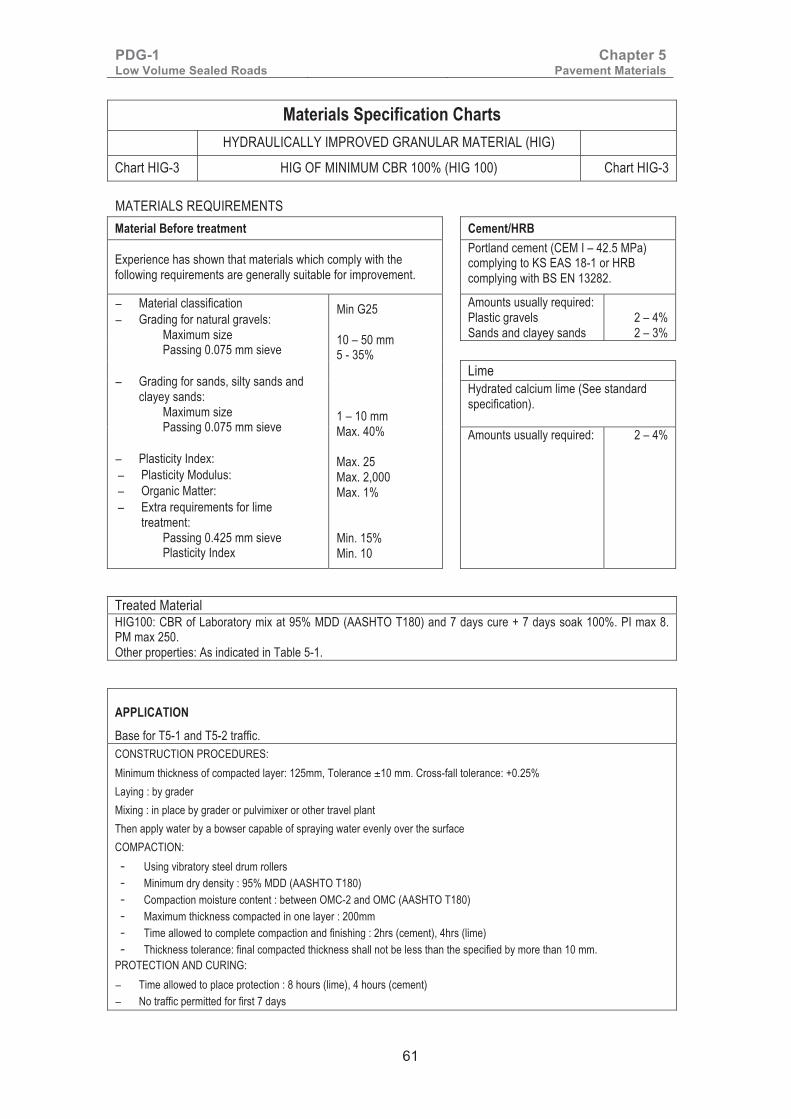
PDG-1 Low Volume Sealed Roads
Chapter 5 Pavement Materials
61
Materials Specification Charts
HYDRAULICALLY IMPROVED GRANULAR MATERIAL (HIG)
Chart HIG-3 HIG OF MINIMUM CBR 100% (HIG 100) Chart HIG-3
MATERIALS REQUIREMENTS Material Before treatment Cement/HRB
Experience has shown that materials which comply with the following requirements are generally suitable for improvement.
Portland cement (CEM I – 42.5 MPa) complying to KS EAS 18-1 or HRB complying with BS EN 13282.
− Material classification − Grading for natural gravels:
Maximum size Passing 0.075 mm sieve
− Grading for sands, silty sands and clayey sands:
Maximum size Passing 0.075 mm sieve
− Plasticity Index: − Plasticity Modulus: − Organic Matter: − Extra requirements for lime
treatment: Passing 0.425 mm sieve Plasticity Index
Min G25 10 – 50 mm 5 - 35% 1 – 10 mm Max. 40% Max. 25 Max. 2,000 Max. 1% Min. 15% Min. 10
Amounts usually required: Plastic gravels Sands and clayey sands
2 – 4% 2 – 3%
Lime Hydrated calcium lime (See standard
specification). Amounts usually required: 2 – 4%
Treated Material HIG100: CBR of Laboratory mix at 95% MDD (AASHTO T180) and 7 days cure + 7 days soak 100%. PI max 8. PM max 250. Other properties: As indicated in Table 5-1.
APPLICATION
Base for T5-1 and T5-2 traffic. CONSTRUCTION PROCEDURES: Minimum thickness of compacted layer: 125mm, Tolerance ±10 mm. Cross-fall tolerance: +0.25% Laying : by grader Mixing : in place by grader or pulvimixer or other travel plant Then apply water by a bowser capable of spraying water evenly over the surface COMPACTION: - Using vibratory steel drum rollers - Minimum dry density : 95% MDD (AASHTO T180) - Compaction moisture content : between OMC-2 and OMC (AASHTO T180) - Maximum thickness compacted in one layer : 200mm - Time allowed to complete compaction and finishing : 2hrs (cement), 4hrs (lime) - Thickness tolerance: final compacted thickness shall not be less than the specified by more than 10 mm.
PROTECTION AND CURING: − Time allowed to place protection : 8 hours (lime), 4 hours (cement) − No traffic permitted for first 7 days

PDG-1 Low Volume Sealed Roads
Chapter 5 Pavement Materials
62
�
Materials Specification Charts
HYDRAULICALLY IMPROVED GRANULAR MATERIAL (HIG)
Chart HIG-4 HIG OF MINIMUM CBR 160% (HIG 160) Chart HIG-4
MATERIALS REQUIREMENTS
Material Before treatment Cement/HRB
Experience has shown that materials which comply with the following requirements are generally suitable for improvement.
Portland cement (CEM I – 42.5 MPa) complying to KS EAS 18-1 or HRB complying with BS EN 13282.
− Material classification − Grading for natural gravels:
Maximum size Passing 0.075 mm sieve
− Grading for sands, silty sands and clayey sands:
Maximum size Passing 0.075 mm sieve
− Plasticity Index: − Plasticity Modulus: − Organic Matter: − Extra requirements for lime treatment:
Passing 0.425 mm sieve Plasticity Index
Min G30 10 – 50 mm 5 - 35% 1 – 10 mm Max. 40% Max. 15 Max. 2,000 Max. 1% Min. 15% Min. 10
Amounts required: Plastic gravels Sands and clayey sands
2 – 4% 2 – 4%
Lime Hydrated calcium lime (See standard
specification)
Amounts usually required: 2– 4%
Treated Material HIG160: CBR of Laboratory mix at 95% MDD (modified AASHTO) and 7 days cure + 7 days soak 160%. PI max 6. PM max 250.
APPLICATION
Base for T5-0, T4, and T3 and Subbase for T1 and T2 traffic. CONSTRUCTION PROCEDURES: Minimum thickness of compacted layer: 125mm, Tolerance ±10 mm. Cross-fall tolerance: +0.25% Laying : by grader Mixing : in place by grader or pulvimixer or other travel plant Then apply water by a bowser capable of spraying water evenly over the surface COMPACTION: - Using vibratory steel drum rollers - Minimum dry density : 95% MDD (AASHTO T180) - Compaction moisture content : between OMC-2 and OMC (AASHTO T180) - Maximum thickness compacted in one layer : 200mm - Time allowed to complete compaction and finishing : 2hrs (cement), 4hrs (lime) - Thickness tolerance: final compacted thickness shall not be less than the specified by more than 10 mm.
PROTECTION AND CURING: − Time allowed to place protection : 8 hours (lime), 4 hours (cement) − No traffic permitted for first 7 days � �

PDG-1 Low Volume Sealed Roads
Chapter 5 Pavement Materials
63
Materials Specification Charts
BITUMEN STABILISED MATERIALS (BSM)
Chart BESM 3 BITUMEN EMULSION STABILISED MATERIAL – BESM 3 Chart BESM 3 MATERIALS REQUIREMENTS Material Before treatment Bitumen Stabiliser and Active Filler Material Class Min G30 Bitumen Binder: Slow setting A3 and A4 anionic and
K3 cationic emulsions. Grading Envelope Sieve size % Passing 50 100 Lime for Pre-treatment and Active Filler:
Hydrated calcium lime (See standard specification) Amounts usually required: pre-treatment 1 to 2% and maximum of 1% as active filler.
37.5 90 – 100 28 80 – 100
20 60 – 100 Cement for Active Filler: Portland cement (CEM I – 42.5 MPa) complying to KS EAS 18-1 or HRB complying with BS EN 13282.
Amounts required: Max 1%
10 35 – 90 5 20 – 75 2 12 – 50 1 10 – 40
0.425 7 – 33 0.075 4 – 20 Recommended Residual Binder Content: CBR after 4 day soak Min 30% Material Residual bitumen (%) Plasticity Index 7 – 12% Reclaimed asphalt pavement 1.75 – 2.50 Organic Mater Max 1% Graded Crushed Rock 2.25 – 3.00 Grading Modulus 1.2 – 2.7 Gravels of CBR ≥ 30% 2.5 – 3.25 Gravels/sands of CBR ≥ 20% 2.5 – 4.0 Treated Material: The mix shall comply with the following specifications: Property Specimen curing regime & moisture conditions Specification ITS dry (kPa) 100 mm diameter Marshall specimen cured for 72 hours at 400C 125 - 225 ITS wet (kPa) 100 mm diameter Marshall specimen cured for 72 hours at 400C
and soaked for 24 hours 50 - 100
UCS soaked (kPa) UCS specimen cured for 72 hours at 400C and soaked for 4 days Min 500 CBR soaked (%) CBR specimen cured for 72 hours at 400C and soaked for 4 days Min 50% TSR Tensile Strength Ratio:(ITSwet/ ITSdry)×100% Min 50% APPLICATION: Base for T5-2, T5-1 and T5-0 traffic.
CONSTRUCTION PROCEDURES: Use bitumen emulsion A4-60%. Dilute with suitable water (40% of bitumen content of emulsion). Minimum permissible residual bitumen content is 2.0 %. Minimum thickness of compacted layer: 100mm, Tolerance ±10 mm. Crossfall tolerance: +0.25% Mixing: in place by travel plant, pulvimixer, disc harrow or grader (least preferred) and stationary batching in a plant or labour based using hand tools i.e. pans. Laying: by grader, paver or labour. Laying should not be done in wet weather conditions. COMPACTION: − Using vibratory steel drum rollers − Minimum dry density : 95% MDD (Vibratory hammer) − Maximum thickness compacted in one layer : 200mm − Thickness tolerance: final compacted thickness shall not be less than the specified by more than 10 mm. PROTECTION AND CURING: − Not applicable, allows immediate trafficking
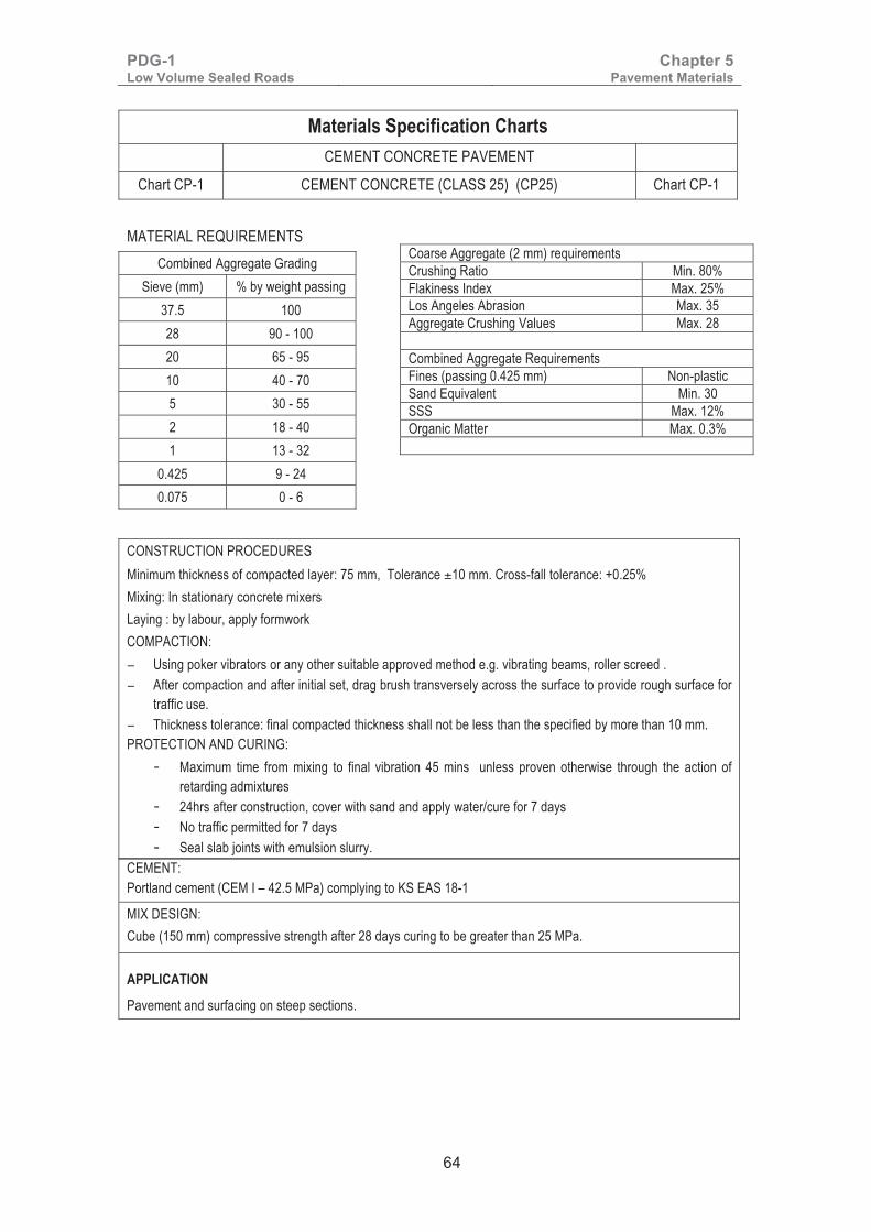
PDG-1 Low Volume Sealed Roads
Chapter 5 Pavement Materials
64
Materials Specification Charts
CEMENT CONCRETE PAVEMENT
Chart CP-1 CEMENT CONCRETE (CLASS 25) (CP25) Chart CP-1
MATERIAL REQUIREMENTS
Combined Aggregate Grading Sieve (mm) % by weight passing
37.5 100 28 90 - 100 20 65 - 95 10 40 - 70 5 30 - 55 2 18 - 40 1 13 - 32
0.425 9 - 24 0.075 0 - 6
Coarse Aggregate (2 mm) requirements Crushing Ratio Min. 80% Flakiness Index Max. 25% Los Angeles Abrasion Max. 35 Aggregate Crushing Values Max. 28 Combined Aggregate Requirements Fines (passing 0.425 mm) Non-plastic Sand Equivalent Min. 30 SSS Max. 12% Organic Matter Max. 0.3%
CONSTRUCTION PROCEDURES Minimum thickness of compacted layer: 75 mm, Tolerance ±10 mm. Cross-fall tolerance: +0.25% Mixing: In stationary concrete mixers Laying : by labour, apply formwork COMPACTION: − Using poker vibrators or any other suitable approved method e.g. vibrating beams, roller screed . − After compaction and after initial set, drag brush transversely across the surface to provide rough surface for
traffic use. − Thickness tolerance: final compacted thickness shall not be less than the specified by more than 10 mm. PROTECTION AND CURING:
- Maximum time from mixing to final vibration 45 mins unless proven otherwise through the action of retarding admixtures
- 24hrs after construction, cover with sand and apply water/cure for 7 days - No traffic permitted for 7 days - Seal slab joints with emulsion slurry.
CEMENT: Portland cement (CEM I – 42.5 MPa) complying to KS EAS 18-1
MIX DESIGN: Cube (150 mm) compressive strength after 28 days curing to be greater than 25 MPa.
APPLICATION
Pavement and surfacing on steep sections.

PDG-1 Low Volume Sealed Roads
Chapter 5 Pavement Materials
65
Materials Specification Charts
HAND PACKED STONE
Chart B1G HAND PACKED STONE BASE Chart B1G
MATERIAL REQUIREMENTS
PARENT ROCK CBR at 95% MDD (AASHTO T180) and 4 days soak Min 80% Los Angeles Abrasion Max 50% Aggregate Crushing Value Max 35% Plasticity Index Max 15%
STONE DIMENSIONS
Dimension 150mm Stone 200mm Stone
Length 150 200
Width 100 - 150 100 - 200
Breadth 100 - 150 100 - 200 FILLER (0/10mm Aggregates) Sieve Size % Passing 10 100 6.3 90-100 4 75-95 2 50-70 1 33-50 0.425 20-33 0.300 16-28 0.150 10-20 0.075 6-12 TRAFFIC LIMITATIONS:
Subbase and Base for T5-2 to T3 traffic.
CONSTRUCTION PROCEDURES A Sub-base of minimum G30 must be provided; constructed as other sub-bases Pack stones tightly, wedge stones with smaller stone chips using hammers and steel rods Provide appropriate surfacing

PDG-1 Low Volume Sealed Roads
Chapter 5 Pavement Materials
66
Materials Specification Charts
PAVING BLOCKS
Chart PB1 INTERLOCKING COBBLESTONE SURFACING Chart PB1 MATERIAL REQUIREMENTS COBBLESTONE, KERBSTONES AND INTERSECTION STONES Compressive strength at 28 days cure Min 25 MPa Water absorption Max 10% Los Angeles Abrasion Max 50% Specific gravity (g/cc) 2 – 2.8 Cobble Stone Dimension:
Category Type Length (mm) Breadth (mm) Depth (mm) Tolerance
Cubical Shape 10 100 100 100
Faces raw chiselled with max 5 mm
roughness difference, crack-free
and clean
11/13 110 – 130 110 – 130 130 14/17 140 - 170 140 - 170 150
Stretcher Shape
13 ≥ 130 110 110 16 ≥ 160 110 – 130 150 20 ≥ 200 140 – 160 150
Kerbstone and Intersection Stone Dimension: • Kerbstones shall be rectangular blocks of 400mm (length) x 100mm (width) x 200mm (depth) chiselled or
machine. • The intersection stones shall comprise of the first two rows of cobblestone as specified above laid adjacent
to the kerbstone. BEDDING AND JOINT FILLER MATERIAL Material for the laying course and joint filler shall be naturally occurring clean sand or crushed rock fines, free from clay, lumps or other deleterious material with a grading curve falling within the following envelope: Nominal Sieve Size (mm) Percentage by Mass Passing (%)
10.00 100 5.00 90 – 100 2.36 75 – 100 1.18 55 – 90
600µm 34 – 70 300 µm 8 – 35 150 µm 0 – 10 75µm 0 – 3
APPLICATION Base/Surfacing for low speed T5-2, T5-1 and T5-0 traffic. CONSTRUCTION PROCEDURES Sub-Base/Foundation material shall be at least G30 in accordance with Chart GM6 Kerbs shall be set and embedded in concrete class 15/20 to line and levels as per design and drawings. After installation of Kerbs, the sub-base shall be primed with MC 70 or MC 30 cutback bitumen depending on the permeability of the underlying material. Allow prime to cure/dry Apply bedding sand on the sub-base to a thickness of 25 – 50 mm Pack stones tightly, brush sand into spaces between stones, compact with a light non-vibratory roller or plate compactor Brush more sand in and leave loose sand on surfacing for 2 weeks after opening to traffic then brush off

PDG-1 Low Volume Sealed Roads
Chapter 5 Pavement Materials
67
Materials Specification Charts PAVING BLOCKS
Chart PB2 INTERLOCKING CONCRETE PAVING BLOCK SURFACING Chart PB2
MATERIAL REQUIREMENTS
PRECAST CONCRETE BLOCKS (PCB) PCB shall be manufactured in compliance to KS 827 and are graded in the following strength categories:
Grade Nominal Thickness (mm)
Compressive Strength (N/mm2)
Traffic Application
Heavy Duty (H) 80 49 Main roads & heavy industrial applications
60 49
Medium Duty (M) 60 35 Estate roads and parking areas
Light Duty (L) 50 25 Domestic driveways, parking areas & sidewalks
Categories of Paving Blocks by Dimension: Grading of Aggregates for Concrete Blocks:
Category Length (mm) Width (mm) Thickness Sieve Size (mm) % Passing
Type R 200 100 As above 14.00 100
Type S Any shape fitting within a 295mm square coordinating space, having a work size of not less than 80mm
10.00 85 – 100
6.30 0 – 55
5.00 0 – 10 Bedding & Joint Filler Material: Material for the laying course and joint filler shall be naturally occurring clean sand or crushed rock fines, free from clay, lumps or other deleterious material with a grading curve falling within the following envelope: Nominal Sieve Size (mm) Percentage by Mass Passing (%)
10.00 100 5.00 90 – 100 2.36 75 – 100 1.18 55 – 90
600µm 34 – 70 300 µm 8 – 35 150 µm 0 – 10 75µm 0 – 3
APPLICATION Base/Surfacing for low speed traffic as indicated above. CONSTRUCTION PROCEDURES Sub-Base/Foundation material shall be at least G30 in accordance with Chart GM6 Kerbs shall be set and embedded in concrete class 15/20 to line and levels as per design and drawings. After installation of Kerbs, the sub-base shall be primed with MC 70 or MC 30 cutback bitumen depending on the permeability of the underlying material. Allow prime to cure/dry Apply bedding sand on the sub-base to a thickness of 25 – 50 mm Pack stones tightly, brush sand into spaces between stones, compact with a light non-vibratory roller or plate compactor. Brush more sand in and leave loose sand on surfacing for 2 weeks after opening to traffic then brush off

PDG-1 Low Volume Sealed Roads
Chapter 5 Pavement Materials
68
Materials Specification Charts SURFACING MATERIALS Chart S1 SURFACE DRESSING Chart S1
MATERIALS REQUIREMENTS
Bituminous Binder Cationic emulsion K1-70 and 80/100 penetration grade bitumen Chippings Grading Chippings Requirements Sieve (mm)
Nominal Size (mm) Chipping class 1 2 3 4 14/20 10/14 6/10 3/6 LAA Max. 20 25 30 35
28 100 - - - ACV Max. 16 20 23 26 20 85 - 100 100 - - SSS Max. 12 12 12 12 14 0 – 30 85 – 100 100 - FI Max. 20 20 25 25 10 0 – 7 0 – 30 85 – 100 100 Angularity (all classes):
Minimum size of stone to be at least 4 times maximum size of chippings. Cleanliness (all classes): Passing 0.075 mm: Max. 1% Free of deleterious matter.
6.3 - 0 – 7 0 – 30 85 - 100 5 - - 0 – 10 - 3 - - - 0 – 30 2 0 – 2 0 – 2 0 – 2 0 – 10 0.5 - - - 0 - 2
Crushed Rock Sand (wholly derived from crushed stone)
Sieve size (mm) % passing by weight 6.30 100
0.300 0 – 15 0.150 0 - 2
TRAFFIC LIMITATION Total traffic on 2 lanes (veh./day) in year of application of chippings >6,000 2,000 – 6,000 500 – 2,000 <500
Chippings class required 1 2 3 4 CONSTRUCTION PROCEDURES Use of K1-70 bitumen emulsion should only be considered if other options are not possible. It requires very high spray rates to attain the specified residual binder content which makes it flow off the surface during spraying on steep and elevated sections. Economically, it has high ex-factory and transport cost components and therefore only viable if produced on site. 80/100 PG bitumen may be blended with up to 5% kerosene depending on road surface temperature to enable uniform spray rate. SPRAYING: − by bitumen distributor − Spraying temperatures: K1 – 70 : 75 – 85 oC; and 80/100 PG : 160 - 170 oC − The rate of application shall not vary by more than ±10%
SPREADING THE CHIPPINGS: − By mechanical spreader − Time allowed (after spraying) to spread chippings : 1 minute − The rate of application shall not vary by more than ±10%
ROLLING: − Preferably by pneumatic tyred rollers (minimum 1 tonne per wheel) − Steel wheeled rollers of less than 8 tonnes accepted − Time allowed (after spraying) to start rolling : 2 minutes
TRAFFIC CONTROL: − Speed must be restricted to 30 km/hr until chippings are held.

PDG-1 Low Volume Sealed Roads
Chapter 5 Pavement Materials
69
Materials Specification Charts
SURFACING MATERIALS
Chart S2 EMULSION SLURRY SEAL Chart S2
MATERIALS REQUIREMENTS Anionic emulsion A4-60 (slow-setting slurry), or Cationic emulsion K1-60 (quick-setting slurry), K3-65 (slow-setting slurry)
Aggregate Grading Aggregate
Sieve Size (mm)
% by weight passing Shall be free of organic and other
deleterious matter
Type I (Fine) Type II (Normal)
Type III (Coarse) Sand Equivalent : Min. 40
10 - - 100 Percentage of crusher dust :
6.3 - 100 80 – 95 Slurry Class A Min. 50%
5 - 90 – 100 70 – 90 Slurry Class B Min. 25%
2 100 60 – 87 40 – 65 1 60 – 85 40 – 67 25 – 45 Mineral Filler 0.425 30 – 48 22 – 38 15 – 28 Cement complying to KS EAS 18-1, HRB
complying to BS EN 13282, Hydrated Lime or other non-plastic mineral matter 0.300 25 – 42 18 – 30 12 – 25
0.150 15 – 30 10 – 20 7 – 18 0.075 10 - 20 5 - 15 5 - 15 Usual amount : 1% (by weight)
Mixture: Emulsion: 15 – 25% (by weight of dry aggregate)
Water : 10 – 25% (by weight of dry aggregate)
Rate of application : 130 – 250 m2/m3 (4 – 8 litre/m2)
CONSTRUCTION PROCEDURES
MIXING: by concrete mixer or preferably slurry machine LAYING: by slurry machine CURING: no traffic until cured to a firm condition (no pick-up by tyres) ROLLING: if required, by pneumatic tyred roller NOTE: The wet track abrasion test gives some guidance for initial emulsion content, and application rate selection. However, for all roads carrying substantial traffic it is considered necessary to observe the performance of trial sections under traffic before selecting a job mix and application rate. � �

PDG-1 Low Volume Sealed Roads
Chapter 5 Pavement Materials
70
Materials Specification Charts
SURFACING MATERIALS
Chart S3 COLD MIX ASPHALT SEAL Chart S3
MATERIALS REQUIREMENTS
Cationic emulsion K3-65 (slow setting) and suitable aggregates
Aggregate Grading Aggregate Requirements
Sieve Size (mm)
% by weight passing LAA Max. 40 0/10 0/14 ACV Max. 30
20 100 100 SSS Max. 12 14 100 90 - 100 FI Max. 25 10 90 - 100 70 - 95 Sand Equivalent Min 40 6.3 62 - 90 55 - 85 Binder Content 4 50 - 80 46 - 75 0/10 Aggregates 6 – 7.5% 2 35 - 65 35 - 60 0/14 Aggregates 5.5 – 7.0% 1 25 - 50 25 - 45 Properties of Compacted Mix 0.425 14 - 33 14 - 32 Modified Marshall Stability
at 50 blows, 24 hr oven cure at 40oC and 1 hr soak (N)
Min 3000
0.300 11 - 27 11 - 27
0.150 6 - 17 6 - 17 Voids in Total Mix (%) 3 – 8 0.075 3 - 8 3 - 8 Flow (mm) 2 – 5
Mineral Filler Stability loss after immersion (%)
Max 50
Cement , Lime or other non-plastic materials Aggregate Coating (%) Min 50
APPLICATION
Suitable for traffic classes T5-2, T5-1 & T5-0
CONSTRUCTION PROCEDURES MIXING: in a stationary plant, concrete mixer or in pans using labour: LAYING: by paver and labour using guide rails. CURING: no traffic until cured to a firm condition (no pick-up by tyres). Quarry dust or sand may be applied to facilitate immediate passage of traffic. ROLLING: preferably a combination of pneumatic tyred roller and steel drum roller maximum 8 tonne
�
�
� �

PDG-1 Low Volume Sealed Roads
Chapter 5 Pavement Materials
71
Materials Specification Charts
SURFACING MATERIALS
Chart S4 OTTA SEAL Chart S4 MATERIALS REQUIREMENTS Bituminous Binder MC 3000 and 150/200 Pen. Grade Bitumen
Aggregate Grading Aggregate Requirements
Sieve (mm) (% passing by weight) Test Designation vpd at construction <100 >100
20 100 10% FACT (Dry) 90 kN 110 kN 14 65 – 100 10 45 – 95 Wet/Dry Strength Ratio 0.60 0.75 6.3 25 – 80 LAA Max 40% 4 15 – 65 ACV Max 30% 2 10 – 50 PI Max 10% 1 5 – 40 FI Max 30% 0.425 3 – 30 0.075 0 – 10 TRAFFIC LIMITATIONS Total traffic on 2 lanes single carriageway in both directions (veh./day) in year of application of aggregates
<100 100 – 1000 >1000
Bitumen Binder 150/200 Pen 150/200 Pen MC 3000 CONSTRUCTION PROCEDURES SPRAYING: − by bitumen distributor − Spraying temperatures: MC 3000: 135 – 155 oC; 150/200 Pen. Grade: 165 – 180 oC; − The rate of application shall not vary by more than ±10%
SPREADING THE CHIPPINGS: − By mechanical spreader − Time allowed (after spraying) to spread chippings : 5 minutes − The rate of application shall not vary by more than ±10%
ROLLING: − Preferably by pneumatic tyred roller (minimum 1 tonne per wheel) at hottest 2 hrs of the day every day for
first 4 days − Steel wheeled roller of less than 8 tonnes accepted for maximum of 4 passes only − Time allowed (after spraying) to start rolling: 2 minutes
TRAFFIC CONTROL: − Speed must be restricted to 30 km/hr until aggregates are held.

PDG-1 Low Volume Sealed Roads
Chapter 5 Pavement Materials
72
Materials Specification Charts
SURFACING MATERIALS
Chart S5 SAND SEAL Chart S5 MATERIALS REQUIREMENTS Bituminous Binder 80/100 Pen Grade Bitumen, MC 3000 & K1-70
Aggregate Grading Aggregate requirements Sieve (mm) Percentage passing Sand Equivalent Max 40
Plasticity Index Non Plastic 6.3 100 Residue binder amount 0.9 to 1.2 litre/m2
5 95 - 100 Sand spread rate 6 to 7 litre/m2
4 90 - 100
2 50 - 95
1 20 - 80
0.6 10 - 50
0.425 3 - 25
0.3 0 - 15
0.15 0 - 8
0.075 0 - 5 TRAFFIC APPLICATION
Total traffic on 2 lanes single carriageway in both directions (veh./day).
Less than 100 vpd sand seal is applied directly on the base layer
100 to 500 vpd Second seal on Surface Dressing or Otta Seal.
CONSTRUCTION PROCEDURES SPRAYING: − by bitumen distributor − Spraying temperatures: MC 800: 110 – 135 oC; MC 3000: 135 – 155 oC; Emulsions at Ambient
Temperature − The rate of application shall not vary by more than ±10%
SPREADING THE CHIPPINGS: − By labour-based methods − Time allowed (after spraying) to spread chippings : 1 minute − The rate of application shall not vary by more than ±10%
ROLLING: − Preferably by pneumatic tyred roller (minimum 1 tonne per wheel) at hottest 2 hrs of the day every day for
first 2 days − Steel wheeled roller of less than 8 tonnes accepted for maximum of 4 passes only − Time allowed (after spraying) to start rolling : 5 minutes
TRAFFIC CONTROL: − Speed must be restricted to 30 km/hr until aggregates are held.

PDG-1 Low Volume Sealed Roads
Chapter 5 Pavement Materials
73
Materials Specification Charts SURFACING MATERIALS Chart S6 ASPHALT CONCRETE (AC II) CONTINUOUSLY GRADED Chart S6 MATERIALS REQUIREMENTS Bituminous Binder: 60/70 or 80/100 penetration grade bitumen at a content rate of 5.5 – 7.5% determined through mix design.
Aggregate Grading Coarse aggregate > 2 mm Sieve (mm)
Nominal Size (mm) Agg. class a b c 0/10 0/14 LAA Max. 30 35 40
28 - - ACV Max. 25 28 30 20 - 100 SSS Max. 12 12 12 14 100 90 - 100 FI Max. 20 25 25 10 90 - 100 70 - 95 Fine Aggregate < 2 mm 6.3 62 - 90 55 - 85 Sand Equivalent Min. 40% 4 50 - 80 46 - 75 SSS Max. 12% 2 35 - 65 35 - 60 Mineral Filler 1 25 - 50 25 - 45 Cement, Lime, Limestone or other mineral matter.
Shall be non-plastic 0.425 14 - 33 14 - 32 0.300 11 - 27 11 - 27 Passing 0.425 mm 100% 0.150 6 - 17 6 - 17 Passing 0.075 mm 75%
0.075 3 - 8 3 - 8 Bulk Density in Toluene 0.5 -0.9 g/ml
AC II Mix Requirements Crushing Raio 60% Marshall Stability 4 – 7 kN Flow Value 2 – 5 mm Voids in total mix 3 – 8 %
APPLICATION
AC II is suitable for T5, T4, and T3. For T5 and T4, coarse aggregate types c, b, and a are all suitable. For T3 coarse aggregate type b and a are both suitable. CONSTRUCTION PROCEDURES MIXING: − In stationary plant, bitumen temperatures : 60/70 PG 130 – 150 oC; 80/100 PG 120 - 140 oC
LAYING: − By mechanical paver at minimum temperatures 130 oC (60/70) and 125 oC (80/100)
COMPACTION: − Minimum density: 96% Laboratory design Marshall density − Minimum temperature at end of compaction: 80 oC (60/70) and 70 oC(80/100) − Steel wheel roller (5-7 kg/mm of roll width) − Pneumatic tyred roller (Min. 2 tonnes per wheel) − Minimum compacted layer thickness: 25 mm.
PDG-1 Low Volume Sealed Roads
Chapter 6 Pavement Design Principles and
Methods
74
Chapter 6: Pavement Design Principles and Methods
6.1 Introduction A road pavement is a durable multi-layered structure built on a foundation of formed natural ground (subgrade), which may be topped with a capping layer, intended to sustain vehicular or pedestrian traffic. Thus the primary purpose of the road pavement is to provide sufficient protection to the subgrade by reducing the stresses to levels that are low enough to prevent subgrade deformation and failure. At the same time the pavement itself should not fail, and is therefore constructed of relatively strong materials.
The key pavement design parameters are the traffic loading, bearing strength of the subgrade, which determines how much protection is required, and the strength of the pavement layers. The elastic modulus controls the load spreading properties of the pavement and therefore determines how thick it needs to be to reduce the stresses on the subgrade to permissible levels.
6.2 Design Criteria The designs were developed through an empirical - mechanistic method. The method involved the determination of thicknesses based on empirical methods and the use of a multi-layer, linear elastic response model to calculate the critical stresses or strains induced under a single standard wheel load (40 kN) that is represented by a circular patch (0.151 m radius) with a uniform vertical stress. The critical stress or strain was then compared with a permissible value to achieve the required design life.
The mechanisms of deterioration that form the basis of the pavement design are:
• Rutting in the subgrade,
• Fatigue cracking at the bottom of the bituminous layers and,
• Horizontal cracking at the bottom of the hydraulically bound (cemented) layers.
The pavements under this guideline are mostly flexible pavements for traffic loading below 1,000,000 ESA and comprise granular, hydraulically modified or bitumen stabilised granular materials, which do not exhibit any tensile strain at the bottom of the layer. The only failure criteria that would be relevant is the compressive stress/strain on top of the subgrade. The objective of the design is therefore to determine the minimum thickness that would reduce the compressive stress/strain on top of the subgrade, induced by a standard wheel load to permissible levels.
In the case of bound materials, the thickness required for each individual layer is determined by a comparison between the tensile strain at the bottom of the layer and the maximum permissible strain, as deduced from the fatigue

PDG-1 Low Volume Sealed Roads
Chapter 6 Pavement Design Principles and
Methods
75
law of the material. In addition, the comprehensive strain on the subgrade is checked, so as not to exceed the permissible value.
6.3 Subgrade Characterisation
6.3.1 Subgrade Failure Criterion It is widely accepted that the compressive strain on the surface of the subgrade is the criterion that governs the total cover required in the case of a flexible pavement. If the compressive strain is excessive, permanent deformation will occur in the subgrade and this will cause deformation at the Pavement surface.�
The relationship between the maximum permissible compressive strain and the cumulative number of standard axles is usually given by an empirical equation called the “subgrade failure criterion”, which relates the vertical strain at subgrade level to pavement rutting performance.
The general relationship is:
N = (A/ε)n
��Where:
ɛ is in micro-strain (i.e. strain/1,000,000) N is the number of cumulative equivalent standard axles. A and n are constants In practice this relationship depends on the strength of the subgrade, hence there are a variety of relationships in international literature. Those most relevant are given in Table 6-1 and shown in Figure 6-1.
Table 6-1: Subgrade Strain Criteria
Constant
Subgrade Strain Criterion
Shell 50%
Shell 85%
CSIR C (80%)
USA Strong
USA Medium
Kenya RDM III
A 28,000 21,000 36.471 19,700 10,900 40,242 n 4 4 - 5.714 5.714 4
���������2�3.4��56�'71�
The Shell 85% criterion is applicable to very weak subgrades (<3% CBR), the USA medium strength and the CSIR C criteria are applicable to subgrades of CBR greater than 5% but less than 8%, and the Kenyan criterion is applicable to slightly stronger subgrades. Finally, the USA strong criterion is applicable to subgrade of CBR > 20%, but these ranges should be considered as very approximate.

PDG-1 Low Volume Sealed Roads
Chapter 6 Pavement Design Principles and
Methods
76
Figure 6-1: Permissible Vertical Strain on the Subgrade
6.3.2 Subgrade Stiffness Modulus The design system incorporates the dynamic elastic modulus of the subgrade as one of the principal design parameters.
The modulus taken into account should correspond to the moisture content that the subgrade soil is likely to have most of the time under the pavement, since the effects of repeated loading are considered.
The moduli of the subgrade classes at their equilibrium moisture contents have been determined by direct measurements (plate bearing tests), and the values are given in Table 6-1.
Table 6-1: Subgrade Surface Moduli
Subgrade class CBR at 100% MDD
(AASHTO T99) and 4 day soak
Surface Modulus (MPa)
S1 2 – 5 with �≥3.5% 15
S2 5 – 10 with �≥7.5% 50
S3 7 – 13 with �≥10% 65
S4 10 – 18 with �≥13.5% 90
S5 15 – 30 with �≥22.5% 125
S6 ≥30% 250
For Performance Design, the Design CBR may be converted to the subgrade surface modulus. The following equation based on TRL research (Powell et al, 1984) may be used:

PDG-1 Low Volume Sealed Roads
Chapter 6 Pavement Design Principles and
Methods
77
E = 17.6(CBR)0.64 MPa
However, the equation has only been verified for equilibrium in service CBR values between 2 and 12%.
6.3.3 Pavement Foundation Classes Pavement design is typically carried out in two stages, foundation design and pavement structure design. The foundation carries the construction traffic and acts as a platform for construction of the upper pavement structure. The long-term properties of the foundation are used in analytical models to design the pavement structure.
The design thicknesses are based on foundation classes defined in terms of the subgrade surface modulus at equilibrium moisture. The foundation classes selected for design are presented in Table 6-2.
Table 6-2: Pavement Foundation Classes
Foundation Class Surface Stiffness Modulus (MPa) Equivalent Subgrade Class
F1 65 S3
F2 90 S4
F3 125 S5
F4 250 S6
F5 400
6.4 The Structural Number Method The structural number (or SN) is simply the overall thickness of a road pavement, but with each layer weighted according to its strength as measured by the normal strength measurements that are regularly used for the material in question. Thus, for unbound granular material the thickness is weighted by its CBR value, for cemented material the unconfined compressive strength is used, and so on for all materials that could be used for a road pavement layer. The equation that gives the SN value of a pavement is:
SN = h1.a1 + h2.a2 + h3a3 + h4 a4
where the hi values are the thicknesses of the pavement layers and the ai values are strength coefficients. This equation is usually expressed in Imperial Units, reflecting its American origin, with the thicknesses in inches. Hence, if the values of hi are expressed in millimetres the equation must then be divided by 25.4. An increment of 0.1 in SN is approximately equivalent to an increase or decrease of 25mm in the thickness of the sub-base or base. The strength coefficients for unbound materials are given in Appendix E.
The structural design method and the layer strength coefficients for both bound and unbound materials are described in Appendix E.
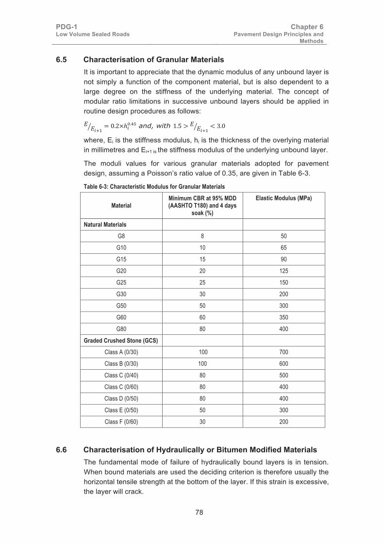
PDG-1 Low Volume Sealed Roads
Chapter 6 Pavement Design Principles and
Methods
78
6.5 Characterisation of Granular Materials It is important to appreciate that the dynamic modulus of any unbound layer is not simply a function of the component material, but is also dependent to a large degree on the stiffness of the underlying material. The concept of modular ratio limitations in successive unbound layers should be applied in routine design procedures as follows:
�����
� ���������� and, with ��� � �
����� ���
where, Ei is the stiffness modulus, hi is the thickness of the overlying material in millimetres and Ei+1 is the stiffness modulus of the underlying unbound layer.
The moduli values for various granular materials adopted for pavement design, assuming a Poisson’s ratio value of 0.35, are given in Table 6-3.
Table 6-3: Characteristic Modulus for Granular Materials
Material Minimum CBR at 95% MDD (AASHTO T180) and 4 days
soak (%)
Elastic Modulus (MPa)
Natural Materials
G8 8 50
G10 10 65
G15 15 90
G20 20 125
G25 25 150
G30 30 200
G50 50 300
G60 60 350
G80 80 400
Graded Crushed Stone (GCS)
Class A (0/30) 100 700
Class B (0/30) 100 600
Class C (0/40) 80 500
Class C (0/60) 80 400
Class D (0/50) 80 400
Class E (0/50) 50 300
Class F (0/60) 30 200
6.6 Characterisation of Hydraulically or Bitumen Modified Materials The fundamental mode of failure of hydraulically bound layers is in tension. When bound materials are used the deciding criterion is therefore usually the horizontal tensile strength at the bottom of the layer. If this strain is excessive, the layer will crack.
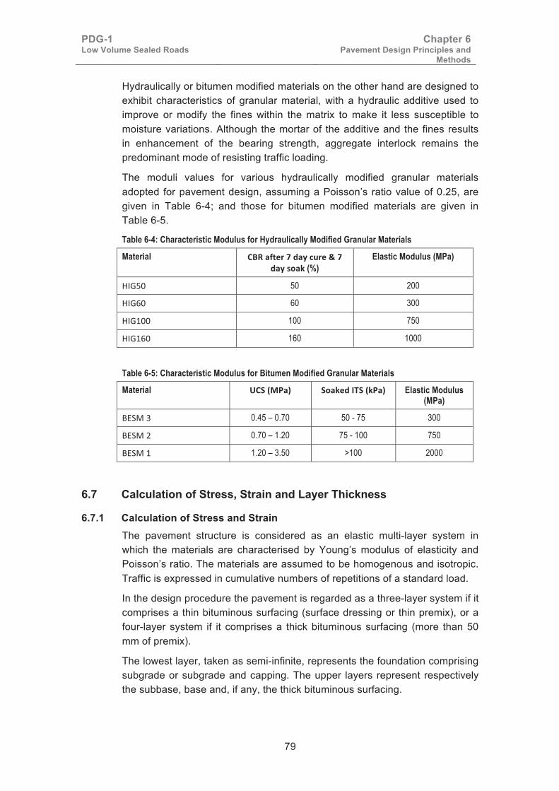
PDG-1 Low Volume Sealed Roads
Chapter 6 Pavement Design Principles and
Methods
79
Hydraulically or bitumen modified materials on the other hand are designed to exhibit characteristics of granular material, with a hydraulic additive used to improve or modify the fines within the matrix to make it less susceptible to moisture variations. Although the mortar of the additive and the fines results in enhancement of the bearing strength, aggregate interlock remains the predominant mode of resisting traffic loading.
The moduli values for various hydraulically modified granular materials adopted for pavement design, assuming a Poisson’s ratio value of 0.25, are given in Table 6-4; and those for bitumen modified materials are given in Table 6-5.
Table 6-4: Characteristic Modulus for Hydraulically Modified Granular Materials
Material ������������������� ������� ��! (%)
Elastic Modulus (MPa)
89:�� 50 200
89:�� 60 300
89:�� 100 750
89:��� 160 1000
Table 6-5: Characteristic Modulus for Bitumen Modified Granular Materials
Material "#�$�%�&� #��!���'�#�$!%�& Elastic Modulus (MPa)
,;�)��� 0.45 – 0.70 50 - 75 300
,;�)��� 0.70 – 1.20 75 - 100 750
,;�)��� 1.20 – 3.50 >100 2000
6.7 Calculation of Stress, Strain and Layer Thickness
6.7.1 Calculation of Stress and Strain The pavement structure is considered as an elastic multi-layer system in which the materials are characterised by Young’s modulus of elasticity and Poisson’s ratio. The materials are assumed to be homogenous and isotropic. Traffic is expressed in cumulative numbers of repetitions of a standard load.
In the design procedure the pavement is regarded as a three-layer system if it comprises a thin bituminous surfacing (surface dressing or thin premix), or a four-layer system if it comprises a thick bituminous surfacing (more than 50 mm of premix).
The lowest layer, taken as semi-infinite, represents the foundation comprising subgrade or subgrade and capping. The upper layers represent respectively the subbase, base and, if any, the thick bituminous surfacing.
PDG-1 Low Volume Sealed Roads
Chapter 6 Pavement Design Principles and
Methods
80
The calculation of stress, strain and deflection is based on the method of Jones2, with the following assumptions:
(i). The design load is assumed to be uniformly distributed over one circular area.
(ii). The hydraulically modified and bound pavement materials have a Poisson’s ratio equal to 0.25.
(iii). The subgrade and granular pavement materials have a Poisson’s ratio equal to 0.35.
(iv). All layers are considered to have complete friction between them.
The Shell computer program BISAR was used to calculate the horizontal tensile stress and strain at the bottom of each layer made of bound material, and the vertical compressive stress and strain in the surface of each layer, including the foundation surface.
Design axle loads of 80 kN were used.
6.7.2 Determination of Layer Thicknesses The thicknesses of the capping layers were determined using the structural number method.
The pavement layer thicknesses are determined based on empirical methods and adjusted for compliance with the permissible strains using the analytical method in 6.6.1 above, as follows:
(i) In the case of flexible pavements, the total pavement thickness required has been determined by a comparison between the compressive strain applied to the subgrade and the maximum permissible strain, which depends on the number of load applications; and
(ii) In the case of bound materials, the thickness required for each individual layer has been determined by a comparison between the tensile strain at the bottom of the layer and the maximum permissible strain, as deduced from the fatigue law of the material. In addition, it has been checked that compressive strain on the subgrade does not exceed the permissible value.
�
2 A. Jones: Tables of stresses in 3-layer elastic systems – Highway Research Bulletin 342 (1962).

PDG-1 Low Volume Sealed Roads
Chapter 7 Shoulders, Drainage & Cross-sections
81
Chapter 7: Pavement Cross Sections and Drainage
7.1 Shoulders
7.1.1 Functions and Purposes of Shoulders The purposes of shoulders are as follows:
(i). Shoulders help improve safety by providing better visibility, providing a travel area for non-motorised traffic, and a standing area for broken down vehicles.
(ii). To give added width to the carriageway for emergency use.
(iii). Providing lateral support to the pavement layers.
(iv). To assist in the removal of surface water from the carriageway and, in particular, to protect the edges of the subgrade against soaking. They should also, if necessary, facilitate the internal drainage of pavement layers.
Shoulders should therefore have sufficient strength to carry occasional traffic, be impervious to surface water, be properly shaped so as to shed water completely and be erosion resistant.
7.1.2 Different Types of Shoulders and Materials For low-volume roads, the following types of shoulders may be used:
(i). Extended bases and sub-base. This is the easiest to construct but may be costly if the base and sub-base materials are expensive. It also provides good drainage of the pavement layers. If the base consists of cohesive material, such as plastic gravel or cement (or lime) treated material, the shoulders may be left unsurfaced. If the base consists of cohesionless material, such as graded crushed stone or non-plastic gravel, the shoulders must be primed and sealed. A single or double surface dressing may be necessary, depending on trafficking conditions.
(ii). Cement or lime treated materials provide good shoulders for temporary running and keep water out of the pavement layers, but this kind of shoulder is expensive for low-volume roads.
(iii). Gravel shoulders consist of gravel, weathered rock or soft stone complying to the material specifications given below.
(iv). Earth Shoulders are advantageous because they are cheap and mostly cohesive in nature to minimise the ingress of water into the pavement layers.
PDG-1 Low Volume Sealed Roads
Chapter 7 Shoulders, Drainage & Cross-sections
82
7.1.3 Shoulder Material Requirements For graded crushed stone the material characteristics should be the same as used for base courses. For soils the characteristics should be as for material of G15, and for gravel shoulders the materials should be as follows:
− CBR at 95% MDD (AASHTO T180) and 4 days soak to a minimum of 20
− Grading should be as for gravel wearing courses (G20)
− Plasticity index: Minimum 5 and Maximum 25
− Plasticity Modulus: Minimum 200 – Maximum 1000
7.1.4 Protection of Shoulder Surfacing In order to minimise water ingress into the pavement layers under the wheel path, it is advisable that the shoulder should be sealed with at least one layer of the same bituminous material used on the carriageway. This often becomes economical by providing a safe travel area for non-motorised traffic and by extending the life of the pavement layers. In other cases where for some reason sealing is not carried out, the following protection may apply:
(i). Topsoiling and grassing: After construction, 20 mm of humus is applied on the surface and grass of the “runner type” is planted or seeded. This type of treatment is best used in wet areas. There should be a drop of 20 mm between the edge of the carriageway and the shoulder.
(ii). Priming and sanding: After the final trimming and compaction, the shoulders shall be primed with fluid cut-back. If necessary, the primed surface shall be choked by sanding.
(iii). Surface dressing: This has the advantage as an extension of one layer of a bituminous surface, as discussed above.
(iv). Deterrence: Rumble strips may deter vehicles from running on shoulders, but are a safety hazard for non-motorised traffic that use the shoulders and therefore should not be used in areas with significant volumes of non-motorised traffic.
7.1.5 Kerbs Kerbs at the edge of the carriage-way are the best protection for edge-ravelling. Their use should be considered for all roads carrying heavy traffic subjected to frequent non-authorised entry and exit where there is frequent stopping on shoulders, and in town sections.
7.2 Pavement Drainage
7.2.1 Drainage of Road Surface and Shoulders Materials used for Low-volume roads are mostly natural soils and gravels. Many of these materials are highly sensitive to moisture. It is therefore important to ensure that the road profile is well-drained. Low volume sealed
PDG-1 Low Volume Sealed Roads
Chapter 7 Shoulders, Drainage & Cross-sections
83
roads shall be constructed to have a minimum camber of 3%, but under all circumstances this shall not exceed 3.25%. The shoulders shall have a camber of 4%. Pavement material should be extended to shoulders where the specified shoulder width is less than 1.5 metres. It is further recommended that the shoulders should be sealed.
The minimum depth of side drains below formation in cuts and low fills should be 0.4m. Trapezoidal drains are recommended to increase capacity and may be widened for stone pitched or cobble stone surfaced access junctions to avoid construction of concrete pipe culverts.
To prevent water from entering the pavement edges, the extra width of base must be primed and sealed. The edge of the seal should also cover 200 mm of the shoulder.
7.2.2 Internal Drainage of Pavement Layers When permeable base materials are used, the “trench” type of cross-section, in which the pavement layers are confined between continuous impermeable shoulders, must be avoided. This applies principally to stone bases. In all cases where the base material is permeable, the best solution is to extend both the base and sub-base through to the shoulders. This approach is inexpensive for low-volume roads since their shoulders are often less than 1.5 m.
In cases where the base material is impervious, provided that the shoulders are sufficiently impervious and the joint between base and shoulder is properly sealed, internal drainage should not be necessary. However, if this cannot be assured then drainage must be considered.
7.3 Pavement Cross-sections
7.3.1 Carriageway Dimensions Carriageway dimensions for low-volume roads shall be selected from Chapter 4 of the Road Design Manual Part I, Geometric Design of Rural Roads, 1979. In any case, the carriageway shall not be wider than 8 m, including shoulders. Shoulders shall not be wider than 1.5 m for each side of the carriageway.
Low volume sealed roads shall be constructed to have a minimum camber of 3%, but under all circumstances this shall not exceed 3.25%. The shoulders shall have a camber of 4%.
7.3.2 Shoulder Widths For low-volume roads, shoulders shall be less than 1.5 m wide. The shoulders should simply be an extension of the base and sub-base. It is recommended that these shoulders should be primed and sealed – especially for cohesionless materials.
In areas with a high volume of pedestrians, other non-motorised traffic, and motorcycles, the shoulders should be widened to 3.0 m either side of the road.

PDG-1 Low Volume Sealed Roads
Chapter 7 Shoulders, Drainage & Cross-sections
84
7.3.3 Edge Restraint It is essential that the edges of the road bases be provided with sufficient lateral support so that they can resist the stresses applied by heavy vehicles. This problem is particularly serious in the case of cohesionless materials such as graded crushed stone. In this respect it should also be noted that proper compaction of the edges is difficult and lower densities frequently result.
Two possible solutions are available as below:
(i). Providing extra base width of 200 – 300 mm either side. This extra width shall be primed and sealed, together with the inner edge of the shoulder.
(ii). Concrete kerbs may be placed instead of the extra width. However, these kerbs are expensive and can be justified only in the case of a graded crushed stone base or in urban areas. Moreover, they create a discontinuity along the edges, with possible cracking and subsequent water ingress. Kerbs along the road base are therefore recommended only where a pervious sub-base is laid.
7.3.4 Shoulder Slopes in Areas of Expansive Clay Subgrades It is important that slopes of embankments constructed on expansive clay (black cotton) subgrades be protected by a blanket of material that is non-swelling, impermeable, and fairly resistant to erosion. A material of S3 quality is usually sufficient. The blanket thickness should be at least 300 mm. In this case the following slopes can be adopted:
Provided that the embankments are covered with a protective soil blanket, the following slopes (expressed as vertical:horizontal) are recommended:
− Cohesionless sands 1:3 if < 1 m
1:2 if > 1 m
− Other materials 1:3 if h < 1 m
1:2 if 1 < h < 3 m
1:1.5 if 0 < h < 10 m
Where h is the height of embankment
Black cotton soils may also be used to form shallow embankments (up to about 3 m), provided that a protective blanket is placed on the slopes, to prevent moisture changes in the black cotton soil.
The vast majority of embankments up to 8 m in height and resting on non-saturated soils have their slope angles determined by either experience or “rule of thumb”.
If black cotton soils are left exposed, as may be the case in shallow cuttings or side ditches, it is recommended that the slope does not exceed 1 (vertical) : 4 (Horizontal). Unprotected, black cotton soils are prone to erosion and also to creep due to lateral expansion movements. Safe slopes in black cotton soils should therefore be very gentle (1:6 where land is available).

PDG-1 Low Volume Sealed Roads
Chapter 8 Design Catalogue
85
Chapter 8: Design Catalogue
8.1 Introduction Selection of the possible types of pavement has been based on the following principles:
• The sub-base material should not be of unnecessarily higher standard than the base material.
• It is unsafe to place expensive bound materials on natural materials which are often deformable and heterogeneous, or on materials whose moduli are less than one tenth of the modulus of the base.
8.2 The Standard Pavement Structures Fourteen pavement combinations and the applicable traffic classes are as shown in Table 8-1. For each of the 14 types of pavement considered, the design for each class of soil and each class of traffic is presented in one chart. Brief comments on the peculiarities, advantages and disadvantages of each type of pavement have been given. The pavement materials required for use in each chart have been indicated and referenced to materials specification charts.
Table 8-1: Guide to Pavement Type Selection
No Pavement Materials Traffic Application of
Catalogue Road Base Sub-base
LV1 G30 Not required T5-3, T5-4
LV2 G50 G25 T5-1, T5-2
LV3 G80 G30 T5-0
LV4 HIG60 Not required T5-3, T5-4
LV5 HIG100 G25 T5-1, T5-2
LV6 HIG160 G30 T5-1, T5-2
LV7 HIG100 HIG50 T5-0
LV8 HIG160 HIG60 T5-0
LV9 BESM 3 G25 T5-0, T5-1, T5-2
LV10 BESM 3 G30 T5-0
LV11 Hand packed stone G30 T5-0
LV12 Interlocking Cobblestone Base/Surfacing G30 T5-0, T5-1, T5-2
LV13 Interlocking Concrete Block Base/Surfacing G30 T5-0, T5-1, T5-2
LV14 Concrete Pavement Base/Surfacing G30 T5-0, T5-1, T5-2
8.3 The Use of Other Types of Pavement The 14 types of pavement design shown in this guideline are considered to cover virtually all the bitumen road designs required in Kenya. Nevertheless, the design and construction of other types of pavement materials is not

PDG-1 Low Volume Sealed Roads
Chapter 8 Design Catalogue
86
precluded. Indeed, the use of other kinds of pavement materials may be warranted by local circumstances or economic considerations.
In such special cases the design engineer should follow the design and construction principles set out in this guideline and liaise closely with the Materials Testing and Research Division of the Ministry of Transport and Infrastructure.
8.4 Method of Use The following steps shall be taken in the use of these charts to arrive at a suitable pavement structure for a given set of conditions:
(i). Determine the design traffic class as described in Chapter 2.
(ii). Determine the native subgrade class as described in Chapter 3.
(iii). Conduct a study of available road construction materials; including materials for capping.
(iv). Select a suitable pavement foundation, based on available capping materials.
(v). Prepare pavement design options, based on the available materials.
(vi). Conduct cost and technical comparisons of the pavement design options.
(vii). Select the most appropriate pavement design and prepare construction specifications.
8.4.1 Pavement Structure Type LV1 (G30 Base) This is a flexible pavement structure; highly economic for use. However, base quality natural gravels are scarce in Kenya. In many cases, mechanical stabilisation may be necessary to achieve a material complying with the specification.
Materials
Base Materials: Lateritic gravel, quartzitic gravel, “soft stone”, calcareous gravel, coral rag, scarified pavement material or milled bituminous pavement material.
Materials Specifications and Construction Procedures
Surfacing: - See charts S1, S2, S3, S5, or S6. Combination seals strongly advised as in section 5.12.6.
Natural gravels for base: See chart GM6.
Capping layers: - See charts GM1, GM2, GM3, and GM4.
�
�
� �

PDG-1 Low Volume Sealed Roads
Chapter 8 Design Catalogue
87
�
����(��(����)*)����������)���) �+���)�������������� ������������������ ����+,������<��.��<1������)������� �
�,-. �,-/ �,-0 �,-+ �,-1
�+
�0
�/
�.
*������� �������� ����������������)��� ����2���(�������()�) �*)��
��4�/4�/��4�;�;�������+���;���������������;���4/�
���������������� � ���2��()���������� � � ��(��� ����������� �
=�<�<<
�/�/
=��= �
�/�/
=<< =���/
�/
=<< =<<�/ �/
�)�������������)
������3������ ���������456
�= ��!���
���" #��$<<< �� ��!�=<
���� ��$<<<���=<<$<<< �� �!�=� �= %� ��
���� =<<$<<<�!���<$<<< �" =<�!�=& �� '< �"
���= ��<$<<<�!��<<$<<< �� =��!��< �� =�� ��
���< �<<$<<<�!�=����� �% >�< �" ��< �%
�� "<< �
������������ ����������)��������������3��3�� ��� �!��3���!��
(����������)���������
*!3�����4*��6)����������
������3������
���((�����)�� �& �=< �=< �=� �=� �=< �=� ��� ��< �=� ��� ��< ��� ��< ��<�*+, �--�.��1 �<< � � ��< =�< =�< =<< = � �<< ��� =<< =�< = � =<< =�� =<<��.�����)�� �& �=<�*+, �--�.��1 �<< = �
�� �� �� �� �� �� �" �� �% �" �� �% �� �% �%��"�!��3�������3������
+�(( /
�!��3���!�����3���"�!��3�������3��(�����
�������������3������ ���= �� �"

PDG-1 Low Volume Sealed Roads
Chapter 8 Design Catalogue
88
8.4.2 Pavement Structure Type LV2 (G50 Base/G25 Sub-base) This is a flexible pavement structure; highly economic for use. However base quality natural gravels are scarce in Kenya. In many cases, mechanical stabilisation may be necessary to achieve a material complying with the specification.
Materials
Base Materials: Lateritic gravel, quartzitic gravel, “soft stone”, calcareous gravel, coral rag, scarified pavement material or milled bituminous pavement material.
Sub-base Materials: Lateritic gravel, quartzitic gravel, “soft stone”, calcareous gravel, coral rag, and clayey/silty sand.
Materials Specifications and Construction Procedures
Surfacing: - See charts S1, S3, or S4. Must be double seals or Combination seals as in section 5.12.6.
Natural gravels for base: See chart GM7.
Graded crushed stone for base: GM9 - Class E.
Natural gravels for sub-base: See chart GM5.
Capping layers: - See charts GM1, GM2, GM3, and GM4.
�
�
� �

PDG-1 Low Volume Sealed Roads
Chapter 8 Design Catalogue
89
�
����(��(����)�)��������)���) ������)������������� ������������������ ����+,������<��.��<1�����)������ ������������������ ����+,���������.���1
�7�� �7�� �7�� �7�� �7��
��
��
��
��
��������������������������������)�������2���(������()�)����)��
��4�/4�/��4�;�;�������+���;���������������;���4/�
������������������� ��2��()������������� ���(������������������
=<< =�<
=�<=�<
�/�/
=���<<
=�<�/
�/
=�< = �
�/�/
=�< = �
�/�/
�)�
���
����
�����
�)
)��
����������
����)(
���((�����)�� �& �=< �=< �=� �=� �=< �=� ��� ��< �=� ��� ��< ��� ��< ��<�*+, �--�.��1 �<< � � ��< =�< =�< =<< = � �<< ��� =<< =�< = � =<< =�� =<<��.�����)�� �& �=<�*+, �--�.��1 �<< = �
�� �� �� �� �� �� �" �� �% �" �� �% �� �% �%����������� !�"���#"$$
+�(( /
���%�"&'�%$�"%������������� !�"���(�$'!%
�"&'����� !�"���#"$$ ���= �� �"
�� !�"���#"$$ ����"%!��(8)
�= ��!���
���" #��$<<< �� ��!�=<
���� ��$<<<���=<<$<<< �� �!�=� �= %� ��
���� =<<$<<<�!���<$<<< �" =<�!�=& �� '< �"
���= ��<$<<<�!��<<$<<< �� =��!��< �� =�� ��
���< �<<$<<<�!�=����� �% >�< �" ��< �%
�� "<< �
��"**'+�#"$$ ���#"&'���),�'�"#�%&��&"%�"����-#�$ ���%�"&'�%�
(�$'!%�#"$$)**�+&'���
����#�$�(��")),�'�"#�%&�
�� !�"���#"$$
PDG-1 Low Volume Sealed Roads
Chapter 8 Design Catalogue
90
8.4.3 Pavement Structure Type LV3 (G80 Base/G30 Sub-base) This is a flexible pavement structure; highly economic for use. However base quality natural gravels are scarce in Kenya. In many cases, mechanical stabilisation may be necessary to achieve a material complying with the specification.
Materials
Base Materials: Lateritic gravel, quartzitic gravel, “soft stone”, calcareous gravel, coral rag, scarified pavement material or milled bituminous pavement material.
Sub-base Materials: Lateritic gravel, quartzitic gravel, “soft stone”, calcareous gravel, coral rag, and clayey/silty sand, scarified pavement material or milled bituminous pavement material.
Materials Specifications and Construction Procedures
Surfacing: - See charts S1, S3, or S4. Must be double seals or Combination seals as in section 5.12.6.
Natural gravels for base: See chart GM8.
Graded crushed stone for base: GM9 - Class D.
Natural gravels for sub-base: See chart GM6.
Capping layers: - See charts GM1, GM2, GM3, GM4, and GM5.
�
� �

PDG-1 Low Volume Sealed Roads
Chapter 8 Design Catalogue
91
�
����(��(����)�)��������)���) ���
���)������������� ������������������ ����+,�����&<��.�&<1�����)������ ������������������ ����+,������<��.��<1
�7�� �7�� �7�� �7�� �7��
��
��
��
��
��������������������������������)�������2���(������()�)����)��
��4�/4�/��4�;�;�������+���;���������������;���4/�
������������������� ��2��()������������� ���(������������������
= �
=�<
�/
=��
=�<
�/
=<<
=��
�/
= �
�/
)����������������)(
�� !�"���#"$$ ����"%!��(8)
�= ��!���
���" #��$<<< �� ��!�=<
���� ��$<<<���=<<$<<< �� �!�=� �= %� ��
���� =<<$<<<�!���<$<<< �" =<�!�=& �� '< �"
���= ��<$<<<�!��<<$<<< �� =��!��< �� =�� ��
���< �<<$<<<�!�=����� �% >�< �" ��< �%
�� "<< �
��"**'+�#"$$ ���#"&'���),�'�"#�%&��&"%�"����-#�$ ���%�"&'�%�
(�$'!%�#"$$)**�+&'���
����#�$�(��")),�'�"#�%&�
�� !�"���#"$$
���((�����)�� �& �=< �=< �=� �=� �=< �=� ��� ��< �=� ��� ��< ��� ��< ��<�*+, �--�.��1 �<< � � ��< =�< =�< =<< = � �<< ��� =<< =�< = � =<< =�� =<<��.�����)�� �& �=<�*+, �--�.��1 �<< = �
�� �� �� �� �� �� �" �� �% �" �� �% �� �% �%����������� !�"���#"$$
+�(( /
���%�"&'�%$�"%������������� !�"���(�$'!%
�"&'����� !�"���#"$$ ���= �� �"
PDG-1 Low Volume Sealed Roads
Chapter 8 Design Catalogue
92
8.4.4 Pavement Structure Type LV4 (HIG60 Base) This pavement structure is comparatively economic and materials suitable for treatment can be found in most regions of Kenya. However, specific difficulties may arise in arid areas due to lack of water, excessive evaporation and shrinkage.
These structures are essentially flexible. Care must be taken to ensure that the base material is not too rigid, as this would result in overstressing and cracking of the base. The base modulus should not exceed 3x10⁶ kN/m2.
Materials
Base Materials: Hydraulically improved natural gravel or clayey/silty sand. The natural gravel can be lateritic gravel, quartzitic gravel, or other suitable gravel of G20 or G25 quality.
Materials Specifications and Construction Procedures
Surfacing: - See charts S1, S2, S3, S4, or S5. Combination seals strongly advised as in section 5.12.6.
Hydraulically improved natural gravels for base: See chart HIG-2.
Capping layers: - See charts GM1, GM2, GM3, GM4, GM5, and GM6.
�
�
� �

PDG-1 Low Volume Sealed Roads
Chapter 8 Design Catalogue
93
�
����(��(����)*)����������)���) �.���)�������������� �������������� ����������������������+,��������������������)������� �
�,-. �,-/ �,-0 �,-+ �,-1
�+
�0
�/
�.
���������������� � ���2��()���������� � � ��(��� ����������� �
*������� �������� ����������������)��� ����2���(�������()�) �*)��
��4�/4�/��4�;�;�������+���;�� !��"!#��!"��;��!4/�
������
�/�/
���
�/�/
� ����/
�/
� �
�/ �/
�)�������������)
��� ���"���� � �� �� ��� ��� �� ��� ��� �� ��� ��� �� ��� �� ���$%��&&����� � ��� �� �� �� � ��� � ��� � �� ��� � ��� �"�'���"���� � ���$%��&&����� � ���
�� �� �� �� �� �� �� �� �� �� �� �� �� �� ����"�!��3�������3������
+� �(
�!��3���!�����3���"�!��3�������3��(�����
�������������3������ ���� �� ��
������3������ ���������456
�� ��)���
���� ?��* �� ��)��
���� ��*����* �� ��)��� � �� ��
���� �*�)���* �� ��)�� � + ��
���� ��*�)��* �� ���)�� � ��� ��
��� �*�)�������� �� @� � �� ��
� � �
������������ ����������)��������������3��3�� ��� �!��3���!��
(����������)���������
*!3�����4*��6)����������
������3������

PDG-1 Low Volume Sealed Roads
Chapter 8 Design Catalogue
94
8.4.5 Pavement Structure Type LV5 (HIG100 Base/G25 Sub-base) This pavement structure is comparatively economic and materials suitable for treatment can be found in most regions of Kenya. However, specific difficulties may arise in arid areas due to lack of water, excessive evaporation and shrinkage.
These structures are essentially flexible. Care must be taken to ensure that the base material is not too rigid, as this would result in overstressing and cracking of the base. The base modulus should not exceed 3X10⁶ kN/m2.
Materials
Base Materials: Hydraulically improved natural gravel or clayey/silty sand. The natural gravel can be lateritic gravel, quartzitic gravel, or other suitable gravel of G20 or G25 quality. If the foundation class is F4 and the treated material is clayey sand or other fine material, then the base thickness may be reduced to 100 mm.
Sub-base Materials: Lateritic gravel, quartzitic gravel, “soft stone”, calcareous gravel, coral rag, and clayey/silty sand.
Materials Specifications and Construction Procedures
Surfacing: - See charts S1, S3, or S4. Must be double seals or combination seals, as in section 5.12.6.
Hydraulically improved natural gravels for base: See chart HIG-3.
Natural gravels for sub-base: See chart GM5.
Capping layers: - See Charts GM1, GM2, GM3, and GM4.
�
� �

PDG-1 Low Volume Sealed Roads
Chapter 8 Design Catalogue
95
�
����(��(����)�)��������)���) ��7���)������������� ���������������� ����������� ����������+,�� �������������������)������ ���������������� ����������+,�� �����������
�7�� �7�� �7�� �7�� �7��
��
��
��
��
��������������������������������)�������2���(������()�)����)��
��4 /4�/�!4";�; �����#+�#�;��$%��&%'�"%&#�;��%4/�
������������������� ��2��()������������� ���(������������������
��� ���
������
�/�/
��� ���
��� ����/
�/
������
����/
�/
��� ���
�/ �/�)�
���
����
�����
�)
)��
����������
����)(
�� !�"���#"$$ ����"%!��(8)
�� ��(���
��)* +��,��� �� ��(���
��)- ��,����)����,��� �- .�(��- $� /� �-
��)� ���,����(����,��� �* ���(��0 $� 1� �*
��)� ���,����(����,��� �� ���(�-� $- ��� ��
��)� ���,����(�������� � �/ A-� $* ��� �/
$� *�� )
��"**'+�#"$$ ���#"&'���),�'�"#�%&��&"%�"����-#�$ ���%�"&'�%�
(�$'!%�#"$$)**�+&'���
����#�$�(��")),�'�"#�%&�
�� !�"���#"$$
��#�����&���� �0 ��� ��� ��� ��� ��� ��� ��� �-� ��� ��� �-� ��� �-� �-��2�3��44����� -�� �.� -�� ��� ��� ��� �.� ��� ��� ��� ��� �.� ��� ��� ���& 5���&���� �0 ����2�3��44����� ��� �.�
�� �� �- �- �- �- �* �� �/ �* �� �/ �� �/ �/����������� !�"���#"$$
+�����6
���%�"&'�%$�"%������������� !�"���(�$'!%
�"&'����� !�"���#"$$ ���� �- �*

PDG-1 Low Volume Sealed Roads
Chapter 8 Design Catalogue
96
8.4.6 Pavement Structure Type LV6 (HIG160 Base/G30 Sub-base) This pavement structure is comparatively economic and materials suitable for treatment can be found in most regions of Kenya. However, specific difficulties may arise in arid areas due to lack of water, excessive evaporation and shrinkage.
These structures are essentially flexible. Care must be taken to ensure that the base material is not too rigid, as this would result in overstressing and cracking of the base. The base modulus should not exceed 3X10⁶ kN/m2.
Materials
Base Materials: Hydraulically improved natural gravel or clayey/silty sand. The natural gravel can be lateritic gravel, quartzitic gravel, or other suitable gravel of minimum quality G25 before treatment.
Sub-base Materials: Lateritic gravel, quartzitic gravel, “soft stone”, calcareous gravel, coral rag, and clayey/silty sand, scarified pavement material or milled bituminous pavement material.
Materials Specifications and Construction Procedures
Surfacing: - See charts S1, S3, or S4. Must be double seals or Combination seals as in section 5.12.6.
Hydraulically improved natural gravels for base: See chart HIG-4.
Natural gravels for sub-base: See chart GM6.
Capping layers: - See charts GM1, GM2, GM3, GM4, and GM5.
� �

PDG-1 Low Volume Sealed Roads
Chapter 8 Design Catalogue
97
�
����(��(����)�)��������)���) ��.���)������������� ���������������� ����������� ����������+,�� ���/�������/�������)������ ���������������� ����������+,�� ��-�����-��
�9�/ �9�# �9�$ �9�% �9�&
�%
�$
�#
�/
��������������������������������)�������2���(������()�)����)��
��4 /4�/�!4";�; �����#+�#�;��$%��&%'�"%&#�;��%4/�
������������������� ��2��()������������� ���(������������������
�.�
���
�/
���
���
�/
���
���
�/
���
�/
)����������������)(
��#�����&���� �0 ��� ��� ��� ��� ��� ��� ��� �-� ��� ��� �-� ��� �-� �-��2�3��44����� -�� �.� -�� ��� ��� ��� �.� ��� ��� ��� ��� �.� ��� ��� ���& 5���&���� �0 ����2�3��44����� ��� �.�
�� �� �- �- �- �- �* �� �/ �* �� �/ �� �/ �/����������� !�"���#"$$
+�����6
���%�"&'�%$�"%������������� !�"���(�$'!%
�"&'����� !�"���#"$$ ���� �- �*
�� !�"���#"$$ ����"%!��(:)
�� ��(���
��)* +��,��� �� ��(���
��)- ��,����)����,��� �- .�(��- $� /� �-
��)� ���,����(����,��� �* ���(��0 $� 1� �*
��)� ���,����(����,��� �� ���(�-� $- ��� ��
��)� ���,����(�������� � �/ A-� $* ��� �/
$� *�� )
��"**'+�#"$$ ���#"&'���),�'�"#�%&��&"%�"����-#�$ ���%�"&'�%�
(�$'!%�#"$$)**�+&'���
����#�$�(��")),�'�"#�%&�
�� !�"���#"$$

PDG-1 Low Volume Sealed Roads
Chapter 8 Design Catalogue
98
8.4.7 Pavement Structure Type LV7 (HIG100 Base/HIG50 Sub-base) This pavement structure is comparatively economic and materials suitable for treatment can be found in most regions of Kenya. However, specific difficulties may arise in arid areas due to lack of water, excessive evaporation and shrinkage.
These structures are essentially flexible. Care must be taken to ensure that the base material is not too rigid, as this would result in overstressing and cracking of the base. The base modulus should not exceed 3X10⁶ kN/m2.
Materials
Base Materials: Hydraulically improved natural gravel or clayey/silty sand. The natural gravel can be lateritic gravel, quartzitic gravel, or other suitable gravel of minimum quality G20 before treatment.
Sub-base Materials: Hydraulically improved natural gravel or clayey/silty sand. The material before treatment should be of G15 or G20 quality.
Materials Specifications and Construction Procedures
Surfacing: - See charts S1, S3, or S4. Must be double seals or Combination seals as in section 5.12.6.
Hydraulically improved gravels for base: See chart HIG-3.
Hydraulically improved gravels sub-base: See chart HIG-1.
Capping layers: - See charts GM1, GM2, GM3, GM4, GM5, and GM6.
�
� �

PDG-1 Low Volume Sealed Roads
Chapter 8 Design Catalogue
99
�
����(��(����)�)��������)���) ��0���)������������� ���������������� ����������� ����������+,�� ���7�����������)������ ���������������� ����������� ����������+,�� ���7������
�7�� �7�� �7�� �7�� �7��
��
��
��
��
��������������������������������)�������2���(������()�)����)��
��4 /4�/�!4";�; �����#+�#�;��$%��&%'�"%&#�;��%4/�
������������������� ��2��()������������� ���(������������������
� ���
��� ���
�/ �/
� �
��� ���
�/ �/
����
����/
�/
��� ���
�/ �/
�� !�"���#"$$ ����"%!��(;)
�� ��)���
���� ?��* �� ��)��
���� ��*����* �� ��)��� $� �� ��
���� �*�)���* �� ��)�� $� + ��
���� ��*�)��* �� ���)�� $� ��� ��
��� �*�)�������� � �� @� $� �� ��
$� � �
��"**'+�#"$$ ���#"&'���),�'�"#�%&��&"%�"����-#�$ ���%�"&'�%�
(�$'!%�#"$$)**�+&'���
����#�$�(��")),�'�"#�%&�
�� !�"���#"$$
��#�����&���� � �� �� ��� ��� �� ��� ��� �� ��� ��� �� ��� �� ���2�3��44����� � ��� �� �� �� � ��� � ��� � �� ��� � ��� �& '���&���� � ���2�3��44����� � ���
�� �� �� �� �� �� �� �� �� �� �� �� �� �� ������������� !�"���#"$$
+�����6
���%�"&'�%$�"%������������� !�"���(�$'!%
�"&'����� !�"���#"$$ ���� �� ��
�)�
���
����
�����
�)
)��
����������
����)(

PDG-1 Low Volume Sealed Roads
Chapter 8 Design Catalogue
100
8.4.8 Pavement Structure Type LV8 (HIG160 Base/HIG60 Sub-base) This pavement structure is comparatively economic and materials suitable for treatment can be found in most regions of Kenya. However, specific difficulties may arise in arid areas due to lack of water, excessive evaporation and shrinkage.
These structures are essentially flexible. Care must be taken to ensure that the base material is not too rigid, as this would result in overstressing and cracking of the base. The base modulus should not exceed 3X10⁶ kN/m2.
Materials
Base Materials: Hydraulically improved natural gravel or clayey/silty sand. The natural gravel can be lateritic gravel, quartzitic gravel, or other suitable gravel of minimum quality G25 before treatment.
Sub-base Materials: Hydraulically improved natural gravel or clayey/silty sand. The material before treatment should be of G20 or G25 quality.
Materials Specifications and Construction Procedures
Surfacing: - See charts S1, S3, or S4. Must be double seals or Combination seals as in section 5.12.6.
Hydraulically improved natural gravels for base: See chart HIG-4.
Hydraulically improved natural gravels sub-base: See chart HIG-2.
Capping layers: - See Charts GM1, GM2, GM3, GM4, GM5, and GM6.
� �

PDG-1 Low Volume Sealed Roads
Chapter 8 Design Catalogue
101
�
����(��(����)�)��������)���) ��'���)������������� ���������������� ����������� ����������+,�� ����7������������)������ ���������������� ����������� ����������+,�� ���7������
�9�/ �9�# �9�$ �9�% �9�&
�%
�$
�#
�/
��������������������������������)�������2���(������()�)����)��
��4 /4�/�!4";�; �����#+�#�;��$%��&%'�"%&#�;��%4/�
������������������� ��2��()������������� ���(������������������
��
���
�/
�
���
�/
�
���
�/
���
�/
)����������������)(
��#�����&���� � �� �� ��� ��� �� ��� ��� �� ��� ��� �� ��� �� ���2�3��44����� � ��� �� �� �� � ��� � ��� � �� ��� � ��� �& '���&���� � ���2�3��44����� � ���
�� �� �� �� �� �� �� �� �� �� �� �� �� �� ������������� !�"���#"$$
+�����6
���%�"&'�%$�"%������������� !�"���(�$'!%
�"&'����� !�"���#"$$ ���� �� ��
�� !�"���#"$$ ����"%!��(:)
�� ��)���
���� ?��* �� ��)��
���� ��*����* �� ��)��� $� �� ��
���� �*�)���* �� ��)�� $� + ��
���� ��*�)��* �� ���)�� $� ��� ��
��� �*�)�������� � �� @� $� �� ��
$� � �
��"**'+�#"$$ ���#"&'���),�'�"#�%&��&"%�"����-#�$ ���%�"&'�%�
(�$'!%�#"$$)**�+&'���
����#�$�(��")),�'�"#�%&�
�� !�"���#"$$
PDG-1 Low Volume Sealed Roads
Chapter 8 Design Catalogue
102
8.4.9 Pavement Structure Type LV9 (BESM 3 Base/G25 Sub-base) This type of pavement structure is comparatively expensive due to the use of expensive bitumen emulsion to treat the neat materials. Nevertheless, this type of pavement offers protection to materials with fines that are highly susceptible to moisture change (in wet climatic conditions).
In arid areas, materials treated with bitumen are generally preferable to those treated with cement.
These structures are flexible in nature.
In order for this type of pavement to perform satisfactorily, special care should be taken to ensure uniformity and compaction of the mix.
Materials
Base Materials: Bitumen emulsion treated natural gravel or clayey/silty sand, scarified pavement material or milled bituminous pavement material. The natural gravel can be lateritic gravel, quartzitic gravel, or other suitable gravel of G30 minimum quality. Pre-treatment with lime may be required to reduce the PI of the natural material.
Sub-base Materials: Lateritic gravel, quartzitic gravel, “soft stone”, calcareous gravel, coral rag, and clayey/silty sand.
Materials Specifications and Construction Procedures
Surfacing: - See charts S1, S3, or S4. Must be double seals or Combination seals as in section 5.12.6.
Bitumen emulsion improved natural gravels for base: See chart BESM 3.
Natural gravels for sub-base: See chart GM5.
Capping layers: - See charts GM1, GM2, GM3, and GM4.
� �

PDG-1 Low Volume Sealed Roads
Chapter 8 Design Catalogue
103
�
����(��(����)�)��������)���) ��(���)������������� ,�������;��������� �����������������,;����������)������ ��������������������������+,�������������
�7�� �7�� �7�� �7�� �7��
��
��
��
��
��������������������������������)�������2���(������()�)����)��
��4�/4�/��4�;�;������ +� �;��!"��#"$��"# �;��"4/�
������������������� ��2��()������������� ���(������������������
%�� %&����
%''%''
%''�/
�/�/
%'' %��%&�
%'' %''%''�/
�/�/
%'' %'' %��
%'' %''%''
�/ �/�/
%'' %'' %''
�/ �/ �/
�� !�"���#"$$ ����"%!��(;)
�% ��(���
��)* +��,''' �� ��(�%'
��)� ��,'''�)�%'',''' �� &�(�%� !% -� ��
��)� %'','''�(���',''' �* %'�(�%. !� /' �*
��)% ��','''�(��'',''' �� %��(��' !� %�� ��
��)' �'','''�(�%������� �- A�' !* ��' �-
!� *'' )
��"**'+�#"$$ ���#"&'���),�'�"#�%&��&"%�"����-#�$ ���%�"&'�%�
(�$'!%�#"$$)**�+&'���
����#�$�(��")),�'�"#�%&�
�� !�"���#"$$
�� 00���#�1�� �. �%' �%' �%� �%� �%' �%� ��� ��' �%� ��� ��' ��� ��' ��'�2�34������� �'' �&� ��' %�' %�' %'' %&� �'' ��� %'' %�' %&� %'' %�� %''#5���#�1�� �. �%'�2�34������� �'' %&�
�� �� �� �� �� �� �* �� �- �* �� �- �� �- �-����������� !�"���#"$$
+�00��6
���%�"&'�%$�"%������������� !�"���(�$'!%
�"&'����� !�"���#"$$ ���% �� �*
)��
����������
����)(

PDG-1 Low Volume Sealed Roads
Chapter 8 Design Catalogue
104
8.4.10 Pavement Structure Type LV10 (BESM 3 Base/G30 Sub-base) This type of pavement structure is comparatively expensive due to the use of expensive bitumen emulsion to treat the neat materials. Nevertheless, this type of pavement offers protection to materials with fines that are highly susceptible to moisture change (in wet climatic conditions).
In arid areas, materials treated with bitumen are generally preferable to those treated with cement.
These structures are flexible in nature.
In order for this type of pavement to perform satisfactorily, special care should be taken to ensure uniformity and compaction of the mix.
Materials
Base Materials: Bitumen emulsion treated natural gravel or clayey/silty sand, scarified pavement material or milled bituminous pavement material. The natural gravel can be lateritic gravel, quartzitic gravel, or other suitable gravel of G30 minimum quality. Pre-treatment with lime may be required to reduce the PI of the natural material.
Sub-base Materials: Lateritic gravel, quartzitic gravel, “soft stone”, calcareous gravel, coral rag, and clayey/silty sand.
Materials Specifications and Construction Procedures
Surfacing: - AC II (10 mm aggregate and 30 mm compacted layer thickness) - See chart S7.
Bitumen emulsion improved natural gravels for base: See chart BESM 3.
Natural gravels for sub-base: See chart GM6.
Capping layers: - See charts GM1, GM2, GM3, GM4, and GM5.
� �
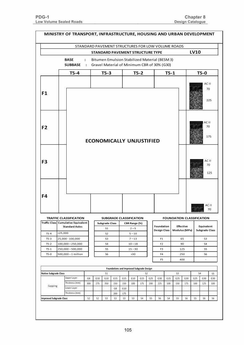
PDG-1 Low Volume Sealed Roads
Chapter 8 Design Catalogue
105
�
����(��(����)�)��������)���) �������)������������� ,�������;���4� �����������)��������,;�)� ������)������ ������)����������)�������+,����� ����� ��
�7�� �7�� �7�� �7�� �7��
��
��
��
��
��������������������������������)�������2���(������()�)����)��
��4�/4�/��4�;);�������+���;������6�����6�);���4/�
������������������� ��2��()������������� ���(������������������
!
"�
4+�99
#"!
"�4+�99
# !
"�4+�99
"�4+�99
)����������������)(
�� !�"���#"$$ ����"%!��(8)
�# �$�!�
�!%& ' !(��� � !�$�#�
�!% !(����%�#��(��� � "�$�# �# )! �
�!% #��(����$� !�(��� �& #��$�#* � +� �&
�!%# !�(����$�!��(��� �! #!�$� � � # ! �!
�!%� !��(����$�#�������� �) B � �& !� �)
�! &�� %
��"**'+�#"$$ ���#"&'���),�'�"#�%&��&"%�"����-#�$ ���%�"&'�%�
(�$'!%�#"$$)**�+&'���
����#�$�(��")),�'�"#�%&�
�� !�"���#"$$
�!�,,��6�-� �* �#� �#� �#! �#! �#� �#! � ! � � �#! � ! � � � ! � � � ��.�/0�11����� �� "! !� #!� #!� #�� #"! �� ! #�� #!� #"! #�� # ! #��6�2��6�-� �* �#��.�/0�11����� �� #"!
� � � � � � �& �! �) �& �! �) �! �) �)����������� !�"���#"$$
+�,,��3
���%�"&'�%$�"%������������� !�"���(�$'!%
�"&'����� !�"���#"$$ � �# � �&

PDG-1 Low Volume Sealed Roads
Chapter 8 Design Catalogue
106
8.4.11 Pavement Structure Type LV11 (HPS Base/G30 Sub-base) This is a flexible pavement structure; highly economic for use, especially in urban areas and other areas with frequent traffic activity such as market towns. In areas where gravel of base quality to carry traffic of T5-0 is scarce and yet large fractured rock is available, this is an ideal type of pavement. Moreover, in urban areas this provides an opportunity to employ local people in the production of construction stone and laying/packing the stone on the road. If a sufficient number of stone masons are employed the process is rapid, but if there are an insufficient number of stone masons the process can be rather slow.
This pavement requires a fairly thick bituminous surfacing (25-35 mm thick cold mix asphalt) if a good riding quality is to be guaranteed. As a result of these superior materials, if constructed well it is a very durable pavement.
Materials
Base Materials: Stones from trachyte, basalt, granite and hard sandstone.
Sub-base Materials: Lateritic gravel, quartzitic gravel, “soft stone”, calcareous gravel, coral rag, and clayey/silty sand.
Materials Specifications and Construction Procedures
Surfacing: - AC II (10 mm aggregate and 30 mm compacted layer thickness) - See chart S7.
Hand-packed stone for base: See chart B1G.
Natural gravels for sub-base: See chart GM6.
Capping layers: - See charts GM1, GM2, GM3, GM4, and GM5.
� �

PDG-1 Low Volume Sealed Roads
Chapter 8 Design Catalogue
107
�
����(��(����)�)��������)���) �������)� 4���!�/0�����������)� ������5����������5�������+,������67����6�
�7�� �7�� �7�� �7�� �7��
��
��
��
��
������������������� ��2��()������������� ���(������������������
��������������������������������)�������2���(������()�)����)��
��4 /4�/�!4";5; �����#+�#�;���%��8%'�"%8#5;��%4/�
%��
%�6
4+�9 9
%66
%�6
4+�9 9
%�6
4+�9 9
%�6
4+�9 9
)����������������)(
�� !�"���#"$$ ����"%!��(8)
�% ��(���
��)* +��,666 �� ��(�%6
��)� ��,666�)�%66,666 �� &�(�%� �% -� ��
��)� %66,666�(���6,666 �* %6�(�%. �� /6 �*
��)% ��6,666�(��66,666 �� %��(��6 �� %�� ��
��)6 �66,666�(�%�������� �- A�6 �* ��6 �-
�� *66 )
��"**'+�#"$$ ���#"&'���),�'�"#�%&��&"%�"����-#�$ ���%�"&'�%�
(�$'!%�#"$$)**�+&'���
����#�$�(��")),�'�"#�%&�
�� !�"���#"$$
��#,,��8�-� �. �%6 �%6 �%� �%� �%6 �%� ��� ��6 �%� ��� ��6 ��� ��6 ��6�.�/0�11����� �66 �&� ��6 %�6 %�6 %66 %&� �66 ��� %66 %�6 %&� %66 %�� %668�2��8�-� �. �%6�.�/0�11����� �66 %&�
�� �� �� �� �� �� �* �� �- �* �� �- �� �- �-����������� !�"���#"$$
+�,,��3
���%�"&'�%$�"%������������� !�"���(�$'!%
�"&'����� !�"���#"$$ ���% �� �*
PDG-1 Low Volume Sealed Roads
Chapter 8 Design Catalogue
108
8.4.12 Pavement Structure Type LV12 (Interlocking Cobblestone Surfacing on G30 Base) This is a flexible pavement structure; highly economic for use especially in urban areas. In areas where gravel of base quality is scarce, but rock for making cobble stones can easily be obtained, this is an ideal type of pavement. Moreover, in urban areas this provides an opportunity to employ local people in the production of construction stone and laying/packing the stone on the road. If a sufficient number of masons are employed the process is rapid, but if there are an insufficient number of masons the process can be rather slow.
Materials
Surfacing Materials: Stones from trachyte, basalt, granite and hard sandstone.
Base Materials: Lateritic gravel, quartzitic gravel, “soft stone”, calcareous gravel, coral rag, and clayey/silty sand.
Materials Specifications and Construction Procedures
Hand-packed stone for Surfacing: See chart PB1.
Natural gravels for base: See chart GM6.
Capping layers: - See charts GM1, GM2, GM3, GM4, and GM5.
�
� �
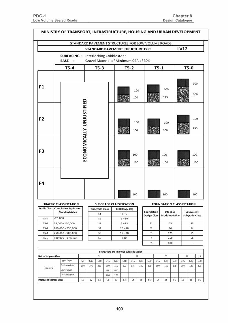
PDG-1 Low Volume Sealed Roads
Chapter 8 Design Catalogue
109
�
����(��(����)�)��������)���) ����������2� 9�����/4��6�+����������)������ �������)����������)�������+,�����:
�7�� �7�� �7�� �7�� �7��
��
��
��
��
������������������� ��2��()������������� ���(������������������
��������������������������������)�������2���(������()�)����)��
��4�/4�/��4�;);�������+���;������6�����6�);���4/�
� ����
� �
�
� ���
� ��
� � �
� � �
� � �
)��
����������
����)(
���00���6�1�� � �� �� ��� ��� �� ��� ��� �� ��� ��� �� ��� �� ���2�/4������� � ��� �� �� �� � ��� � ��� � �� ��� � ��� �65���6�1�� � ���2�/4������� � ���
�� �� �� �� �� �� �� �� �� �� �� �� �� �� ������������� !�"���#"$$
+�00��6
���%�"&'�%$�"%������������� !�"���(�$'!%
�"&'����� !�"���#"$$ ���� �� ��
�� !�"���#"$$ ����"%!��(8)
�� ��)���
���� ?��* �� ��)��
���� ��*����* �� ��)��� �� �� ��
���� �*�)���* �� ��)�� �� + ��
���� ��*�)��* �� ���)�� �� ��� ��
��� �*�)��������� �� @� �� �� ��
�� � �
��"**'+�#"$$ ���#"&'���),�'�"#�%&��&"%�"����-#�$ ���%�"&'�%�
(�$'!%�#"$$)**�+&'���
����#�$�(��")),�'�"#�%&�
�� !�"���#"$$

PDG-1 Low Volume Sealed Roads
Chapter 8 Design Catalogue
110
8.4.13 Pavement Structure Type LV13 (Interlocking Concrete Block Surfacing on G30 Base) This is a flexible pavement structure; highly economic for use especially in urban areas. In areas where gravel of base quality is scarce, but concrete block paving can easily be obtained, this is an ideal type of pavement. Moreover, in urban areas this provides an opportunity to employ local people in the production of the blocks and laying/packing the blocks on the road. If a sufficient number of masons are employed the process is rapid, but if there are an insufficient number of masons the process can be rather slow.
Materials
Surfacing Materials: Concrete block paving.
Base Materials: Lateritic gravel, quartzitic gravel, “soft stone”, calcareous gravel, coral rag, and clayey/silty sand.
Materials Specifications and Construction Procedures
Concrete block paving for surfacing: See chart PB2.
Natural gravels for base: See chart GM6.
Capping layers: - See charts GM1, GM2, GM3, GM4, and GM5.

PDG-1 Low Volume Sealed Roads
Chapter 8 Design Catalogue
111
����(��(����)�)��������)���) ����������2�� 9����������+��������,����� ��������������)������ �� ����) ��� �����)�����+,��������
�7�� �7�� �7�� �7�� �7��
��
��
��
��
��������������������������������)�������2���(������()�)����)��
��4�/4�/��4�;);�������+���;������6� ���6�);���4/�
������������������� ��2��()������������� ���(������������������
!�� !"�#��
����
��
!�� !��!"�
�� ����
!�� !�� !��
�� �� ��
�� �� ��
)��
����������
����)(
�"�$$���6 %�� �� �!� �!� �!" �!" �!� �!" �#" ��� �!" �#" ��� �#" ��� ����&���''����� ��� #(" �"� !"� !"� !�� !(" #�� ##" !�� !"� !(" !�� !#" !��6�)���6 %�� �� �!��&���''����� #�� !("
�# �# �� �� �� �� �* �" �+ �* �" �+ �" �+ �+����������� !�"���#"$$
+ $$��
���%�"&'�%$�"%������������� !�"���(�$'!%
�"&'����� !�"���#"$$ �#�! �� �*
�� !�"���#"$$ ����"%!��(8)
�! #�,�"�
�"�* -#".��� �# "�,�!�
�"�� #".������!��.��� �� (�,�!� �! +" ��
�"�# !��.����,�#"�.��� �* !��,�!� �# /� �*
�"�! #"�.����,�"��.��� �" !"�,��� �� !#" �"
�"�� "��.����,�!������ �+ 0�� �* #"� �+
�" *�� �
��"**'+�#"$$ ���#"&'���),�'�"#�%&��&"%�"����-#�$ ���%�"&'�%�
(�$'!%�#"$$)**�+&'���
����#�$�(��")),�'�"#�%&�
�� !�"���#"$$

PDG-1 Low Volume Sealed Roads
Chapter 8 Design Catalogue
112
8.4.14 Pavement Structure Type LV14 (Cement Concrete Base or Surfacing on G30 Sub-base) This is a rigid pavement structure; suitable for use on steep sections of road where construction and performance of bituminous surfacings could prove challenging. It is also useful in areas where frequent heavy vehicles turn or park – such as at market towns. The key requirements are that the concrete should be well-cured to minimise cracking, and the slabs should be connected to each other by adequate steel dowels (minimum diameter 16 mm). A well-constructed sub-base (camber, thickness, compaction, strength) is extremely important in this case.
Initial costs are high, but this is offset by the long life of the concrete pavement.
Materials
Base/Surfacing Materials: Concrete, minimum compressive strength 25 MPa.
Base Materials: Lateritic gravel, quartzitic gravel, “soft stone”, calcareous gravel, coral rag, and clayey/silty sand.
Materials Specifications and Construction Procedures
Cement Concrete Base/Surfacing: See chart CP-1.
Natural gravels for base: See chart GM6.
Capping layers: - See charts GM1, GM2, GM3, GM4, and GM5.
�

PDG-1 Low Volume Sealed Roads
Chapter 8 Design Catalogue
113
����(��(����)�)��������)���) ����������2� +��� �+� +����,�-�0�����+ /���)������ �������1���������1 ����+,��������
�7�� �7�� �7�� �7�� �7��
��
��
��
��
��������������������������������)�������2���(������()�)����)��
��42/4�/��4�;1;2����� +� �;���3��43$��34 1;��34/�
������������������� ��2��()������������� ���(������������������
!�� !#"!("
!�� !��!��
!�� !#" !"�
!�� !��!��
!�� !�� !��
!�� !�� !��
!�� !�� !��
)��
����������
����)(
�" ((���4�)�� �� �!� �!� �!" �!" �!� �!" �#" ��� �!" �#" ��� �#" ��� ����*+, �--����� ��� #(" �"� !"� !"� !�� !(" #�� ##" !�� !"� !(" !�� !#" !��4�.���4�)�� �� �!��*+, �--����� #�� !("
�# �# �� �� �� �� �* �" �+ �* �" �+ �" �+ �+����������� !�"���#"$$
+�(( /
���%�"&'�%$�"%������������� !�"���(�$'!%
�"&'����� !�"���#"$$ �#�! �� �*
�� !�"���#"$$ ����"%!��(8)
�! #�,�"�
�"�* -#"$��� �# "�,�!�
�"�� #"$������!��$��� �� (�,�!� �! +" ��
�"�# !��$����,�#"�$��� �* !��,�!� �# /� �*
�"�! #"�$����,�"��$��� �" !"�,��� �� !#" �"
�"�� "��$����,�!����� �+ 0�� �* #"� �+
�" *�� �
��"**'+�#"$$ ���#"&'���),�'�"#�%&��&"%�"����-#�$ ���%�"&'�%�
(�$'!%�#"$$)**�+&'���
����#�$�(��")),�'�"#�%&�
�� !�"���#"$$

PDG-1 Low Volume Sealed Roads
BIBLIOGRAPHY
I
����������)��
Asphalt Academy. (2009). Technical Guidance 2: Bitumen Stabilised Materials: A Guideline for the Design and Construction of Bitumen Emulsion and Foamed Bitumen Stabilised Materials. Pretoria, South Africa: Asphalt Academy.
Courteille, G., & Serfass, J. P. (n.d.). Survey of Subgrade Conditions in Kenya and their Influence on Pavement Performance. Report 345. Nairobi: Ministry of Works Materials Branch.
Gourley, C. S., & Greening, P. A. (1999). Performance of Low Volume Sealed Roads: Results and Recommendations from Studies in Southern Africa. Crowthorne, Berkshire: Transport Research Laboratory.
Highways Agency. (2009). Interim Advice Note 73/06 Revision 1: Design Guidance for Road Pavement Foundations (Draft HD25). London, UK: Highways Agency.
Ministry of Roads and Communication: Republic of Kenya. (1987). Road Design Manual Part III: Materials and Pavement Design for New Roads. Nairobi: Ministry of Roads and Communication.
Ministry of Roads and Public Works: Republic of Kenya. (1986). Standard Specifications for Road and Bridge Construction. Nairobi: Ministry of Roads and Public Works.
Ministry of Transport and Infrastructure: Republic of Kenya. (2012). Kenyan Standard KS02-827: Concrete Block Paving. Nairobi: Ministry of Transport and Infrastructure.
Ministry of Works: Republic of Kenya. (1979). Road Design Manual Part 1: Geometric Design of Rural Roads. Nairobi: Ministry of Works.
National Council for Law Reporting: Republic of Kenya. (2012). Kenya Roads Act: Chapter 408. Nairobi: National Council for Law Reporting: Republic of Kenya.
National Council for Law Reporting: Republic of Kenya. (2012). Traffic Act: Chapter 403. Nairobi: National Council for Law Reporting: Republic of Kenya.
Overby, C. (1999). Publication No. 93. A guide to the use of Otta Seals. Oslo: Directorate of Public Roads, Road Technology Department.
SABITA. (2011). Manual 28: Best practice for the design and construction of slurry seals. Cape Town: SABITA.
The South African National Roads Agency. (2007). Technical Recommendation for Highways Volume 3: Design and Construction of Surfacing Seals. Pretoria: The South African National Roads Agency.
Transport Research Laboratory. (1993). Overseas Road Note 31: A guide to the structural design of bitumen-surfaced roads in tropical and sub-tropical countries. Crowthorne: Transport Research Laboratory.
Transport Research Laboratory. (2000). Overseas Road Note 3: A guide to surface dressing in tropical and sub-tropical countries. Crowthorne: Transport Research Laboratory.
Transport Research Laboratory. (2004). Dynamic Cone Penetrometer Tests and Analysis: PR/INT/277/04. Crowthorne: TRL Limited.
Transport Research Laboratory. (2004). Overseas Road Note 40: A guide to axle load surveys and traffic counts for determining traffic loading on pavements. Crowthorne: Transport Research Laboratory.

PDG-1 Low Volume Sealed Roads
APPENDICES
�%%)*(')#�
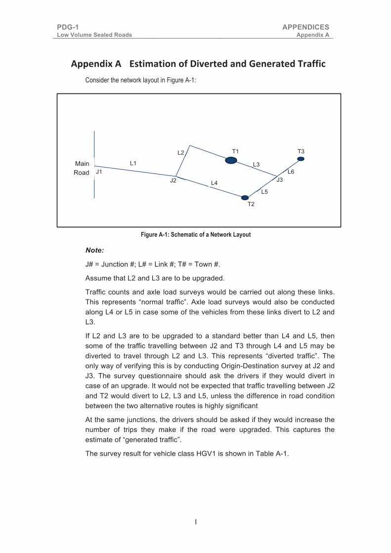
PDG-1 Low Volume Sealed Roads
APPENDICES Appendix A
I
���������� ���) �����������(������������2���������������Consider the network layout in Figure A-1:
Figure A-1: Schematic of a Network Layout
Note:
J# = Junction #; L# = Link #; T# = Town #.
Assume that L2 and L3 are to be upgraded.
Traffic counts and axle load surveys would be carried out along these links. This represents “normal traffic”. Axle load surveys would also be conducted along L4 or L5 in case some of the vehicles from these links divert to L2 and L3.
If L2 and L3 are to be upgraded to a standard better than L4 and L5, then some of the traffic travelling between J2 and T3 through L4 and L5 may be diverted to travel through L2 and L3. This represents “diverted traffic”. The only way of verifying this is by conducting Origin-Destination survey at J2 and J3. The survey questionnaire should ask the drivers if they would divert in case of an upgrade. It would not be expected that traffic travelling between J2 and T2 would divert to L2, L3 and L5, unless the difference in road condition between the two alternative routes is highly significant
At the same junctions, the drivers should be asked if they would increase the number of trips they make if the road were upgraded. This captures the estimate of “generated traffic”.
The survey result for vehicle class HGV1 is shown in Table A-1.
Main Road
T1
T2
T3
L3 L1 L2
L4 L5
L6 J3 J2
J1

PDG-1 Low Volume Sealed Roads
APPENDICES Appendix A
II
Table A-1: Recording and summation of normal and diverted traffic
Route Volume of traffic in Southbound direction
Volume of HGV1 in Northbound direction
Number on design link L2 (Southbound)
Number on design link L2 (Northbound)
Number on design link L3 (Southbound)
Number on design link L3 (Northbound)
J2-T1 7 8 7 8 0 0
J2-T1-J3-T3 6 6 6 6 6 6
J2-T2 8 9 0 0 0 0
J2-T2-J3-T3 10 10 3* 3* 3* 3*
T1-J3-T3 3 3 0 0 3* 3*
T1-J3-T2 2 2 0 0 2* 2*
T2-J3-T3 2 2 0 0 0 0
Totals 16 17 14 14
*Obtained by asking drivers during the O-D survey
The total of HGV1 in each link in each direction, including diverted traffic, would be reported and summed as in Table A-1. That is 16 on L2 southbound, 17 on L2 northbound, 14 on L3 for both southbound and northbound. If during the survey 10 drivers indicated that they would make one more return trip along L2 and L3 (generated traffic), then the sums would be 26, 27, 24 and 24. The growth rate would be applied to this figure in order to estimate the design traffic. Similar tables would be used to collate data for other vehicle classes. Axle load weights would also be recorded in a similar format and used to calculate the design traffic, as discussed in Chapter 2. The result may be slightly conservative, since it is difficult to estimate generated traffic accurately. Moreover, if in this case L4 and L5 are improved shortly after L2 and L3, then some of the diverted traffic will move back to their original routes.
�
�

PDG
-1
Low
Vol
ume
Seal
ed R
oads
APP
END
ICES
A
ppen
dix
A
III
��
Figu
re A
-2: T
raffi
c Ta
llyin
g Fo
rm

PDG-1 Low Volume Sealed Roads
APPENDICES Appendix B
IV
���������� ��������������� ����������� ������������If the DESA and the traffic growth rate ‘r’ are known, then the CESA can be read from Table B-1. Table B-1 is based on a design period of 15 years.
Note that if the growth rate for each vehicle class is different, then the CESA is the sum of the individual CESAs obtained from the combination of the DESA and the corresponding growth rate for each vehicle class.
Table B-1: Lookup Table for CESA
Average daily ESA at beginning of the design life
CESA at specified growth rate (growth rate in %)
2 3 4 5 6 7 8 9 10 12 15
2 0.01 0.01 0.01 0.02 0.02 0.02 0.02 0.02 0.02 0.03 0.03
3 0.02 0.02 0.02 0.02 0.03 0.03 0.03 0.03 0.03 0.04 0.05
4 0.03 0.03 0.03 0.03 0.03 0.04 0.04 0.04 0.05 0.05 0.07
5 0.03 0.03 0.04 0.04 0.04 0.05 0.05 0.05 0.06 0.07 0.09
10 0.06 0.07 0.07 0.08 0.08 0.09 0.10 0.11 0.12 0.14 0.17
15 0.09 0.10 0.11 0.12 0.13 0.14 0.15 0.16 0.17 0.20 0.26
20 0.13 0.14 0.15 0.16 0.17 0.18 0.20 0.21 0.23 0.27 0.35
25 0.16 0.17 0.18 0.20 0.21 0.23 0.25 0.27 0.29 0.34 0.43
30 0.19 0.20 0.22 0.24 0.25 0.28 0.30 0.32 0.35 0.41 0.52
35 0.22 0.24 0.26 0.28 0.30 0.32 0.35 0.38 0.41 0.48 0.61
40 0.25 0.27 0.29 0.32 0.34 0.37 0.40 0.43 0.46 0.54 0.69
45 0.28 0.31 0.33 0.35 0.38 0.41 0.45 0.48 0.52 0.61 0.78
50 0.32 0.34 0.37 0.39 0.42 0.46 0.50 0.54 0.58 0.68 0.87
60 0.38 0.41 0.44 0.47 0.51 0.55 0.59 0.64 0.70 0.82 1.04
70 0.44 0.48 0.51 0.55 0.59 0.64 0.69 0.75 0.81 0.95 1.22
80 0.50 0.54 0.58 0.63 0.68 0.73 0.79 0.86 0.93 1.09 1.39
90 0.57 0.61 0.66 0.71 0.76 0.83 0.89 0.96 1.04 1.22 1.56
100 0.63 0.68 0.73 0.79 0.85 0.92 0.99 1.07 1.16 1.36 1.74
110 0.69 0.75 0.80 0.87 0.93 1.01 1.09 1.18 1.28 1.50 1.91
120 0.76 0.81 0.88 0.95 1.02 1.10 1.19 1.29 1.39 1.63 2.08
130 0.82 0.88 0.95 1.02 1.10 1.19 1.29 1.39 1.51 1.77 2.26
140 0.88 0.95 1.02 1.10 1.19 1.28 1.39 1.50 1.62 1.90 2.43
150 0.95 1.02 1.10 1.18 1.27 1.38 1.49 1.61 1.74 2.04 2.61
160 1.01 1.09 1.17 1.26 1.36 1.47 1.59 1.71 1.86 2.18 2.78

PDG
-1
Low
Vol
ume
Seal
ed R
oads
APP
END
ICES
A
ppen
dix
C
V
����
������
������ ���
����������
�����
����
Tabl
e C-1
: Alig
nmen
t Soi
l Tes
t Res
ults
For
m
CHAI
NAGE
TP
NO
.
Sam
ple
Desc
riptio
n Ge
o-Re
fere
nce
(UTM
– Ar
c 196
0)
% P
assin
g Si
eve S
ize (m
m)
LL
PL
PI
LS
PM
MDD
OMC
CBR
Swell
Ma
teria
l Cl
assif
icatio
n
East
ing
North
ing
50
37.5
20
10
5 2
1.18
0.6
0.425
0.2
12
0.15
0.075
0.0
63
Soil Group
Bearing Strength Class
Not
es:
(i).
This
form
sho
uld
be p
rese
nted
in A
3 pa
per s
ize
and
incl
uded
in th
e m
ater
ials
repo
rt.
(ii).
Mat
eria
l ty
pe d
escr
iptio
n sh
all
be i
n ac
cord
ance
with
the
par
ticle
dis
tribu
tion
char
t (F
orm
2N
) of
BS
137
7-2:
1990
and
The
Brit
ish
Soi
l C
lass
ifica
tion
Sys
tem
for E
ngin
eerin
g P
urpo
ses
(BS
CS
) as
per T
RR
L La
bora
tory
Rep
ort 1
030,
198
1. T
he B
SC
S is
sum
mar
ised
in T
able
C-3
, Fi
gure
C-1
and
tria
ngul
ar d
iagr
ams
of F
igur
es C
-2,
C-3
, an
d C
-4.
Par
ticle
siz
e ra
nges
and
nom
encl
atur
e of
soi
l gro
ups
are
sum
mar
ised
be
low
.
(iii).
Sub
grad
e be
arin
g st
reng
th c
lass
ifica
tion
shal
l be
in a
ccor
danc
e w
ith T
able
6.1
.1 o
f Roa
d D
esig
n M
anua
l Par
t III

PDG
-1
Low
Vol
ume
Seal
ed R
oads
APP
END
ICES
A
ppen
dix
C
V
I
Tabl
e C-2
: Par
ticle
Size
Ran
ges a
nd N
omen
clatu
re o
f Soi
l Gro
ups
Soil
Part
icle
Gro
up
Soil
Type
Pa
rtic
le
Size
/Dia
met
er (m
m)
Sym
bol
Qua
lifyi
ng T
erm
s
Ver
y C
oars
e P
artic
les
Bou
lder
s O
ver 2
00
B
Cob
bles
20
0 –
60
Cb
Coa
rse
Par
ticle
s G
rave
l 60
– 2
G
W
ell
grad
ed
(W),
and
Poo
rly
grad
ed
(P)
whi
ch
may
be
di
ffere
ntia
ted
into
uni
form
(Pu)
or G
ap g
rade
d (P
g)
S
and
2 –
0.06
S
Fi
ne P
artic
les
Silt
0.
06 –
0.0
02
M
In t
erm
s of
pla
stic
ity:
Low
(L
), in
term
edia
te (
I), H
igh
(H),
Ver
y hi
gh (
V)
and
Upp
er p
last
ic r
ange
(U
) in
corp
orat
ing
grou
ps I,
H, V
&
E.
C
lay
Und
er 0
.002
C
Org
anic
Com
pone
nts
Pea
t
Pt
Org
anic
(O)

PDG-1 Low Volume Sealed Roads
APPENDICES Appendix C
VII
Table C-3: Soil Groups according to British Soil Classification System for Engineering Purposes
Source: TRRL Laboratory Report 1030, 1981, British Soil Classification System for Engineering Purposes

PDG-1 Low Volume Sealed Roads
APPENDICES Appendix C
VIII
Figure C-1: Plasticity Chart for the Classification of Fine Soils and the Finer Part of Coarse Soils (<425µm)
Source: TRRL Laboratory Report 1030, 1981, British Soil Classification System for Engineering Purposes

PDG-1 Low Volume Sealed Roads
APPENDICES Appendix C
IX
Figure C-2: Fuller Description of Gravels and Sands
Source: TRRL Laboratory Report 1030, 1981, British Soil Classification System for Engineering Purposes

PDG-1 Low Volume Sealed Roads
APPENDICES Appendix C
X
Figure C-3: The grading Triangle for Soil Classification (material finer than 60mm)
Source: TRRL Laboratory Report 1030, 1981, British Soil Classification System for Engineering Purposes

PDG-1 Low Volume Sealed Roads
APPENDICES Appendix C
XI
Figure C-4: Mixtures of Very Coarse Materials (Boulders and Cobbles) and Finer Material
Source: TRRL Laboratory Report 1030, 1981, British Soil Classification System for Engineering Purposes

PDG-1 Low Volume Sealed Roads
APPENDICES Appendix D
XII
���������( ����������� ������������������������������������(�������
Subgrade strains for LV1, LV2 and LV3 in the design catalogue were computed based on the median CBR subgrade values to check compliance with the Kenya Fatigue Law and comparison with Shell 85, Shell 50, USA Medium, CSIR and US Heavy subgrade failure criterions.
The subgrade strains were computed using the multi-layer layer linear elastic model BISAR developed by Shell, but there are several similar MLE models available that should give the same results. The elastic moduli used in the analysis are presented and discussed in Chapter 6 of this guideline.
The design parameters adopted for the MLE analysis were as follows:
• Layer thicknesses
• Dual wheel load of standard axle (80 kN)
• Tyre contact pressure of 577 kPa
• Tyre contact radius 10.5 cm
• Centre to centre spacing between dual wheels 31.5 cm
• Stress/Strain analysis co-ordinates (3-axes)
• Material moduli as shown in Table 6-3, Table 6-4, and Table 6-5
• Poisson’s ratio (0.35 for all materials)
• Friction between the layers (full contact)”
�Figure D-1: Strains, S1
�

PDG-1 Low Volume Sealed Roads
APPENDICES Appendix D
XIII
�
�
Figure D-1: Strains, S2
Figure D-1: Strains, S3
�
�

PDG-1 Low Volume Sealed Roads
APPENDICES Appendix D
XIV
�
�
Figure D-1: Strains, S4
Figure D-1: Strains, S5�

PDG-1 Low Volume Sealed Roads
APPENDICES Appendix E
XV
���������) ������������ ��������������(������������������������
)�� ����������
The Structural Number (SN) method is a very useful method of determining the overall strength, and therefore the traffic carrying capacity, of road pavements. It was developed during the analysis of the performance of the many test sections built for the AASHO Road Test, carried out in the USA between 1959 and 1961. This is the largest controlled road pavement experiment ever carried out and it is unlikely to ever be repeated. Many concepts were developed from the data and many have been adopted throughout the world, but, like all empirically based systems, it should only be used within the range of the engineering parameters from which it was developed. It is an invaluable tool for developing pavement structural designs.
)�� �����!������
The structural number is a measure of the total thickness of the road pavement weighted according to the ‘strength’ of each layer and calculated as follows:
SN = 0.0394 ∑ai.hi
where:
SN = structural number of the pavement,
ai = strength coefficient of the ith layer,
hi = thickness of the ith layer, in millimetres,
and the summation is over the number of pavement layers, n.
The individual layer strength coefficients are determined from the normal tests that are used to define the strength of the material in question e.g. CBR for granular materials, UCS for cemented materials, etc. Different authorities developed their own correlations between normal strength measures and the derived strength coefficients, hence several slightly different scales are in use. However, the differences are small and unimportant considering the nature of the materials in question and the precision that can be achieved in pavement design. Table E-1 shows the values used in this study.
The coefficients can be modified to take into account the deterioration or weakening of the materials caused by environmental effects, for example, high moisture contents in unbound materials caused by poor drainage and high temperature conditions affecting bituminous materials.
�
�
�

PDG-1 Low Volume Sealed Roads
APPENDICES Appendix E
XVI
Table E-1: Pavement Layer Strength Coefficients
Layer
Layer Type Condition Coefficient
Surfacing
Surface dressing ai = 0.2
New asphalt concrete 1,2
wearing
MR30 = 1500 MPa ai = 0.30
MR30 = 2000 MPa ai = 0.35
MR30 = 2500 MPa ai = 0.40
MR30 ≥ 3000 MPa ai = 0.45
Road base
Asphalt concrete As above As above
Granular unbound
Default ai = (29.14 CBR - 0.1977 CBR2 + 0.00045 CBR3) 10-4
G100 (CBR > 100%) 0.14
G80 (CBR = 80%)
With a stabilised layer underneath 0.138
With an unbound granular layer underneath 0.133
G65 (CBR = 65%) (4) 0.125
G65 (CBR = 60%) (4) 0.123
G50 (CBR = 50%)(4) 0.118
G30 (CBR = 30%)(4) 0.105
G25 (CBR = 25%)(4) 0.101
Bitumen treated gravels and sands
Marshall stability = 2.5 MN a = 0.135
Marshall stability = 5.0 MN a = 0.185
Marshall stability = 7.5 MN a = 0.23
Cemented3
Equation ai = 0.075 + 0.039 UCS – 0.00088(UCS)2
CB 1 (UCS = 3.0 – 6.0 MPa) a = 0.18
CB 2 (UCS = 1.5 – 3.0 MPa) a = 0.13
Sub-base and capping
Granular unbound
Equation aj = 0.01 + 0.065*log10 CBR
G30 (CBR = 30%) a = 0.106
G25 (CBR = 25%) a = 0.101
G20 (CBR = 20%) a = 0.095
G15 (CBR = 15) a = 0.086
G10 (CBR = 10) a = 0.075
G8 (CBR = 8) a = 0.069
Cemented (UCS = 0.7 – 1.5 MPa) a = 0.1

PDG-1 Low Volume Sealed Roads
APPENDICES Appendix E
XVII
�Notes:
Unconfined Compressive Strength (UCS) is quoted in MPa at 14 days.
MR30 is the resilient modulus by the indirect tensile test at 30 °C.
Used for low volume roads.
)�� !������������������ ���
The AASHO Road Test was constructed on a single subgrade, therefore the effect of different subgrades could not be estimated and the structural number could not include a subgrade contribution. To overcome this problem and to extend the concept to all subgrades, a subgrade contribution was derived as described by Hodges et al. (1975) and a modified structural number defined as follows:
SNC = SN + 3.51 (log10 CBRs) – 0.85 (log10 CBRs)2 – 1.43
where:
SNC = Modified structural number of the pavement
CBR = in-situ CBR of the subgrade
The modified structural number (SNC) has been used extensively and forms the basis for defining pavement strength in many pavement performance models.
)"� ��#��������������� ���
When evaluating a pavement in order to design rehabilitation measures, it is found that many pavements cannot be divided easily into distinct roadbase and sub-base layers with a well-defined and uniform subgrade. Hence, when calculating the structural number according to the equation above, the engineer has to judge which layers to define as roadbase, which as sub-base, and where to define the top of the subgrade. For many roads this has proven quite difficult. There are often several layers that could be considered either as sub-bases or part of the subgrade, especially where capping layers or selected fill have been used. The simple summation over all the apparent layers allows the engineer to obtain almost any value of structural number, since the value will depend on where the engineer assumes that the sub-base(s) end and the subgrade begins. In the past this problem has been addressed by simply limiting the total depth of all the layers that are considered to be road pavement. However, this is somewhat arbitrary, has not been used universally and has led to unacceptably large errors in some circumstances.
The problem arises because the contributions of each layer to the structural number are independent of depth. This cannot be correct since logic dictates that a layer that lies very deep within the subgrade can have little or no influence on the performance of the road. To eliminate the problem, a method

PDG-1 Low Volume Sealed Roads
APPENDICES Appendix E
XVIII
of calculating the modified structural number has been devised in which the contributions of each layer to the overall structural number decrease with depth (Rolt and Parkman, 2000).
To distinguish the structural number derived from the original Modified Structural Number (SNC), the new structural number is called the Adjusted Structural Number (SNP). It is calculated as follows:
SNP = SNA + SNS + SNG
Where the component terms are calculated follows;
SNA = 0.0394 ai hi
SNS = 0.0394
-
�
SNG = (b0 - b1exp(-b2zm)) (exp(-b3zm)) [3.51 log10CBRs - 0.85(log10CBRs)
2 - 1.43]
� �
and
SNP = adjusted structural number of the pavement
SNA = contribution of surfacing and base layers
SNS = contribution of the sub-base and selected fill layers
SNG = contribution of the subgrade
n = number of base and surfacing layers (i = 1, n)
ai = layer coefficient for base or surfacing layer i
hi = thickness of base or surfacing layer i, in mm
m = number of sub-base and selected fill layers (j = 1, m)
aj = layer coefficient for sub-base or selected fill layer j for season s
z = depth parameter measured from the top of the sub-base (underside of base), in mm
zj = depth to the underside of the jth layer (z0 = 0), in mm
CBR = in situ subgrade CBR
The values of the model coefficients b0 to b3 are given in Table H.5.
∑=
n
1i
∑=
m
1jja⎪⎩
⎪⎨⎧
⎟⎟⎠
⎞⎜⎜⎝
⎛
+
+−+
−
−
)b(b))zb(b(expb
b)zb(expb
32
j321
3
j30
⎪⎭
⎪⎬⎫⎟⎟⎠
⎞⎜⎜⎝
⎛
+
+−+
−
− −−
)b(b))zb(b(expb
b)zb(expb
32
1j321
3
1j30

PDG-1 Low Volume Sealed Roads
APPENDICES Appendix E
XIX
Table E-2: Adjusted Structural Number Model Coefficients
b0 b1 b2 b3
1.6 0.6 0.008 0.00207 �
It should be noted that for roads that have been built according to the designs in the Pavement Design Manual with well-defined layers of uniform strength, the Adjusted Structural Number and the Modified Structural Number are essentially identical. The value of SNP is calculated when evaluating a pavement with many layers of varying strength.
E5 SN vs Traffic
The result of the analysis of successful LVRs constructed in Kenya and successful designs based on the long-term performance study conducted by C Gourley and P A K Greening in Zimbabwe, Botswana and Malawi is a catalogue of structures with SN values conforming to Figures E1 and E2 for road classes LV1, LV2 and LV3.
Figure E-1: Structural Number versus Traffic, for Various Subgrade Strengths
�
�
�

PDG-1 Low Volume Sealed Roads
APPENDICES Appendix E
XX
�
�
�
Figure E-2: Structural Number versus Subgrade CBR, for Various Traffic Levels
�